1
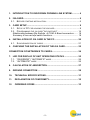
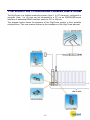
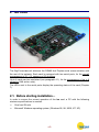
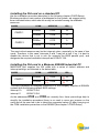
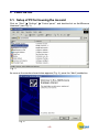
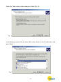
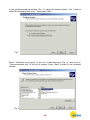
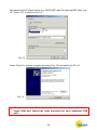
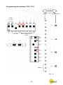
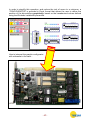
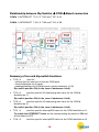
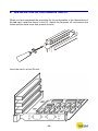
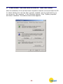
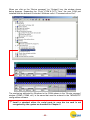
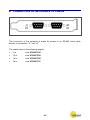
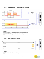
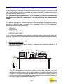
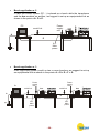
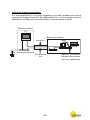
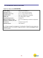
INSTRUCTION MANUAL
1. INTRODUCTION TO DIGICROWN PROBING LINE SYSTEM ............ 4
2. ISA CARD .............................................................................................. 6
2.1.
BEFORE STARTING INSTALLATION… .................................................... 6
3. CARD SETUP ........................................................................................ 8
3.1. SETUP OF PC FOR HOUSING THE ISA CARD .......................................... 8
3.2. PROGRAMMING THE ISA CARD “DIP-SWITCHES” .................................. 14
Relationship between Dip Switchs Æ COM Æ Board connectors ....... 18
Summary of isa card dip-switch functions............................................ 18
4. INSTALLATION OF ISA CARD IN THE PC........................................ 20
4.1.
SYNCHRONIZATION OF CARDS ........................................................... 21
5. CHECKING THE INSTALLATION OF THE ISA CARD...................... 22
CONNECTION OF NETWORKS TO CARDS............................................ 24
7. LED FOR DISPLAY OF UNIT OPERATING STATUS ....................... 25
7.1.
7.2.
“ON ERROR” / “AUTOMATIC” MODE ............................................. 26
“AUTOMATIC” MODE ...................................................................... 26
8. CALCULATION OF ABSORPTION .................................................... 27
9. GROUND CONNECTION .................................................................... 28
10.
TECHNICAL SPECIFICATIONS ...................................................... 31
11.
DECLARATION OF CONFORMITY................................................. 32
12.
ORDERING CODES......................................................................... 33
-2-
-3-
1. INTRODUCTION TO DIGICROWN PROBING LINE SYSTEM
The DigiCrown is a flexible measuring system (from 1 to 372 sensors), configured in
networks (from 1 to 12) that can be connected to a PC via an RS232/USB serial
interface or dedicated RS485 interface cards for PCI or ISA bus.
The diagram below shows the elements of the DigiCrown system in their possible
configurations. This user manual follows up the installation of the DigiCrown isa card.
-4-
/USB
NET 1
NET 1
NET 2
MAX 6 CARDS
-5-
2. ISA CARD
The DigiCrown isa unit achieves the RS485 Half Duplex serial communication with
the rest of the network. Each card is equipped with two serial ports, for the overall
management of 31 + 31 sensors or I/O modules.
Up to 4 cards can be interlinked (see paragraph 4.1), for the management of up to 8
networks (248 active units).
The LEDs next to the serial ports display the operating status of the card (Chapter
7).
2.1. Before starting installation…
In order to ensure the correct operation of the isa card, a PC with the following
minimum specifications is needed:
•
One free ISA slot
•
Microsoft Windows operating system (Windows 95, 98, 2000, NT, XP)
-6-
Installing the ISA card on a standard PC.
Use the installation procedure described in the following chapter (CARD Setup).
Windows provides a vast number of addresses for the system, we suggest using
those indicated below, which should usually be included among the available
resources.
CARDS
CARD 1
CARD 2
COM#
ADDRESS
IRQ
COM a
0100
10
COM b
0108
11
COM c
0110
5
COM d
0118
7
The most critical resource may be the interrupt value, especially in the case of two
cards. Therefore, in this case, interrupts 5 and 7 may be at risk. If so, it is best to
disable the device that is not in use (for example the BIOS parallel port), and
designate the required available interrupts as LEGACY ISA.
Installing the ISA card in a Marposs E9066N industrial PC
MARPOSS SpA supplies the ISA cards with a series of default address and
interrupt settings, as indicated in the below table:
CARDS
CARD 1
COM#
COM a
ADDRESS
(*) 0100
IRQ
(*) 10
COM b
(*) 11
(*) 0108
To simply installation on Marposs Industrial PCs, the company supplies all E9066N
systems with the following default BIOS settings:
interrupt 10
LEGACY ISA
interrupt 11
LEGACY ISA
As the addresses 0100 and 0108 are normally free, these pre-settings help to
simplify the installation procedure (there is no need to move any jumpers on the
card) and all the user has to do is select the suggested values (*) when carrying out
the COM installation procedure on the E9066N (see chapter 3 CARD Setup)
-7-
3. CARD SETUP
3.1. Setup of PC for housing the isa card
Click on “Start” Æ “Settings” Æ “Control panel” and double-click on Add/Remove
Hardware” (see Fig. 3).
Fig. 3
As soon as the window shown below appears (Fig. 4), press the “Next” pushbutton.
Fig. 4
-8-
Select the “Add a device” option and press “Next” (Fig. 5).
Fig. 5
In the following window (Fig. 6), select “Add a new device” in the list of devices, and
press “Next”.
Fig. 6
-9-
In the guided-procedure window (Fig. 7), select the second option, “No, I want to
select the hardware from a list” , then press “Next”.
Fig. 7
Select “(Standard port types)” in the list of manufacturers (Fig. 8), and click on
“Communications port” in the list of models. Press “Next” to pass to the following
window.
Fig. 8
- 10 -
In the window shown below (Fig. 9), select the option “Ports (COM & LPT)” , then
press “Next”.
Fig. 9
Should the warning message shown below appear, click on “OK”.
- 11 -
Set a basic configuration value that does not produce any conflict in the system
(Fig. 10), making sure that the “No conflicts” message appears in the “Conflicting
device list” box (e.g. “Basic configuration 0005”). Then double-click on
“IRQ/Interrupt Request”.
Fig. 10
Enter the interrupt-level value that you wish to set for the isa card (e.g. Value 03),
making sure that there is no conflict (Fig. 11). Press “OK” to confirm.
Fig. 11
- 12 -
Write down the I/O interval value (e.g. 02E8-02EF) and the interrupt/IRQ value (e.g.
03). Press “OK” to confirm (Fig. 12).
Fig. 12
Press “Finish” in order to complete the setup (Fig. 13) and switch the PC off.
Fig. 13
) The operations described in para. 3.1 refer to the setup procedure for a
single COM port. Repeat the same procedure for each additional COM
port.
- 13 -
3.2.
Programming the isa card “dip-switches”
Once the card addressing procedure has been completed, it is necessary to define
the following values by programming the dip-switches:
1.
The I/O interval start value (e.g.: 0100).
IMPORTANT: position ON = Ø (see example in fig. 14).
In this case, the following dip-switches are used:
T102 and T103 Æ COM a Æ which communicates via connector J1
T102 and T106 Æ COM b Æ which communicates via connector J2
2.
The interrupt value.
IMPORTANT: to select the interrupt, set only the corresponding dip-switches to
ON. All the other dip-switches must be set to OFF (see example in fig. 14).
In this case, the following dip-switches are used:
T101 Æ INTERRUPT CHA Æ COM a (which communicates via connector J1)
T104 Æ INTERRUPT CHB Æ COM b (which communicates via connector J2)
When setting the dip-switches it is important to bear in mind that each hexadecimal
digit must be converted into 4 binary digits for use in the programming procedure
illustrated in the diagram (fig. 14).
- 14 -
Programming dip-switches T102 / T103
I/O INTERVAL
binary
hexadecimal
COM
on / off
Not used
Basic address for all
cards
default
Fig. 14
- 15 -
Programming dip-switches T102 / T106
I/O INTERVAL
binary
hexadecimal
COM
on / off
Not used
Basic address for all
cards
default
Fig. 14
- 16 -
In order to simplify this operation, and reduce the risk of errors to a minimum, a
“CONFIGURATOR” is provided in Excel format that allows the user to define the
position of the dip-switches graphically, based on the hexadecimal values defined
using the Windows installation procedure.
How to interpret the graphic configurator
with reference to the card…
- 17 -
Relationship between Dip Switchs Æ COM Æ Board connectors
COM a Æ INTERRUPT T101 Æ T103 and T102 Æ J1
COM b Æ INTERRUPT T104 Æ T106 and T102 Æ J2
Summary of isa card dip-switch functions
•
T102 Æ
used for:
- settings that are common to the two COM ports
– basic addresses for all cards
- enabling/disabling the COM a/b ports (serial connectors J1/J2)
Dip-switch position ON (in the case of addresses: bit=0)
•
T103 Æ
sets the specific I/O addressing start value for the COM a
identified as J1.
Dip-switch position ON (in the case of addresses: bit=0)
•
T106 Æ
sets the specific I/O addressing start value for the COM a
identified as J2.
Dip-switch position ON (in the case of addresses: bit=0)
•
T101 Æ
sets the specific interrupt/IRQ value for the COM identified as J1.
To enable the INTERRUPT value set the corresponding dip-switch to ON and
all the others to OFF.
•
T104 Æ
sets the specific interrupt/IRQ value for the COM identified as J2.
- 18 -
To enable the INTERRUPT value set the corresponding dip-switch to ON and
all the others to OFF.
N.B.:
• T101 + T104 must not have the same interrupt enabled.
• If a COM (a or b) is disabled (by setting the corresponding position on
T102), set all the corresponding INTERRUPT dip-switches to OFF in
order to free this resource on the BUS and make it available to other
devices.
Example:
COM a disabled
T102 Æ dip switch CHA set to OFF
T101Æ all dip-switches set to OFF
or
COM b disabled
T102 Æ dip switch CHB set to OFF
T104Æ all dip-switches set to OFF
- 19 -
4. INSTALLATION OF ISA CARD IN THE PC
When you have completed the procedure for the configuration of the dip-switches of
the isa card, install the device in the PC. Switch the computer off, and remove the
frame and the metal cover that protects the slot.
Insert the card in a free ISA slot.
- 20 -
4.1. Synchronization of cards
The cards are interlinked by means of the OUT-IN connectors (Fig. 14), using the
10-pins flat cable that is supplied (Fig. 15). This connection extends the
synchronization of the measurement reference frequencies between the various
networks to up to 4 isa cards (=8 networks). An “isofrequency” system is thus
obtained.
The flat cable must be connected to the OUT connector of a card, which becomes
the master one, and to the IN connector of the next card. If further cards are
present, the OUT connector is connected to the IN connector of the third one, and
so on.
OUTPUT
Connector
INPUT
Connector
Fig. 14
Fig. 15
- 21 -
5. CHECKING THE INSTALLATION OF THE ISA CARD
After the installation of the card has been completed, close the cover and restart the PC.
To check whether the card has been correctly installed, click the right-hand key of
the mouse on “My computer”, in the Windows desktop. Click “System properties”
and select “Hardware”: the window shown below appears.
- 22 -
When you click on the “Device manager” (or “System”) key, the window shown
below appears. Expanding the “Ports (COM & LPT)” item, the new COM port
installed with the isa card is included: Windows calls it “Communications Port”.
The numbering attributed by Windows to the COMs shown in the “Device manager”
window (COM5, COM6, etc.) is the same that must be entered in the “MDHQSPC”
configuration software.
) Install a standard driver for serial ports in case
recognized by the system as described in Chapter 5.
- 23 -
the isa card is not
6. CONNECTION OF NETWORKS TO CARDS
The connection of the networks is made by means of an RS-485 serial cable,
directly to connectors “J1” and “J2”.
The cables come in the following lengths:
•
2m
code 6738057016
•
10 m
code 6738057023
•
15 m
code 6738057022
•
25 m
code 6738057017
- 24 -
7. LED FOR DISPLAY OF UNIT OPERATING STATUS
The type of lighting of the red LED on the isa module indicates the operating status
of the unit. There are the following flashing modes:
•
•
“ON ERROR” (the LED is activated only when an error is generated)
“AUTOMATIC" (this mode includes both the ON ERROR warning and brief
flashes to indicate the network sessions pending).
- 25 -
7.1. “ON ERROR” / “AUTOMATIC” mode
Notes:
(1) HW ERROR Æ general hardware and bootstrap errors
(2) COM ERROR Æ general serial driver and/or protocol error
7.2. “AUTOMATIC” mode
Note:
(3) OK Æ the network is in working order
- 26 -
8. CALCULATION OF ABSORPTION
To calculate the total absorption of the card and networks from the +5 V of the ISA
slot, consider:
Vnetwork = 7.5 Vdc
Pcard = 1.5 W
K = 1.25 (efficiency of DC/DC converter)
Inetwork = Imodules x Nmodules
Pnetwork = Vnetwork x Inetwork
Ptotal absorbed = Pnetwork x K + Pcard
E.g.: the example shown below is specific for a DigiCrown configuration with a
maximum RS-485 cable length of 10 m.
Nmodules = 31 + 31 = 62
Imodules = 0.04 A
Inetwork = 62 x 0.04 = 2.48 A
Pnetwork = 7.5 x 2.48 = 18.6 W
Ptotal absorbed = 18.6 x 1. 25 + 1.5 = 24.75 W
- 27 -
9. GROUND CONNECTION
In this chapter are reported different technical solutions in order to make sure the
DigiCrown system is properly grounded, according to the NET’s configuration and to
the lay-out of the different units.
The purpose of ground connection is to minimize as much as possible the
electrical noise and the interference, typically affecting the measurement
signal.
The ground connections schemes reported in this paragraph represent the optimal
solution in order to have a system fully compatible with the EMC standards,
according to the following directives:
-
73/23/EEC
2004/108/CE
EN55022: 1998 (EMC)
EN55024: 1998 (EMC)
If for a specific application the customer considers such technical solutions not
required, Marposs is not responsible for any possible inaccurate working condition
of the devices.
•
Bench application n. 1
The whole DigiCrown system (control + measurement) has been placed on a
single bench gauge.
PC
serial link
box
D
A
p.e.
The “D” equipotential connection between the box modules and the
transducers support frame, can be done whether a metallic conductive frame
is used. In the glass gauging applications the transducers support frame is
usually not a conductive material and the transducers are typically insulated, in
this case no ground connection is required.
- 28 -
•
Bench application n. 2
In case the control system (PC…) is placed on a bench while the transducers
and the box modules on another, we suggest to set-up an equipotential link as
shown in the points: A + D + E.
Power
supply
unit
PC
serial link
D
A
E
A.C.
Main
power
p.e.
•
Bench application n. 3
If the DigiCrown system is split on two or more benches, we suggest to set-up
an equipotential link as shown in the points: A + D + E + F + G.
Power
supply
unit
Power
supply
unit
Pc
serial link
box
serial link
G
F
A
E
D
p.e.
box
A.C.
Main
power
A.C.
Main
power
- 29 -
•
Automatic machine application
For such applications it is strongly suggested to provide the box units and the
transducers support frame with an equipotential link: in the automatic machine
applications the eddy-currents normally flow in the transducer’s shield.
Electrical cabinet
Pc
Measuring machine
box
serial link
pe
Ground bar
Ground bar
Equipotential
link
- 30 -
Metallic connection
between the modules
and the transducers
10. TECHNICAL SPECIFICATIONS
DigiCrown isa (code 6355322000)
Power supply ……………………....from ISA bus standard 5 V
Absorption (P) (*).....…….……...….1.5 W + power towards networks
Absorption from +5 (I).....…….……0.2 A + current towards networks
INPUT/OUTPUT……………………..DigiCrown HW&protocol compatible
RS485 rate........……………...………prog. Baud 9600 or 208333
Operating temperature...…………..standard PC
Maximum network length…………up to 1 Km (depending on network configuration)
Number of networks per card……..2
Dimensions…………………..………standard compact ISA
Absorbed power ...……..……..…….see Chapter 8
(*) Æ Power required for management of configuration. Should the power supply unit
integrated in the PC not be able to supply this power, a DigiCrown psu+psc module
must be installed.
- 31 -
11. DECLARATION OF CONFORMITY
MARPOSS S.p.A. hereby declares that the devices described in this manual comply
to the EMC electromagnetic compatibility requirements, in compliance with the
following directives:
73/23/EEC
of 02-19-1973
(LOW VOLTAGE directive)
2004/108/CE
of 01-20-2005
(EMC directive)
The devices have been designed, assembled and tested in compliance with the
following European standards:
EN55022 : 1998
(EMC)
EN55024 : 1998
(EMC)
- 32 -
12. ORDERING CODES
The tables below are a general summary of the ordering codes for all the
components of the DigiCrown Probing Line.
The highlighted parts are the elements described in this manual.
INTERFACES
ORDER CODE
ACCESSORIES
DESCRIPTION
ORDER CODE
6355200000
DESCRIPTION
767X000000
DIGI CROWN BOX
END LINE CONNECTOR
767X000200
DIGI CROWN BOX + RAM
6872030010
DIGI CROWN BUS
767Y000000
DIGI CROWN 232
6872030011
DIGI CROWN PSC
767Y010000
DIGI CROWN USB
4147000013
EU PLUG
767W000000
DIGI CROWN PSU (110-240Vac / 7,5Vdc)
4147000014
USA PLUG
767W010000
UK PLUG
DIGI CROWN PSU (24Vdc / 7,5Vdc)
4147000015
767I000000
DIGI CROWN I/O SINK
4147000016
EU CABLE
767I010000
DIGI CROWN I/O SOURCE
4147000017
USA CABLE
767I020000
DIGI CROWN I/O ONLY INPUT
6355321000
DIGI CROWN PCI
6355322000
DIGI CROWN ISA
EXTENSIONS
ORDER CODE
SW packages
DESCRIPTION
ORDER CODE
DESCRIPTION
6738057016
CONNECTION CABLE 2m
CM2Z22MA00
QSPC
6738057023
CONNECTION CABLE 10m
CM2F22MA02
EASY ACQUISITION
6738057022
CONNECTION CABLE 15m
CM2A12MA01
MARPOSS DRIVER LIBRARY
6738057017
CONNECTION CABLE 25m
- 33 -
Notes
___________________________________________
___________________________________________
___________________________________________
___________________________________________
___________________________________________
___________________________________________
___________________________________________
___________________________________________
___________________________________________
___________________________________________
___________________________________________
___________________________________________
___________________________________________
___________________________________________
___________________________________________
___________________________________________
___________________________________________
___________________________________________
___________________________________________
___________________________________________
___________________________________________
- 34 -
Notes
___________________________________________
___________________________________________
___________________________________________
___________________________________________
___________________________________________
___________________________________________
___________________________________________
___________________________________________
___________________________________________
___________________________________________
___________________________________________
___________________________________________
___________________________________________
___________________________________________
___________________________________________
___________________________________________
___________________________________________
___________________________________________
___________________________________________
___________________________________________
___________________________________________
___________________________________________
- 35 -
2002/95/CE
2002/96/CE
The product and any part that can be mechanically separated from it must not be disposed of the environment
and must not be disposed of as municipal or general waste (Law for national adoption of European directives
2002/95/EC and 2002/96/EC and others). The provisions of the law only apply to products identified as WEEE
(waste electrical and electronic equipment) marked with the appropriate symbol and in any case put on the
market after 13 August 2005. Once put out of use, the WEEE product may contain substances and parts that
are harmful to human health and the environment and which must be subject to professional treatment for
reuse, recycling or definitive disposal. Deliver the WEEE product to an authorised WEEE treatment centre, or
contact the local organisation responsible or your nearest Marposs service centre for information. Illegal
disposal of a WEEE product is a crime punishable by penalties.
A complete and updated list of the addresses is available in the Marposs website: www.marposs.com - www.testar.com
D4340034GF - Edition 09/2007 – Specifications subject to changes.
© Copyright 2006 MARPOSS S.p.A. (Italy) – All rights reserved.
MARPOSS, and other names/marks relevant to Marposs products mentioned or shown in this document, are registered trademarks
or Marposs trademarks in the United States and in other countries. Any rights of third parties to trademarks or registered trademarks
mentioned in this document are acknowledged to the respective holders.
Marposs has an integrated Company Management system for quality, environment and safety, certified by ISO 9001,
ISO 14001, OHSAS 18001 and QS9000 T&E certifications. Marposs has been awarded the EAQF 94 Qualification and
the Q1-Award.
- 36 -