1
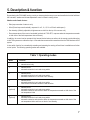
OPERATING INSTRUCTIONS Version 12/06 Automatic awning control ‘FS20 AMS’ Item no. 61 81 04 Introduction Dear customer, Thank you for purchasing this product. This product meets the requirements of both current national and European guidelines. In order to ensure continued fulfilment of legal requirements and safe operation of this product, we kindly ask you to carefully follow the instructions in this user manual! All company and product names contained herein are trademarks of their respective owners. All rights reserved. Should you have any further questions, please contact our technical service: Germany: Tel. no.: +49 9604 / 40 88 80 Fax. no.: +49 9604 / 40 88 48 e-mail: [email protected] Mon. to Thur. 8.00am to 4.30pm Fri. 8.00am to 2.00pm 2 Table of contents Page 1. Prescribed use ............................................................................................................................................... 4 2. Scope of delivery ........................................................................................................................................... 4 3. Explanation of icons ..................................................................................................................................... 4 4. Safety instructions ........................................................................................................................................ 5 5. Description & function .................................................................................................................................. 7 6. Preparation for operation, assembly .......................................................................................................... 9 a) b) 7. Installing the sensor unit (external sensor) ............................................................................................. 9 Installing the control unit ........................................................................................................................ 10 Programming/operation ............................................................................................................................. 13 a) b) c) d) e) f) g) h) Setting the operating mode ................................................................................................................... 14 Time settings (time, fixed retraction and extension time) ..................................................................... 14 Blocking interval times (wind, rain, sun intensity) ................................................................................. 15 Wind speed ............................................................................................................................................ 15 Motor runtime ......................................................................................................................................... 16 Sun intensity .......................................................................................................................................... 16 Additional function: Registering FS20 transmitters ............................................................................... 17 Operation ............................................................................................................................................... 18 8. Integrating the ‘FS20 AMS’ into the FS20 address system .................................................................... 19 9. Information on the range ............................................................................................................................ 20 10. Maintenance and cleaning ......................................................................................................................... 20 11. Handling ....................................................................................................................................................... 21 12. Disposal ........................................................................................................................................................ 21 13. Declaration of conformity (DOC) ............................................................................................................... 22 14. Technical specifications ............................................................................................................................ 22 3 1. Prescribed use This product is designed for the automatic weather and climate-dependent control of electric awning drives. Please see section ‘5. Description & function’. The entire product must not be modified or adapted, otherwise the guarantee/warrantee as well as the licence (CE) will become invalid. Any use other than the one described above may damage the product and can also increase the risk of short-circuit, fire, electric shock etc. Take note of all the safety instructions in this user manual! 2. Scope of delivery • Sensor unit • Control unit • User manual 3. Explanation of icons The icon with a lightning flash in a triangle is used to alert you to potential personal injury hazards such as electric shock. The icon with an exclamation mark in a triangle points to particular dangers associated with the handling, function or operation of the product. 4 The ‘hand’ icon indicates special tips and operational notes. 4. Safety instructions The product’s guarantee becomes invalid, if the product is damaged as a result of the failure to observe these operating instructions. We do not assume any liability for any resulting damages! Nor do we assume liability for damage to property or personal injury caused by improper use or failure to observe the safety instructions. In such cases the product’s guarantee becomes invalid! Dear customer, The following safety instructions and danger warnings are designed to protect you as well as the device. Please take time to read through the following points: • Do not use this product in hospitals or medical institutions. Although the FS20 wireless control system (to which the ‘FS20 AMS’ awning control also belongs) only emits relatively weak radio signals, these may cause life-support systems to malfunction. This may also be the case in other areas. • For safety and licensing (CE) reasons any unauthorised alterations to and/or modification of the product are not permitted. • The product is designed in accordance with protection class I. Voltage/power may only be supplied via the public power supply (230V~/50Hz). • This product is not a toy. Devices operated via the supply voltage should be kept out of the reach of children. Therefore, take particular care when children are around. Children are unable to appreciate the dangers associated with electric current. • Do not leave packaging material lying around. This may become a dangerous plaything in the hands of children. • The sensor unit is designed for permanent use in unprotected outdoor areas. The same applies to the control device, provided that it has been professionally and properly installed. • In order for the control unit to be connected to the supply voltage and the consumer load or loads work needs to be carried out on the supply voltage or on live voltage-carrying parts. Please note: Only people who are appropriately trained are permitted to carry out work on voltage-carrying parts. If you are not appropriately trained, please consult a qualified electrician who is authorised to carry out such work. • Before opening the control unit make sure you disconnect the unit from the supply voltage (all poles). Make sure you do the same for all the consumer loads that are to be connected or are already connected. Ensure that the supply voltage cannot be switched on by a third party while this work is carried out. This can be done, for example, using mechanical security fixtures and additionally using conspicuous warning signs. • Always insert and screw in the display and control circuit board before switching on the supply voltage again. 5 • Make sure you only load the product up to the capacity indicated. An overload may lead to the destruction of the device, a fire or an electrical accident. • Do not use inadequate power cords. These should be sized according to the load to be connected. • Only rigid installation cables that are designed for fixed installations may be connected to the device. Always apply suitable wire-end sleeves when using flexible cables. The device must be securely attached within a fixed installation (for example, wall mounted using screws/dowel). • Only VDE-approved supply voltage buttons should be used as external buttons, as these have direct contact to the supply voltage. Only VDE-approved insulated cables and consumer loads should be connected to the terminals KL3 and KL4. • The accident-prevention regulations, established by the Employer’s Liability Insurance Association for electrical equipment and facilities, must be adhered to in commercial facilities. • Responsible supervision must be provided by trained personnel when the product is used in schools, training centres, do-it-yourself and self-help workshops. • Never operate the product near or in the vicinity of inflammable liquids or gases, air/gas mixtures (petrol fumes) or easily inflammable solids. When the product is operated sparks may be generated that could cause gases or gas-air mixes to ignite. Danger of explosion! • Only use the device in moderate climates and never in tropical climates. • Consult a skilled technician if you have doubts about the mode of operation, safety or connection of the device. • Handle the product with care; knocks, blows or even a fall from a low height can damage it. 6 5. Description & function By purchasing this ‘FS20 AMS’ awning control you have acquired an easy-to-use and versatile device that facilitates the automatic, weather and climate-dependent control of electric awning drives. Weather and climatic factors: • Rain (response when it starts to rain) • Wind (5-level response threshold), response for a 5, 10, 15, 20 or 25 km/h wind speed ) • Sun intensity (infinitely adjustable; brightness sensor built into the top of the sensor unit) • Room temperature of the room to be shaded (optional via ‘FS20 STR’, response when the temperature exceeds or falls short of the limit temperature that can be set) In addition, the control can be operated via its internal device buttons as well as via the remote controls belonging to the FS20 system over a distance of up to 100m and other remote switch transmitters from the FS20 wireless control system. A time switch function for automatically extending and retracting the awning at fixed times is available as a further control option. The following operating modes are available: Table 1: Operating modes Mode Function 1 - manual control only 2 - manual control - automatic retraction in rain and strong winds 3 - manual control - automatic retraction in rain and strong winds - automatic extension for a set level of sun intensity 4 - manual control - automatic retraction in rain and strong winds - timer switch for automatic extension and retraction 5 (optional) - manual control - automatic retraction in rain and strong winds - automatic extension and retraction when the temperature exceeds or falls short of the set temperature limits 6 (optional) - manual control - automatic retraction in rain and strong winds - automatic extension and retraction when the temperature exceeds or falls short of the set temperature limits and for a set level of sun intensity 7 All the programmed data is permanently stored in the device’s integrated memory even when a power outage occurs, the programmed device is stored and not connected to the power supply or when the power supply is changed. Please note: These operating and assembly instructions only apply when the control is integrated into standard awning electronics. We cannot be held responsible, if the device is used differently than described here! 8 6. Preparation for operation, assembly Firstly, disconnect the existing power supply connection (all poles)! Deactivate the circuit breaker in use as well as the fuse. Use a suitable measuring device to measure and check that the supply voltage for the existing power supply connection really has been switched off. Only afterwards can you start to assemble the device. Before assembling and using the device, make sure you take note of all the safety and assembly instructions in this user manual. Only people who are appropriately trained are permitted to carry out work on voltage-carrying parts. If you are not appropriately trained, please consult a qualified electrician who is authorised to carry out such work. Any incorrect work carried out on the supply voltage may lead to a fatal electric shock. You endanger not only your own life but also the lives of others! Two important factors play a part in determining a suitable installation location: • Any cabling that may already exist • Good radio reception (when using an additional wireless remote control from the FS20 wireless control system) We therefore recommend that you test the radio reception at the installation location. a) Installing the sensor unit (external sensor) When selecting an installation location for the sensor unit you should make sure that the unit is installed close to the awning so that it can analyse the weather directly at the ‘event location’. Here, you also need to ensure that the precipitation can fall directly onto the rain sensor without being obstructed (for example, by a roof projection, leaves etc.), and that the anemometer can take in the air current from all sides, as, at ground level, the wind direction can change quickly. Therefore a free-standing attachment to a small mast is just as ideal as mounting the device to a roof projection. Proceed as follows to install the sensor unit: 1. Mount the sensor unit at the selected installation location as described above. Make sure that the drill holes or screws do not damage any cables, power supply lines, gas pipes, or similar! Life-threatening danger! 2. Make sure you do not bend, pinch or run the cables over any sharp edges. Fix the cable going to the control unit in accordance with the local conditions directly from the mast outlet. Ideally you should use a wiring conduit, however, you can also use cable clips. 9 3. Attach the anemometer as far as it will go on the axis, which is located on the tip of the sensor unit, and secure it to the flattened side of the axis using the respective screw. 4. Check that the rain sensor is firmly attached. 5. Once the sensor unit is mounted, the cable to the control unit can be laid and, if necessary, be shorted to the required length. b) Installing the control unit When selecting an installation location for the control unit choose a location where, on the one hand, the unit will be protected from any unauthorised access and, on the other hand, the unit can be easily wired to the existing control cables of the awning motor. The cable connecting the sensor unit and the control unit should not exceed 10 m. Proceed as follows to install the control unit: 1. Open the awning control by removing the casing cover (4 screws). Never touch the transmitter board on the right of the control circuit board and do not ‘straighten’ any of the components. 2. Attach the casing to a wall using four screws, and, if necessary, dowels. Make sure that the drill holes or screws do not damage any cables, power supply lines, gas pipes, or similar! Life-threatening danger! 3. Loosen the four screws on the display and control circuit board and move the board upwards, keeping it straight and without tilting it. To release from the plug connector use a pair of flat-nose pliers to pull the solder lugs located on the right both above and below the display. Be careful not to damage the circuit board! 4. Run the three cables (power cord, motor cable and sensor cable) separately through the three screwed cable glands and connect the cables to the sensor (KL1 and KL2), to the awning drive (KL4) and to the power supply (KL3) according to the connection circuit below. Cables with a specified minimum diameter must be used in order to ensure that the screw couplings are water-tight! 10 Connection of supply voltage, awning drive motor and sensor to the control: SI 1 315 mAT L N PE PE N LI LII KL1 KL 2 +UB GND Regen Wind Sonne KL4 Aus Ein KL3 PE N L N PE ws gr 1 2 br gn ge 3 1 Connection to the supply voltage 2 Motor (v = retract, u = extend) 3 Sensor connections wh gy br gn ye white grey brown green yellow supply voltage +UB earth GND rain sensor wind sensor sun sensor Standard circuit for simple awning electronics (rocker switch on the left of the diagram, 2 buttons on the right of the diagram): L N PE L 11 Please also note: The drive motor is connected completely via KL4. If a power supply connection to the motor already exists (the standard circuits for awning electronics are shown at the bottom of the adjacent diagram), then this must be disconnected and the cables N, PE and LI (extend) and LII (retract) must be wired according to the connection circuit. If necessary, an existing power supply connection for the awning drive can be used as the power supply for the control. Carefully observe the wire colour codes for the sensor cable. The control cable or extend button is identified in the connection diagram by an arrow that points downwards, while an arrow that points upwards identifies the retract button. 5. Now screw in the cable bushings so that the inner rubber seals lie firmly against the cable (a specified minimum cable diameter is required here!) and carefully reinsert the display and control circuit board. Make sure that the contact strip’s pins are correctly inserted into the respective socket terminal strip on the lower circuit board. Do not exert any force! Be careful not to tilt the circuit board. Then attach the upper control circuit board using the respective four screws. The product may only be operated or tested once the display and control circuit board has been fully inserted and screwed in. 6. Now you can switch on the supply voltage. Now you need to program the device. See the following section. 7. Once you have programmed the control replace the casing cover and fasten it using the four screws. Be careful to make sure that the cover’s rubber seal sits in its groove properly and does not get pinched when you screw on the cover. Otherwise moisture may get into the control unit when it is used outdoors, which could result in a lifethreatening electric shock! 12 7. Programming/operation All the program settings are stored in the device and protected against power failure. This means that you are not required to reprogram the device in the event of a long-lasting power failure. Please note: For all switching operations a safety/switching delay is always introduced between the switch-off of one relay and the switch-on of the other relay in order to prevent both relays from being switched on at the same time and thus avoiding potential short-circuits. You can program the following criteria for the control (each of the respective display indicators are shown in brackets): • Operating mode (MOD) • Time (UHR) • Automatic awning extension time (AUS) • Automatic awning retraction time (EIN) • Wind/rain blocking interval time (WRI) • Sun blocking interval time (SOI) • Manual blocking interval time (SPI) • Wind speed (WGS) • Motor runtime for full awning extension (MLZ) After initial operation and programming the time and current operating mode (to the right of the time) are displayed during normal operation. Control device’s button functions: Left button (TA1) = AUS (extend) Right button (TA2) = EIN (retract) When a remote control from the FS20 wireless control system is used this button assignment applies to the button combination used. The ‘Manual control’ and ‘Setting the operating mode’ functions can be controlled via the remote control. Please note: For all the settings the control automatically returns to normal operation after one minute, if no further button is pressed during this minute. 13 a) Setting the operating mode See table 1 in section 5. • Press the retract button (TA2) for approx. three seconds until the currently set mode appears on the right of the display. • Use the extend button (TA1) to select the operating mode you require. • Confirm your selection by pressing the retract button (TA2). • The device returns to normal operation (time display). The newly set mode now appears on the right of the display, for example, M5. b) Time settings (time, fixed retraction and extension time) • Press the retract button (TA2) for around five seconds until the time display appears. • Release the button. The hour indicator blinks. • Keep pressing the extend button (TA1) until the required hour is displayed. • Then press the retract button (TA2). The minute indicator now blinks. • Keep pressing the extend button (TA1) until the required minute is displayed. • Then press the retract button (TA2). The hour indicator blinks again and ‘AUS’ appears on the right. Now you need to enter the fixed awning extension time. Of course you can only activate the fixed awning extension and retraction time in the relevant operating mode 4. • Keep pressing the extend button (TA1) until the hour for the required extension time is displayed (for example, ‘10’ for 10:45). • Then press the retract button (TA2). The minute indicator now blinks. • Keep pressing the extend button (TA1) until the minute for the required extension time is displayed (for example, ‘45‘ for 10:45). • Then press the retract button (TA2). The hour indicator blinks again and ‘EIN’ appears on the right. Here you enter the fixed awning retraction time. • Keep pressing the extend button (TA1) until the hour for the required retraction time is displayed (for example, ‘20‘ for 20:15). • Then press the retract button (TA2). The minute indicator now blinks. • Keep pressing the extend button (TA1) until the minute for the required retraction time is displayed (for example, ‘15‘ for 20:15). • After completing your entries press the retract button (TA2) once. • The device returns to normal operation. 14 When operating mode ‘4’ is selected the awning extends and retracts at the programmed times. c) Blocking interval times (wind, rain, sun intensity) The blocking interval times determine the intervals after which automatic operation can be resumed after an action has been carried out. The wind/rain and sun blocking interval time stops the awning from constantly extending and retracting during unsettled weather conditions, fast-moving clouds or short rain showers. The respective blocking time is activated by the allocated sensor. The manual blocking interval time has the highest priority and is activated after manual intervention in the control via one of the two buttons or a wireless remote control from the FS20 system. The range of 1 - 59 minutes can be used for all the settings. • Press the retract button (TA2) for approx. seven seconds until ‘WRI’ appears on the right of the display (this stands for ‘wind/rain blocking interval time‘). • Keep pressing the extend button (TA1) until the blocking time you require is displayed. • Then briefly press the retract (TA2) button again. ‘SOI’ (‘sun blocking interval time’) now appears on the right of the display. • Keep pressing the extend button (TA1) until the blocking time you require is displayed. • Then briefly press the retract (TA2) button again. ‘SPI’ (‘manual blocking interval time’) now appears on the right of the display. • Keep pressing the extend button (TA1) until the blocking time you require is displayed. • After completing your entries press the retract button (TA2) once. • The device returns to normal operation. d) Wind speed You must select a maximum wind speed for the awning so that when this speed is reached the awning retracts. The speed depends on the design of the awning, how it is mounted and its size. You can set five different levels (5-10-15-20-25 km/h). • Press the retract button (TA2) for approx. nine seconds until ‘WGS’ (‘wind speed’) appears on the right of the display. • Keep pressing the extend button (TA1) until the wind speed you require is displayed. • After completing your entries press the retract button (TA2) once. • The device returns to normal operation. In operating modes 2, 3, 4, 5 and 6 the awning will retract when the set wind speed is exceeded. If the wind eases off, the awning can only be automatically extended after the specified wind/rain blocking interval has elapsed (see section c above). 15 e) Motor runtime As each awning requires a different amount of time in order for it to be fully extended or retracted, this time must be communicated to the control so that the latter can coordinate its automatic functions. • Fully retract the awning. • Press the retract button (TA2) for approx. 11 seconds until ‘MLZ’ (‘motor runtime’) appears on the right of the display. • Now press the extend button (TA1). The awning now starts to extend. The extension time is counted in seconds on the display. • Press the extend button (TA1) again as soon as the awning drive’s motor limit switch has switched off the motor. • The motor runtime has now been stored and the device returns to normal operation. f) Sun intensity The switching threshold selected here determines the point at which the awning should be extended, for example, when the threshold is reached or exceeded. Please note: f You can only set this switching threshold once the direct sunlight has reached the required intensity (brightness), for example, the sun has reached a particular meter reading. f Before setting the threshold retract the awning and select mode 3. f If a sun blocking interval time has been set, as described in section 7. c), then you must wait for this to elapse, after manually retracting the awning, before you can begin to set the switching threshold. If necessary, set a shortened time (for example, one minute). f To set the threshold set the sun blocking time to zero and turn the potentiometer, which is located on the left of the extend button (TA1), as far as it will go to the left. The sensitivity for detecting direct sunlight is now at its lowest and the control will not respond even in direct sunlight. • Now turn the potentiometer very slowly clockwise to the right until the awning starts to extend. At this point the required threshold for the current direct sunlight has been reached. Leave the potentiometer as it is. • The limit is now set and, in future, the awning will extend when this limit is exceeded. 16 In operating modes 3 and 6 the awning will now extend when the set limit is exceeded. Once you have made all these settings the control is ready for operation in its basic configuration. g) Additional function: Registering FS20 transmitters The awning control allows up to four FS20 transmitters to be registered, including the ‘FS20STR’ wireless thermostat. Proceed as follows to register a transmitter for the awning control: • Simultaneously press both buttons (TA1/TA2) for approx. three seconds until ‘COD’ appears on the right of the display. • Keep pressing the extend button (TA1) until the memory location you require has been selected ( 1-4). • Briefly press the retract button (TA2). The memory location indicator now blinks. • A button for the required channel should now be pressed on the remote control or for the ‘FS20STR’ the code needs to sent according to its operating instructions. Once the device has properly received the code it responds by returning to normal operation. • If required, you can repeat these programming steps to register a further FS20 transmitter to another memory location. • You can overwrite a memory location with a new code at any time by reprogramming it. Deleting a memory location • Simultaneously press both buttons (TA1/TA2) for approx. three seconds until ‘COD’ appears on the right of the display. • Press the extend button (TA1) as often as it takes until the required memory location (1-4) has been selected and hold the button down for approx. two seconds until the device returns to normal operation. • You have now deleted the required memory location. 17 h) Operation Once you have completed these programming steps the control does not need to be manually operated at all during normal operations. However, if required, you can still extend or retract the awning at any time using the remote control or the control buttons on the device. You can also partly open and close the awning via the manual control. Operation using the remote control • Retract You can retract the awning by briefly pressing the right button of the channel occupied by the awning control. • Extend Briefly press the left button to extend the awning. • Stop You can stop the awning at any position by briefly pressing one of the two buttons. • Direct mode The functions described for ‘Operation using the remote control’ can also be executed in the same way using the two internal buttons (TA1 - extend; TA2 - retract). 18 Always press the retract button for fewer than three seconds, otherwise you will activate a programming mode! 8. Integrating the ‘FS20 AMS’ into the FS20 address system The ‘FS20 AMS’ can be integrated into the address system of the FS20 wireless control system via the latter’s addressing scheme using single addresses, function groups, local and global masters. More detailed information on exactly how this address system is structured is provided in the user manual of each transmitter belonging to the FS20 wireless control system. Up to four address types can be assigned to the ‘FS20 AMS‘ within the FS20 wireless control system’s address system. This makes it possible to operate the control remotely from several transmitters with the same or different address types. You can find more detailed information on the address system in the user manual of each remote control belonging to the system. To assign several address types to the ‘FS20 AMS’ repeat the programming steps described in section 7. g). You can create a list of up to four addresses or address types in the control’s memory. 19 9. Information on the range • The FS20 system works in the 868 MHz range, which is also used by other radio services. Therefore devices that operate on the same or neighbouring frequency may restrict both its operation and its range. • The specified range of up to 100 is the free-field range, which means, the range within visual contact between the transmitter and receiver. In practice, however, walls, ceilings, etc. between the transmitter and the receiver may affect and reduce the range. A device called a repeater is available in the FS20 system for increasing the range. The repeater receives the radio signals sent by the transmitters in the FS20 system and resends them after a short time. Other causes of reduced ranges: • All types of high-frequency interference • Any buildings or vegetation • Conductive parts that are located near the devices or within or near their transmission path can lead to field distortions and reductions. • The distance of the transmitter or receiver to conductive surfaces or objects (to human bodies or the ground as well) influences the range. • Broadband interference in urban areas can reach levels that diminish the signal-to-noise ratio, thus reducing the range. • Insufficiently shielded PCs can cause radiation that interferes with a receiver and reduce the range. Please note: Do not position several radio receivers directly next to each other as these can interfere with each other (minimum distance 0.2 m, we recommend 0.5 m or more). 10. Maintenance and cleaning This product does not require maintenance. However, you should occasionally clean the humidity sensor that can get dusty. Simply wipe it using a soft, clean cloth. Do the same for the control device’s casing. 20 Never use solvent-based cleaning agents as these may damage the surface of the plastic casing and its inscription (also, the surface of the humidity sensor could be damaged). 11. Handling Take note of all the safety instructions in this user manual. Due to the way it is constructed the product can be used outdoors provided that the awning control’s casing is fully and correctly closed. At the same time the product must be assembled and wired properly and professionally. Caution, risk of life-threatening electric shock! Only people who are appropriately trained are permitted to carry out work on voltage-carrying parts. If you are not appropriately trained, please consult a qualified electrician who is authorised to carry out such work. Never use the product immediately after it has been brought from a cold room into a warm one. The condensation that forms could damage the device! Allow the device to reach room temperature before switching it on. This may take several hours. Make sure that the insulation of the entire product is neither damaged nor destroyed. Normally the awning control is installed once and then remains fixed at the installation location. Depending on the installation location, check occasionally if the product is in perfect condition. 12. Disposal Electric and electronic products must not be disposed of in the domestic waste. When the product is no longer usable dispose of it in accordance with the applicable statutory regulations. 21 13. Declaration of conformity (DOC) We, Conrad Electronic, Klaus-Conrad-Straße 1, D-92240 Hirschau (Germany), hereby declare that this product complies with the fundamental requirements and other relevant regulations of directive 1999/5/EG. You can find the declaration of conformity for this product at www.conrad.com 14. Technical specifications Operating voltage: ............................................... 230V~, 50Hz Power consumption: Stand-by: .............................................................. 10mA Relay on: .............................................................. 20mA Breaking capacity: ............................................... max. 3680VA (230V~/16A) Dedicated sensors: .............................................. KS200; FS20 rain sensor Wind limits: ........................................................... 5, 10, 15, 20 or 25km/h Reception frequency: .......................................... 868.35MHz Modulation: .......................................................... AM Range: .................................................................. up to 100m (free-field) Dimensions (W x H x D): ..................................... 160mm x 55mm x 80mm 22 23 http://www.conrad.com Imprint These operating instructions are published by Conrad Electronic SE, KlausConrad-Str. 1, D-92240 Hirschau/Germany. 100% recycling paper. Bleached without chlorine. No reproduction (including translation) is permitted in whole or part e.g. photocopy, microfilming or storage in electronic data processing equipment, without the express written consent of the publisher. The operating instructions reflect the current technical specifications at time of print.We reserve the right to change the technical or physical specifications. © Copyright 2006 by Conrad Electronic SE. Printed in Germany.