1
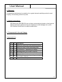
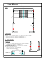
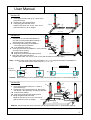
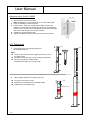
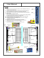
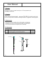
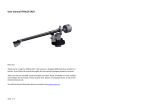
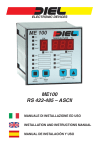
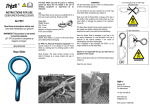
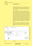
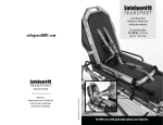
User Manual
Please read and file this user manual carefully.
Reproduction and distribution to unauthorized parties
forbidden. Technical details are subject to change!
Number: 33318E
Date: Nov.2006
Assembly Schedule
Beachvolleyball – Game Posts
PRO BEACH
Item No. 56848, 56850, 56860
Design Marking
1A
2A
1B
2B
Game post PRO BEACH
with Special - Groundsockets for
bolding
Adhesive achor (with anchor rod M10)
Game post PRO BEACH
with Switch - Special - Groundsocket
linked to the floor panel for bolding
BEACH – floor panel for bolding
Adhesive achor (with anchor rod M10)
Game post PRO BEACH
with CITY – BEACH – Groundsocket
linked to the wooden square timber
Square-Timber-Set (4-parts)
Game post PRO BEACH
with Switch - Special - Groundsocket
linked to the floor panel with T-base and
wooden square-timber
BEACH – floor panel with T-base for
Switch - System
Square timber-Set (4-parts)
Item No.
56850
56852
Remark:
Test symbol
only for
Art.Nr.:
56860.
56848
50788
56852
56860
50774
56848
50789
50774
Remark: Article without net, post pad, adhesive achor
and additional mountings.
1
User Manual
Content
1.
2.
3.
4.
5.
6.
7.
8.
9.
10.
11.
12.
13.
Product Description.................................................… Page 2
Intended Use........................………………………….. Page 2
Warranty...............................................................….. Page 3
Safety Instructions................................................….. Page 3
Components Lists and Image.................................…. Page 3-4
Assembly and Maintenance
6.1. Groundsocket (Adhesive achor)...................…. Page 4-6
6.2. Game post...................................................….. Page 6
6.3. Bachvolleyball – competition net....................... Page 7
Storage...................................................................…. Page 8
Cleaning...................................................................... Page 8
Maintenance................................................................ Page 8
Spare parts…………………......................................... Page 8
Accessories................................................................. Page 9
Technical Data.......................................................…. Page 9
Contact Details......................................................….. Page 9
Explanation:
Remark:
Note :
Warning:
Additional information on the product.
Imminent danger for the product.
Imminent danger for a person.
1. Product Description
Beachvolleyball – game post PRO BEACH, powder-coted in yellow and
alumina-specialprofile 91x91 mm.
One game post with integrated pully block net tensioning device,
the other with counter slide.
Net heights and posts at fully tensioned net (100 kg).
Beachvolleyball – game post PRO BEACH with CITY – BEACH - groundsocket
(Art.Nr.: 56860) has a GS- and DVV1-test symbol.
2. Intended Use
Beachvolleyball – game post PRO BEACH can only be constructed and
used on level ground.
It can only be used in ball games.
In case of improper use or utilization by unauthorized persons, the liability expires
(ie. our warranty is no longer valid).
2
User Manual
3. Warranty
Provided that maintenance is carried out in regular intervals and the product is used
properly, the warranty period is 2 years.
4. Safety Instructions
Game post PRO BEACH can only be constructed and used on level ground.
No load can be placed on the net, because it could damage net or post.
Children should never be without subervision.
5. Components Lists and Image
Components List
Pos. Qty. Description
(1)
1x
Game post with pully block tensioning device
(2)
2x
Game post with counter tensioning slide
(3)
1x
Groundsocket – depending on design -
(4)
8x
Adhesive achor (not included in shipment)
(5)
2x
(6)
2x
Square-Timper-Set (not included in shipment)
BEACH – floor panel - depending on design -
(7)
1x
(not included in shipment)
Net (not included in shipment)
3
User Manual
Image
10/11 m
counter slider
tensioning slide
(1)
(7)
(2)
(3)
6. Assembly
Remark: Selection of distance between posts depends on the size of the field:
Size of the field 9x18 m
distance between posts 11 m
Size of the field 8x16 m
distance between posts 10 m
6.1. Groundsocket
Version 1A
1. Preparation of foundation 80x80x80 cm with concrete quality B25
including a Steel-mat (Q131) at a depth of 5cm.
2. Positioning and bolding of the groundsocket (3) on foundation.
4 per adhesive achor (4)
3. Filling the game field with sand,
Height of the sand: min. 25 cm, max. 50 cm
(UK red marker on 40 cm height)
10 / 11 m
foundation
80x80x80 cm
4
(3)
10 / 11 m
(4)
(3)
User Manual
Version 1B
(3)
1. Insert Square-timber-Set (5) in T-base of the
groundsocket (3).
2. Positioning of the groundsocket.
3. Filling the game field with sand,
Height of the sand: min. 25 cm, max. 50 cm
(UK red marker on 40 cm height)
(5)
T-base
10 / 11 m
Version 2A
(3)
1. Preparation of foundation 80x80x80 cm
(3)
only with concrete quality B25 including a
drilling
Steel-mat(Q131) at a depth of 5cm
2. Positioning and bolding of the BEACH
(6)
– floor panel (6) on foundation.
4 per adhesive achor (4)
bolt
3. Insert groundsocket (3) in BEACH – floor panel (6)
and use bolt for security.
Insert bolt into drilling.
10 / 11 m
Plug spring cotter through drilling in bolt.
spring cotter
10,1 / 11,1 m
4. Filling the game field with sand,
Height of the sand: min. 25 cm, max. 50 cm (UK red marker on 40 cm height)
Note: Distance from centre until centre foundation is 10 / 11 m, however dinstance of the BEACH –
floor panel (6) to each other must be 10,1 / 11,1 m.
10 / 11 m
foundation
80x80x80 cm
10,1 / 11,1 m
(6)
(6)
(4)
Remark: Border strip and cover of the floor panel can be found under point 11. Accessories (page 9).
Version 2B
(3)
(3)
1. Insert Square timber-set(5) into T-base of
groundsocket (3).
2. Positioning of the groundsocket (3), then insert
Into Beach – floor panel (6), and secure with bolt.
Insert bolt into drilling.
Plug spring cotter through drilling in bolt.
3. Filling the game field with sand,
Height of the sand: min. 25 cm, max. 50 cm
(UK red marker on 40 cm height)
T-base
drilling
(6)
bolt
spring cotter
10 / 11 m
Remark: Border strip and cover of the floor can be found under point 11. Accessories (page 9).
Remark: Dispose of the packaging materials according to the regulations prevailing in your country.
5
User Manual
Adhesive achor (Art.Nr.: 56852)
1. Drill and clean a hole for the bold.
Note: Installation is only permissable in concrete quality B25.
2. Inser the cartridge into the borehole.
3. Fit the UPAT – setting or socket wranch SW12 into the drill
hammer or percussion drill. Attach the anchor rod an charge by
vibration up to the mark, then immediately switch off the machine
and remove the setting tool from the machine.
4. Postitioning of the groundsocket.
5. Tighten the adhesive anchor with hex-nut and disc to 80 Nm.
flush floor
6.2. Game post
1. Insert game post (1/2) into the opening of
the groundsocket (3).
(1/2)
(1/2)
Note:
The two rolls on the end of the game post have to be on
top (upper side).
Consider the position of the posts to the groundsocket.
Game post is held by rubber cables,
suspended through a 10 cm long range.
(3)
2.
Infinite height adjustment of game post (1/2)
Loosening of the fixing screw.
Positioning of the game post in desired height.
Thightening of the fixing screw.
(1/2)
fixing screw
6
(3)
User Manual
6.3. Net
counter
slide
1. Guide one end of the tensioning cable (A) over the deflection roller and
suspend it in the carbine clip.
2. The other cable end (B) has to be pulled over the opposite deflection
roller and attached to the snap hook fo the button-hole strap.
3. Pull the button-hole strap down (for pre-tensioning the net) and insert it
into the hook.
4. Pull the cordof the adjustment slide.
The lamella brake will clamp down the cord under tension, therby allowing
to create the necessary net tension in several steps. .
5. Use the tensioning cord to fix the button cable (C + D) on the hook.
6. Use the tensioning cord to centre the net.
Thread the tensioning cord through the eye and pull it completly
Througth the button hole.
Suspend the other end of the tensionion cord into the
deflection roller/ hook or noose it around the post and knot it.
7. The additional slide can be moved up or down
by the socket wranch.
tension
slide
eye
tensioning cord
(A)
tension
slide
deflection slide
deflection slide
(A)
counter
slide
(B)
carabiner
hook
carabiner
hook
pretansioning
cord
tansioning cord
hook
lamella
break
tansioning cord
string
(D)
(C)
hook
hook
additional slide
pre-tansioning
cord
additional slide
(C)
tansioning cord
socket wranch
7
User Manual
7. Storage
Storage has to be in a closed room by min. 15°C tem perature and
a humidity of max. 65%.
8. Cleaning
Please clean the Beachvolleyball - game post PRO BEACH only with a moist cloth.
Do not use any caustic chemicals, cleaning solutions or aggressive cleaning agents.
9. Maintenance
Check net and carabiner clip for deformation and damage.
Make sure that cord and tensioning cable are undamaged.
Check groundsocket and game post for damage.
10. Spare parts
Pos. Description
(10) Polyamid-cord Ø5 – length: 3,5m
in tensioning slide of the tensioning device
(11) Round cord Ø8 in post
tension slide
Item No.
K0320001
K0320161
(1/2)
(10)
(3)
(11)
8
User Manual
11. Accessories
Covering for Version 2A and 2B
for Switch - System for bolding, Art.Nr. 50794
Border strip for floor panel for Version 2A
for Switch - System for bolding, Art.Nr. 50852
Border stip for floor panel for Version 2B
for Switch – System, free standing, Art.Nr. 50795
Beachvolleyball – competition net
according FIVB, Kevlar tensioning cord and
2 Isi-Link-tensioning cords,
length: 8,50 m, Art.Nr. 50739
12. Technical Data
Game post (Art.Nr.: 56848, -50, -60)
Profile: 91 x 91 mm
Height: ca. 216 cm
Groundsocket:
Groundsocket Switch (Art.Nr. 56848) with
BEACH – floor panel for bolding (Art.Nr. 50788)
total height: 120 cm
Groundsocket Switch (Art.Nr. 56848) with
BEACH – floor panel with T-base (Art.Nr. 50789)
total height: 130 cm
Groundsocket for bolding (Art.Nr. 56850)
total height: 120 cm
Groundsocket CITY-BEACH (Art.Nr. 56860)
total height: 128 cm
Square timper – Set, set of 4 (Art.Nr.: 50774)
Profile:
9x9 cm
2 timper of 295 cm lenght
2 timper of 145 cm lenght
13. Contact Details
Phone:
Fax:
E-mail:
Internet:
Postal Address:
++49 / 9861 / 406- 44
++49 / 9861 / 406- 616
[email protected]
www.erhard-sport.de
ERHARD Sport International GmbH & Co. KG
PO Box 1163
91533 Rothenburg o.d.T.
MO thru THU:
FRI:
7.30-16.30 hrs
7.30-12.30 hrs
Delivery Address:
ERHARD Sport International GmbH & Co. KG
Oberer Kaiserweg 8
91541 Rothenburg o.d.T.
9