1
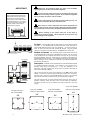
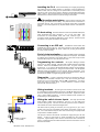
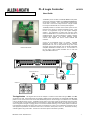
PL-8 Logic Controller
AP5270
User Guide
For PL-8 units manufactured after November 2004
The PL-8 is part of the Allen & Heath PL Series of wall plates
and remote controllers available for the iDR-4 and iDR-8 audio
mix processor systems. It is a small module comprising two
circuit cards. This can be locally mounted in a single unit wall
box using the standard UK, EU or US face plate supplied.
The PL-8 provides four contact closure switch inputs and four
transistor logic outputs for external equipment control. Their
function is programmed using the iDR System Manager
software. The combination of switch input and logic output
makes the PL-8 ideal as a multi-function remote controller in
installed systems. The unit can interface to a variety of devices
including alarm systems, room divider switching, paging
controls, event triggers and various custom switches and
indicators.
Control can be distributed where it is needed. The PL-8
interfaces via the Allen & Heath PL-Anet serial network.
Multiple PL-8 units can be daisy-chained using CAT5 cable
along with other PL-Anet devices such as the PL-3 and PL-4
wall plates, PL-6 fader controller and so on. For information on
the full range of PL products available visit our web site
http://www.allen-heath.com.
Internal view shown
ALARM OVERRIDE
DR-8
AUDIO MIX PROCESSOR
PL-Anet
PL-8
AUDIO
ROOM DIVIDER SWITCHES
PAGING MIC
CUSTOM SWITCHES AND INDICATORS
TERMINATION
PL-6
PL-8
PL-4
SELECT AND TALK SWITCHES
PL-3
The Application The diagram above shows an example of a remote control network using an iDR-8. The iDR4 could also be used. Various PL devices are installed in different parts of the building, for example PL-3 and PL-4 wall
plates for room volume control and source select, PL-6 fader panel for remote mixing in a conference room, and PL-8
units for distributed remote control. The PL-8 could be wired to a fire alarm system to automatically mute the system
or override it with a pre-recorded evacuation announcement, to simple wall plate switches for local volume control or
event configuration changes, to paging panels for zone select and talk switching, to room divider panel microswitches
to automatically reconfigure the system when rooms are combined, to control or be controlled by equipment such as
video players and jukeboxes, for interractive local sound in museums, theme parks, and so on. The devices are daisychained together using CAT5 cable. The last unit in the chain requires a terminator (provided).
PL-8 User Guide AP5270 issue 3
1
Observe the local standards which may apply to the installation
regarding the grade of cable and installation methods.
IMPORTANT:
To ensure operator safety ensure that any exposed metal face plates
and surfaces are correctly bonded to ground. Do not install the equipment
where it is subject to moisture, heat or vibration.
Note: PL-8 Units manufactured prior
to November 2004 were fitted with
5way terminal blocks with a single
ground terminal, rather than the
7way version used on later models
as described below. If you require
any more information on the earlier
models, please contact Allen &
Heath technical support.
Connect this equipment to the Allen & Heath PL-Anet port only. Do
not connect it to Ethernet, DR-Link or other RJ45 ports.
When wiring to custom components and external equipment care
must be taken to ensure each part operates within its specified capability.
This work should be carried out by competent installation personnel only.
1 2 3 4 G
IN
GND
Before powering up the system make sure all the wiring is
inspected and continuity tested. This is important as wiring errors may
result in damage to the equipment.
AG5258_1
1-4
IN
PL-8
TOP
PL-8 early type connector block.
PL-ANET
DR-LINK
CAUTION 20V DC
TO AVOID DAMAGE ONLY CONNECT
COMPATIBLE REMOTE CONTROL
EQUIPMENT TO THE PL-ANET PORT.
AUDIO IN
AUDIO OUT
DIGITAL EXPANDER
CUSTOM WIRING
1-4
OUT
the PL-8 comes supplied with two PCB assemblies attached
to a brushed aluminium wall plate. This enables it to be mounted into a
standard single gang wall backing box. A UK, EU (European) or US
(American) size plate together with fixing screws is provided according to
which version has been ordered.
OUT
5-7
GND
1 2 3 4 GGG
PL-Anet
SWITCH IN
IN
OUT
IN
5-7
GND
1-4
IN
The top PCB houses the circuit which interfaces to the iDR PL-Anet control
network. Connection is made using two RJ45 type sockets, one to receive PLAnet, the other to pass it on to the next PL device in the chain. If this is the last
device in the chain then the terminator plug provided must be plugged in.
The lower PCB houses the screw terminal blocks which are used to wire to
switches, indicators, relays and other custom controls within the installation.
One block connects to up to four switches, the other provides up to four logic
outputs.
CUSTOM WIRING
TO NEXT PL DEVICE
OR TERMINATOR
Number of devices The maximum number of PL devices that can be
connected depends on their type and the distances involved. You can connect
up to 15x PL-8 units on a single PL-Anet branch, and up to 23 if you are using
the optional PL-9 PL-Anet hub. Fewer may be connected if long distances or
additional PL types are involved. It is important that you check the possibilities
first by referring to the PL Combinations Calculator spreadsheet available from
the Allen & Heath web site.
Description
LOGIC OUT
1 2 3 4 GGG
PL-Anet is the proprietary Allen & Heath system for daisy chaining remote
controllers. It is an RS485 serial connection that uses CAT5 STP cable to
communicate between devices over long distances. An RJ45 connector is
used. PL-Anet only works with Allen & Heath PL devices. The port provides
+20V DC to power the connected devices. The iDR-8 port is shown here.
FROM PREVIOUS PL DEVICE
Order code PL-8/US
UK single backing box
part number AA5220
Order code PL-8/EU
Plate part number AA5276
Plate part number AA5275
UK
UK
86
72 x 72 x 35 mm
Order code PL-8/UK
60.3
86 mm
Plate part number AA5277
US
EU
80
60
113.5
83.4
80 mm
69 mm
2
PL-8 User Guide AP5270 issue 3
Installing the PL-8 Mount the assembly into a single gang backing
box located in a wall or suitable furniture. If necessary, it may be installed in a
hidden location such as a ceiling void or cupboard as it is not necessary for the
operator to have access to the module. Minimum recommended internal box
depth is 32mm. We recommend that you provide enough space in the cavity
behind the box to allow a service loop for the wiring to the module.
Grounding metal plates Ensure that the metal face plate
is correctly grounded to ensure safety. The plate should be connected to a
local safety ground. Use a ground wire or physical contact with a grounded
back box. The same applies to any exposed metal surfaces used within the
system.
PL-Anet wiring Use flame retardent CAT5 STP (shielded twisted pair)
cable terminated with RJ45 connectors. Do not use UTP cable. We
recommend the multi-stranded rather than solid conductor type.
The
connection follows the EIA/TIA 568B wiring colour scheme. Ensure all ports
and cables in the system are wired to this scheme.
Connecting to an iDR unit The iDR unit communicates with
the PL-8 using the PL-Anet port. This serial connection can be daisy chained
through several PL wallplates as shown. Make sure you plug the PL-Anet IN
and OUT sockets correctly.
PL-Anet
End of chain termination
IN
TERMINATOR PLUG
As with any RS485 system, the last PL
device needs to have a terminating resistor fitted to its output port. Each PL-8
is shipped with a terminator plug already fitted in its PL-Anet output socket.
Leave this fitted only if the unit is the last in the chain.
OUT
IN
OUT
Programming the controls iDR System Manager software
version V3.1 or later is required. Check the Allen & Heath web site for the latest
software. Ensure that the iDR PL-Anet port is active. Its green ‘active’ LED
should be lit. If not, use the iDR System Manager software Communications
Option menu to activate the port. Plug in the PL-Anet cable. The iDR System
Manager screen should display icons for each PL device it recognises. If you
do not have the iDR available you can configure the software off line. Refer to
the Help file for details on programming the PL functions.
Diagnostics If a fault is suspected check the two diagnostics LEDs on
the underside of the PL-8 connector PCB. Both the red and green LEDs
should be lit once communication with the iDR is established. If a fault is
found, first check for correct wiring. If further assistance is required contact
Allen & Heath technical support.
Wiring terminals Phoenix type screw terminal connectors are used
for connecting the external switches and logic to the PL-8. Make sure the wire
ends are carefully stripped and inserted into the terminals. Tighten the screws
using a small slotted screwdriver. To ensure interference-free operation we
recommend you use shielded cable.
SWITCH
SWITCH
INPUTS
1 2 3 4
GG G
+5V
1K5
OPTO
INTERNAL PL-8 CIRCUIT
(1 OF 4 SHOWN)
PL-8 User Guide AP5270 issue 3
Wiring the switch closure inputs
The 7way input terminal
block provides 4 switch input connections. Pins 5 to 7 ‘G’ are used as the
common switch ground. One wire can feed this ground to a bank of switches.
Two switches are shown wired in the diagram here.
The switch works by linking its connector pin to any ground (‘G’) pin. Use a
contact closure such as a momentary press switch, microswitch or relay to do
this. Low current switches may be used. We recommend good quality sealed
components for reliable operation.
The input pin is fed from the internal +5V reference supply through a 1k5 ohm
resistor. It uses an opto-coupler to isolate the PL-8 from the connected
equipment. Approximately 1.2mA minimum current flows when connected to
ground. Combined switch and cable resistance should not exceed 1k ohm for
the switch to activate.
3
INTERNAL PL-8 CIRCUIT
(1 OF 4 SHOWN)
+5V
470R
SERIES RESISTOR
1 2 3 4 G G G
LED INDICATOR
TYPICALLY 6mA
Wiring the logic outputs
The 7way output terminal block
provides four logic output connections. Pins 5 to 7 ‘G’ are used as the
common return ground. One wire can feed this ground to a bank of indicators
or other devices.
The output works by switching the internal +5V reference supply through a 470
ohm resistor to the pin. This presents a positive voltage when the output is
turned on, and an open circuit when it is turned off. The switching is done
using a transistor. The resistor limits the current to a maximum 10mA to ensure
the connected equipment does not draw more than the PL-8 can provide.
The output may be used in many ways to satisfy a range of interfacing
applications. It is important that the installer has a good working knowledge of
interfacing circuits. Incorrect application may result in damage to the
equipment. Typical applications include powering an LED indicator and
switching solid state (low current) relays.
Specification
SWITCH
In/Out Connectors:
SWITCH
Phoenix 7way screw terminal blocks
For permanent bare wire connection
SWITCH
SWITCH
Switch Inputs:
4x opto-isolated switch closure inputs
+5V DC through series 1k5 ohm resistor
Switch closure connects pin to ground
Maximum current when switched = 1.2mA
Maximum switch+cable resistance = 1k ohm
Switch types:
Momentary action
Microswitch
Relay contact
Custom interface
PL-8
Communication:
RS485 based PL-Anet serial port
RJ45 input and output connectors
Maximium 15x addresses per PL-Anet branch
Configuration:
iDR System Manager software V3.1 or greater
Refer to the software Help file
Separately configure switches and outputs
Input switch function: Volume up/down
Mute on/off
Patch recall
Monitor select
Logic output function: Static on/off
Mute status
Soft switched
Patch recalls
Scheduled events
Power Supply:
Internal +5V DC from PL-Anet 20V supply
Minimum PL-Anet voltage at PL-8 = 11V
Maximum logic output = 40mA (all shorted)
4
GG
INPUTS
1K5
OPTO-ISOLATED SWITCH INPUTS
PL-Anet OUT
Logic Outputs:
4x transistor logic outputs
Uses internal PL-Anet supply
ON = +5V DC through series 470 ohm resistor
OFF = open circuit
Output voltage depends on current drawn
Maximum current per output (shorted) = 10mA
Output capability:
LED indicator
Solid state relay
Custom interface
1 2 3 4 G
PL-Anet IN
CONTROL
CHAIN
To next PL-Anet device
or terminator
+20V
From iDR or previous
PL-Anet device
+5V
LOGIC OUTPUTS
470R SERIES RESISTOR
OUTPUTS
1 2 3 4 G
GG
LED INDICATOR
LAMPS
MOTORS
EQUIPMENT
SOLID STATE +
RELAYS
-
DEVICE
This product complies with the European
Compatibility directives 89/336/EEC & 92/31/EEC.
Electromagnetic
NOTE: Any changes or modifications to the equipment not approved by Allen
& Heath could void the compliance of the equipment. Whilst we believe the
information in this guide to be reliable we do not assume responsibility for
inaccuracies. We also reserve the right to make changes in the interest of
further product development.
Copyright© 2005 Allen & Heath Ltd. All rights reserved.
PL-8 User Guide AP5270 issue 3