1
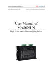
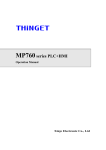
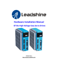
DP-504/DP-508 Stepper Driver User’s Manual Xinje Electronic Co., Ltd. NO. DC011 20091223 1.0 DP-504/DP-508 series subdivision driver user’s manual Content 1. Summary ....................................................................................................................................... 1 1-1. Characteristic ..................................................................................................................... 1 1-2. Application......................................................................................................................... 1 1-3. Electric characters .............................................................................................................. 1 2. Operation Guidance ...................................................................................................................... 2 2-1. Safety ................................................................................................................................. 2 2-2. Attention ............................................................................................................................ 2 2-3. Installation ......................................................................................................................... 2 3. Common Terminals ....................................................................................................................... 3 3-1. Control signal terminals ..................................................................................................... 3 3-1-1. Description of Control signals terminals ................................................................ 3 3-1-2. Sequential chart of control signal ........................................................................... 4 3-1-3. Input circuit ............................................................................................................ 4 3-2. Power Terminals ................................................................................................................ 5 3-2-1. Description of Heavy-current terminal ................................................................... 5 3-2-2. Requirement of power supply................................................................................. 5 3-2-3. Wiring ..................................................................................................................... 5 3-3. Function Setting ................................................................................................................. 6 3-3-1. Current Setting........................................................................................................ 6 3-3-2. Subdivision Setting................................................................................................. 7 3-4. Function for Protection ...................................................................................................... 7 4. Dimension installation and wiring ................................................................................................ 8 4-1. Dimension .......................................................................................................................... 8 4-2. Installation ......................................................................................................................... 8 4-3. Typical Wiring ................................................................................................................... 9 5. Malfunction Diagnoses and Solution .......................................................................................... 10 6. Motor Selection ........................................................................................................................... 11 i DP-504/DP-508 series subdivision driver user’s manual ii DP-504/DP-508series subdivision driver user’s manual 1. Summary DP-504/DP-508 subdivision stepper driver with 40VDC/80VDC input, 5.0A output is used for all the two- phase hybrid stepper motor whose rated current is below 5.0 A. Based on the pure sine wave current control technology, this series product have a good performance in smoothly running with low noise, meets the high resolution requirement of the numerical control equipments, such as laser marking machine, CNC machine etc. 1-1. Characteristic Low noise on motor running. Power supply reaches 40VDC/80VDC. Effective value of output current can up to 5.0A. Dynamic selection on subdivision with maximal value of 200. Matched all the 4/6/8 leads motor whose current is below 5.0 A. Photo isolator input signal. Easy-operation on current setting and selection by user. Over-voltage and over-current protection. 1-2. Application This series product can well meet the requirement of the small and medium automation devices and instruments, such as aerodynamic marking machine, labeling machine, cutting machine, laser marking machine, plotter, small carving machine, CNC machine etc., especially having a perfect performance on the devices which require low noise and vibration, high precision and speed. 1-3. Electric characters Item Min. value Typical value Max. value DP-504 20 36 40 DP-508 20 80 80 Effective value of output current 0 - 5 Logic input current (mA) 4 7 16 Stepper pulse frequency (KHz) 0 - 200 500 - - Power supply (VDC) Insulation resistance(MΩ) Ambient temperature 0℃~50℃ Max working temperature 70℃ Humidity 40%~90% RH (no condensation) Vibration 5.9m/s2 Max Storage temperature -20℃~65℃ Dimension 138mm×85mm×38mm 1 DP-504/DP-508 series subdivision driver user’s manual 2. Operation Guidance Please read the following suggestion carefully before you install the driver. 2-1. Safety The driver is authorized to be installed and operated by the professionals and technicians. Don’t turn on the power before you connect the motor. Make sure that the driver input meets the technical requirements. Don’t make the setting or measure operations on the motor and driver during power on. Please do the wiring, installation and parameter setting after power is off for more than 3 minutes. Ensure the connection operation is absolutely correct and fixable before you turn on the power, including the power wire, motor cable and signal cable. Avoid electromagnetic interference. 2-2. Attention Please use shield cable for signal input, and leave each other for distance. The further the distance, the better the interference is avoided. Please connect the motor cover to the GND terminal. Don’t operate on the output terminal when power on, or else the driver will be damaged. 2-3. Installation 2 Don’t install the driver next to the heat producing appliance. Don’t exposure the driver to the dusty, corrosive gas, elevated humidities, and advised to use with small vibration. For perfect conducting, please ensure the fixation between earth wire of host computer, driver, motor and ground. DP-504/DP-508series subdivision driver user’s manual 1 2 3 4 5 3. Common Terminals GND +V A+ AB+ B- 3-1. Control signal terminals 3-1-1. Description of Control signals terminals Signal Function Description PUL+ Pulse control signals Direction control signals Be available on the rising edge, motor moves a step at the rising edge of pulse turning from low- level to high-level. The direction of motor rotating changed by the turning of pulse between low-level and high-level .Once the pulse status is changed, the direction correspondingly turns. The original direction depends on the wiring of motor, which means the phase connection. Used for motor release. The stepper will not be active when ENA+ terminal connects to 24V and ENA- connects to low-level, in this case, the driver cuts off current of all phases and in free status, and also the temperature decrease. Otherwise, detaching the terminal means the motor is enabled all the time. PULDIR+ DIR- ENA+ Enable/release signal ENA- ERRO COM Malfunction signal output The malfunction signal is transferred by the ERRO and COM terminal when over-voltage or under-voltage. 3 DP-504/DP-508 series subdivision driver user’s manual 3-1-2. Sequential chart of control signal In order to ensure the reliability of the system response, please take the following advices. The high-level signal is effective when voltage is 24V; the low-level signal is effective when in the range of 0V to 0.5V. The ENA (enable) signal should be turned to high-level 3s before DIR (direction) signal or more. Ensure the falling edge of the DIR (direction) signal built 5μs before PUL (pulse) signal or more. The width of pulse should be more than 1.2μs The duration of the low-level pulse should be more than 1.2μs The sequential chart shows as below: 3-1-3. Input circuit The connection on common anode way of the diver input circuit is shown as below: Note: 4 The input signal should transfer by photoelectric isolation. Make sure the control DP-504/DP-508series subdivision driver user’s manual signal driven current is more than 8mA to keep the good conducting of the internal high-speed light-coupler. Light-coupler current limiting resistor is built in stepper driver. It is common to supply all the control signals with +24V. 3-2. Power Terminals 3-2-1. Description of Heavy-current terminal Terminal GND Function Description DC ground DC ground terminal terminal +V Anode terminal of DC To be on the value between Min. voltage and maximal voltage A+,A- A-phase of motor Direction of motor changed by the turning of A+ terminal and Aterminal. B+,B- B-phase of motor Direction of motor changed by the turning of B+ terminal and Bterminal. 3-2-2. Requirement of power supply Don’t connect the power supply terminal in reverse way. To keep the normal working of drive ,please ensure the power supply in this range: DP-504: 20~40VDC; DP-508: 20~80VDC It is advised to use non-regulated DC power supply, and make sure the current output of power is 60% higher than setting current on driver. Please ensure the current of power supply is higher than motor working current. 3-2-3. Wiring DC20~40V DC20~80V GND V+ A+ AB+ B- 2-Phase Step Motor Note: The motor performance depends on the connection between driver and motor. In most situation, the high-speed performance of motor is based on the power supply (the greater the power supply, the greater the high-speed torque, then avoid step missing), and the output moment is based on the setting current (the greater the setting current, the greater the output torque of motor). However, please pay attention that the motor is getting heat when the value of power supply is larger, and the vibration is obviously when the motor at a low speed. 5 DP-504/DP-508 series subdivision driver user’s manual Above all, please do the connection according to the requirement all the time. There are some typical connections for your reference as below: Parallel connection mode with 8-leads: the setting current value is 1.4 times than rated current on motor. Serial connection mode with 8-leads: the setting current value accounts for 50% of the rated current on motor. High-speed mode with 4/6 leads: the setting current value should be lower than the rated current on motor. High-torque mode with 6leads: the setting current value accounts for 70% of the rated current on motor. 3-3. Function Setting The setting of the full-current/half-current and subdivision precision is based on the status of 5-bits switch. The details are shown as below: SW1: Setting for half-current/full-current (SW1=OFF; half-current; SW1=ON; full-current) SW2~SW5: Setting the precision of subdivision. 3-3-1. Current Setting Set the current in the range of (0~5.0A) by single-turn potentiometers as below: 6 DP-504/DP-508series subdivision driver user’s manual 3-3-2. Subdivision Setting The precision of the subdivision is based on the status of 4-bits switch, as below: Subdivision multiple Steps/turn (1.8°/step) SW2 SW3 SW4 SW5 1 200 OFF OFF OFF OFF 2 400 OFF OFF OFF ON 4 800 OFF OFF ON OFF 8 1600 OFF OFF ON ON 16 3200 OFF ON OFF OFF 32 6400 OFF ON OFF ON 64 12800 OFF ON ON OFF 128 25600 OFF ON ON ON 5 1000 ON OFF OFF OFF 10 2000 ON OFF OFF ON 20 4000 ON OFF ON OFF 25 5000 ON OFF ON ON 40 8000 ON ON OFF OFF 50 10000 ON ON OFF ON 100 20000 ON ON ON OFF 200 40000 ON ON ON ON 3-4. Function for Protection Indicator LED Power indicator light: Green-light turning on means normal working. Alarm indicator light: An alarm is raised when red-light turns on which means over-voltage or over-current; the red-light flashing at regular intervals means over-voltage alarm, the red-light turning on constantly means over-current alarm. Malfunction output The malfunction signal output transfers by the ERRO and COM terminal when there is over-voltage or under-voltage alarm. Over-current/over-voltage protection If the power voltage is more than up-limit value (DP-504: 50VDC, DP-508: 85VDC) or the current of motor is 20% higher than the setting value, the protection circuit will cut off the PWM output and the alarm indicator light turns on for user’s reference. Note: the drive stops working when the protection circuit is active. After you remove the malfunction and restart the driver, the driver working normally again. 7 DP-504/DP-508 series subdivision driver user’s manual 4. Dimension installation and wiring reference:mm 4-1. Dimension 38 85 28 27 SW4 OFF OFF ON ON OFF OFF ON ON OFF OFF ON ON OFF OFF ON ON SW5 OFF ON OFF ON OFF ON OFF ON OFF ON OFF ON OFF ON OFF ON Output SW3 OFF OFF OFF OFF ON ON ON ON OFF OFF OFF OFF ON ON ON ON PUL+ PULDIR+ DIRENA+ ENAERRO COM SW5 SW4 SW3 SW2 SW1 124 132 138 1 2 3 4 5 138 Pulse/rev Table: SW2 200 OFF 400 OFF 800 OFF 1600 OFF 3200 OFF 6400 OFF 12800 OFF 25600 OFF 1000 ON 2000 ON 4000 ON 5000 ON 8000 ON 10000 ON 20000 ON 40000 ON Signal Input ALM/PWR DP-504 Mode Set 15,3 SW1: OFF=Half Current;ON=Full Current Step Motor PWR PWR: DC+20V~DC+40V 4-2. GND +V A+ AB+ B- Installation Install the driver in the well-ventilated cubicle under well protection and check the cooling fans periodically. Please leave at least 10cm around driver for cooling purpose. Avoid dust and moisture. 8 DP-504/DP-508series subdivision driver user’s manual 4-3. Typical Wiring Note: please separate the power cables (power supply cable, phase cable) and the weak electricity cable in order to avoid interfering. 9 DP-504/DP-508 series subdivision driver user’s manual 5. Malfunction Diagnoses and Solution Malfunction The power light doesn’t work The motor doesn’t work The direction of motor is incorrect Alarm indicator turn on The torque of motor is too small 10 Solution Causation Something wrong with the power supply Check the power supply The voltage of power is not enough Increase the voltage of power Current is too low Reset the current Subdivision is too low Reset the subdivision Protection circuit is active Restart the driver The release signal is low Remove this signal Power off Restart the driver Connection on motor is incorrect Check connection No pulse input Adjust the pulse width and voltage Inverse of phase-sequence Exchange for phase-sequence Disconnection Check connection Incorrect connection on motor Rewire Over-voltage or too slow Adjust the power voltage Motor or drive is damaged Check the driver and motor Acceleration is too high Reduce the pulse acceleration Driver doesn’t match with motor Change a suitable driver DP-504/DP-508series subdivision driver user’s manual 6. Motor Selection The DP-504/DP-508 series driver is designed to match with two-phase hybrid stepper motor. Please select the suitable motor and driver. Please pay attention to the torque and rated current when choosing a motor. The torque of motor is based on the dimension, the bigger the dimension, the greater the torque. And the current is based on the inductance, the smaller the inductance, the greater the current, and also leading to the perfect performance of motor at a high speed. But when the motor is used with some special connections, the greater the current, the greater the torque, also the motor is getting hot. And the higher the power supply voltage, the greater the high-speed torque. And please note that the torque is greater when the motor runs at a higher speed. 11 Xinje Electronic Co., Ltd. 4th Floor Building 7,Originality Industry park, Liyuan Development Zone, Wuxi City, Jiangsu Province 214072 Tel: (510) 85166657 Fax: (510) 85111290