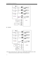
1
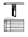
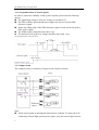
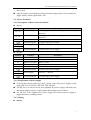
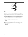
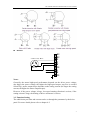
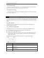
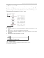
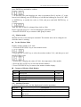
DP-708/DP-5022 Stepper Driver User’s Manual ' Xinje Electronic Co.,Ltd NO. DC012 20100811 1.0 DP-708/DP-5022 series Content 1. Summary........................................................................................................................................................ 1 1-1. Characteristic ..................................................................................................................... 1 1-2. Application......................................................................................................................... 1 1-3. Electric characters .............................................................................................................. 1 2. Operation Guide ............................................................................................................................................. 2 2-1. Safety ................................................................................................................................. 2 2-2. Attention ........................................................................................................................... 2 2-3. Installation ......................................................................................................................... 2 3. Common Terminals......................................................................................................................................... 3 3-1. Control signal terminals ..................................................................................................... 3 3-1-1. Description of Control signal terminals .................................................................. 3 3-1-2. Sequential chart of control signals.......................................................................... 4 3-1-3. Input circuit ............................................................................................................ 4 3-2. Power Terminals ............................................................................................................... 5 3-2-1. Description of Heavy-current terminal ................................................................... 5 3-2-2. Requirement of power supply................................................................................. 5 3-2-3. Wiring ..................................................................................................................... 5 3-3. Function Setting ................................................................................................................. 7 3-3-1. Current Setting........................................................................................................ 8 3-3-2. Subdivision Setting................................................................................................. 8 4. Digital panel ................................................................................................................................................... 8 4-1.Basic operation ................................................................................................................ 8 4-1-1.Functions of digital panel ..................................................................................... 8 4-1-2.Basic state switching ............................................................................................ 9 4-2.Parameter setting ............................................................................................................. 9 4-3.Monitor mode ................................................................................................................ 11 4-4.Auxiliary Function ......................................................................................................... 11 4-4-1.Check System Information ................................................................................. 12 4-4-2.Check Alarm Information ................................................................................... 12 4-4-3.Reset Parameters to Default ............................................................................... 13 4-4-4.External communication monitoring .................................................................. 13 4-4-5.Forced enable...................................................................................................... 13 4-5.Alarm ............................................................................................................................. 13 5. Dimension installation and wiring ................................................................................................................. 15 5-1. Dimension ....................................................................................................................... 15 5-2. Installation ...................................................................................................................... 15 5-3. Typical Wiring ................................................................................................................ 15 6. Malfunction Diagnoses and Solution ............................................................................................................. 17 7. Motor Selection ............................................................................................................................................ 18 i DP-708/DP-5022 series stepper driver ii DP-708/DP-7022series subdivision driver user’s manual 1. Summary DP-708/DP-5022 subdivision stepper driver with 80VDC/220VAC input7.0A /5.0A output current is used for all the 2-phase/3-phase hybrid stepper motor whose rated current is below 7.0A/5.0A. Based on the digital control technology and pure sine wave current control technology, this series product have a good performance in smoothly running with low noise ,meets the high resolution requirement of the numerical control equipments, such as laser marking machine, CNC machine etc. 1-1. Characteristic Strong anti-interference ability and digital control technology Low running noise of motor Power supply reaches 80VDC/220VAC Effective value of current up to 7.0A/5.0A Dynamic select the subdivision, can up to 300 The DP-708 driver can match with all the 4/6/8 wires motors whose current is below 7.0 A Photo isolation signal input Easy to set current, any level selectable Over-voltage and over-current protection 1-2. Application It is suitable for small and medium automation devices and instruments, such as aerodynamic marking machine, labeling machine, cutting machine, laser marking machine, small carving tool, CNC machine etc., especially having a perfect performance for the devices need low noise and vibration, high precision and speed. 1-3. Electric characters Min. value Typical value Max. value DP-708(VDC) 20 80 80 DP-5022(VA) 200 220 240 DP-708 (A) 0 - 7 DP-5022 (A) 0 - 5 Logic current input (mA) 4 7 16 Frequency of stepping pulse (KHz) 0 - 200 Insulation resistance (MΩ) 500 - - Item Power supply Virtual value of current output Environment temperature 0℃~50℃ Max working temperature 70℃ Humidity 40%~90% RH (no condensation) Vibration 5.9m/s2 Max Storage temperature -20℃~65℃ 1 DP-708/DP-5022 series stepper driver 2. Operation Guide Please read the following suggestions carefully before you install the driver. 2-1. Safety The driver is authorized to be installed and operated by the professional staff. Don’t turn on the power before connecting to the motor. Make sure that the input signals meet the technical requirements. Don’t make the setting or measure operations on the motor and driver during power on. Please do the wiring, installation and parameter setting after power is off for more than 3 minutes. Ensure the connection operation is absolutely correct and fixable before you turn on the power, including the power wire, motor cable and signal cable. Avoid electromagnetic interference. 2-2. Attention Please use shield cable for signal input, and leave each other for distance. The further the distance, the better the interference is avoided. Please connect the motor cover to the GND terminal. Don’t operate on the output terminal when power on, or else the driver will be damaged. 2-3. Installation 2 Don’t install the driver next to the heating devices. Don’t exposure the driver to the dusty, corrosive gas, high humidity, and strong vibration environment. For perfect conducting, the ground cable of PC, driver and motor should contact with the ground for large area. DP-708/DP-7022series subdivision driver user’s manual 3. Common Terminals POWER STA|ESC CHARGE INC DEC ENTER CAUTION! A+ AB+ BNC L1 L2 3-1. Control signal terminals 3-1-1. Description of Control signal terminals Signal A B PUL+ PULDIR+ DIR- ENA+ ENAERRO COM Function Description Communication RS485 communication terminal Pulse control The rising edge is effective; motor moves one step at the signal rising edge of pulse. PUL high voltage is 24V, low voltage is 0~0.5V. Direction High voltage 24V and low voltage 0~0.5V correspond to control signal two directions of the motor. Exchanging the signal can change the motor direction. The original direction of the motor depends on the wiring. Exchange any phase wiring can change the motor turning direction. Enable signal To release the motor. When ENA+ connects to 24V, ENAconnects to low voltage, the driver will cut all phase current of the motor, and the stepper pulse will not be responded. Please let the terminal be vacant if out of use. Error signal Output the error signal when the driver is under-voltage output or over-voltage. 3 DP-708/DP-5022 series stepper driver 3-1-2. Sequential chart of control signals In order to ensure the reliability of the system response, please take the following advices. The signal high voltage is 24V; low voltage is less than 0.5V. The ENA (enable) signal should turn to high-level at least 3s before DIR (direction) signal. Ensure the falling edge of the DIR (direction) signal is built at least 5μs before PUL (pulse) signal. The width of pulse should be more than 1.2μs The duration of the pulse low-voltage should be more than 1.2μs The sequential chart is shown as below: 3-1-3. Input circuit The common positive connection of input circuit is shown as below: Note: 4 All the input signals go through the photoelectric isolation. To ensure the well conducting of inside high-speed optical coupler, keep the control signal current DP-708/DP-7022series subdivision driver user’s manual above 8mA. Optical coupler current limiting resistor is built in stepper driver. It is common to supply all the control signals with +24V. 3-2. Power Terminals 3-2-1. Description of Heavy-current terminal DP-708 Terminal A+, AB+, BNC L1 L2 Function Phase A of motor Ground terminal Power supply Description Exchanging A+ and A- can change the motor running direction Exchanging B+ and B- can change the motor running direction Vacant Ground of the power supply 20VDC ~ 80VDC Ground terminal Ground of the power supply Phase B of motor DP-5022 Terminal Function NC Phase U of motor Phase V of motor Phase W of motor Ground terminal Vacant Vacant Phase U input Phase V input Phase W input Ground of the power supply Power supply 200 VAC ~ 240VAC Ground terminal Ground of the power supply NC U V W L N Description 3-2-2. Requirement of power supply To keep the normal working of drive, please ensure the power supply in this range: DP-708: 20~80VDC; DP-5022: 200~240VAC. For DP-708, it is advised to use non-regulated DC power supply, and make sure the current output of power is 60% higher than setting current of driver. For DP-708, if use regulated DC power supply, the current of power supply is higher than motor working current. 3-2-3. Wiring DP-708 5 DP-708/DP-5022 series stepper driver 2-Phase Step Motor 20~80VDC A+ AB+ BNC PE L1 L2 PE Note: The motor performance depends on the connection between driver and motor. Generally, the high-speed performance of motor depends on the power supply voltage (the higher the power voltage, the higher the high-speed torque, can avoid the step missing), and the output torque depends on the setting current (the greater the setting current, the higher the output torque of motor). However, please pay attention that the motor is getting hot when the power voltage is higher, and the vibration is obviously big when the motor is running at a low speed. Above all, please do the connection according to the actual requirements. 6 There are some typical connections for your reference: 8-wire parallel connection mode: the setting current is 1.4 times of rated motor current. 8-wire serial connection mode: the setting current value is 70% of rated motor current. 4/6-wire high-speed mode: the setting current value should be lower than the motor rated current. 6-wire high-torque mode: the setting current value should be 70% of the motor rated current. DP-708/DP-7022series subdivision driver user’s manual DP-5022 3-Phase Step Motor AC200~240V NC NC U V W PE L N PE Notes: Generally, the motor high-speed performance depends on the driver power voltage (the bigger the power voltage, the higher the high-speed torque, step loss is avoided effectively), motor output torque depends on the setting current (the larger the setting current, the higher the motor output torque). However, if the power voltage is large, low-speed running vibration is serious; if the setting current is large, the heating of driver and motor is serious. 3-3. Function Setting The subdivision precision and current can be set through the parameter by the driver panel. For more details please refer to chapter 4-2. 7 DP-708/DP-5022 series stepper driver 3-3-1. Current Setting Set the current in the range of 0~0.7A/5.0A through the parameter P0-00. Set the half-current or full-current mode through the parameter P0-01. 3-3-2. Subdivision Setting The subdivision precision can be set through the parameter P0-02,for more details please refer to chapter 4-2. 4. Digital panel This chapter describes the basic operation of the digital panel. The digital panel can be used to set parameters and run the motor. Operate the digital panel when you read this chapter. 4-1.Basic operation This section provides information on the basic operation of the digital panel for setting operating conditions. 4-1-1.Functions of digital panel The digital panel can be used to set parameters, display the command and state. 5-bit digital tube: display the driver parameter, alarm and status. Power LED: it lights when power on. Charge LED: it lights when the main circuit is powered on. When power is off, electric charges still stays in the capacitor, and at this time DO NOT touch the stepper driver cables. The following will explain the button functions of the original digital panel. Button Name Function STATUS/ESC Press: status switch, status return Press: increase the value, Press and hold: Increase the value continuously. Press: Decrease the value; Press and hold: Decrease the value continuously. Press: Shift; Press and hold: Enter setting and read data mode INC DEC ENTER 8 DP-708/DP-7022series subdivision driver user’s manual 4-1-2.Basic state switching Display the running state, set the parameters and run the command through digital panel state switching. The basic states include running state, monitor state, auxiliary function state, parameter setting state, alarm state (visible when error). The states will change as the following chart after touching the STATUS/ESC button. Display mode: Parameter setting PX-XX: the first X means group No., the last two X means the No. in this group. Monitor mode U-XXX: XXX means the monitor parameter NO. Auxiliary function mode FX-XX: the first X means group No., the last two X means the No. in this group. Alarm mode E-XXX: XXX means the alarm code. Running state: Driver is OFF Driver is in enable off state (panel force enable) Running Driver is in enable on state. 4-2.Parameter setting Select the function via parameter setting, the parameters are shown as below: Modbus address: 0x000~0x005 9 DP-708/DP-5022 series stepper driver Table 1 driver parameters P0- Name Unit 00 Phase-current (virtual value) 0.1A 01 Default setting Setting range Reference 10 0~70 Half-current enable 0 0~1 02 Pulse number per circle 1600 200~65535 03 Modbus station NO. 1 1~255 04 Parameters of serial port 2206 0~2209 Refer to table 2 05 Internal / Selection 0 0~1 0: External Pulses 1: Internal pulses External Pulse Table 2 Function 0: Half-current 1: Full-current Serial port parameters Default Setting Setting Range P0-04.0 Baud Rate 6 0~9 0: 300 1: 600 2: 1200 3: 2400 4: 4800 5: 9600 6: 19200 7: 38400 8: 57600 9: 115200 P0-04.1 Data Bit 0 0: 8 P0-04.2 Stop Bit 2 0: 2 Bit 2: 1Bit P0-04.3 Parity Bit 2 0~2 0: None 1: Odd 2: Even The steps to change the parameters: The parameter setting is used to change the parameters. Check the permitted range of the parameters in the above table before changing the data. This example shows how to change parameter P0-02 from 8 to 16. 1. Press the STATUS/ESC key to enter parameters setting mode and then press the ENTER key to enter. 2. At this time ,the left second LED is blinking ,and press ENTER key to confirm, the right two LEDs are blinking, press INC key, DEC key or ENTER key to select NO. 2 10 DP-708/DP-7022series subdivision driver user’s manual press ENTER key and hold to confirm. 3. At this time, the panel displays the value in parameter P0-02, and the “0” at the lowest bit is blinking, press ENTER key to left shift the blinking bit. Press INC, DEC or ENTER key to modify the value to 3200, and press and hold ENTER key to confirm. Thus, the value in P0-02 is changed from 1600 to 3200. Please repeat the steps 2 to 3 if need changing the parameter again. 4. Press STATUS/ESC key to return to other group or status. 4-3.Monitor mode Monitor the driver state and input command. The monitor state can be changed even when the motor is running. Use the Monitor Mode Display monitor number U-01 state. 1. Press the STATUS/ESC key to enter monitor mode. 2. Press the INC or DEC key to select the monitor number U-01, and then press and hold ENTER to enter. 3. At this time, it displays the value of U-001, the temperature of the module. 4. Press the INC or DEC key to select the monitor number. 5. Press STATUS/ESC key to return to the monitor number display. Contents of Monitor Mode Display Number Monitor Display Unit U-000 Motor speed rpm U-001 Module temperature 0.1° U-002 Bus voltage V U-003 Coil current 0.1A 4-4.Auxiliary Function In auxiliary function state, use the digital panel to do the operations. Group No. Description F0-** Check system information,display system No.and data Check the alarm information,display the alarm code and the status of F1-** the motor F2-00 Return to default value for all the parameters 11 DP-708/DP-5022 series stepper driver F3-00 F4-00 External communication monitoring Forced enable 4-4-1.Check System Information Press the STATUS/ESC key to select the auxiliary function mode. Set the group No. to 0 to check system information. Press INC or DEC key to select different No., and press and hold ENTER key to check current information. Press STATUS/ESC key to return. Information No.: Code Description F0-00 Driver Serial No. F0-02 Date: Year F0-04 Date: Day F0-06 Hardware Version Code Description F0-01 Type F0-03 Date: Month Software Version F0-05 4-4-2.Check Alarm Information Set group No. to 1 in auxiliary function and enter alarm information state. The following steps show how to check alarm information. 1. Press STATUS/ESC key to select Auxiliary Function. 2. Press INC or DEC key to set group No. to 1, and press ENTER key. 3. Press INC, DEC or ENTER key to modify the No. 4. Press ENTER key, display corresponding alarm information. Code Description Current alarm code ※1 Current warn code ※2 Alarm/warn code 1 when alarm U phase current when alarm V phase current when alarm Effective current values when alarm Bus voltage when alarm Module temperature when alarm Motor speed when alarm Alarm/warn code 2 when alarm Alarm/warn code 3 when alarm Alarm/warn code 4 when alarm Alarm/warn code 5 when alarm Alarm/warn code 6 when alarm Alarm/warn code 7 when alarm ※1: When F1-00=0,indicates that there is no alarm. ※2: When F1-01=0,indicates that there is no warn. F1-00 F1-01 F1-02 F1-03 F1-04 F1-05 F1-06 F1-07 F1-08 F1-09 F1-10 F1-11 F1-12 F1-13 F1-14 12 Unit A A A V ℃ rpm Modbus address 0x0305 0x0306 0x0307 0x0308 0x0309 0x030A 0x030B 0x030C 0x030D 0x030E 0x030F 0x0310 0x0311 0x0312 0x0313 DP-708/DP-7022series subdivision driver user’s manual 4-4-3.Reset Parameters to Default The following steps show how to reset parameters to default values. 1. Press STATUS/ESC key to select Auxiliary Function. 2. Press INC or DEC key to set group No. to 2, and press ENTER key to confirm. 3. Press and hold ENTER key and 0 is blinking on the digital panel. 4. Set the value to 1. Press and hold ENTER key to confirm. 5. Restart the driver and the parameters are all reset to default values. 4-4-4.External communication monitoring Select F3-00 in auxiliary mode, it displays C-OUT which means external monitor state, serial port 1 (COM1) is available, panel monitor is unavailable. You can debug the driver via PC. Press STATUS/ESC to return and quit C-OUT. 4-4-5.Forced enable Select F4-00 in auxiliary function, then press ENTER and hold to enter the parameter setting status. Press INC and DEC to modify the parameter, press ENTER key and hold to confirm. 0: Cancel forced enable 1: forced enable 4-5.Alarm The driver will show alarm state when there is error; the alarm state is invisible if no error. E-XXX means system error. EEEEE means digital panel communication error. Press ENTER to reset part of the alarm information. Please note that clear the error then clear the alarm. Alarm information is shown as below: Alarm Description Causes code E-001 Program Damage Program self-test failure E-002 Parameter Damaged Parameter self-test failure Bus over-voltage Bus under voltage Module temperature is too high Power voltage is too high Power voltage is too low Driver is working under big current for long time; Ambient E-003 E-004 E-005 Solution Re-download the program or contact Xinje or an authorized distributor Restart the driver to reset the parameters to default values. If it happens for many times contact Xinje or an authorized distributor Note ● ● Check the power voltage △ Check the power voltage △ Reduce the current, and enhance the cooling system, or check if the fan is working; decrease the △ 13 DP-708/DP-5022 series stepper driver E-006 Over Current E-007 System initialize failure temperature is higher than normal. Driver output to motor error or motor error ambient temperature. Change the damaged motor and check motor wiring ● System IC is damaged. Contact Xinje or an authorized distributor. ● ● Can not clear the alarm information through digital panel, need re-power. △ Can clear the alarm information through digital panel after remove the error, no need to re-power. Warning information is shown as below: Warning code Description 1 Bus voltage is too high Bus voltage is too low Module temperature is too high Temperature detection is abnormal Bus voltage detection is abnormal 2 3 4 5 14 Note DP-708/DP-7022series subdivision driver user’s manual 5. Dimension installation and wiring 5-1. Dimension Unit: mm 5-2. Installation Install the driver in the well-ventilated and protected electric cabinet, check the fan regularly. To ensure the driver heat dissipation is well, keep at least 10cm space when installing. To avoid dust and scrap fall into the driver. 5-3. Typical Wiring DP-708 15 DP-708/DP-5022 series stepper driver DP-5022 Note: please separate the power cables (power supply cable and motor phase cable) and the weak electricity cable in order to avoid interference. 16 DP-708/DP-7022series subdivision driver user’s manual 6. Malfunction Diagnoses and Solution Malfunction The power light doesn’t work The motor doesn’t work The direction of motor is incorrect Causation Solution Something wrong with the power supply Check the power supply The power voltage is too low Increase the power voltage Setting current is too low Reset the current Subdivision is too small Reset the Subdivision Protection circuit is working Re-power the driver The release signal is low Do not connect the signal Power off Re-power Motor wiring is error Check the wiring No pulse input Adjust the pulse width and signal voltage Inverse of phase-sequence Exchange the phase-sequence Disconnection Motor wiring is wrong Alarm indicator lights Motor torque is too small Check the wiring Re-wiring The voltage is too low or high Adjust the power voltage Motor or drive is damaged Check the driver and motor Acceleration is too high Reduce the acceleration value Driver doesn’t match with the motor Change the driver 17 DP-708/DP-5022 series stepper driver 7. Motor Selection The DP-708 series driver matches with 4/6/8 wires 2-phase hybrid stepper motor. Please select the suitable motor and driver. The DP-5022 series driver matches with 3/6 wires 3-phase hybrid stepper motor. Please select the suitable motor and driver. Please pay attention to the torque and rated current when choosing a motor. The torque depends on the motor dimension, the bigger the dimension, and the greater the torque. And the current depends on the resistor, the smaller the resistor, the greater the current, and the motor will have good performance at high speed. But for certain connection motor, the bigger the working current, the greater the torque, the motor heating is serious; the higher the driver power voltage, the bigger the motor high-speed torque. The high-speed torque of motor is smaller than low-speed torque. 18 Xinje Electronic Co., Ltd. 4th Floor Building 7,Originality Industry park, Liyuan Development Zone, Wuxi City, Jiangsu Province 214072 www.xinje.com Tel: (510) 85166657 Fax: (510) 85111290