1
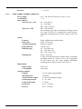
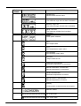
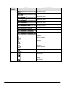
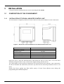
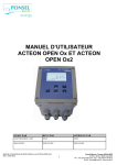
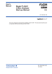
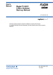
DISSOLVED OXYGEN AND TEMPERATURE ANALYSER 0000137234 Rev. 1.0 INDEX 1 GENERAL INFORMATION................................................................................................................................. 6 1.1 INFORMATION REGARDING THE MANUAL ............................................................................................ 6 1.1.1 CONVENTIONS ........................................................................................................................................ 6 1.2 LIMITATIONS OF USE AND SAFETY PRECAUTIONS.............................................................................. 6 1.2.1 ELECTRICAL SAFETY ............................................................................................................................. 6 1.2.2 SAFETY OF THE OPERATING ENVIRONMENT ................................................................................... 7 1.3 GRAPHIC SYMBOLS ............................................................................................................................................. 8 1.4 ATTENTION SYMBOL ...................................................................................................................................... 8 1.5 DATA PLATE DETAILS ........................................................................................................................................ 9 1.6 INFORMATION REGARDING THE RECYCLING AND REUSE OF THE MATERIALS .................................................. 9 1.6.1 SPECIAL REQUIREMENTS FOR CRITICAL COMPONENTS ............................................................... 9 2 GENERAL DESCRIPTION................................................................................................................................... 9 2.1 MEASUREMENT PRINCIPLES.................................................................................................................... 10 2.2 MAIN CHARACTERISTICS ................................................................................................................................ 11 2.2.1 DISSOLVED OXYGEN measurement technical characteristics............................................................. 11 2.2.2 Temperature measurement technical characteristics (secondary) ......................................................... 11 2.2.3 Functional characteristics....................................................................................................................... 12 2.3 CONTROLS, INDICATORS AND CONNECTIONS .................................................................................... 13 2.4 GRAPHIC DISPLAY ............................................................................................................................................ 14 2.4.1 List of the main menus............................................................................................................................. 14 2.4.2 Division of the graphic display BY ZONES in run mode ........................................................................ 15 3 INSTALLATION................................................................................................................................................... 18 3.1 COMPOSITION OF THE CONSIGNMENT .............................................................................................................. 18 3.1.1 Installation of the Wall-mounted control unit ......................................................................................... 18 3.1.2 Connection to the Power Supply ............................................................................................................. 19 3.1.2.1 Electrical connections to the dosing systems (Utilities)...................................................................... 19 3.1.2.1.1 Terminal board for the wall-mounted device 4283....................................................................... 20 3.1.2.2 Connections To The Electrical Network ............................................................................................. 21 3.1.3 ConnectiNG the ELECTRODE TO the ANALYSER................................................................................ 21 4 METHODS OF USE ............................................................................................................................................. 22 4.1 COMPOSITION OF THE MEASUREMENT SYSTEM ............................................................................................... 22 4.1.1 MINIMUM CONFIGURATION .............................................................................................................. 22 4.1.2 MAXIMUM CONFIGURATION ............................................................................................................. 22 ACTIVATING THE SYSTEM ............................................................................................................................................ 23 4.1.3 MENU FUNCTIONS UPON ACTIVATION............................................................................................ 23 4.1.3.1 Contrast adjustment ............................................................................................................................. 23 4.2 INTRODUCTION TO THE OPERATING PARAMETERS........................................................................................... 23 4.2.1 SETTINGS MENU (temperature – system setup).................................................................................... 24 4.2.2 SETTINGS MENU (DIGITAL INPUT – CONDUCTIVITY) ................................................................... 26 4.2.3 SETTINGS MENU (PROCESS PRESSURE – UNIT OF MEASURE) .................................................... 26 4.2.4 OUTPUTS MENU (relay outputs – SET POINT 1)................................................................................. 27 4.2.5 OUTPUTS MENU (relay outputs – SET POINT 2, ETC.) ...................................................................... 30 4.2.6 OUTPUTS MENU (TEMP. SET POINT) ................................................................................................ 32 4.2.7 OUTPUTS MENU (analogUE output) .................................................................................................... 33 4.2.8 OUTPUTS MENU (PID SETUP) ............................................................................................................ 34 4.2.9 CALIBRATION MENU............................................................................................................................ 35 4.2.10 ARCHIVES MENU .................................................................................................................................. 38 4.2.11 MEASUREMENT GRAPHICS MENU .................................................................................................... 39 4.2.12 MANUAL CONTROL MENU .................................................................................................................. 40 0000137234 Rev. 1.0 4.2.13 5 USER MAINTENANCE ....................................................................................................................................... 43 5.1 6 Functions in run mode............................................................................................................................. 41 SPECIAL REQUIREMENTS FOR CRITICAL COMPONENTS .................................................................. 43 APPENDIX: TABLES OF OXYGEN SOLUBILITY AND CONVERSION/CORRECTION FACTORS . 44 0000137234 Rev. 1.0 1 1.1 GENERAL INFORMATION INFORMATION REGARDING THE MANUAL In order to guarantee the device’s proper functionality and operator safety, it is fundamental that the operative procedures and precautions described in this manual be respected. Before using the device, the manual must be read in all of its parts, in the presence of the device itself, in order to ensure that the operating modes, the controls, the connections to the peripheral equipment and the precautions for safe and correct use are clearly understood. The user manual must be stored, integral and legible in all parts, in a safe place which can be quickly and easily accessed by the operator during installation, use and/or installation revision operations. 1.1.1 CONVENTIONS This user manual makes use of the following conventions: NOTE The notes contain important information to be highlighted with respect to the rest of the text. They generally contain information that is useful to the operator for properly performing and optimising the device’s operating procedures. CAUTION Caution messages appear in the manual before procedures or operations that must be observed in order to avoid any possible loss of data or damage to the equipment. ATTENTION Attention messages appear in the manual wherever procedures or operations are described which , if carried out incorrectly, could cause injury to the device’s operator or users. 1.2 LIMITATIONS OF USE AND SAFETY PRECAUTIONS In order to guarantee operator safety and correct device functionality, all of the usage limitations and precautions listed below must be respected: ATTENTION Make sure that all the safety requirements have been met before using the device. The device must not be powered on or connected to other devices until all of the safety conditions have been met. 1.2.1 ELECTRICAL SAFETY ATTENTION All of the control unit’s connections are isolated from the grounding system (non-insulated grounding conductor). DO NOT connect any of these connections to the grounding connector. 0000137234 Rev. 1.0 6 In order to guarantee maximum conditions of safety for the operator, it is recommended to follow all of the indications listed in this manual. Only power the device using a mains power supply that complies with the device’s specifications (85÷265Vac 50/60Hz) Replace any damaged parts immediately. Any cables, connectors, accessories or other parts of the device which are damaged or not functioning properly must be replaced immediately. In such cases, contact your nearest authorized technical assistance centre. Only use accessories and peripherals specified by the supplier. In order to guarantee all of the safety requirements, the device must only be utilized in conjunction with the accessories specified in this manual, which have been tested for use with the device itself. The use of accessories and consumables produced by other manufacturers or not specifically indicated by the device’s provider will not guarantee the its safety and proper functionality. Only use peripherals that comply with the regulations of their specific categories. 1.2.2 SAFETY OF THE OPERATING ENVIRONMENT The control unit’s panel is resistant to liquids. The device must be protected against drips, sprays and/or immersion and should not be used in environments where such risks are present. Any devices into which liquids may have accidentally penetrated must be immediately shut off, cleaned and inspected by authorised and qualified personnel. The transparent panel should be closed once the device has been programmed. Protection For ACP 4283 Wall mounting IP66 EN60529 EMI /RFI CEI EN55011 - 05/99 The device must be utilized within the specified environmental temperature, humidity and pressure limits. The instrument is designed to operate under the following environmental conditions: Temperature of the working environment 0°C ÷ +50°C Storage and transport temperature -25°C ÷ +65°C Relative humidity 10% ~ 95% RH (without condensation) ATTENTION The device must be perfectly inserted into the system. The system must be maintained operational in full compliance with the foreseen safety regulations. The parameters set on the analyser’s control unit must comply with the current regulations. The control unit’s malfunction signals must be located in an area that is constantly supervised by the system’s maintenance personnel or operators. Failure to respect even just one of these conditions could cause the control unit’s “logic” to operate in a potentially dangerous manner for the users of the service. In order to avoid any potentially dangerous situations, therefore, the system’s service and/or maintenance personnel are advised to work with the utmost care and to signal any alterations in the safety parameters in a timely fashion. As the above issues cannot be monitored by the product in question, the manufacturer shall bear no responsibility for any property damage or personal injury which may result from such malfunctions. 0000137234 Rev. 1.0 7 1.3 GRAPHIC SYMBOLS The following table illustrates the graphics, the descriptions and the positions of all the graphic symbols present upon the device’s panels, as well as upon any other equipment or external devices to which it may be connected. SYMBOL DESCRIPTION POSITION This symbol is located near the terminals for the device’s connection to the mains power supply. Attention symbol Phase These symbols are located near the device’s mains power supply connector Neutral Grounding wire Attention! Refer to the attached This symbol is located near points for which the user Manual should be consulted for important documentation information. (see the section entitled ATTENTION). 1.4 Positive POSITIVE pole of the RS485 connector (A+) Negative NEGATIVE pole of the RS485 connector (B-) Oxygen electrode Oxygen Electrode Connector NTC Temperature sensor connector Analogue output no.1 0/4 ÷20mA galvanically separated Analogue output no.2 0/4 ÷20mA galvanically separated Recycling symbol This symbol is located on the right hand side of the control unit ATTENTION SYMBOL The ATTENTION symbol, shown below, advises the operator to refer to the user’s Manual for particularly important information, warnings and suggestions regarding the safe and proper use of the device. In particular, when positioned near the connection points for cables and peripherals, this symbol advises the reader to carefully read the user manual for indications regarding the nature of these cables and peripherals and the methods for correctly and safely connecting them. 0000137234 Rev. 1.0 8 In order to determine the locations of the ATTENTION symbols on the device, refer to chapter 2 “Controls and Indicators, Connections” and chapter 3 “Installation” of this user manual. These chapters provide illustrations of the device’s panels, with their relative controls, connections, symbols and labels. Each attention symbol is accompanied by a detailed explanation of its meaning. 1.5 DATA PLATE DETAILS Mod. SN. XXXXXXX Volt 100-240 Vac/dc SW Ver. X.X 1.6 Hz 50/60 INFORMATION REGARDING THE RECYCLING AND REUSE OF THE MATERIALS In compliance with the specific European directives, and in order to minimize the negative environmental impact of the device’s components, consumables and packaging, as well as the device itself at the end of its working life, the manufacturer is constantly working to improve the design and production procedures for its products. The packaging is designed and manufactured to allow for the majority of the materials to be recovered, reused and/or recycled, as well as to minimize the amounts of waste and/or residues to be disposed of. In order to ensure minimal environmental impact, the device has been designed using the maximum possible circuit miniaturisation, with the smallest possible amount of material and component differentiation, with select materials that guarantee maximum recyclability, with maximum parts re-use and with disposal procedures free of environmental risks. The device is manufactured in such a way so as to guarantee that any materials containing pollutant substances can be easily separated or disassembled from the others, particularly during maintenance and part replacement operations. ATTENTION The disposal/recycling of the packaging materials, the consumables and the device itself at the end of its working life must be carried out in compliance with the current regulations and directives of the country in which the device is utilised. 1.6.1 2 SPECIAL REQUIREMENTS FOR CRITICAL COMPONENTS The device is equipped with a liquid crystal display (LCD), which contains small amounts of toxic materials. GENERAL DESCRIPTION The analyser described in this manual is comprised of an Electronic Control Unit and a Technical Manual The control unit may be installed upon the electrical panel or else wall-mounted at a maximum distance of 15 metres from the sensor. 0000137234 Rev. 1.0 9 It is powered by the mains electrical system (100 ÷ 240 Vac/dc 50-60 Hz), with L7W consumption, through a switching Power Supply This device has been designed for the ON-LINE analysis of the dissolved oxygen conditions in various applications: Biological oxidation systems Industrial wastewater drainage and treatment Fish farming Primary or drinking water systems Figure 1 - Wall-mounted temperature and dissolved oxygen analyser control unit 2.1 MEASUREMENT PRINCIPLES Nearly every liquid contains dissolved oxygen, in greater or lesser quantities. Tap water, for example, contains a about 9 mg/L of oxygen at a temperature of 20° C and at an atmospheric pressure of 1013 mbar. Ethanol can reach a concentration of 40 mg/L while glycerine can reach a concentration or merely 2 mg/L. Every liquid absorbs the amount of oxygen required to balance the partial pressure of the oxygen in solution with that of the air or the gaseous substance with which it is in contact. Oxygen concentration is also subordinate to a number of factors, such as temperature, atmospheric pressure, reduction processes due to microbiological activities or additive processes due to, for example, algae growth. Oxygen concentration is fundamental for various factors, including: For maintaining life sustaining conditions for the fish and microorganisms present in the water; Degradation processes for water purification; Corrosion processes in pipelines; The shelf life of beverages. In the past, the percentage of oxygen was determined using the WINKLER titration method. Today, the procedure recognised by various standards is electrochemical oximetry. In its most simple design, an oxygen sensor contains a working electrode and a counter electrode. Both electrodes are equipped with an electrolytic system separated from the solution to be analysed by means of a gas-permeable membrane. 0000137234 Rev. 1.0 10 The working electrode reduces the oxygen molecules to form hydroxyl ions. The more oxygen is present within the solution, the greater the generated electrical signal will be. With the help of a solubility function, the oximeter uses this signal to calculate the concentration of oxygen within the solution. 2.2 MAIN CHARACTERISTICS Oxygen measurement Temperature measurement with a NTC/PT100/PT1000 Sensor Automatic Temperature Compensation Programming keyboard with 5 embossed keys 128x68 Back-lit LCD Graphic Display Internal Data Logger (4 Mbit flash) with graphical and tabular measurement trend display PID Adjustment RS485 MOD BUS RTU Serial Output Data download to USB pendrive (optional) 2 Programmable Analogue Outputs 2 Relay Outputs for intervention thresholds 1 Relay Output for Instrument Malfunction Alarm or Temperature Set Point 1 Relay Output for Sensor Washing or Temperature Set Point 1 Digital Input for dosage disabling Main control unit hardware characteristics The hardware structure of this device is based on the use of state of the art 8-bit CMOS CPUs, which are designed specifically for so called “embedded” applications. The board uses flash memories to store the historical data archives as well as the event LOG files. The board is equipped with an RS485 serial port (opto-isolated) for local networks, which can be used to connect to local communications devices (Configuration Computers, Remote Terminals, etc.). The board also has an integrated Real Time Clock (calendar clock) which allows the software to store the data in chronological order. The control unit is manufactured with an IP66-rated panel. 2.2.1 DISSOLVED OXYGEN MEASUREMENT TECHNICAL CHARACTERISTICS The analyser’s technical characteristics are listed below: Ranges of measurement Resolution Precision 2.2.2 0.00 ÷ 20.0 ppm O2 0.00 ÷ 20.0 mg/L 000 ÷ 200 % SAT O2 ± 0.1 ppm O2 ± 0.1 mg/L ± 001 % SAT O2 ± 0.5% F.S. TEMPERATURE MEASUREMENT TECHNICAL CHARACTERISTICS (SECONDARY) Sensor NTC 22 KOhm @ 25°C/PT100/PT1000 Range of measurement -10 ÷ +130°C. Resolution ± 0.1°C 0000137234 Rev. 1.0 11 Precision 2.2.3 FUNCTIONAL CHARACTERISTICS Power supply Consumption Relay outputs: Set Point ON – OFF Time ON – OFF Alarm: Function Delay time Threshold disabling Relay function Holding range Holding time ± 1% F.S: 100 ÷ 240 Vac/dc 50-60 Hz (optional 24 Vac/dc) < 7W 0.0 ÷ 20.0 ppm O2 0.0 ÷ 20.0 mg/L 000 ÷ 200 % SAT O2 000 ÷ 999 Seconds An exchange relay with a maximum switching current of 1 Amp at 230 VAC is employed for each set-point. Maximum switching power with a resistive load: 230 VA. Delay, Malfunctions and Min/Max 00:00 ÷ 99:99 min Enabled / Disabled Closed / Open 0.0 ÷ 20.0 ppm O2 0.0 ÷ 20.0 mg/L O2 000 ÷ 200 % SAT O2 00:00÷ 99:99 min A relay with normally open contacts with a maximum switching current of 1 Amp at 230 VAC is employed for the alarm and the wash outputs. Maximum switching power with a resistive load: 230 VA. Digital input: Input voltage Consumption Analogue outputs: Outputs Maximum load NAMUR alarm output PID dosing function Proportional band Integration Derived 0000137234 24 Vdc /ac 10mA max n.2 0/4-20mA Programmable 500 Ohm 2.4 mA (with Range 4/20mA) P – PI – PID 0 – 500% 0:00 – 5:00 min 0:00 – 5:00 min Rev. 1.0 12 2.3 CONTROLS, INDICATORS AND CONNECTIONS 1 3 2 5 6 4 Figure 2 – Wall-mounted control unit, Front panel 1. 2. 3. 4. 5. 6. LCD Display UP Key ESC Key ENTER Key DOWN Key GRAPH Key Figure 3 – Access to the terminal board 0000137234 Rev. 1.0 13 2.4 GRAPHIC DISPLAY The graphic display offers access to the various menus, as well as to the programming and operating (run) display modes. 2.4.1 LIST OF THE MAIN MENUS The following table illustrates the various menus available on the display. DISPLAY ICON DESCRIPTION SETTINGS MENU Allows for the configuration of all the device’s basic functioning parameters OUTPUTS MENU Analogue and digital output settings CALIBRATION MENU Electrode Calibration Procedure ARCHIVES MENU Data display and archiving mode settings MEASUREMENT GRAPHICS MENU Archive display in graphic format MANUAL CONTROL MENU Manual activation and control of the inputs and outputs 0000137234 Rev. 1.0 14 2.4.2 DIVISION OF THE GRAPHIC DISPLAY BY ZONES IN RUN MODE Figure 1 – Graphic display – Zone division The following table provides a brief description of the various symbols that can appear in each zone of the graphic display (indicated in figure 3) while the measurement control unit is in function. GRAPHIC ZONE SYMBOL DESCRIPTION 1 Set1 - Relay Open Set1 - Relay Closed Set1 – Programmed, Timed, Threshold Enabled, Relay Open Set1 – Programmed, Timed, Threshold Disabled, Relay Open Set1 – Programmed, Timed, Threshold Enabled, Relay Closed 2 Set2 - Relay Open Set2 - Relay Closed Set2 – Programmed, Timed, Threshold Enabled, Relay Open Set2 – Programmed, Timed, Threshold Disabled, Relay Open Set2 – Programmed, Timed, Threshold Enabled, Relay Closed 1-2 0000137234 Set Disabled Indicates digital input ON Rev. 1.0 15 GRAPHIC ZONE SYMBOL DESCRIPTION Holding time Sensor frozen on one value Max Logic Set The maximum logic set has been exceeded Min.bmp Logic Set The minimum logic set has been exceeded Relay Time Out The maximum dosage time has been exceeded 3 Wash Wash phase enabled 4 mA1 mA1 output value mA2 mA2 temperature output value mA2 auxiliary mA2 auxiliary output value mA2 PID Output value as PID Fahrenheit thermometer Automatic temperature in Fahrenheit Manual Fahrenheit Thermometer Manual temperature in Fahrenheit Celsius thermometer Automatic temperature in Celsius Manual Celsius Thermometer Manual temperature in Celsius 5 Waiting Freeze phase, measurements and outputs 6 Numeric values 7 0% of the scale 10% of the scale 0000137234 Rev. 1.0 16 GRAPHIC ZONE SYMBOL DESCRIPTION 20% of the scale 30% of the scale 40% of the scale 50% of the scale 60% of the scale 70% of the scale 80% of the scale 90% of the scale 100% of the scale 8 Oxygen Unit of measure Oxygen Unit of measure Oxygen Unit of measure Seconds during stabilisation 9 Archive full Saving Data saved 0000137234 Rev. 1.0 17 3 INSTALLATION Carefully read the information below before installing the ACP 4283. 3.1 COMPOSITION OF THE CONSIGNMENT 3.1.1 INSTALLATION OF THE WALL-MOUNTED CONTROL UNIT The wall must be completely smooth in order to allow for the perfect adhesion of the control unit. Figure 5 – Dimensions and encumbrance of the wall-mounted control unit Mechanical Dimensions ACP 4283 144x144x122.5mm Dimensions (L x H x D) 122.5mm ABS Grey RAL 7045 Wall 1 Kg Installation depth Material Installation typology Weight Front Panel UV resistant polycarbonate Open the device, drill the indicated holes and fasten the device to the wall. Cover the holes internally using the relative caps, which come supplied along with the device. The cable glands for the electrical connections are located on the lower portion of the control unit. In order to facilitate the connections, therefore, any other devices must be positioned at least 15 cm away. Protect the device against any drips and/or sprays of water from adjacent areas during the programming and calibration phases. 0000137234 Rev. 1.0 18 3.1.2 CONNECTION TO THE POWER SUPPLY If possible, keep any high power cables away from the control unit and its connection cable, as these could cause inductive disturbances, especially for the analogical portion of the system. Use an alternating 100Vac to 240Vac-50/60Hz power supply, based on that which is indicated on the device’s data label. The power supply must be as stabilised as possible. Absolutely avoid connecting the device to rebuilt power supplies, using transformers for example, where the same power supply is also used to power other systems (perhaps of an inductive typology). This could lead to the generation of high voltage spikes which, once emitted, are difficult to block and/or eliminate. ATTENTION The electrical line must be equipped with an appropriate circuit breaker, in compliance with the proper installation standards It is nevertheless always a good idea to check the quality of the grounding connector. In industrial facilities, it is not uncommon to find grounding connectors that cause electrical disturbances instead of preventing them; wherever doubts should arise regarding the quality of the facility’s grounding connectors, it is best to connect the control unit’s electrical system to a dedicated grounding rod. 3.1.2.1 Electrical connections to the dosing systems (Utilities) ATTENTION Before connecting the analyser’s control unit to the external utilities, make sure that the electrical panel is off and that the wires from the mains power supplies are not live. The term “utilities” is intended to indicate the relay outputs used in the control unit (SET1) for controlling dosing or control pumps (SET2) for controlling dosing or control pumps (ALARM) alarm command transmitted by the instrument to the siren and/or flashing light (WASH) wash electrode command CAUTION With a resistive load, each relay contact can sustain a maximum current of 1 amp, at max. 230V, and therefore a total power of 230 VA. In the case of higher power values, it is recommended to perform the utility connections based on the scheme provided in fig. 6-b) If, on the other hand, the load is of a low power or resistive typology, the connection scheme in fig. 6-a) can be used 0000137234 Rev. 1.0 19 Loads below 230 VA Loads above 230 VA Remote relay switch Power supply Power supply SET 1 Contact Utilities Utilities SET 1 Contact Figure 6 Examples of connections with the utilities NOTE The schemes shown above are indicative and do not contain the details regarding all of the necessary safety and protection devices. 3.1.2.1.1 Terminal board for the wall-mounted device 4283 Connections with the polarographic sensor S 423 (OXYSENS) Figure 2 Connections for the wall-mounted model TERMINAL NO. 1 2 3 5 6 7 8 9 10 11 12 13 14 0000137234 SYMBOL L N DESCRIPTION Power supply (Ground) Power supply (Phase) Power supply (Neutral) Power supply Sensor (+12V) Power supply Sensor (-12V) Digital input (-) Digital input (+) RS485 (A+) RS485 (B-) Wash and Temp. Relay (N.C. contact) Wash and Temp. Relay (N.O. contact) Alarm and Temp. Relay (N.C. contact) Alarm and Temp. Relay (N.O. contact) Rev. 1.0 20 TERMINAL NO. SYMBOL 19 20 21 22 30 31 32 33 34 35 36 37 38 39 DESCRIPTION Set Point 2 Relay (N.C. contact) Set Point 2 Relay (N.O. contact) Set Point 1 Relay (N.C. contact) Set Point 1 Relay (N.O. contact) mA2 Output (-) mA2 Output (+) mA1 Output (-) mA1 Output (+) Common NTC / PT100 / PT1000 Cable Signal NTC / PT100 / PT1000 Cable Signal NTC / PT100 / PT1000 Cable Common NTC / PT100 / PT1000 Cable Oxy Probe (+) Marrone/Brown Oxy Probe (-) Trasparente/Transparent Connections with the optical sensor S 423 /N/OPT Only the connections which vary with respect to those indicated in figure 7 are listed below: TERMINAL NO. 5 6 25 26 SYMBOL DESCRIPTION Red Sensor Cable S423/N/OPT Black Sensor Cable S423/N/OPT White Sensor Cable S423/N/OPT Green Cable S423/N/OPT 3.1.2.2 Connections To The Electrical Network After having verified that the mains voltage complies with the requirements set forth in the previous sections, connect the electrical cable to the indicated terminals and the ground wire to the terminal bearing the appropriate symbol. 3.1.3 CONNECTING THE ELECTRODE TO THE ANALYSER Shut off the device. Connect the electrode’s cables (S423 OXYSENS or S423/N/OPT ) to the terminals of the analyser’s terminal board. Follow the colour-scheme illustrated on the label beneath the cover of the electrical compartment, or consult the manual (see 3.1.3.1.1 and 3.1.3.1.2). Both measurement sensors come with 5-metre long cables. For connections over greater distances, observe the following indications: for the S423 OXYSENS, do not exceed a cable length of 25 metres. for the S423//N/OPT, do not exceed a cable length of 1000 metres. It is also recommended to avoid positioning this cable near high-power cables or inverters in order to prevent Oxygen measurement disturbances. 0000137234 Rev. 1.0 21 4 4.1 4.1.1 METHODS OF USE COMPOSITION OF THE MEASUREMENT SYSTEM MINIMUM CONFIGURATION Figure 3 Minimum configuration 4.1.2 MAXIMUM CONFIGURATION Figure 4 Maximum configuration 0000137234 Rev. 1.0 22 ACTIVATING THE SYSTEM Once the electronic control unit and the measurement sensor have been installed, the software must be programmed in order to “customize” the parameters for the correct use of the equipment. Turn on the device by activating its electrical power supply – the control unit is not equipped with a power switch. 4.1.3 MENU FUNCTIONS UPON ACTIVATION Upon activating the device, certain keys can be used to access programming functions which are not present during SETUP. (See sec. 4.2.1.1; 4.2.1.2; 4.2.1.3) 4.1.3.1 Contrast adjustment Press and hold down the DOWN key while turning on the device. Keep the key pressed until the message “Contrast control” appears on the display. This will access the display’s contrast adjustment screen. NOTE During this operation, release the DOWN button immediately once the first acoustic beep is heard. Otherwise, the display’s contrast value will be brought to 0% and the screen will appear completely white. In order to restore the correct contrast level, press the UP key. Use the UP and DOWN keys to adjust the contrast percentage. 220V DOWN Contrast Control 88 OXY 4283 Ver 1.0 WAIT… ENTER 9.8 O2 20.5 Figure 10 – Contrast Function Flow-Chart When finished, press ENTER to activate the RUN mode view. 4.2 INTRODUCTION TO THE OPERATING PARAMETERS In order to insert/modify the operating data and to perform the calibration procedures, use the 5 function keys on the control unit’s front panel to select the desired menu on the display. When turned on, the device automatically goes into measurement mode – RUN function. Press the ESC key to enter the programming mode. Next, press ENTER to access the various menus. In this manner, all of the outputs will be disabled. Use the UP and DOWN keys to scroll through the various menus and submenus and to modify the data (increase/decrease). Use the ENTER key to access the data insertion submenus and to confirm any modifications. Use the ESC key to return to the previous menu or function without saving any changes. 0000137234 Rev. 1.0 23 4.2.1 SETTINGS MENU (TEMPERATURE – SYSTEM SETUP) ENTER + DOWN (A2) (A1) 1. 0 SETTINGS Temperature System Setup Digital Input Conductivity Process pressure Unit of measure DOWN UP AUT +025°C °C ENTER System Date/Time DATE/TIME UP/DOWN Communication Language Password Display Serial number DOWN ENTER Day Month Year Time Minute 09 03 2010 12 42 1.220 COMMUNICATION AUT +025°C °C Instrument ID Baud rate 1.20 SYSTEM SETUP System Date/Time UP/DOWN Communication Language Password Display Serial number System Date/Time Communication Language Password Display 1.220 SYSTEM SETUP ENTER 1.10 TEMPERATURE Comp.Temp. Manual Temp. Unit of measure 1.20 SYSTEM SETUP ENTER ENTER ENTER 1.10 TEMPERATURE Comp. Temp. Manual Temp. Unit of measure 1. 0 SETTINGS Temperature System Setup Digital Input Conductivity Process pressure Unit of measure 01 9600 1.23 SYSTEM SETUP ENTER 1.241 PASSWORD Language Password Status Password: 0 English UP/DOWN 1.20 SYSTEM SETUP UP/DOWN System Date/Time Communication Language Password Display Serial number ENTER 1.240 PASSWORD Password Status New Password UP/DOWN ENTER 1.20 SYSTEM SETUP System Date/Time Communication Language Password Display Serial number ENTER 1.240 PASSWORD Password status New Password 1.250 DISPLAY ENTER Contrast Backlighting 1.242 PASSWORD 88 NO New Password Password: 0 UP/DOWN 1.20 SYSTEM SETUP System Date/Time Communication Language Password Display Serial number 0000137234 1.26 SYSTEM SETUP ENTER Serial number 12345 Rev. 1.0 24 A1) Temperature The Unit of Measure function allows the user to select whether to display the temperature in Celsius or Fahrenheit. By default, temperature values are displayed in Celsius. A2) System Setup This programming step is divided into 5 functions which can be used to set the instrument’s basic functioning parameters. Function descriptions: SYSTEM DATE/TIME The system’s DATE and TIME setting, which will be used for data archiving. COMMUNICATION The instrument is equipped with a galvanically-separated RS485 serial port, which can be used for communicating with a HOST system over a standard MOD BUS RTU protocol. The serial port can be used to view the system’s real time status, program all of the setup parameters and download the device’s entire archive. The Communication Setup function contains two settings which can be used to program the serial port: Instrument ID: The numeric address from 1 to 99 to which the instrument will respond. The default value is 01. Baud Rate: The speed of the RS485 serial port, which can be programmed from 1200 to 38400. The default value is 9600. LANGUAGE This function allows for the software’s interface language to be selected from amongst: Italian, English, French, Spanish and German. PASSWORD This function allows for a device access password to be enabled and programmed. Once enabled, the access password will be requested every time the user attempts to access the programming mode. The password is made up of a 4-digit number. The default password is 2002. This password will always remain valid even if a new password is programmed. The existing password is required to access the “Password Status” or “New Password” screens before inserting a new password. DISPLAY Contrast: This function allows for the display’s contrast to be increased or decreased based on the temperature in which the instrument is operating. Backlighting: This function allows the user to decide whether the display’s backlighting should always remain on or should automatically shut off one minute after the last key has been pressed. Select YES for fixed backlighting and NO for automatic shutoff. By default, this value is set to NO. SERIAL NUMBER This function displays the serial number of the device in use. 0000137234 Rev. 1.0 25 4.2.2 SETTINGS MENU (DIGITAL INPUT – CONDUCTIVITY) ENTER + DOWN 1. 0 SETTINGS Temperature System setup Digital input Conductivity Process pressure Unit of measure (B2) 1.50 DIGITAL INPUT Enabled Active Yes HIGH Temperature System setup DOWN Digital Input Conductivity Process pressure Unit of measure ENTER (B1) 1. 0 SETTINGS UP UP Association Active ENTER (C1) 1.30 DIGITAL INPUT 1.4 SETTINGS Dis. SET ON Conductivity DOWN mS 1 B1) Digital input: Association This function allows the user to assign a function to the digital input. Select “Dis. SET” to associate the digital input with the disabling of the SET POINTS. Select “WASH” to associate the digital input with the wash. B2) Digital input: Enabled Determines the direction of the input, or rather whether it is enabled when it goes HIGH or when it goes LOW. Select “HIGH” to enable the digital input when the input itself is powered on. Select “LOW” to enable the digital input when the input itself is not powered on. C1) Conductivity Allows for an arbitrary Conductivity value to be assigned for the functionality of the polarographic sensor 4.2.3 SETTINGS MENU (PROCESS PRESSURE – UNIT OF MEASURE) ENTER + DOWN 1. 0 SETTINGS Temperature System setup Digital input Conductivity Process pressure Unit of measure (D1) 1. 0 SETTINGS UP Temperature System setup DOWN Digital input Conductivity Process pressure Unit of measure ENTER 1.5 SETTINGS Process pressure ENTER (E1) 1.6 SETTINGS Unit of measure 1 bar ppm OXY D1) Process pressure Allows for an arbitrary Process pressure value to be assigned. E1) Unit of measure Allows for the selection of the unit of measure in relation to the Oxygen. The possible options include ppm and %SAT. 0000137234 Rev. 1.0 26 4.2.4 OUTPUTS MENU (RELAY OUTPUTS – SET POINT 1) 2.0 OUTPUT ENTER Relay Outputs Analogue output PID Setup (F1) 2.1 RELAY OUTPUTS (F2) 2.1 RELAY OUTPUTS UP Set Point 1 UP 2.1 RELAY OUTPUTS Set Point 1 Set Point 1 PID-PWM DOWN PID-Freq. DOWN ENTER ENTER 2.11 SET POINT 1 0.0 ppm 0.0 ppm +000 Sec +000 Sec ENTER (F3) 2.1 RELAY OUTPUTS Threshold ON OFF Time ON Time OF Set point 1 Set Point 2 Logic Set Alarm/Set Temp 1 Wash/Set Temp 2 Temp. Set Point ENTER 2.112 RELAY 1 PID Period ENTER 2.112 RELAY 1 PID Max frequency 0002 sec 7200 imp/h The programming parameters of Set Point 1 determine the functioning logic of a Relay 1. The logic of Relay 1 can be programmed in the following manners: F1) Threshold By setting the Set Point as Threshold, the Relay can be programmed to ON (relay activation) or OFF (relay deactivation). The free programming of these two values allows the user to create a hysteresis suitable for any type of application. By programming an ON value higher than the OFF value (fig. 11.a), an UPWARD threshold functionality can be obtained: (when the value exceeds the value of ON, the relay is enabled and remains active until the value descends below the value of OFF). By programming an OFF value higher than the ON value (fig. 11.b), a DOWNWARD threshold functionality can be obtained (when the value descends below the value of ON, the relay is enabled and remains active until the value exceeds the value of OFF). See fig.11. Measurement a) b) THRESHOLD ENABLED Figure 5 – Threshold functionality 0000137234 Rev. 1.0 27 The Time ON and Time OFF parameters can also be used to set a DELAY time or a TIMING function for Relay 1 during its activation. The ON and OFF times can be programmed with either negative or positive values. (fig. 12) If Negative Times are programmed, the DELAY function is enabled: Ex. ON Time: –5sec , OFF Time -10sec. (fig. 12.a) When the threshold is enabled, the relay will close after 5 seconds (ON Time) and will remain closed for the entire time in which the threshold is enabled. Once the threshold is disabled, the relay will remain closed for another 10 seconds (OFF Time) before opening. If Positive Times are programmed, the TIMING function is enabled: Ex. ON Time: 5sec , OFF Time 10sec. (fig. 12.b) When the threshold is enabled, the relay will alternate between its open and closed positions based on the programmed times. In the case of the example, the relay will close for 5 seconds (ON Time) and will subsequently open for 10 seconds (OFF Time). This cycle will continue until Threshold 1 is disabled. Measurement THRESHOLD a) THRESHOLD Timed with negative times THRESHOLD Timed with positive times b) Figure 6 – Relay 1 functionality F2) PID-PWM If the Set Point is set as PID-PWM, Relay 1 can be used to operate a pump with ON/OFF commands as if it were to be in proportional adjustment. This function requires the time (in seconds) within which the PWM adjustment will be subsequently calculated to be programmed. Maximum programmable time: 999 sec. with increments of 1 second. In order to prevent abrupt measurement variations, it is recommended to start with shorter times and to subsequently increase them. For the Relay’s functionality with the PID-PWM function, see fig. 13.b 0000137234 Rev. 1.0 28 Measurement PID THRESHOLD a) RELAY ON PID Frequency RELAY OFF RELAY ON b) RELAY OFF Figure 7 – Relay 1 functionality as PID F3) PID-Frequency If the Set Point is set as PID-Frequency, Relay 1 can be used to directly control a pump with a pulsed input. This function requires the number of the maximum impulses/hour that the pump is capable of accepting to be programmed. Maximum number: 7200 imp/h with increments of 200. The time of the ON and OFF impulse is fixed at 250mSec. For the Relay’s functionality with the PID-Frequency function, see fig. 13.a. NOTE This function is associated with the PID programming parameters found in menu 2.31. (Sec.4.2.8). It is therefore recommended to check the PID programming parameters before programming this function. 0000137234 Rev. 1.0 29 4.2.5 OUTPUTS MENU (RELAY OUTPUTS – SET POINT 2, ETC.) 2.0 OUTPUT ENTER B1) Set Point2 (G1) UP/DOWN 2.1 RELAY OUTPUTS Set Point 1 Set Point 2 Logic Set Alarm/Temp Set 1 Wash/Temp Set 2 Temp. Set Point + DOWN UP/DOWN (G2) 2.1 RELAY OUTPUTS Set Point 1 Set Point 2 Logic Set Alarm Wash/Temp Set 2 Temp. Set Point ENTER 0.0 ppm 0.0 ppm +000 Sec +000 Sec 2.1 RELAY OUTPUTS Enable Relay Set Release Relay Logic Time Out Hold Range Hold Time 2.1 RELAY OUTPUTS ENTER 2.14 ALARM 20.0 ppm 0.0 ppm (G4) Set Point 1 Set Point 2 Logic Set Alarm Wash Temp. Set Point ENTER 2.13 LOGIC SET Max. Value Min. Value UP/DOWN (G3) Set Point 1 Set Point 2 Logic Set Alarm/Temp Set 1 Wash/Temp Set 2 Temp. Set Point ENTER 2.12 SET POINT 2 ON OFF Time ON Time OF ENTER Relay Outputs Analogue Output PID Setup YES YES CLOSED 00:00:00 0.0ppm 00:00:00 2.15 WASH Enable Relay Interval Duration Stabilisation YES >>> >>> >>> G1) Set Point 2 The programming parameters of Set Point 2 determine the functioning logic of a Relay 2. This Relay can only be programmed as a Threshold. The procedure for programming Threshold 2 is identical to that which has already been described for programming Threshold 1. G2) Logic Set The parameters of the Logic Set determine the functionality of the Alarm Relay. By default, this function is disabled. This function allows for an alarm to be activated whenever the measurement values are outside of a certain range. In fact, the user can set minimum and maximum values, beyond which the instrument will generate an alarm. This Logic Set is useful for monitoring any system anomalies, such as dosing pump malfunctions, etc. G3) Alarm/Set Temp. 1 This function determines the basic settings of the Alarm Relay which are associated with all of the malfunction conditions both inside and outside of the instrument itself. Given the importance of this Relay, we recommend connecting it to a visual and acoustic signalling device that will be constantly monitored by the system’s operators in order to allow for immediate intervention in the event of a signal. The programming of the Alarm relay is comprised of 5 functions which allow for both the external malfunctions (measurement electrode and dosing systems) and the internal device malfunctions to be constantly monitored. Function descriptions: ENABLE RELAY This function allows the user to assign a function to the relay. If enabled, it functions as an alarm relay. If disabled, it automatically functions as a temperature relay. SET RELEASE This function allows the user to enable or disable dosing in the event of an alarm. 0000137234 Rev. 1.0 30 If set to YES, the contacts of Relays 1 and 2 will immediately open and analogue outputs 1 and 2 will be immediately zeroed in the event of an alarm. If set to NO, the contacts of the relays and the analogue outputs will not change their positions, even in the event of an alarm. RELAY LOGIC The Alarm relay is an ON/OFF relay. This function allows the user to program its opening/closing logic. By default, the relay is set to CLOSED. When set to “CLOSED”, the Alarm relay will be open during normal operating conditions and will close in the event of an alarm. When set to “OPEN”, it does the opposite. The Alarm relay will be closed during normal operating conditions and will open in the event of an alarm. By setting the relay to OPEN, the user can also monitor anomalies such as loss of electrical power and/or malfunctions within the instrument itself, which will cause the Relay to immediately open. TIME OUT This function allows the user to set a maximum activation time for Set Points 1 and 2, which will cause an alarm to be activated if exceeded. This allows for the status of the dosing pumps to be constantly monitored. By default, this function is disabled (time 00:00.00). The maximum programmable time is 60 minutes, with increments of 15 seconds. HOLDING RANGE – HOLDING TIME This function allows the measurement sensor’s operating status to be constantly monitored. In the event that the measurement should remain within a certain interval for a period of time greater than that which has been inserted, the instrument will generate an alarm. In order to activate this function the following settings must be applied: Insert the minimum measurement oscillation interval (delta Oxygen) under “HOLDING RANGE” Insert the maximum time within which the variation must take place under “HOLDING TIME”. If the measurement constantly remains within the selected interval during the programmed period of time, the instrument will activate the alarm. By default, this function is disabled, with the delta set to 0 and the time set to 00:00.00. The maximum programmable time is 99 hours, with increments of 15 minutes. G4) Wash/Set Temp. 2 The instrument is equipped with a relay that, if selected as the Wash relay, controls a solenoid valve for washing the measurement electrode. The Relay can also be configured as a temperature relay. The wash phase lasts for a total of 1 minute, which includes 15 seconds for solenoid valve control (closure of the wash relay) and 45 seconds for sensor stabilisation. ENABLE RELAY This function allows the user to assign a function to the relay. If enabled, it functions as a wash relay. If disabled, it automatically functions as a temperature relay. INTERVAL This function allows the user to set the time interval between one wash phase and the next. Prior to initiating the wash phase, the instrument saves the measurement values, the status of Relays 1 and 2 and the values of the analogue outputs and “freezes” them for the entire duration of the wash phase. During the wash phase, an hourglass symbol will appear on the display and a counter indicating the seconds remaining until the end of the wash phase will appear in place of the measurement value. 0000137234 Rev. 1.0 31 By default, this function is disabled, with the time set to 00 hours and 00 minutes. The maximum programmable time is 24 hours, with increments of 5 minutes. DURATION This function allows the user to program the duration (in seconds) of the wash phase. STABILISATION This function allows the user to program the time required (in seconds) for the stabilization of the wash. 4.2.6 OUTPUTS MENU (TEMP. SET POINT) (H1) 2.0 OUTPUT ENTER Relay Outputs Analogue Output PID Setup 2.1 RELAY OUTPUTS ENTER Set Point 1 Set Point 2 + Logic Set DOWN Alarm/Set Temp 1 Wash/Set Temp 2 Temp. Set Point ENTER 2.16 TEMP. SET POINT SET 1 ON SET 1 OFF SET 2 ON SET 2 OFF +000 °C +001 °C +000 °C +001 °C H1) Temp. Set Point If at least one of the two relays indicated in points G3 and G4 is enabled as a temperature relay, this step allows the user to configure its relative Set Point. 0000137234 Rev. 1.0 32 4.2.7 OUTPUTS MENU (ANALOGUE OUTPUT) (I1) 2.0 OUTPUT Relay Outputs Analogue Output ENTER PID Setup (I2) 2.2 ANALOGUE OUTPUT UP Measurement Second Output 2.2 ANALOGUE OUTPUT Measurement Second Output ENTER + DOWN DOWN ENTER ENTER 2.21 MEASUREMENT Output Range Lower Limit Upper Limit Namur Output 0-20 mA 0.0 ppm 14.0 ppm NO 2.2 ANALOGUE OUTPUT Second Output 2.2 ANALOGUE OUTPUT UP/DOWN Second Output Auxiliary Temp ENTER ENTER 2.22 AUXILIARY Output Range Lower Limit Upper Limit PID 4-20 mA 0.0 ppm 14.0 ppm NO 2.22 TEMPERATURE Output Range Lower Limit Upper Limit PID 0-20 mA -030°C +50°C NO The instrument is equipped with two galvanically-separated and independent current analogue outputs. The first output is associated with the primary measurement and is therefore proportional to the measured Dissolved Oxygen. The second, on the other hand, can be programmed as either Temperature or O2. I1) Measurement This programming step allows for 4 functions to be configured: OUTPUT RANGE: Can be set to either 0-20mA or 4-20mA. By default this range is set to 0-20mA. LOWER LIMIT: An Oxygen value of 0 or 4mA can be attributed to the current output. By default, this value is set to 0ppm - 0%SAT - 0mg/L UPPER LIMIT: An Oxygen value of 20mA can be attributed to the current output. By default, this value is set to 20.0ppm - 200%SAT - 20.0mg/L The adjustment of the Upper and Lower Limit functions allows for the scale of the analogue output to be increased or decreased. They also allow for the output to be inverted to 20-0mA or 20-4mA NAMUR OUTPUT: 0000137234 Rev. 1.0 33 This function is only enabled if the Output Range is set to 4-20mA. If this function is enabled, the value of the current output will be brought to 2.4mA according to the NAMUR standard in the event of an alarm. By default, this function is disabled. I2) Second Output The second output can be programmed as either Temperature or O2. If it is programmed as Temperature, the range and the limits must also be set, as in the case of the primary output. (see E1). By default, the values are set as follows: Range 0-20mA, Lower Limit – 30°C and Upper Limit +140°C. If it is programmed as O2, the dissolved Oxygen measurement will be repeated. However, the range and limits can be set to different values than the first. By default, the values are set as follows: Range 420mA, Lower Limit 0.00ppm ( 0mg/L or 0%SAT) and Upper Limit 20.0ppm (20.0mg/L or 200%SAT). Whether this output is set as Temperature or as O2, it can be programmed as PID; see the following section for the other PID settings. 4.2.8 OUTPUTS MENU (PID SETUP) (J1) 2.0 OUTPUT Relay Outputs Analogue Output ENTER PID Setup 2.30 PID SETUP Set Point PID Param. ENTER + DOWN 6.9 ppm >>>> 2.31 PID PARAMETERS Algorithm Algor. Sign Proport. DOWN Deriv. Time Integr. Time + P Direct 100 % 00:00:00 00:01:00 ENTER J1) PID Setup This programming step deals with programming the parameters for PID functionality. The PID adjustment output is both analogue and digital and both can be enabled simultaneously. The PID outputs are: Analogue Output 2 and Relay 1. The PID function allows for the elimination of oscillations due to ON/OFF dosing. It also allows for the desired threshold to be reached and maintained with excellent precision. PID adjustment is a complex adjustment that must take into account all of the system variables. This PID has been designed for general applications with fast system retroactivity. In fact, the maximum programmable integral and derived times are of 5 minutes. The PID function provides for three adjustments for managing the dosage. The PROPORTIONAL (P) adjustment allows for the increased or decreased amplification of the output quantity The DERIVATIVE (D) function allows for the system to be rendered more or less reactive to variations in the measured quantities The INTEGRATIVE (I) function allows for the mediation of the oscillations resulting from the derivative part Function descriptions: SET POINT This function is used to set the value of the PID threshold that should be maintained stable PID SETUP ALGORITHM The types of algorithms managed by the instrument include: P = Proportional ; PI = Proportional – Integral and PID = Proportional – Integral – Derivative The algorithm is selected based on the required application. By default, the algorithm is set to P 0000137234 Rev. 1.0 34 ALGORITHM SIGN This function is used to program the PID sign. If set to DIRECT, the PID value will decrease as the measured value increases with respect to the set threshold. If set to INVERSE, on the other hand, the PID value will increase as the measured value increases with respect to the set threshold. By default, the algorithm sign is set to DIRECT. PROPORTIONAL This function represents the Proportional Range of the PID adjustment with respect to the bottom of the instrument’s scale. Example: for Oxygen with a Range of 0-20ppm, if Proportional 100% is programmed, this means there will be an adjustment range of ±20ppm with respect to the set threshold. Therefore, the proportional value is inversely proportional to the output amplification, or rather, increasing the proportional percentage decreases the effects on the output. The proportional value can be adjusted from 1 to 500%, in increments of 1%. By default, this value is set to 100%. DERIVED TIME This function sets the Derivative part. The higher the programmed time, the more the system will be ready for measurement variations. The derived time can be programmed from 0 to 5 minutes, in increments of 5 seconds. By default, this value is set to 0 minutes. INTEGRAL TIME This function sets the Integrative part. The higher the programmed time, the more the system will mediate the measurement oscillations. The derived time can be programmed from 0 to 5 minutes, in increments of 5 seconds. By default, this value is set to 1 minute. 4.2.9 CALIBRATION MENU This programming step allows for the instrument to be calibrated with the utilised electrode. Calibration must absolutely be performed: Upon the first activation of the instrument / electrode measurements chain Each time the electrode is replaced Upon startup following long periods of disuse Whenever discrepancies are encountered with respect to a known value In addition to the cases cited above, the instrument must also be calibrated or recalibrated periodically in order to guarantee its proper functionality. The frequency of this operation must be established by the user, keeping in mind the type of application and the type of electrode being utilized. NOTE Before performing any inspections or recalibrations, the electrodes must be carefully rinsed with clean water and allowed to stabilize for at least 30 minutes in air, or else in a solution of known titre. The calibration functions are illustrated on the following page: 0000137234 Rev. 1.0 35 ENTER (K1) 3.1 OXY CALIBRATION (K2) UP Automatic Manual Reset Defaults ENTER UP 3.1 OXY CALIBRATION DOWN DOWN ENTER AUTOMATIC CALIBR. WAIT… 000.0 nA ENTER 3.1 OXY CALIBRATION Press ENTER ENTER 3.1 OXY CALIBRATION Manual Calibration Conductivity 3.1 OXY CALIBRATION Reset Defaults Default values Are you sure? mS 1 ENTER CALIBRATION OK 3.1 OXY CALIBRATION Automatic Manual Reset Defaults Automatic Manual Reset Defaults 3.1 OXY CALIBRATION (K3) ENTER 2.2 OXY CALIBRATION Manual Calibration Wait for stabil. 2.2 OXY CALIBRATION Manual Calibration ENTER Ins. OXY value 12°C 47nA ppm 9.2 Press ENTER ENTER 2.2 OXY CALIBRATION CALIBRATION OK Press ENTER K1) Automatic Turn on the instrument at least 30 minutes prior to performing the calibration, making sure that the sensor is connected, clean and exposed to the air (or is in clean water). When ready, press ENTER to start the calibration procedure. The instrument will initiate the automatic calibration phase, in which it verifies the stability of the sensor’s signal. Once the signal is stable, the instrument will align the sensor’s reading with the oxygen saturation value that corresponds to the temperature reading. If the sensor does not stabilize within 30 minutes, the message “Sensor Malfunction” will appear on the instrument’s display, otherwise the message “Calibration OK” will appear. If the S423/N/OPT sensor is being used, the display will show Automatic Calibr. Press ENTER pO2 : 21.96% Temp: 29.3°C Wait for the values ( p02 and °C ) to stabilise, then press ENTER. If the procedure is successful, the message "Calibration OK” will appear on the display If the message "Sensor Malfunction” is displayed, we recommend: Verifying whether the protective cap has been removed. Verifying the physical integrity of the membrane at the tip of the sensor. 0000137234 Rev. 1.0 36 Verifying the nAmpere reading from the air. If the value is below 30 nA, the sensor must be replaced. Verifying the integrity of the cable, as well as its proper connection to the instrument and the sensor. K2) Manual In contrast to automatic mode, Manual calibration mode allows for an arbitrary Oxygen value to be assigned. This function can be used to calibrate the sensor while it is in function, using a comparative reference system. The first parameter to be configured is the salinity value of the liquid in which the sensor is immersed. When finished press ENTER. At this point the instrument will display the sensor’s Temperature and nA readings. Once the readings have stabilized, press ENTER to insert the desired Oxygen calibration value. Use the UP and DOWN keys to modify the value and press ENTER to confirm. K3) Reset Defaults This programming step restores the calibration factors to the factory settings. This step can be utilized to cancel incorrect calibrations. 3.0 CALIBRATIONS ENTER TEMP + DOWN ENTER (L1) 3.3 TEMP. CALIBRATION Automatic Reset Defaults UP DOWN (L2) 3.3 TEMP. CALIBRATION Automatic Reset Defaults ENTER NTC CALIBRATION Temp. Offset +00.0 °C T= +25.0 °C ENTER 3.3 TEMP. CALIBRATION Reset Defaults Default Values Are you sure? The calibration of the temperature allows for the values detected by the temperature sensor to be aligned with the actual analysis values; this procedure should only be performed if the operator encounters slight differences between the values detected by the instrument and the actual operating values. L1) Automatic calibration This calibration consists in increasing or decreasing an offset value in order to bring the detected value to the correct measurement. L2) Reset Defaults As described in step D3), this programming step restores the temperature calibration factors to the factory settings. 0000137234 Rev. 1.0 37 4.2.10 ARCHIVES MENU The instrument is equipped with a data logger that is capable of storing up to 16,000 records. Each record contains: the date, the time, the Oxygen value, the temperature value, the values of Thresholds 1 and 2, the status of Relays 1 and 2 and the status of the Alarm Relay. The archive can be of a Cyclical typology, in which once its full capacity has been reached, the oldest records will be progressively overwritten with the new records, or else of a FILL typology, in which once the archive is full, storage will cease and an “archive full” icon will appear on the display. The archive can be displayed on the instrument in tabular or graphic format or else transferred to an external computer by means of the RS485 serial port over a MOD BUS RTU protocol. (M1) (M2) UP 4.0 ARCHIVE 4.0 ARCHIVE View data Setup ENTER View data Setup DOWN ENTER ENTER 4.20 SETUP Step ENTER Archive type Archive empty 4.10 VIEW DATA First record Last record Date/time >>>> >>>> >>>> 4.10 VIEW DATA UP DOWN First record Last record Date/time ENTER >>>> >>>> >>>> 4.10 VIEW DATA UP DOWN First record Last record Date/time ENTER 4.10 VIEW DATA 21/04/05 Occupation Format memory Are you sure? 26/04/05 >>>> >>>> >>>> ENTER 4.10 VIEW DATA 14:38 1 min ---> 3 % >>>> 14:38 6.8 O2 6.8 O2 +027 +028 4.13 DATE/TIME View Date Time >>>> >>>> >>>> M1) View data This programming step allows the user to view the data in tabular format, as long as the archive is not empty. Three options are available: First record>>> The data will be displayed starting with the first saved record and listed in chronological order Last record>>> The data will be displayed starting with the last saved record and listed in reverse chronological order Date/Time>>> The data will be displayed starting from a date and time set by the user Use the UP and DOWN arrows to scroll through the archive. The scrolling will stop once the first or last record has been reached. 0000137234 Rev. 1.0 38 M2) Setup This programming step uses 4 functions to establish the data saving logic: STEP This function defines the saving interval and can be programmed from 0 to 99 minutes, in increments of 1 minute. By default, this value is set to 0 minutes, and is therefore disabled. ARCHIVE TYPOLOGY Cyclical “ “ Archive: once full, the oldest records will be overwritten with the new records Fill “ ” Archive: once full, record storage will cease OCCUPATION Indicates the percentage of memory which is already occupied by saved data. FORMAT MEMORY Deletes all of the data stored in memory. CAUTION Performing this operation will delete all of the archived measurements. 4.2.11 MEASUREMENT GRAPHICS MENU 5.0 MEASUR. GRAPHICS ENTER First record Date/time Base times >>>> >>>> 1h 20.00 ENTER 14:38 DOWN 26/04/05 ENTER 15:38 5.0 MEASUR. GRAPHICS Archivio vuoto First record Date/time Base times >>>> >>>> 1h Maximum Minimum Average 10.8 10.7 10.7 ENTER 5.20 DATE/TIME View Date Time >>>> 26/04/05 14:45 ENTER This programming step allows the user to view the data in graphic format, as long as the archive is not empty. Two options are available: First record>>> The data will be displayed starting with the first saved record and listed in chronological order Date/Time>>> The data will be displayed starting from a date and time set by the user Use the UP and DOWN arrows to scroll through the archive. The scrolling will stop once the first or last record has been reached. 0000137234 Rev. 1.0 39 Base Times The base times serve to establish the time interval for the graphic view. By default this value is set to 1 hour, but the user may select from 1, 6 or 24 hours. NOTE Once the graphic has been viewed, press the ENTER key to display a table indicating the Minimum, Maximum and Average measurement values in the time interval associated with that screen. Press the ENTER key again to display the progressive measurement details with reference to the minimum and maximum values. Press the ENTER key once again to return to the initial view. The ZOOM function allows for slight variations in dissolved Oxygen to be recognized. 4.2.12 MANUAL CONTROL MENU ENTER UP/DOWN UP/DOWN (N1) (N2) (N3) 6.0 MANUAL CONTROL 2077 0399 6.2 MANUAL CONTROL Digital Inputs Digital Inputs: Analogue Inputs Digital Inputs Analogue Outputs Relay Outputs ENTER ENTER 6.30 ANALOGUE OUTPUTS Output 1 Output 2 OFF 6.0 MANUAL CONTROL Analogue Inputs Digital Inputs Analogue Outputs Relay Outputs ENTER 6.1 MANUAL CONTROL Analogue Inputs M.. Channel: M.. Channel: (N4) 6.0 MANUAL CONTROL Analogue Inputs Digital Inputs Analogue Outputs Relay Outputs ENTER UP/DOWN 0.0 0.0 6.40 RELAY OUTPUTS RELAY 1 RELAY 2 Alarm Wash OFF OFF OFF OFF This programming step is useful for all of the functional verifications that are required upon starting up the measurement and dosing system, as it allows for the instrument’s outputs and inputs to be manually activated and displayed. N1) Analogue Inputs This function allows the user to directly view the values detected by the analogue/digital converter in relation to the measurement of the Oxygen and Temperature. This allows the user to determine whether the instrument’s analogue acquisition stage is functioning properly. N2) Digital Inputs The instrument is equipped with a galvanically-separated passive digital input which allows for dosing to be disabled, both on the Relay as well as on the Analogue outputs. This step allows for this input’s functionality to be verified. If the relay contact is open, OFF should be displayed. If, on the other hand, voltage is applied to its terminals according to the device’s specifications, ON should be displayed. 0000137234 Rev. 1.0 40 N3) Analogue Outputs This function allows for both of the current Analogue Outputs to be manually modified. The variation of the outputs takes place at intervals of 0.1mA. N4) Relay Outputs This function allows for the status of the Relay Outputs to be manually modified. ATTENTION In order to exit the settings menu and return to the RUN screen, press the ESC key and confirm the operation by pressing the ENTER key. In this manner, any modifications made to the settings will be saved 4.2.13 FUNCTIONS IN RUN MODE (O1) 16:41 9.8 O2 ESC +026 UP (O2) EDITING RUN Set Point Set Point relay Set Point Set Point Set Point relay Set Point 1 1 1 2 2 2 ON OFF ON OFF (O3) ENTER 9.8 O2 10.0 ENTER 9.8 O2 6.6 (O4) DOWN 9.8 O2ppm 2.0 (O5) USCIT GRAPH PENDRIVE BACKUP GRAPH (HOLD DOWN) ENTER 0000137234 Rev. 1.0 41 The measurement phase (RUN) screen displays the following information: Dissolved Oxygen measurement Percentage value with respect to the bottom of the scale (bar graph) System Time The status and type of programming for Relays 1 and 2 The Status of the Digital Input The Status of the Alarm Relay The Status of the Wash Relay The Status of the Password The status of measurement and output freezing The value of the Temperature or of Analogue Output 1 or Analogue Output 2 System Errors Archive Data Storage Archive Full O1) Pressing the ESC key during the measurement phase Use this key to access the programming phase. All of the measurement and dosing functions will be disabled. Attention: the instrument does not exit this phase automatically. Serial communication is also disabled during the Programming phase. O2) Pressing the UP key during the measurement phase Use this key to program the thresholds of Set Points 1 and 2 without blocking the instrument’s functionality or stopping the pumps. Relays 1 and 2 can also be manually commanded. O3) Pressing the ENTER key during the measurement phase Use this key to display the Temperature value or the value of Analogue Output 1 or Analogue Output 2 on the lower portion of the screen. O4) Pressing the DOWN key during the measurement phase Use this key to view the ZOOM of the primary measurement. O5) Pressing the GRAPH key during the measurement phase Use this key to display the MEASUREMENT GRAPHICS menu directly. OPTIONAL: Pressing the GRAPH key FOR 3-4 seconds during the measurement phase Use this function to access the PENDRIVE BACK UP menu (Optional) and download data to a USB pendrive. 0000137234 Rev. 1.0 42 5 5.1 USER MAINTENANCE SPECIAL REQUIREMENTS FOR CRITICAL COMPONENTS The device is equipped with a liquid crystal display (LCD), which contains small amounts of toxic materials. Observe the following instructions carefully in order to avoid personal injury and to prevent environmental pollution: LCD Display: The electronic control unit’s LCD display is fragile (glass) and must be handled with care. For this reason, it is recommended to protect the device with its original packaging during transport or whenever it is not in use. In the event that the glass of the LCD display should break and liquid should come out, be careful not to touch it. Carefully wash every part of your body that may have come into contact with the liquid for at least 15 minutes. If any abnormal symptoms should arise after this operation has been performed, seek immediate medical attention. 0000137234 Rev. 1.0 43 6 APPENDIX: TABLES OF OXYGEN SOLUBILITY AND CONVERSION/CORRECTION FACTORS TABLE 1 Solubility of Oxygen in water at 760 mm Hg and 100% relative humidity °C 0 1 2 3 4 5 6 7 8 9 10 11 12 13 14 15 16 17 18 19 20 21 22 23 24 25 ppm O2 14.6 14.2 13.8 13.5 13.1 12.8 12.5 12.2 11.9 11.6 11.3 11.1 10.8 10.6 10.4 10.2 10.0 9.7 9.5 9.4 9.2 9.0 8.8 8.7 8.5 8.4 °C 26 28 28 29 30 31 32 33 34 35 36 37 38 39 40 41 42 43 44 45 46 47 48 49 50 TABLE 2 Barometric pressure conversion factors mmHg 760 730 705 680 655 630 0000137234 K/fat. 1.0 0.96 0.93 0.90 0.86 0.83 mmHg 610 585 565 540 520 500 K/fact. 0.80 0.77 0.74 0.71 0.68 0.66 ppm O2 8.2 7.9 7.9 7.8 7.6 7.5 7.4 7.3 7.2 7.1 7.0 6.9 6.8 6.7 6.6 6.5 6.4 6.3 6.2 6.1 6.0 5.9 5.8 5.7 5.6 TABLE 3 Relative humidity correction factors °C 0 5 10 15 20 25 30 35 40 45 50 Rev. 1.0 0% 0.09 0.11 0.14 0.17 0.20 0.27 0.33 0.42 0.52 0.63 0.77 25% 0.07 0.08 0.13 0.13 0.16 0.20 0.25 0.30 0.39 0.47 0.56 50% 0.05 0.06 0.07 0.09 0.11 0.13 0.17 0.21 0.26 0.32 0.38 75% 0.02 0.03 0.04 0.05 0.06 0.07 0.08 0.10 0.13 0.16 0.19 44