1
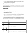
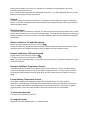
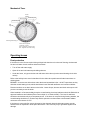
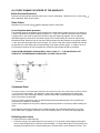
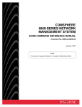
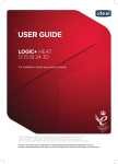
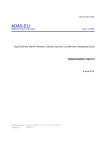
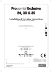
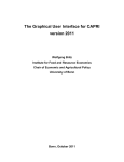
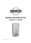
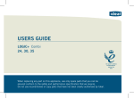
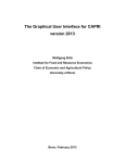
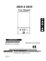
GB24 & GB30 User Manual BOILER OUTPUT To Domestic Hot Water:To Central Heating: GB24/30 Minimum 8.0 kW (27,296 Btu/h) GB24 Maximum 24.2 kW (82,570 Btu/h) GB30 Maximum 30.3 kW (103,384 Btu/h) GB24/30 Minimum 8.0 kW (27,296 Btu/h) GB24/30 Maximum 24.2 kW (82,570 Btu/h) Morco House, Riverview Road, Beverley, East Yorkshire, HU17 0LD Morco Products Ltd Tel:+44 (0) 1482 325456 Fax: +44 (0) 1482 212869 Website:www.morcoproducts.co.uk UIN 209783 A03 April 2014 Introduction The Morco GB is a wall mounted, room sealed, condensing combination boiler, featuring automatic spark ignition and fan assisted combustion. The Morco GB is a combination boiler providing both central heating and instantaneous domestic hot water (DHW) for taps and showers. Due to the high efficiency of the boiler, condensate is produced from the flue gases and this exits the boiler through a plastic waste pipe at the base of the boiler. A condensate ‘plume’ will also be visible at the flue terminal. The boiler has a number of safety features that will stop it working when problems are detected. The fault codes that are shown on the boiler status display “D” identify the problem. Once the fault is corrected the boiler can be reset using the mode control knob “A”. A list of fault codes can be found on page 8. The boiler features a preheat function that allows the boiler to occasionally fire on its own to keep the water within the boiler hot. This improves the speed with which hot water is delivered to taps or showers. This function can be switched off if required. Boiler Controls Legend A. Mode Control Knob B. DHW/Preheat Control Knob C. CH Control Knob D. Boiler Status E. Burner ‘ON’ Indication F. Pre Heat on/off Indication G. Programmer H. Pressure Gauge J. Condensate Drain K. Gas Isolation Valve (on position Shown) Safety The boiler must be installed, commissioned and maintained to the standards relevant to the country in which the home is located. It is essential that the instructions in this booklet are strictly followed, for safe and economical operation of the boiler. Electricity Supply This appliance must be earthed. Supply: 230 V ~ 50 Hz. The fusing should be 3A. Important Notes This appliance must be operated with the front casing correctly fitted and forming an adequate seal. If the boiler is installed in a cupboard then the cupboard MUST NOT be used for storage purposes. If it is known or suspected that a fault exists on the boiler then it MUST NOT BE USED until the fault has been corrected by a qualified and competent Gas Installer. Under NO circumstances should any of the sealed components on this appliance be used incorrectly or interfered with. This appliance must be operated with supervision to ensure safe operation from the ages of 8 years and above, including people with reduced physical, sensory or mental capabilities. Any maintenance or cleaning shall not be completed without supervision. In cases of repeated or continuous shutdown a qualified and competent Gas Installer, should be called to investigate and rectify the condition causing this and carry out an operational test. Only the manufacturer’s parts are to be used for replacement Minimum Clearances around the Boiler Clearances of 165mm above, 100mm below, 2.5mm at the sides and 450mm at the front of the boiler casing must be allowed for servicing. The clearance below the boiler can be reduced to 5mm after installation provided an easily removable panel is fitted, to enable the consumer to view the system pressure gauge, and to provide the 100mm clearance required for servicing. Boiler Operation To light the boiler Refer to Boiler Controls Diagram CHECK THAT THE ELECTRICITY SUPPLY TO BOILER IS OFF. Set the mode control knob (A) to ‘off’. Set the Domestic Hot Water temperature control (B) and Central Heating control knob (C) to ‘max’. Ensure that all hot water taps are turned off. Switch ON electricity to the boiler and check that all controls, e.g. boiler mechanical timer “G” and optional room thermostat, are ON (refer to mechanical 24 hour timer instructions). Set the mode knob control (A) to winter ( ). If there is central heating demand or if a hot tap is opened the boiler will ignite showing burner status (E). Note. In normal operation the “boiler status display” (D) in the Boiler Controls diagram) will show one of the following codes: DISPLAY CODE ON BOILER status Burner Off The boiler is in standby mode awaiting either a central heating call or domestic hot water demand. 0 status Burner Off The boiler has a call for central heating but the appliance has reached the desired temperature set on the boiler. C status DESCRIPTION Burner Off d status Burner On C status Burner On d status Burner On P status Burner On F The boiler has a call for domestic hot water but the appliance has reached the desired temperature set on the boiler. The boiler is operating in central heating mode. The boiler is operating in domestic hot water mode. The boiler is operating in pre heat mode. The water in the central heating circuit is less than 5ºC. If heating is switched on, this display code will change to “c”. This indicates that the frost stat is in operation. During normal operation the “burner on” indicator (E) in the Boiler Controls diagram) will remain illuminated when the burner is lit. Note: If the boiler fails to light after five attempts the fault code “L-2” will be displayed. Refer to the fault finding section on page 8 of this user manual. Preheat Pre-heat is enabled if the pre-heat indicator (F) in the Boiler Controls diagram is visible. To switch preheat on or off move the DHW/Pre-heat control knob (B) fully clockwise and then return it to the required DHW temperature setting. Reset Procedure To reset boiler after a fault has been detected, turn the mode control knob (A) fully clockwise to the reset position and immediately turn knob back to required setting. The boiler will repeat the ignition sequence if heating or domestic hot water is required. If the boiler still fails to light consult a qualified and competent Gas Installer. Winter conditions - CH and HW required. Ensure the mode control knob (A) is set to winter ( ) If heat is demanded by the optional room thermostat and/or mechanical 24 hour timer the boiler will fire and supply heat to the radiators but will give priority to DHW if any tap or shower is used. Summer conditions - HW only required. Set the mode control knob (A) to summer ( ). Turn the CH control knob (C) fully anti-clockwise. Note. The pump will operate briefly as a self-check once every 24 hours, regardless of where the control knobs are positioned. Domestic Hot Water Temperature Control o The DHW temperature is limited by the boiler controls to 64 C maximum. This will only apply when a low flow rate through the boiler occurs. A more typical temperature is 45° C but this can be increased by turning the DHW temperature control knob (B) to max and reducing the flow of water from the hot outlet. Central Heating Temperature Control o The radiator temperature is adjustable between 80 C and 45ºC via the CH control knob (C). The boiler is a high efficiency combination boiler which is most efficient when operating in condensing mode. The boiler will operate in condensing mode if the CH control knob (C) is set to the “e” position (economy mode). This control knob should be turned fully clockwise in very cold weather. To shut down the boiler Turn the mode control knob (A) to OFF To relight the boiler Repeat the procedure detailed earlier in ‘To light the boiler’. Mechanical Timer Control Indicator Timer Control Permanently ON Permanently OFF Time Indicator OFF segment ON segment 24hr Programme Ring Timer control segments 1 segment = 15mins OFF – Segments on inside of ring ON – Segments on outside of ring Operating Issues Frost protection If the home is to be left unoccupied during cold periods when there is a threat of freezing, the domestic hot and cold water circuits must be drained as follows: Turn off the cold water supply Open all hot and cold water taps including showers Under the home, only open the hot and cold water drain valves (not the central heating circuit drain valves) Refer to the holiday home owner’s handbook for the drain valve positions and further instructions on draining down. BEWARE – there are two drain valves under the home beneath the boiler - do NOT open these as they drain the central heating circuit, which should have been filled with antifreeze and corrosion inhibitor. Please note there are no drain valves on the boiler. Leave all taps, showers and drain valves open until you are next ready to use the boiler. When installed in a Caravan holiday home the central heating circuit and radiators should be filled with an approved antifreeze and inhibitor (Either Fernox Alphi 11 or Sentinel X500). The level of antifreeze should be checked annually by a competent person. If the home is occupied during freezing weather, the central heating should be run continuously and the optional room thermostat or thermostatic radiator valves set at a minimum of 15ºC. If the home is unoccupied for even a short period, the domestic hot and cold water system must be drained down as explained in bullet point three above. This is the only way to guarantee against frost damage. ALL FROST DAMAGE IS OUTSIDE OF THE WARRANTY. Boiler Overheat Protection The boiler controls will shut down the boiler in the event of overheating. Should this occur, a fault code will be displayed. Refer to fault codes. Flame Failure Should this occur a fault code will be displayed. Refer to fault codes. Loss of system water pressure The pressure gauge in the diagram below indicates the central heating system pressure. If the pressure is seen to fall below the original installation pressure of 1.5 bar over a period of time then there could be a system leak. In this event re-pressurise the boiler using the filling loop supplied. This is a flexible detachable pipe that connects the cold water supply to the central heating circuit via two taps directly beneath the boiler. When the pipe is connected open both taps until the pressure on the gauge reaches 1.5 bar, then close both taps and remove the pipe. The source of the leak must be located and resolved as repeated use of the filling loop will cause damage to the boiler and the system. If unable to do so or if the pressure continues to drop a qualified and competent Gas Installer should be consulted. LOW SYSTEM PRESSURE IS INDICATED BY FAULT CODE “F1” - THE BOILER WILL NOT OPERATE IF THE PRESSURE HAS REDUCED TO LESS THAN 0.3 BAR. Pressure Gauge Condensate Drain The boiler produces a clear liquid called condensate which leaves the boiler via an internal trap and a drain marked “J” on the boiler controls diagram. This appliance is fitted with a siphonic condensate trap system that reduces the risk of the condensate freezing. However should the condensate pipe to this appliance freeze it will need to be defrosted. If you do not feel competent to carry out the defrosting instructions below please call a qualified and competent Gas Installer for assistance. If you do feel competent to carry out the following instructions please do so with care when handling hot items. If this appliance develops a blockage in the condensate pipe, the condensate will build up to a point where it will make a gurgling noise prior to the boiler stopping and an “L2” fault code being displayed. Defrosting Instructions To unblock a frozen condensate pipe; 1. Follow the routing of the plastic pipe from its exit point (”J” on the boiler control diagram) through its route to its termination point. Locate the frozen blockage. It is likely that the pipe is frozen at the most exposed point external to the caravan holiday home or where there is some obstruction to flow. This could be at the open end of the pipe, at a bend or elbow, or where there is a dip in the pipe in which condensate can collect. The location of the blockage should be identified as closely as possible before taking further action. 2. Apply a hot water bottle, microwaveable heat pack or a warm damp cloth to the frozen blockage area. Several applications may have to be made before it fully defrosts. Warm water can also be poured onto the pipe from a watering can or similar. Do NOT use boiling water. 3. Once the blockage is removed and the condensate can flow freely, reset the appliance. (Refer to “reset procedure”) 4. If the appliance fails to ignite, call a qualified and competent Gas Installer. Preventative Steps During cold weather, set the CH control knob “C” to maximum, (return to original setting once cold spell is over) Place the heating on continuous and turn the room stat down to 15ºC overnight. (Return to normal after cold spell). Apply insulation around the condensate pipe as it leaves the boiler until it reaches its end under the caravan. Escape of gas Should a gas leak or fault be suspected contact the Gas Supplier without delay. TURN OFF ALL GAS SUPPLIES. Do NOT search for gas leaks with a naked flame. Do NOT operate any electrical switches. Maintenance The appliance should be serviced at least once a year by a qualified and competent Gas Installer. Gas Supply This boiler will only operate on Propane gas supplied via a 37mbar regulator. The designation for this gas is I3P and G31. Butane, butane/propane mixes and automotive LPG are not suitable for this boiler. In addition the boiler requires a minimum of a 47kg propane bottle in order to work correctly and a minimum regulator size of 3.5kg/hour. Water Supply Pressure The cold water supply pressure to the boiler must exceed 0.8 bar in order to work at full power. The boiler will work at lower water pressures but the hot water temperature will be lower. The boiler will not ignite below cold water flow rates of 2 litres per minute. Shower Mixer or Mixer Taps A very common problem that causes poor hot water delivery is damage to mixer taps or shower mixers caused by frost damage. The damage to the mixers is internal and so there are no leaks visible. The problem is caused by the cold water mixing with the hot water in an uncontrolled manner within the mixer. This gives the impression that the boiler is at fault. It is simple to check if the problem is with the mixers: Turn off the cold water supply to the caravan Disconnect the 15mm hot water pipe underneath the caravan, directly below the boiler cupboard. Do not disconnect the larger 22mm pipe which is part of the central heating system. Place a bucket under the pipe Turn on the cold water supply to the caravan Hot water should now flow out of the pipe under the boiler into the bucket If this water is hot, it proves that the problem is caused by damaged mixer taps or shower mixer Replace the mixer tap that is damaged to solve the problem Fault Code Table Alternating Display Code on Boiler Auto reset Description Low mains voltage 5 boiler resets in a 5 minute period Low system pressure F 7 Yes L 5 N/A F 1 No L 1 No F 2 Yes Boiler overheat Flame loss during operation L 2 No Ignition failure L 2 No Ignition failure F 3 No F 4 Yes F 5 Yes Fan fault Flow thermistor issue Return thermistor issue Problem Solution Supply Voltage is too low Repeated problems with auto reset faults Contact electricity provider Leak from sealed CH system Pump stuck or divertor motor issue Air in gas supply after bottle change No power from PCB or faulty spark generator Condensate pipe or trap frozen or blocked/ No Gas Identify leak and fix Failed fan Replace fan incorrect/no signal Test thermistor for signal and replace if faulty incorrect/no signal Test thermistor for signal and replace if faulty Investigate individual faults Free pump or reset motor Purge air from gas system re-instate power supply or replace spark generator Defrost or unblock condensate pipe or trap Check Gas Supply Warranty Conditions The boiler is guaranteed against manufacturing defects for a period of two years from the date of commissioning. However the guarantee is subject to proof of commissioning by a qualified gas installer. This is usually in the form of a commissioning certificate. In continental Europe the warranty only covers the supply of parts and telephone advice. The warranty does NOT cover the following issues: 1. Frost damage to any part of the boiler containing water during freezing conditions. 2. The removal of sludge or hard water scale due to lack of antifreeze/inhibitor 3. Damage to electronics caused by a defective electrical supply. 4. Damage or failure caused by insect contamination or blocked water filters. 5. Loss of pressure within the heating system not caused directly by the boiler. 6. Incorrect operation of the boiler caused by defective outlets such as thermostatic mixers or mono block mixer taps. 7. Damage caused by unauthorised modifications to the boiler from original specifications. Spare Part Availability Information regarding spare parts can be found by contacting Morco’s sales office or website (details below). MORCO PRODUCTS LTD Morco House, Riverview Road, Beverley, East Yorkshire HU17 0LD Tel: +44 (0) 1482 325456 FAX: +44 (0)44 1482 212869 EMAIL: [email protected] WEBSITE: www.morcoproducts.co.uk