1
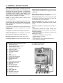
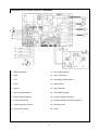
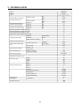
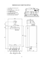
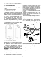
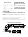
FEB-24ED SUPERCOMPACT USER
INSTRUCTIONS AND
TECHNICAL INSTRUCTIONS
BOILER OUTPUT
To Domestic Hot Water:
Water:
Minimum 7.6 kW
(25,932.26
Maximum 23.7 kW
(80,867.71
To Central Heating:
Minimum 7.6 kW
(25,932.26
Maximum 23.7 kW
(80,867.71
Btu/h)
Btu/h)
EC-TYPE EXAMINATION CERTIFICATE
PIN0099BN794
Btu/h)
Btu/h)
Morco House, Riverview Road, Beverley, East Yorkshire, HU17 0LD
Morco Products Ltd
Tel: 01482 325456 Fax: 01482 212869
WEBSITE: www.morcoproducts.co.uk
2
CONTENTS
Section
Page
1
USERS INSTRUCTIONS
4
2
GENERAL SPECIFICATIONS
8
3
TECHNICAL DATA
10
4
GENERAL INSTALLATION REQUIREMENTS
11
5
INSTALLATION INSTRUCTIONS
15
6
COMMISSIONING INSTRUCTIONS
17
7
ROUTINE SERVING INSTRUCTIONS
18
8
TROUBLESHOOTING
19
9
FAULT CODE TABLE
20
10
WARRANTY CONDITIONS
20
3
1.- USERS INSTRUCTIONS
GAS SAFETY (INSTALLATION AND USE) REGULATIONS 1998 (AS AMENDED)
It is the law that all gas appliances are installed by a registered person, in accordance with the above regulations. Failure to install appliances correctly could lead to prosecution. It is in your own interest, and that of
safety, to ensure that the law is complied with.
Read these instructions carefully before attempting to operate the appliance. Comply with all applicable warnings. Do not interfere with any sealed components, and use the appliance only in accordance with these
instructions.
INTRODUCTION
The Fagor FEB-24ED is wall hung, room sealed, fan assisted, microprocessor controlled, fully modulating
gas combination boiler for providing both central heating and domestic hot water.
7
4
3
2
FEB-24ED
1
5 6
1.-Pressure gauge
5.-Orange light. Burner on
2.-Heating service and heating temperature selector
6.-Red light lock out
3.-Main control, reset and D.H.W temperature selector
7.- Display (between both knobs)
4.-Clock
DOMESTIC HOT WATER SERVICE
Turn the left knob (3) in order to turn the boiler on. The display will show "On" indicating that the boiler is ready
to supply Domestic Hot Water (DHW) whenever there is demand for it. When a hot tap is opened the boiler
automatically fires to deliver hot water and the orange light will come on indicating the burner is on. A water
temperature of between 35° and 60° C can be selected by turning the domestic hot water temperature regulating knob. The value selected will be shown in the display when it is changed with the knob.
HOT WATER AND CENTRAL HEATING SERVICE
With the main control switch on and the display showing “On”,
turn the heating selector knob clockwise from the summer setting.. The boiler will fire up automatically when either the time
clock/room stat or boiler stat calls for central heating, or a hot tap
is opened for hot water. If a hot tap is opened the boiler gives priority to hot water delivery with the central heating on standby
until the tap is closed.
The temperature of the radiators can be selected between 60ºC
and 85ºC by turning the right knob (2) the value will be shown on
the display.
Note: If the boiler has been configured for under floor heating the temperature cannot be altered by the user
operating the control knob. Only the pre-set value set up by the installer will be available
4
USING THE PROGRAMMABLE CLOCK
1. Set the correct time by rotating the minute hand until the arrowhead
points at the correct time on the 24 hour dial.
2. Check the position of the manual override switch (just to the bottom of
the clock face). This has three positions:
-Left: is ON overriding the timer mode
-Middle is timer mode, with ON, OFF, times governed by the time clock.
-Right position is OFF. The heating will not work at all regardless of the
main boiler control switch except if triggered by the built in frost protection thermostat.
3. To set on/off times, move all the white tappets , in the outer ring,
between the required 'on' and 'off' times.to the outer position. For example, if you want the heating to come on at 6am and switch off at 10am,
move all the tappets outwards between these two times. Each tappet
represents a quarter of an hour. Set as many on/off times as required
within a 24 hour period
ON
ON
TIMER
OFF
OFF
N.B. THE TIME CLOCK MUST BE RESET TO THE CORRECT TIME IF
THE POWER SUPPLY TO THE BOILER HAS BEEN INTERRUPTED
(POWERCUTS/SEASONAL TIME ADJUSTMENT)
RED LIGHT-LOCK OUT
Should the boiler fail to ignite due to lack of gas, or component failure etc. It will “lockout” and the red light
will be displayed and the relevant fault code will be shown on the digital display.
Note: To reset, turn the left main control knob (3) to off then turn on again. If the boiler constantly locks out,
call your service engineer.
TURNING THE BOILER OFF
Turn the main control switch to the
position.
NOTE: In this position the automatic safety devices such as frost protection and anti pump seizure are still
operative. To shut down completely isolate the mains supply to the boiler.
GENERAL GUIDANCE NOTES ON HOT WATER DELIVERY
The temperature of the hot water is governed by both the ambient temperature of the cold water supply and
its flow rate through the boiler. I.E. at a flow rate of 10.0L/min there will be a maximum rise of 35ºC above
ambient. At a flow rate of 6.8L/min there will be a rise of 50ºC above ambient, (the slower the flow rate, the
greater the temperature rise).
The flow rate of the hot water is controlled by the hot outlet tap.
The temperature selector on the boiler is effective only when there is either a low water flow rate or a high
ambient water temperature.
- The boiler can theoretically supply more than one outlet simultaneously However in practice the tap which
is nearest will receive the most hot water. If the shower is in use and a kitchen tap is opened virtually all the
hot water will be diverted to the kitchen as it offers the least resistance.
- If an outlet is too restrictive it will slow down the flow rate and increase the temperature. For example the
shower - ensure the head is free from blockages caused by scale.
- Due to the restrictive nature of simple mixer showers it is wise to turn the temperature selector down on
the boiler before using the shower.
- If a tap or shower head is too restrictive due to a fault or blockage, the flow rate will be reduced to below
the rate at which the boiler is able to modulate resulting in a wide swing in temperatures. Either fix the
restriction or turn the temperature selector on the boiler down.
5
- Caution: The boiler can produce water at over 70°C when in central heating mode. If you run a hot
tap when the boiler has been heating the radiators, the initial flow through the hot tap could be very
hot. DO NOT PLACE YOUR HANDS under the tap or use the shower until this initial flow has passed.
- Allow time (30 seconds) for the temperature to stabilise after making an adjustment at the tap
before making further adjustments.
APPLIANCE SAFETY LOCK-OUT
Whenever a malfunction is detected in the boiler, the boiler switches off automatically and the red LED lock-out indicator lights up along with the digital display (see P19)
To reset the boiler turn the left main control knob (3) to the
position and go back
to the chosen position. Some lockout sequences require the sensors to cool to within normal operating temperatures before the boiler will reset. The red indicator light
should go out. IMPORTANT: Whenever the boiler has been left idle for any length of
time, or when a new gas bottle is installed (propane models), the appliance may
switch off due to the presence of air in the pipes. In cases such as these, repeat the ignition operation until
all of the air has been purged from the system.
FROST PROTECTION
Providing the boiler power supply and gas supply is connected the boiler will automatically fire on minimum
when near freezing conditions are detected. When the temperature in the system reaches 20°C it will
switch off. For winter storage see notes at the end of this section.
NOTE: It is still necessary to drain the domestic hot and cold water system.
ANTI PUMP SEIZURE DEVICE
When central heating is not being used, but the boiler is in the summer setting (for domestic hot water only)
the pump will automatically run for 30 seconds every 23 hours to prevent it seizing. If the appliance has been
shut down with the electrical supply switched off for a period, this device will not work. The pump may be
found to have jammed when the appliance is switched back on. If so, consult your installer or service engineer.
NOTE: Seized pumps are not covered under warranty.
PRESSURE GAUGE
The pressure gauge should indicate approximately between 0,8 and 1,6 bar. If the pressure is seen to
decrease over a period of time there is a water leak on the central heating system.
The boiler is fitted with a safety device to prevent it working below a pressure of 0.8 bar.
ROUTINE SERVICING
To ensure continued safe and efficient operation of the appliance it is recommended that it is checked and
serviced as necessary at regular intervals. The frequency of servicing will depend upon the particular installation conditions and usage but in general once a year should be regarded as a minimum even if only occasional usage has occurred.
It is the law that any service work MUST be carried out by a competant gas registered engineer.
SAFETY
It is essential that these instructions are strictly followed for the safe and economical operation of this appliance. The appliance is a fan-assisted room sealed gas boiler and therefore the flue terminal MUST NOT BE
OBSTRUCTED under any circumstances. If it is damaged, turn off the appliance and consult your installer,
or service engineer. If it is known or suspected that a fault exists on the appliance it MUST NOT be used until
the fault has been rectified by a competant gas registered engineer.
6
PRECAUTIONS AGAINST FREEZING DURING WINTER STORAGE
If the holiday home is to be un-occupied during cold periods, and whenever there is a threat of freezing, the
domestic hot and cold water circuit must be drained as follows:
-Turn off the cold water supply.
-Open all hot and cold taps.
-Open all drain plugs in the hot and cold water system (Do not drain the central heating circuit which should
have been filled with antifreeze) If the boiler is installed in a Caravan Holiday Home, refer to the user
manual for the home, for the positions of all drain plugs.
Note: There are no drain plugs fitted to the actual boiler.
-Leave all taps and plugs open until the boiler is next needed for service. This will allow any residual water to
continue to drain.
NOTES ON FROST PROTECTION
The boiler inbuilt frost protection feature is designed primarily to prevent damage to the heating circuit and radiators. It will not protect the hot and cold water pipes from freezing under the holiday
home and will provide only a limited protection to the boiler pipework and hot and cold pipework
inside the holiday home.
The heating circuit and radiators should contain the correct level of antifreeze to prevent damage
during freezing conditions and should not be drained down.
For the frost feature to work, the gas supply must be left on and the electrical power supply (wall
socket), must be connected and switched on, the central heating control knob on the boiler must be
in the off position.
Do not rely on the boiler frost protection to prevent freezing of the hot and cold water pipes,
including those inside the boiler during severe frost conditions, it will not.
ALL FROST DAMAGE IS OUTSIDE OF THE WARRANTY
7
2.- GENERAL SPECIFICATIONS
The Fagor FEB-24ED is a wall hung, room sealed,
fan assisted, microprocessor controlled fully modulating gas combination boiler for providing both central heating and domestic hot water. It is particularly
suitable for Caravan Holiday Home and Park Home
use. Maximum heat output in either heating or hot
water mode is 23.7.kW (80.840 Btu/h), and priority is
always given to the supply of hot water.
Central heating expansion vessel.
Differential air pressure switch. Prevents the boiler firing if there is insufficient air supply due to a fault
or blockage.
Water pressure switch. Prevents the boiler firing if
there is less than 0.5 bar in the system.
NOTE: The central Heating power is factory set at
70% of its maximum.
Thermistors (NTC) There are two thermistors fitted
for automatic control of the domestic hot water and
the central heating flow temperature.
The appliance flue is supplied seperately with a concentric air/flue duct and wall terminal, however additional extension kits, vertical flue kit are available as
optional extras.
Safety thermostat Shuts down the boiler in the
event of overheating. Resets after a few minutes
cooling
Electronic controls, incorporating the following features:
The appliance is intended for use with sealed central
heating systems and is supplied for use with
propane gas.
- Temperature selection for central heating from
between 60 to 85°C (Pre-set between 40º to 60ºC for
under floor heating).
- Temperature selection for domestic hot water from
between 35 to 60°C.
- Continuous modulation of the gas valve.
- Flame control by ionisation
- Ignition control
- Anti-frost control in the central heating circuit.
- Anti - seizure of the pump.
The appliance includes the following components:
Induced draught fan for the extraction of combustion products and induction of combustion air.
Modulating gas valve with double safety valves
Circulation pump with manual anti-seizure device
Schematic diagram- Hydraulic circuit
1.- Expansion vessel
2.- Pump with Automatic air bleed
3.- Water pressure switch
4.- Central heating thermistor
5.- Three way valve
6.- High limit thermostat
7.- Air pressure switch
8.- Venturi
9.- Fan
10.- Sealed air box
11.- Copper heat exchanger
12.- Combustion chamber
13.- Ignition electrode
14.- Burner
15.- Flame sensing electrode
16.- Modulating gas valve
17.- Gas inlet
18.- D.H.W Thermistor
19.- Hot Water outlet
20.- Plate heat exchanger
21.- C.H flow
23.- Cold water inlet
24.- C.H return
25.- Pressure relief valve
26.- Automatic By-pass
27.- Expansion vessel valve
28.- Draining valve (C.H.)
8
FEB-24ED ELECTRICAL CIRCUIT DIAGRAM
1.- Mains Connection
11.- Room Stat (optional)
2.- Earth
12.- Clock Connection
3.- Fan
13.- Modulating Solenoid Valve
4.- Pump
14.- Flame Sensor
5.- Ignition
15.- High Limit Stat
6.- Burner Solenoid Valve 1
16.- Hot WaterThermistor
7.- Burner Solenoid Valve 2
17.- Central Heating Thermistor
8.- Front Panel Control
18.- Central Heating Low Pressure Switch
9.- 3 Way Valve Micro Switch
19.- External Probe
10.- Air Pressure Switch
20.- Clock
9
3.- TECHNICAL DATA
Model
FEB-24ED
Category
II2H3P
Type
Central heating and domestic
hot water performances.
C12,C 32,C 42,C52,C 82,B22
kW
Maximum output
Btu/h
kW
Minimum output
Btu/h
23.7
80,840
7.6
26,151
Nominal central heating and
domestic hot input (Gross)
Maximum
kW
28.9
Minimum
kW
9.2
Nominal central heating and
domestic hot water input (Nett)
Maximum
kW
26
Minimum
kW
8.3
Domestic hot water flow rate at 25ºC (l/min)
13.6
Domestic hot water flow rate at 35ºC (l/min)
9.7
Nominal D.H.W. flow rate at 34ºC ( l/min)
10
Minimum flow rate for activating D.H.W. (l/min)
Operating pressure (bar)
2
Maximum
Central heating
Maximum
D.H.W
Minimum D.H.W. activation
Gas inlet pressure (mbar)
Gas consumption (Hi)
7
Central heating circui t
Floor heating
40-60
35-60
20
Propane G -31
37
Natural G -20 (m3/h)
2.75
Propane G -31 (kg/h)
2.04
230V~50Hz
120
Height
680
Width
390
Depth
254
Top
200
Bottom
150
Sides
5
Front
5
Gas inlet
3/4 BSP
Domestic cold water inlet
1/2 BSP
D.H.W.outlet
1/2 BSP
Central heating flow
3/4 BSP
Central heati ng return
3/4 BSP
Net weight (kg)
Type of gas
60-85
Natural G -20
Max.power consumptio n (W)
Minimum clearance (mm)
Radiators
D.H.W.circuit
Electrical supply (V/Hz)
Dimensions (mm)
10
0.3
Expansion vessel capacity (1)
Temperature selection range
(ºC)
2.5
29
Propane G -31
X
∗∗
92/42/EEC Directive
10
DIMENSIONS AND CONNECTIONS DETAILS
1.- 3/4” BSP Central heating return
2.- Mains cable
3.-1/2” BSP Domestic cold water inlet
4.- 3/4” BSP Gas inlet
5.- 1/2” BSP D.H.W. outlet
6.- 3/4” BSP Central heating flow
8.- Pressure Relief Valve
9.- Draining valve for central heating
T.A.:Room thermostat connection
DHW
9
7
50
100
6
5
4
1
3
2
3
CH FLOW
8
T.A.
GAS DCW CH RETURN
INLET
11
4.- GENERAL INSTALLATION REQUIREMENTS
4.1 RECOMMENDATIONS
- Ventilation requirements as stated in this manual
must be observed.
- Minimum clearance as stated in the technical data
must be observed.
FOR THE USER
This appliance must be installed, adjusted or adapted for use with another type of gas, only by a qualified and competent person.
Its quality and a correct installation will ensure that
your heater works properly.
4.3 FLUE TERMINAL POSITION
- The boiler MUST be installed so that the terminal
is exposed to the external air.
- It is important that the position of the terminal
allows free passage of air across it at all times.
- It is ESSENTIAL TO ENSURE, that products of
combustion discharging from the terminal cannot reenter the building, or vehicle, through ventilators,
windows, or other sources of natural air infiltration,
such as other flues etc, with the exception of doors,
but not the opening windows thereof.
- The minimum acceptable dimensions from the terminal to obstructions and ventilation openings is as
follows:
GAS SAFETY (INSTALLATION AND USE) REGULATIONS 1998 (As amended).
It is the law that all gas appliances must be installed
by a registered person, in accordance with the above
regulations.
Failure to install appliances correctly may lead to
prosecution.
It is in your own interest, and that of safety, to ensure
that the law is complied with.
In addition to the above regulations, this appliance
must be installed in accordance with the current IEE
Wiring regulations, Heath and Safety Document No
635 'The Electricity at Work Regulations.
It should also be in accordance with the relevant recommendations in the current editions of all relevant
National Standards. Your particular attention is
drawn to the following standards relevant to an
installation in Leisure Accommodation Vehicles:
BS 5482 part 2 Installations in caravans and non
permanent dwellings.
BS 5482 Part 3 Installations in Boats
BSEN721 Leisure accommodation vehicles ventilation requirements.
BSEN 1949 Installation of LPG System for
Habitational Purposes in Leisure Accommodation
Vehicles.
IMPORTANT: Manufactures instructions must NOT
be taken in any way as over-riding statutory regulations.
Directly below an opening fixed vent
windows, etc.
300mm
Adjacent to an opening fixed vent
windows, etc.
300mm
Below gutters.
75mm
Below eaves
200mm
From a vertical drain pipe or soil pipe
75mm
From an internal or external corner
300mm
Vertically from a terminal on the same
wall
1500mm
Horizontally from a terminal on the
same wall
300mm
Where the terminal is fitted in a position to which
children, the elderly, or disabled people have access
(less than 1.5m above steps, decking or ground), a
suitable terminal guard should be fitted.
In certain weather conditions the terminal may emit
a plume of steam.
4.2 BOILER LOCATION
In positioning the boiler, the following limitations
MUST be observed:
The position must allow for a suitable flue termination to be made.
The combination boiler must be installed on a flat
vertical wall capable of supporting its weight .
- If the boiler is in a room containing a bath or shower, the boiler controls and power supply must be so
situated that they can not be touched by the person
using the bath or shower. Attention is drawn to the
current IEE Wiring Regulations, and in Scotland the
electrical provisions of the Building Regulations
applicable in Scotland.
- A compartment used to enclose the appliance
MUST be designed and constructed specifically for
the purpose. An existing cupboard, or compartment,
may be used provided it is modified accordingly.
4.4 MINIMUM CLEARANCES
Minimum clearances of 5mm to the front and sides
of the boiler must be observed. However full access
from the front in the form of an opening door, must
be given to allow access to the controls and for servicing.
200mm above the top of the boiler case is required
for the flue assembly.
150mm is required below the boiler to allow easy
access to the gas isolation cock.
12
4.4 VENTILATION REQUIREMENTS
The following notes are for general guidance:
- The Morco FEB-24ED is a room sealed appliance
and needs no purpose provided combustion air ventilation.
- If the boiler is to be built into a small cupboard or
compartment (i.e. at minimum clearances)and overheating can be forseen (i.e. close proximity to a cooking appliance etc) permanent air vents are recommended for cooling purposes in the cupboard or
compartment . The following table gives the minimum
effective areas of the vents.
Air from room/int
space
Air direct from
outside
HIGH LEVEL
13000 mm2
7500 mm2
LOW LEVEL
13000 mm2
7500 mm2
4.8 REQUIREMENTS
WATER SYSTEMS
FOR
SEALED
The heating system design should be based on the
following information:
- The available pump head is given below.
- A minimum flow rate corresponding to a heating differential of 20°C must be obtained at all times.
- A heating by-pass should be fitted to ensure that
the above condition is satisfied. If thermostatic radiator valves are to be installed, at least one radiator
should be without a thermostatic valve (usually the
bathroom radiator).
4.5 ELECTRICITY SUPPLY
A 3 amp fused three pin plug for use with 230V-50Hz
is supplied fitted to the appliance.
- A sealed system must only be filled by a competent
person using an approved filling loop connected
between the mains water supply pipe and the central
heating return pipe. Once filled the loop should be
disconnected and left adjacent to the boiler.
AVAILABLE PUMP FEAD
It should be used with a shuttered socket outlet complying with BS 1363
THIS APPLIANCE MUST BE EARTHED
4.6 GAS SUPPLY
- A Propane gas supply at 37m bar is required.
Pressure (mbar)
Position of air
vent
- Prior to filling the central heating system (see section 6.2) It is recommended that where the system is
installed in a caravan holiday home, subject to non continuous use, anti-freeze is used.
500
400
300
200
100
Flow (l/h)
0
0
200
by-pass closed
- Ensure the regulator is of sufficient capacity to
carry the maximum boiler input plus the demand for
any other installed appliances.
- Ensure the connection between the supply/bottle
and the caravan holiday home or park home is
designed so that no pressure drop occurs.
- No more that 3 m of 15mm pipe should be used.
Where the supply exceeds 3 m the pipe should be
suitably sized only reducing to 15mm before the boiler
- A full bore isolation cock must be fitted in the supply close to the boiler or use morco part number
FW0391.
- The complete installation must be tested for gas
soundness.
4.7 WATER SYSTEMS - GENERAL
- This appliance is designed for connection to sealed
central heating water systems.
13
400
600
800
1000
by-pass open
- The fol-
lowing paragraphs outline the specifications of the
items fitted to the boiler.
- If the appliance is installed in an area where the
temporary hardness of the water supply is high, say
Expansion vessel.
D H W Performance graph
The following table gives the maximum system volume that the integral 7 l expansion vessel can sustain
under different temperature conditions. If the system
volume exceeds that shown, an additional expansion
vessel must be fitted and connected to the heating
system primary return pipe as close as possible to
the appliance. If an extra vessel is required, ensure
that the total capacity of both vessels is adequate. If
the pressure gauge indicates 2.2 bar or greater when
the appliance is at maximum temperature with all
radiators in circulation an extra expansion vessel is
required.
60 °C
7.55 l/min
60 °C
2.42 l/min
55
49 °C
10 l/min
50
45
40
35
35 °C
10 l/min
35 °C
5.45 l/min
30
25
20
1
2
3
4
5
6
7
8
9
10
11
12
13
14
FLOW D.H.W. (l/min)
COLD WATER INLET TEMPERATURE =15ºC
over 150 ppm, the fitting of an in line scale inhibitor
may be an advantage.
P
2,2
- Devices capable of preventing the flow of expansion water: e.g. non return valves and/or loose jumpered stop cocks should not be fitted unless separate arrangements are made for expansion water.
2,0
1,8
85º C
1,6
75º C
60º C
- If a non-return valve is fitted in the incoming water
supply - e.g. in line with scale inhibitor then a D.H.W.
expansion vessel MUST be obtained and fitted.
1,4
1,2
1
60
50
100
150
200
250 C
P Cold pressure (bar)
C System capacity (litres)
Pressure relief valve
A pressure relief valve set 3 bar (43.5psi) is fitted and
a discharge pipe is routed to the outside of the appliance. This discharge pipe should be extended to terminate safely away from the appliance to a point
where a discharge would not cause damage to persons or property but would be detected. The pipe
should be able to withstand boiling water, be a minimum of 15mm in diameter, and not include any
upward pipe runs or horizontal runs prone to freezing.
4.9 D.H.W. SYSTEMS
- For specific information relating to fittings (example:. Shower, washing machines etc.) suitable for
connection in the D.H.W. circuit, consult the Local
Water Undertaking, however the following information is given for guidance.
Domestic hot/cold water supply taps and mixing
taps - All equipment designed for use at mains water
pressure is suitable.
Showers - Any mains pressure shower is suitable,
but if the unit has a loose head which may become
immersed in bath water either an anti-syphonage
device must be fitted, or the length of the flexible
hose must be reduced so that it cannot fall closer
than 13 mm (1/2 in) to the top of the bath.
- Check that mains supply pressure is within the prescribed limits (refer to 'technical data' page 7) If necessary, a pressure reducing valve should be fitted to
the mains supply before D.H.W. inlet connection.
- The DHW performance is summarised in the graph:
- The final 1000 mm (40 in) of the mains supply pipe
to the boiler must be copper.
14
5.- INSTALLATION INSTRUCTIONS
5.1 BOILER PACKAGING
mostat is 24V (normally closed). Any 24V controls
may be used, but gold contacts are recommended.
The boilers are supplied in different packagings:
DO NOT under any circumstances use a mains supply to the stat as you will damage the P.C.B.Only voltage free switching stats should be used.
- Boiler
- Flue system (separate packaging)
5.2 FITTING THE BOILER.
- Decide where the boiler is to be fixed on the wall
taking into account the installation requirements
detailed in section 4.2 and the clearances and dimensions described in the the technical data.
The centres for the hanging strap fixing are 85mm
below the top of the boiler casing, see fig below.
The flue pipe centre is 213mm above the hanging
strap centres. NOTE: a fall of about 2º - 3º should be
allowed on the flue pipe to stop water ingress into the
boiler.
Connection of a room thermostat (optional).Proceed
as follows:
Unscrew the screw (A) as it shows figure 1, open
the bottom cover, where the connector of the room
thermostat is placed.
Press out the plastic disc (B) using a screwdriver to
form a hole so you can pass through the wires of the
room stat.
Replace cover.
The room thermostat must be installed on a wall
which is free from any objects and free from direct
contact with either sunlight or draughts.
A screw fixing should be made on the bottom rail of
the boiler to secure it during transport.
Figure 1
1
A
2
B
Black
Wires
3
3
TMV2
External Probe
5.3 WIRING INSTRUCTIONS
Thermostat
Warning: observe the usual precautions to ensure
that the electricity supply is isolated before commencing any installation or service work.
- The appliance is fitted with a 3 amp. fused 3 pin
plug for use with 230 V~50Hz. It should be fitted to a
shuttered socket outlet complying with BS 1363
WARNING: THIS APPLIANCE MUST BE
EARTHED.
ROOM THERMOSTAT:
External Probe connection Type 10K-25ºC, B3435
1% (25-85) (where available).
Press out the plastic disc (B) using a screwdriver to
form a hole so you can pass through the wires of the
external probe.
Conect the external probe wires to the free holes
with red wires in the other side..
Configurate the external probe curve in instalation
menu.
This appliance may be used in conjunction with an
external room thermostat.
The voltage between the contacts of the room ther-
15
External Probe Curves
5.4 WATER AND GAS CONNECTION
Connect the boiler up in such a way as to leave the
connecting pipes self supporting and free from any
stress.
Check that the gas pipe complies with the requirements of section 4.6
In order for the boiler to function correctly and to have
a long working life, the central heating system must
be properly designed, making sure that the temperature difference between the flow and the return will
not be greater then 20°C.
5.5 AIR/FLUE SYSTEM
The flue system is a part of the appliance and is approved as such. Use only flue systems supplied by Morco
witch are approved for use with this boiler.
The standard flue kit for the FEB-24ED is a 600mm horizontal coaxial air/flue kit (part number RSF003), as
shown below.
There are various other options available, including a vertical flue kit.(part number RSF040)
Please ask for details.
The horizontal pipe may be cut down to the length required. The flue must be fitted with a .2° or 3° downwards incline to prevent any water or condensation from entering in the boiler.
Where a short run of less than 1 m is used, such as in a caravan holiday home, the air restrictor ring
must be inserted into the boiler flue spigot before fitting the elbow.
HORIZONTAL FLUE Ø 60-100mm COAXIAL
25°
15
25
25
498
860
585
927
20
Ø60.8
Seal
95
Rubber
sleeve
50
Clamp
Air
restrictor
ring
L
16
Ø 60-100 Coaxial pipe
L= 0.5 m
L= 1 m
6.- COMMISSIONING INSTRUCTIONS
Before commissioning the appliance, the whole gas
installation including the meter (if fitted) MUST be
purged and tested for gas soundness.
IMPORTANT: open all doors and windows, extinguish naked lights, and DO NOT SMOKE whilst
purging the gas line.
Before commencing the commissioning procedure,
ensure that the central heating system and the
domestic hot and cold water system have been
flushed. This will remove contamination which could
block the filters fitted to the cold inlet and C.H. return
connections resulting in incorrect functioning of the
boiler.
6.3 GAS CIRCUIT
Purge the gas circuit as described above. Turn on
the gas cock to the installation and check that there
are no leaks using leak detection fluid.
6.4 SETTINGS
Before leaving the factory the boiler is pre-set in
accordance with the information on the data plate,
and therefore needs no further adjustment.
6.5 INITIAL OPERATION
6.5.1 Preliminary warnings
Turn on the Mains cold water isolation valve..
- Make sure that the central heating circuit is
completely full and vented. The pressure gauge
should indicate a pressure of between 0.8 and 1.6
bar.
Fill and vent the installation by turning on the various
hot water taps in the installation
- Make sure that the air intake and the flue outlet are
not blocked.
Make sure that there are no leaks in the installation.
6.5.2 Domestic hot water service
6.2 CENTRAL HEATING CIRCUIT
To turn on the boiler turn the main control switch, the
green light shows, or ‘ON’ can be seen in the display.
The boiler is then ready to supply D.H.W. on demand.
6.1 DOMESTIC HOT WATER
In order for the boiler to function correctly, the pressure in the central heating circuit must be between
0.8 and 1.6 bar when cold.
Both the boiler and the central heating installation
must be purged of any air in the water pipes which
may cause noise/malfunctions/damage to the boiler.
The boiler is fitted with an automatic air vent always
ensure that the vent cap is loose prior to
comissioning.
In order to fill the installation correctly the following
sequence must be followed:
- Open one or more radiator bleed vent screws.
- Fill the central heating circuit using the approved
method given in section 4.8
- Turn off each of the air vents as water starts to
appear from them.
- Turn off the filling tap when the pressure gauge
exceeds 1.6 bar.
- Turn the main control switch to the winter setting,
making sure that the pump runs. The pump will not
run if there is insufficient pressure.
- Vent the central heating circuit once more. Then let
the pressure in the circuit settle at 1.6 bar. If
necessary open the pump drain to reduce the pressure in the system.
- Make sure that there are no leaks in the installation.
Whenever a hot tap is opened the boiler automatically fires up to deliver hot water. The temperature
selector control should be set at maximum. If the
ambient water temperature is high (as in a hot climate) then the hot water temperature may be
reduced by using this knob.
6.5.3 Hot water and central heating service
Set the tappets on the time clock to an on position
and the main control switch on so the green light is
on. The room stat (if fitted) to max temp. Then turn
the central heating selector clockwise. The boiler will
fire up. By means of the central heating temperature
selector control knob, any water temperature of
between 60 and 85°C, may be seleced. The boiler
will remain on until the temperature selected on the
room thermostat or on the boiler itself is reached.
NOTE: If the boiler has configured for under floor
heating then only the temperature entered in the
installer menu will be available. turning the control
knob will have no effect.
Whenever there is a demand for D.H.W. on the central heating setting, the boiler is ready to supply it giving priority to the D.H.W. with the central heating on
standby until the D.H.W. demand ceases.
6.5.4 Turning the boiler off
- Turn the main control switch to the
- Turn off the gas supply to the boiler.
17
setting.
6.5.5 Appliance safety lock-out
6.7 USER’S INSTRUCTIONS
If the boiler developes a fault the red LED will iluminate, and the digital display show the relevant fault
code (see P19)
Upon completion of testing the system, the installer
should:
To restart the boiler Set the main control on the
position and then turn it back to the chosen position.
The red LEDshould go out.
IMPORTANT: Whenever the boiler has been left idle
for any length of time, or when a new gas bottle is
installed (propane models), the appliance may switch
off due to the presence of air in the pipes. In cases
such as these, the main control switch may be turned
to
position several times until all the air is
expelled.
6.6 FINAL CHECKS
- Re-light and test for gas soundness
- Set the C.H. and D.H.W. temperature selectors to
the required settings.
- Ensure that the time clock and/or room stat (if
fitted) are set to the required setting (s).
- Give the 'users Instructions' to the owner and
emphasise their responsibilities under the "Gas
Safety (Installation and Use) Regulations 1998"
- Explain and demonstrate the lighting and shut
down procedures.
- Advise the owner on the efficient use of the system,
including the use and adjustment of all system controls for both D.H.W. and C.H.
- Advise the user of the precautions necessary to
prevent damage to the system, and to the building, in
the event of the system remaining inoperative during
frost conditions.
- Explain the function of the boiler lock-out devices,
and how to reset it. Emphasise that if cut - out
persists, the boiler should be turned off and the
installer or service engineer consulted.
- Stress the importance of an annual service by a
competent gas registered engineer.
7.- ROUTINE SERVICING INSTRUCTIONS
To ensure continued efficient operation of the appliance, it is recommended that it is checked and serviced as necessary at regular intervals. The frequency of servicing will depend upon the particular installation conditions and usage but in general once a
year should be adequate.
distance may be reduced to 5 mm, as long as a door
is installed which can be removed when it comes to
carrying out maintenance work.
It is the law that any service work must be carried out
by a competent gas registered engineer.
Before commencing any service operation, ISOLATE
the mains electric supply, and TURN OFF the gas
supply at the main service cock. Service the appliance by following the full procedure detailed below.
MINIMUM CLEARANCE REQUIRED FOR SERVICING AND REPLACEMENT OF PARTS
* Distance at the side
The minimum distance necessary for carrying out
maintenance operations, is 5 mm
* Distance at the top
The minimum distance necessary for carrying out
maintenance operations, is 200mm
* Distance at the bottom
FRONT COVER REMOVAL
The minimum distance necessary for carrying out
maintenance operations, is 250 mm.
The cover is held in place by four spring clips and can
be removed by grasping it at the top and pulling forward sharply to release.
* Distance at the front
The minimum distance necessary for access during
maintenance operations, is 250mm, although this
Further access can be gained by removing the control panel. (Four screws), and moving down the electronic box.
18
FAN CLEANING
Remove the fan (3 screws) and using a soft brush
remove any build up of debris from the fan blades.
BURNER AND HEAT EXCHANGER
INSPECTION AND CLEANING
The front of the sealed air box must first be removed
(8 screws) and care should be taken to avoid damaging the seal. The combustion chamber cover can
then be removed (6 screws) and gas connections
taking care not to damage the delicate insulation
material inside.
Inspect the burner and heat exchanger fins for debris
and soot. Check also for rubbish below the burner.
IGNITION
TRODES
AND
DETECTION
ELEC-
With the combustion chamber cover removed check
the condition of the electrodes for any sign of wear or
damage.
WATER CIRCUIT CHECKS
Inspect the pipe work inside the boiler for leaks.
Check that the pressure in the system is correct (0.8
to 1.6 bar).
rises. Finally check the filters which is situated in the
cold water inlet pipe
BURNER PRESSURE
This is factory set, but should you suspect a problem
proceed as follows: There is an easily accessible
burner pressure nipple on the gas feed pipe, between
the burner and the modulating gas valve.
The burner pressure nipple should give a reading of
35 mbar when the boiler is at full power on D.H.W.
mode. Remove the main cable plug to the gas valve
to get a minimum burner pressure reading which
should be 4,4 mbar.N.B. There is a logic program
built into the central heating enabling it to detect
when it is connected to a small system. This may prevent the burner from firing on full (max press) so
ensure burner pressure is only tested in DHW mode.
FINAL CHECKS
Turn all the controls to their max position so that the
appliance begins to function. Check for gas leaks
using a suitable detector.
Check the boiler functions correctly in both central
heating and domestic hot water modes. The green
light will start flashing when the boiler is firing in either
mode. Check the amber LED iluminates when a
flame is detected in either central heating or domestic hot water modes.
Check the correct operation of the gauge. The pressure should increase slightly as the temperature
8.- TROUBLESHOOTING
COMMON PROBLEMS
1. Hot water temperature at the taps will be reduced, as the temperature of the mains cold water supply is
colder during the winter period.
2. The gas supply to the boiler has run out, or is about to run out, near empty propane gas bottles will supply
enough gas to run low power appliances such as cookers and gas fires, but will fail to supply high powered
appliances such as the combination boiler.
3. During busy periods, the mains cold water supply to the boiler may be subjected to variations in pressure,
this will result in fluctuations in the hot water temperature at the hot water outlet.
4. If the mains power supply to the boiler has been interrupted or turned off, then the time clock on the boiler must be reset to the correct time, if the boiler is to be operated in the timed sequence in central heating
mode.
The FEB-24ED has a self diagnostic system built into its printed circuit board. Should a safety related, or
various other faults occur, then the boiler will failsafe by locking out, which is indicated by the red LED on the
control panel. The fault can be identified by the code in the LED display. The electronic failsafe is also backed
by a mechanical means of protection, should the electronics fail to detect a fault.
These mechanical forms of protection will protect and ensure the safe shut down of the boiler. The software
protection built into the P.C.B. will run a system check on components which are essential to the safe
operation of the boiler. This occurs before any ignition sequence takes place, if any component is found to be
faulty or out of a predetermined range, the boiler will lockout with the fault code displayed on the LED screen.
FAULT CODES:
When the Boiler detects a fault, you could identify the fault looking at the display of the
boiler. Each Fault will begin with the F letter and continious with a number. For example:
This is fault 2 (F2), Air pressure switch/ Fan failure. NOTE: The red LED stays on
constantly.
19
9.- FAULT CODE TABLE
CODE
F1
F2
FAULT
Lack of gas or ignition problems
Flame supervision failure
Burner on but flame indicator off
Minimum burner pressure too low
F3
F4
Air pressure switch failure / Fan failure
Water Pressure below 0.7 bar
Hi limit thermostat failure
F5
Printed circuit board failure
F6
Flame supervision failure, indicator light on, burner
off
F8
Control panel failure
F10
Gas valve control circuit failure
F11
Domestic hot water thermistor failure
F13
Central heating thermistor failure
10.- WARRANTY CONDITIONS
The boiler is guaranteed against manufacturing defects for a period of one year from
the date of first commissioning. However the guarantee is subject to proof of
commissioning in accordance with the gas safety (Instalation and Use) act. 1998.
The guarantee does NOT cover the following issues:
1.- Frost damage to any part of the boiler containing water during freezing conditions.
2.- The removal of sludge or hard water scale due to lack of antifreeze/inhibitor or
water quality.
3.- Damage to electronics caused by a defective electrical supply.
4.- Damage or failure caused by insect contamination or blocked water filters.
5.- Loss off pressure within the heating system not caused directly by the boiler.
6.- Incorrect operation of the boiler caused by defective outlets such as thermostatic mixers or mono block mixer taps.
For more detailed servicing information, workshop manuals, technical advice, spare
parts, product training, please phone us on 01482 325456 or contact us at the
address below.
MORCO PRODUCTS LTD
Morco House, Riverview Road, Beverley, East Yorkshire HU17 0LD
TEL:01482 325456 FAX:01482 212869 EMAIL: [email protected]
WEBSITE: www.morcoproducts.co.uk
20
30/11/09 N51J043F3-C451J4304
7.- Damage caused by unauthaurised modifications to the boiler from original specifications.


![View User`s Manual [US] - Acoustic Amplification](http://vs1.manualzilla.com/store/data/005929580_1-14523f44a960f194cc16791ff2ace09d-150x150.png)