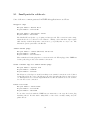
1
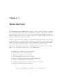
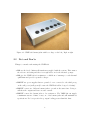
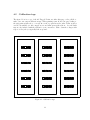
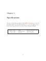
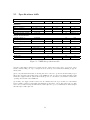
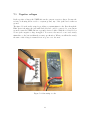
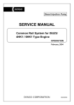
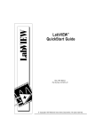
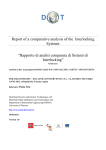
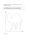
VREF-399 User Manual
Manual Revision (2010/01/15)
Board Revision C
Symmetric Research
www.symres.com
FREE WEB VERSION - PARTIAL CIRCUIT DIAGRAMS
Contents
1 Introduction
3
2 Getting started
2.1 Overview . . . . . . . . . . . . . . . . . . . . . . . . . . . . . . . . . . . . .
2.2 Do’s and Don’ts . . . . . . . . . . . . . . . . . . . . . . . . . . . . . . . . .
5
5
6
3 Theory of operation
3.1 Overall design . . . . . . . . . . . . . . . . . . . . . . . . . . . . . . . . . . .
3.2 Operating tolerances . . . . . . . . . . . . . . . . . . . . . . . . . . . . . . .
7
7
8
4 Calibration
4.1 Production calibration . . . . . . . . . . . . . . . . . . . . . . . . . . . . . .
4.2 Calibration tags . . . . . . . . . . . . . . . . . . . . . . . . . . . . . . . . . .
10
10
11
5 Specifications
5.1 Specifications table
5.2 Short term noise .
5.3 Long term noise . .
5.4 Thermal response .
12
13
14
15
16
.
.
.
.
.
.
.
.
.
.
.
.
.
.
.
.
.
.
.
.
.
.
.
.
.
.
.
.
.
.
.
.
.
.
.
.
.
.
.
.
.
.
.
.
.
.
.
.
.
.
.
.
.
.
.
.
.
.
.
.
.
.
.
.
.
.
.
.
.
.
.
.
.
.
.
.
.
.
.
.
.
.
.
.
.
.
.
.
.
.
.
.
.
.
.
.
.
.
.
.
.
.
.
.
.
.
.
.
.
.
.
.
.
.
.
.
.
.
.
.
.
.
.
.
.
.
.
.
6 Circuit Diagrams
7 Examples and Experiments
7.1 Connector options . . . .
7.2 Measuring the outputs . .
7.3 Negative voltages . . . . .
7.4 Potentiometer usage . . .
7.5 Differential applications .
7.6 A/D converter calibration
17
.
.
.
.
.
.
.
.
.
.
.
.
.
.
.
.
.
.
.
.
.
.
.
.
.
.
.
.
.
.
.
.
.
.
.
.
.
.
.
.
.
.
.
.
.
.
.
.
.
.
.
.
.
.
.
.
.
.
.
.
.
.
.
.
.
.
.
.
.
.
.
.
.
.
.
.
.
.
.
.
.
.
.
.
.
.
.
.
.
.
.
.
.
.
.
.
.
.
.
.
.
.
.
.
.
.
.
.
.
.
.
.
.
.
.
.
.
.
.
.
.
.
.
.
.
.
.
.
.
.
.
.
.
.
.
.
.
.
.
.
.
.
.
.
.
.
.
.
.
.
.
.
.
.
.
.
.
.
.
.
.
.
.
.
.
.
.
.
20
21
22
23
24
25
26
8 Frequently Asked Questions
27
9 Extra supplies
9.1 Small parts for cables etc . . . . . . . . . . . . . . . . . . . . . . . . . . . .
29
30
2
Chapter 1
Introduction
The Symmetric Research VREF-399 is a precision voltage reference suitable for general
lab use and applications such as the DC calibration of high resolution A/D converters.
The primary goal of the reference is to provide excellent long term stability with the same
voltages returned from one power on cycle to the next. No trim pots have been used to
avoid the stability problems they introduce.
Six fixed output voltages are available on individual banana jacks. Each of the voltages
is approximately one volt apart, with a calibration tag included for each system. The
reference as a whole is floating. Any one of the outputs may be taken as ground, with the
other outputs then distributed positive or negative from the grounded output.
The system only requires power from a wall transformer and connections to the reference
jacks for use. Among the leading features of the VREF-399 are:
•
LM399 heater stabilized buried zener design
•
Excellent short and long term stability
•
Six floating outputs in 1 volt increments
•
All outputs buffered with low noise op amps
•
Easy to use banana jacks for test leads and banana plugs
•
Perfect for calibrating 24 bit A/D systems
•
General lab usage includes potentiometer and sensor excitation
•
Test leads and wall transformer included
We hope the VREF-399 is a useful tool for your applications
3
Typical VREF-399 usage photo:
Figure 1.1: VREF-399 for A/D calibration
One popular VREF-399 application is for calibrating precision A/D converters.
In the photo above, the reference is connected to an SR USB4CH 24 bit A/D
system. With the reference voltages you can measure the counts per volt, and
with multiple jacks one volt apart you can also test linearity.
Because the reference is floating, generating a negative voltage is as easy as a
positive. Just reverse the leads. If grounding is necessary, simply connect any
one of the banana jacks to the desired ground. The other jacks are then
distributed positive and negative from the ground point.
Besides being used as a reference, the system can be used as an excitation
voltage for sensors like potentiometers. Each of the VREF-399 banana jacks is
capable of supplying 10ma of current while remaining within specifications. The
outputs are also tolerant of capacitive loads without oscillation.
4
Chapter 2
Getting started
The VREF-399 is easy to use. The following covers the steps.
2.1
Overview
Installation requires just plugging it in! The wall transformer should be plugged into
wall power and its 2.1mm plug into the back of the VREF-399. Use only 12 vdc 500ma
unregulated floating wall transformers as supplied with the system. Once plugged in, the
green LED on the top panel will light up showing power has been applied. After a short
warm up period, the VREF-399 is ready to use. Simply connect to any two banana jacks
to get a constant voltage. The size of the voltage depends on which two jacks are selected.
The further apart the jacks, the larger the constant voltage.
The VREF-399 is based on a National Semiconductor LM399 voltage reference. This
reference provides excellent long and short term stability by using a temperature controlled
buried zener. Usually the heater will stabilized in a minute or two, but a warm up period
of a half hour is best for the most precise results. The core LM399 reference voltage is
scaled and buffered to provide the output voltages on the 6 banana jacks. Each jack is
approximately 1 volt from the next.
Because the system is floating, you can designate any one jack as ground. Then all the
other jacks are measured relative to the jack taken as ground. For example, if banana jack
1 is taken as ground, then the voltage between jack 1 and 3 is +2 volts.
The Examples and Experiments chapter reviews several typical applications.
5
Figure 2.1: VREF-399 banana jacks with low voltage on the left / high on right
2.2
Do’s and Don’ts
Things to remember when using the VREF-399:
• DO use the 12vdc 500ma wall transformer supplied with the system. This ensures
the reference is floating and there is enough headroom for the internal op amps.
• DO give the VREF-399 a few minutes to a half hour of warm-up to reach thermal
equilibrium and provide repeatable voltages.
• DON’T use power supplies that are grounded or are connected to the third prong
on the wall power (wall ground) because the VREF-399 will no longer be floating!
• DON’T connect two different banana jacks to ground at the same time. Doing so
will short the outputs and draw excessive current.
• DON’T connect the banana jacks to low resistances. The VREF-399 can supply
a maximum current of 10ma on any one of its banana jacks and still maintain its
specifications. For best precision keep output loading greater than 100 ohms.
6
Chapter 3
Theory of operation
3.1
Overall design
The core of the VREF-399 is comprised of a precision LM399 reference followed by a resistor
ladder to generate multiple voltages. The LM399 is a lab grade semiconductor reference
with a nominal 7 volt output, and is generally thought of as one of the best semiconductor
references available. Its heater stabilized buried zener design guarantees the same voltage
from one power on cycle to the next. While other semiconductor reference technologies
such as bandgap references offer lower power consumption, they cannot match the LM399
for repeatable performance and stability without hysteresis.
Following the LM399 is a resistor ladder which generates the multiple core VREF-399
outputs which are further op amp buffered for the top panel banana jacks. The design first
reduces the LM399 output to 5 volts, and this is applied to a ladder of 5 equal resistors
to generate the 1 volt increments. Precision metal thin film resistors are used, with the
essential circuit shown in Figure 3.1 on the following page. The dark arrowheads represent
each output buffer and banana jack, and (V 1 . . . V 5) are the voltages between adjacent
pairs of jacks.
Note the circuit fragment does not show any ground connection. The VREF-399 is floating
and can be reference to any ground desired. Any single one of the banana jacks can
be connected to your system ground, and then the remaining jacks will be distributed
positive and negative from that ground referenced point. This allows for very flexible
usage depending on the application. The op amp output buffering can supply 10ma per
jack, isolating the core resistor ladder from user applications.
The design does not include any trim pots that could compromise thermal or long term
stability. The concept is to accept any initial tolerances, record the outputs, and then to
have their values be the same from one power on cycle to next in any thermal environment.
The advantages of this repeatability make avoiding the uncertainty of trim pots worth not
7
being trimmed to exactly 1 volt increments. A calibration tag is included with each system
reporting the banana jack voltages at the time of production. The initial tolerances and
the deviations from 1 volt increments are discussed in the next section.
Master reference = 5 volts ( +/-5%, 2ppm/C )
( floating LM399H )
R
R
R
R
R
V1
V2
V3
V4
V5
all R = 1K
( +/-0.05%, 10ppm/C )
Figure 3.1: VREF-399 output voltages
3.2
Operating tolerances
Although the core LM399 reference is extremely stable with respect to temperature and
time, its initial voltage tolerance is accurate only to within 5% across different parts. This
means the 5 volts shown across the resistor ladder in the circuit fragment above may vary
from 4.75 to 5.25 volts depending on the LM399 in your unit. Any given VREF-399 will
have a voltage somewhere in this range between its highest and lowest banana jack that
will not change with time or temperature.
Since the resistors in the ladder all have the same value, this also means the initial 5%
LM399 uncertainty will result in 0.95 to 1.05 volts between any pair of adjacent banana
jacks. This 5% initial overall tolerance is reported as Vjacks in the Specifications table, and
is the primary contribution to deviation from exactly 1 volt increments between the jacks.
A much smaller deviation from 1 volt increments is contributed by the tolerances of the
resistor ladder itself. Precision resistors with 0.05% initial tolerance are used. This means
8
the voltage between one adjacent pair of jacks to the next will be the same to within 0.05%.
For example, if the LM399 voltage across the resistor ladder was 5 volts, then the nominal
increments between the jacks would be exactly 1 volt assuming perfect resistors. Resistor
tolerances would affect this value from one adjacent pair of jacks to the next to be between
0.9995 and 1.0005 volts.
Once you determine the voltage between one pair of jacks, the value between other adjacent
pairs will deviate by at most 0.05% = 500 ppm or 500 microvolts. This variation in voltage
from one adjacent pair of jacks to the next is reported as ∆Vjacks in the Specifications
table. The exact voltages for a particular VREF-399 are reported on the calibration tag.
9
Chapter 4
Calibration
4.1
Production calibration
The VREF-399 is calibrated at the time of manufacturing. The calibration procedure is as
follows:
•
An HP34401A 6 digit voltmeter is used for voltage measurement
•
The VREF-399 is powered from a 12v 500ma wall transformer (110vac/60Hz)
•
Both the VREF-399 and HP34401A are given a one hour warm up period
•
Voltage measurements are then taken referenced from the lowest banana jack
•
The same measurements are taken with the HP34401A voltmeter leads reversed
•
Measurements are repeated three times at one hour intervals
•
Results are averaged and a calibration tag is then included with the system
No other record of the calibration is provided with the system. If you loose your calibration
tag, follow steps similar to the above to recalibrate the system. You may also wish to write
out custom tags for particular applications, measuring the voltages with respect to various
jacks grounded. Blank tags are on the following page. Symmetric Research also attempts
to keep calibration information for shipped systems on record. Contact us and we may be
able to help.
10
4.2
Calibration tags
The figure below is a copy of the file Tag.pdf. Print out either this page or the pdf file to
make your own custom calibration tags. When printing, turn off Acrobat page scaling so
the tags print at full scale to correctly fit on the top panel near the jacks. Print on index
card stock available at office supply stores and trim apart with scissors. Several blank
tags are also included with the system for your convenience. Write down the voltages with
respect to the jack you typically take as ground.
Figure 4.1: Calibration tags
11
Chapter 5
Specifications
The table on the following page lists the leading VREF-399 specifications. Several of the
performance parameters are also discussed in the Theory of operation chapter. A few of
the primary analog components used in the design are listed in the small table below.
Component specification sheets are also included with the distribution CDROM.
Voltage reference
Resistor ladder
Output opamps
=
=
=
LM399H
RG1608N-1.0K-W-T1
OPA2277UA
12
(National Semiconductor 5%)
(Susumu RG 0.05%)
(Texas Instruments)
5.1
Specifications table
Parameter
Comment
VREF-399 Specs
Min
Reference:
Vjacks
∆Vjacks variation
Noise floor
LM399 thermal stability
R ladder thermal stability
one pair to next
short term
long term
long term
Output characteristics:
Output current (1)
Voltage drop
Capacitive loading
maximum
10ma, 100 ohm load
without oscillation
Power supply:
Voltage (2)
Current
Current (3)
Warm-up time
0.95
Typ
Max
Units
1
0.05
1.05
5
2
10
V
%
µV
ppm per ◦ C
ppm per ◦ C
10
20
10
mA
µV
µF
30
200
Vdc
mA
mA
hour
70
◦
C
inches
0.3
14.7
initial turn on
operating
General:
Temp range
Dimensions
17
140
60
0.5
0
2.5 x 5
Figure 5.1: VREF-399 specifications table
(1) If more than 10ma is drawn from a banana jack, the output voltage may begin to drop and no longer
remain constant, falling out of spec. Outputs are short circuit protected with current limiting at approximately 35ma.
(2) Use only wall transformers that are floating and NOT connected to ground via the third wall prong as
this would compromise the floating nature of the VREF-399. Also note the 12vdc 500ma unregulated wall
transformer supplied with the system will normally provide 17 volts when loaded with the normal 60ma
operating current drain of the VREF-399.
(3) Normal power supply current is achieved about 2 minutes after the device is turned on. The LM399
heater normally consumes around 30mA and maintains a temperature of 90◦ C, almost the temp of boiling
water. At lower ambient temps the LM399 heater will require more power to maintain 90◦ C, while at higher
ambient temps it will require less.
13
5.2
Short term noise
Work underway . . .
short term noise plot
Figure 5.2: VREF-399 short term noise
14
5.3
Long term noise
Work underway . . .
long term noise plot
Figure 5.3: VREF-399 long term noise
15
5.4
Thermal response
Work underway . . .
thermal response plot
Figure 5.4: VREF-399 thermal response
16
Chapter 6
Circuit Diagrams
FREE WEB VERSION - PARTIAL CIRCUIT DIAGRAMS
This free web copy of the User Manual includes only the Circuit Overview and connector
assignments. Complete circuit diagrams are provided only with purchase of the product.
Install the CDROM that came with the product shipment for the full User Manual with
complete diagrams. Customers who need an update or have lost their original CDROM
may obtain copies of the full User Manual by emailing Symmetric Research.
Use the Adobe Acrobat reader View/Rotate View/Clockwise command to present the
diagrams horizontally on the screen.
Circuit Overview . . . . . . . . . . . . . . . . . . . . . . . . . . . . . . . . . . . . . . . . . . . . . . . . . . . . . . . . . . . . 18
Banana jacks . . . . . . . . . . . . . . . . . . . . . . . . . . . . . . . . . . . . . . . . . . . . . . . . . . . . . . . . . . . . . . . . 19
17
18
1
2
3
4
B
(100)
A
B
SERIAL NUMBER AND CALIBRATION STORAGE
FACTORY USE ONLY
SCHEMATIC PAGE 10
EEPROM
LINEAR REGULATION FOR LOW NOISE
2.1mm POWER CONNECTOR
(400)
12 VDC 500ma FLOATING WALL TRANSFORMER REQUIRED
SCHEMATIC PAGES 7-9
POWER SUPPLY
C
(900)
(200)
Title
Date:
Size
A
D
Wednesday, November 07, 2007
Sheet
Document Number
VREF-399.DSN, (c) Symmetric Research, 2007
01 OVERVIEW
FLOATING OUTPUTS
1
E
BANANA JACK FOR EACH OUTPUT
OUTPUTS IN 1 VOLT INCREMENTS
SCHEMATIC PAGE 6
6 OUTPUTS AVAILABLE
SCHEMATIC PAGES 3-5
E
LOW NOISE OPA2277 BUFFERS
OUTPUT CONNECTORS
D
LM399 WITH HEATER
OUTPUT BUFFERS
C
SCHEMATIC PAGE 2
PRECISION REFERENCE
SR VREF-399 BLOCK DIAGRAM OVERVIEW
A
of
10
(300)
Rev
C
1
2
3
4
19
1
2
3
4
B
A
J311
BRACKET FRONT PANEL
1
B
J310
BRACKET BACK PANEL
1
FROM OUTPUT BUFFERS
REFERENCE OUTPUT BANANA JACKS
A
VBREF0
VBREF1
VBREF2
VBREF3
VBREF4
VBREF5
C
C
1
1
1
1
1
1
J300
J301
J302
J303
J304
J305
BANANA JACK
BANANA JACK
BANANA JACK
BANANA JACK
BANANA JACK
BANANA JACK
Date:
Size
A
Title
D
Wednesday, November 07, 2007
Sheet
Document Number
VREF-399.DSN, (c) Symmetric Research, 2007
06 ANA OUTPUT CONNECTOR
ALL OUTPUTS FLOATING
VBREF0
VBREF1
VBREF2
VBREF3
VBREF4
VBREF5
D
6
E
E
of
10
Rev
C
1
2
3
4
Chapter 7
Examples and Experiments
The following are some examples of how to use the VREF-399:
.
Connector options
ways to connect to the banana jacks
.
Measuring the outputs
using a Fluke meter to measure the reference
.
Negative voltages
how to use the floating outputs
.
Potentiometer usage
providing excitation voltages for sensors
.
Differential applications
noise reduction with differential signals
.
A/D converter calibration
calibrating differential A/D inputs
20
7.1
Connector options
There are several ways to use the VREF-399 banana jacks. The best one to use depends on
the equipment you are working with. The following photos show some of the possibilities.
Figure 7.1: VREF-399 with banana plugs installed
Figure 7.2: VREF-399 with alligator leads installed
21
7.2
Measuring the outputs
The six constant voltages on the banana jacks range from 0 to 5 volts in increments of
approximately 1 volt. With no trim pots, the system has excellent long term stability. But
in return, the output voltages are not trimmed to integral values such as 3.00000 volts and
may have values such as 2.98786 volts. A measurement of the voltages is done at the time
of production, and the results are printed out on a calibration tag.
You can repeat the calibration yourself if you have access to a precision voltmeter. Meters
such as the Fluke 170 series are also acceptable for many applications. Uncertainty in the
initial absolute voltage at any banana jack is a different issue than the long term stability.
With the VREF-399 as its source, an A/D converter should return the same count results
each time a calibration is performed.
An example of measuring a positive voltage is shown in the following figure. In this setup,
a Fluke meter is used to measure the voltage between jacks 1 and 4. Since there are three
jacks between the red and black leads, the meter reads approximately 3 volts. The 2.988
volts shown is within the absolute VREF-399 specification.
Figure 7.3: Generating +3 volts
22
7.3
Negative voltages
Besides positive voltages, the VREF-399 can also generate negative voltages. Because the
reference is floating and not tied to a system ground, any of the jacks can be taken as
ground.
The figure below shows the setup for providing a constant minus 3 volts. Even though the
Fluke meter is floating, the jack with black test lead could be connected to your system
ground because the VREF-399 is not ground referenced either. With the red test lead on
a lower jack a negative voltage is supplied. You can see the meter does not read exactly
minus three volts, but is within the accuracy specification. What you will find is exactly
the same -2.988 voltage is returned from one power on to the next.
Figure 7.4: Generating -3 volts
23
7.4
Potentiometer usage
The VREF-399 can be used with a 10 turn potentiometer to generate small increments in
voltage for testing at low voltages.
Work underway . . .
24
7.5
Differential applications
The VREF-399 is perfect for use with systems having differential inputs. Differential connections are very effective techniques for dealing with ground loop currents and noise.
Work underway . . .
25
7.6
A/D converter calibration
The physical quantity intrinsically measured by most A/D systems is voltage, where a
corresponding digital count value is returned to the computer. Low input voltages return
a low count value, and as the voltage grows so does the count value.
The relationship between an input voltage and the output counts is referred to as the DC
Calibration of the A/D system, and is commonly modeled by a straight line with a slope
and offset. Determining the slope and offset of this line is the goal of calibration. Deviations
from a straight line characterize the nonlinearity of the system.
The VREF-399 can be used to perform A/D calibration by supplying several constant
voltages. For each voltage, acquire some data and then use the (voltage,count) pairs to fit
the best possible straight line. The resulting line will relate any particular output count to
an input voltage.
Because the VREF-399 is an independent stand alone reference, it provides an absolute
calibration standard. With its buried zener design and heated thermal stabilization, the
LM399 reference is considered one of the best semiconductor references available and will
provide repeatable measurements.
Work underway . . .
26
Chapter 8
Frequently Asked Questions
The following FAQ may help if you have general questions about the VREF-399.
What is a buried zener ?
Common zener diodes have their junction exposed to the surface of the silicon
substrate. For such diodes, surface currents and oxidation compromise the
short term noise and long term stability of the diode. Buried zeners place the
junction below the substrate surface to avoid these effects. The technique works
well, with buried zeners recognized as one of the best semiconductor reference
technologies available. The performance of a buried zener is further enhanced
when thermally stabilized as with the LM399.
What kind of power supplies can I use for the VREF-399 ?
Be sure to use a standard unregulated wall transformer that is connected to wall
power with only two prongs as is supplied with the system. If you use a power
supply that is grounded to the third prong on the wall socket, or other form of
system ground, then the VREF-399 will be referenced to that ground and no
longer be floating.
Can I really ground any of the six banana jacks ?
Yes. You can connect any one of the six banana jacks to your system ground.
The remaining jacks will then be at approximately 1 volt increments positive
and negative from the grounded jack. Do not ground more than one jack at a
time. Doing so shorts jacks together drawing excessive current.
27
I have lost my calibration tag, what can I do ?
The best approach is to re-measure the voltage at each jack and write a new
calibration tag. See the Calibration tags section for blank tags. SR attempts
to maintain calibration records. Contact us by email if you need help. The
product serial number will be required.
What affects voltage accuracy ?
For precise measurements at microvolt levels, the main culprit compromising
accuracy is voltage drops due to wiring. The feedback point for the op amps
driving the jacks is placed exactly at the banana jacks.
Drawing 10ma from a jack will not effect the voltage at the jack to within
specifications. However, if you connect to the jacks through long wires, and
then draw 10ma, the voltages at the ends of your wires will be off by the amount
dictated by Ohm’s law. In those cases, keep your wires short and draw as little
current as possible.
Typically 24 gauge stranded wire has a resistance of approximately 20 ohms
per 1000 feet. So, a one foot length with a resistance of 0.02 ohms and a
10ma current would have a V = IR = 0.0002 voltage drop. Depending on the
application, this may represent a significant error. Clearly with 100 feet of wire
the error becomes even larger.
For ease of use, the VREF-399 does not have separate Kelvin connections. The
Kelvin points are at the banana jacks, and voltages are maintained at those
points with the specified accuracy.
Besides voltage drops due to wiring, sometimes thermocouple effects between
metal junctions is a concern. One way to address such problems is to make
differential measurements and ensure the same number of thermocouples occur
in each side of the differential pair. See the Differential applications section.
Are the voltage increments between jacks exactly 1 volt ?
No. They are only approximately one volt apart, where approximately means
to within the specified absolute accuracy.
To avoid problems with long term drift, the VREF-399 does not have any trim
pots. The goal of the device is to provide the same voltages at the banana
jacks from one power on to the next over long periods of time. Use the production calibration info supplied with the system to scale A/D counts and similar
measurements into exact counts/volt etc.
28
Chapter 9
Extra supplies
Extra basic supplies such as cable and connectors may be required depending on the
VREF-399 application. SR can often provide such supplies on request, however many
customers may want to purchase such parts directly from suppliers themselves. This chapter lists a few typical parts and vendors. The list is only representative with many other
suppliers providing equally good products.
DigiKey
www.digikey.com
1(800)344-4539
Mouser Electronics
www.mouser.com
1(800)346-6873
JDR Microdevices
www.jdr.com
1(800)538-5000
Abbreviations used below:
MFG = Manufacturer
DK = DigiKey
MO = Mouser
JDR = JDR Microdevices
29
9.1
Small parts for cables etc
Some of the more common parts used in VREF-399 applications are as follows:
Alligator clips
MFG part number = Mueller BU-30
DK part number = 314-1010-ND
MFG part number = Silvertronic 501793
MO part number = 835-501793
The Mueller BU-30 clip has a good spring and strong teeth. The connection is wire crimp,
which should also be soldered for low resistance. Making cables with these clips requires
skill, but they result in inexpensive connections of good quality that are easy to use. The
Silvertronic part is equivalent to the Mueller.
Johnson banana plugs
MFG part number = Johnson (Emerson) 108-753-001
DK part number = J149-ND
MO part number = 530-108-0753-1
These uninsulated banana plugs have a 6-32 screw in the end. When plugged into VREF-399
banana jacks, they provide screw terminal connections.
Solder terminal lugs for Johnson banana plugs
MFG part number = Keystone 7329
DK part number = 7329K-ND
MO part number = 534-7329
The Keystone solder lugs are useful for making screw terminal connections to the Johnson
banana plugs. It is also easy to clip alligators onto these lugs when they have no wire soldered
on. The lugs listed above are flat. Lugs with internal tooth lock washer holes are also available
for even more secure connection.
Pomona test leads
MFG part number = Pomona 5519A
DK part number = 501-1004-ND
MO part number = 565-5519A
To use these test leads with the VREF-399 you must trim or cut away the banana plug
insulating shroud. Do this with a utility knife or razor blade carefully cutting away the
plastic shroud.
30
Twisted pair shielded cable
MFG part number = Belden 9501
MO part number = 566-9501-100
Twisted pair provides reasonable powerline noise immunity. This Belden cable also has a foil
shield and is jacketed. There are a large number of cable types available. The above is only
one example.
Potentiometers, 10 turn, 10K ohm
MFG part number = Vishay (Sfernice) 53411103
MO part number = 594-53411103
MFG part number = Bourns 3540 series
DK part number = 3540S-1-103-ND
A 10 turn pot is a simple and reasonably accurate sensor to use when testing the VREF-399.
There are many manufacturers of 10 turn pots. A 10K ohm unit will not draw excessive
current from the VREF output.
Wall transformers
MFG part number = Xicon
MO part number = 412-112054 (12vdc 500ma 2.1mm plug, 110vac input ** US)
Don’t use switching regulated wall transformers with the VREF-399. They will introduce
considerable high frequency noise into the system. Use only floating unregulated linear wall
transformer. Be sure to use a 12 volt 500ma unit. 9 volt units are not acceptable. Do not
daisy chain the wall transformer to other equipment creating unexpected ground connections.
2.1mm power plug
MFG part number = CUI Inc PP3-002A
DK part number = CP3-1000A
MFG part number = Kobiconn
MO part number = 1710-2131
These are discrete wire power plugs suitable for soldering wires to. They are useful for
connecting batteries and other custom power sources to the VREF-399. Use these instead of
chopping the plug off your wall transformer.
31
Batteries, 12 volt lead acid
MFG part number = BB Battery BP1.2-12-T1 (12v 1.2Ah)
DK part number = 522-1007-ND
MFG part number = Power Sonic (12v 1.4Ah)
MO part number = 547-PS-1212
These are small lead acid batteries. Running the VREF-399 from batteries may be of interest
for the ultimate in a floating reference. A 1.2 Ah battery would have enough power to run the
VREF-399 continuously for approximately 1.2/0.060 = 20 hours. Enough time to do some
reasonable work. Lead acid batteries are rechargeable.
32
Getting Technical Help
Answers to many general questions as well as resources such as application notes can be
found on our web site. If you have additional technical questions, please email us:
General product information: www.symres.com
SR technical help email address: [email protected]
33
Trees are green
Yakima, Washington, May 2006
VREF-399 User Manual
c , Symmetric Research, 2006, 2010
Copyright This material can only be reproduced in whole or part with the written permission of
Symmetric Research
No guarantee of suitability for any application is made with this document
All liabilities are the responsibility of the user
Email: [email protected]
Web: www.symres.com
34