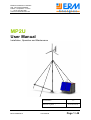
1
ERM Automatismes Industriels
280, rue Edouard Daladier
84200 – Carpentras – France
T : +33 (0) 490 600 568
www.erm-automatismes.com
MP2U
User Manual
Installation, Operation and Maintenance
Version :
Mise à jour :
MP2U 06/08/2012
User Manual
1.1
21/06/2012
Page 1 / 48
ERM Automatismes Industriels
280, rue Edouard Daladier
84200 – Carpentras – France
T : +33 (0) 490 600 568
www.erm-automatismes.com
Index
Safety First! ................................................................................................................ 3
Warning! ..................................................................................................................... 3
Introduction ................................................................................................................. 4
Operation .................................................................................................................... 5
Scope of delivery ........................................................................................................ 7
Trainer lockable steel box ........................................................................................... 8
List of needed tools .................................................................................................... 9
Installation .................................................................................................................. 9
Unloading the trailer ................................................................................................ 9
Installation of the PV generator ............................................................................. 14
Installation of the wind turbine............................................................................... 17
Tower Assembly ................................................................................................ 17
Raising the tower ............................................................................................... 21
Installing the wind turbine .................................................................................. 25
Installation of the load ........................................................................................... 27
Commissioning ..................................................................................................... 28
Mise en service ..................................................................................................... 28
Connecting the PV modules and the wind turbine ............................................. 28
Grounding.......................................................................................................... 28
Turning on the MP2U ........................................................................................ 28
Modes................................................................................................................ 29
Man-Machine Interface ...................................................................................... 30
Alarms ............................................................................................................... 38
Variables ........................................................................................................... 39
Data Logging ..................................................................................................... 40
Last check before going ........................................................................................ 40
GSM/GPRS Test ................................................................................................... 40
Service and Maintenance ......................................................................................... 40
Preventive maintenance........................................................................................ 40
Electrical maintenance ...................................................................................... 40
Fuse replacement .............................................................................................. 42
Wind turbine Specifications ............................................................................... 43
Inspection and maintenance ................................................................................. 44
Failure analysis ......................................................................................................... 45
Failure identification on MP2U .............................................................................. 45
Failure identification on wind turbine ..................................................................... 45
MP2U Technical Specifications ................................................................................ 46
MP2U 06/08/2012
User Manual
Page 2 / 48
ERM Automatismes Industriels
280, rue Edouard Daladier
84200 – Carpentras – France
T : +33 (0) 490 600 568
www.erm-automatismes.com
Safety First!
Warning!
Reading this manual and dutyfully following its prescriptions are compulsory in order
to run properly and safely the MP2U.
Take your time to read it carefully and never go to the operation site without it.
Installation, operation, service and maintenance of a MP2U unit shall expose you to
various risks. These risks are described below. They are marked in the manual with
the corresponding icons. Be careful!
1. Electric shocks: Teh MP2U system is based on a nominal DC voltage of 24V.
There are therfore limited risks of electrocution except the leads between the
petrol generator and the battery charger. These leads are properly isolated.
: This symbol will be used at the proper place in the manual to show
when there might be an electric hazard.
2. Physical risks: The design of the MP2U involves heavy metal parts with hinges
and lifting action. It can induce injuries if not handled properly. It is vital to
follow this manual’s instructions and to use the proper tools the proper way to
avoid any problem. Individual safety equipment to be used will be adverted at
the proper installation steps with the following icons :
: Safety shoes compulsory
: Gloves compulsory
: Helmet compulsory
3. Environmental risks: The MP2U involves many components and some of them
might induce some specific environmental risks. This risks are highlighted with
the following icons:
: Fire risk, inflammable material
MP2U 06/08/2012
User Manual
Page 3 / 48
ERM Automatismes Industriels
280, rue Edouard Daladier
84200 – Carpentras – France
T : +33 (0) 490 600 568
www.erm-automatismes.com
: High temperature, risk of getting burned.
: Battery risks (high currents in case of short circuit, acid…)
4. Embedded signs in the MP2U: Signs on the MP2U placed at proper locations
will highlight local risks. They should be carefully taken into account when
using the MP2U. Take care that every people interacting with the MP2U has
read this manual and has his safety equipment on him.
5. Operators of the MP2U: Only properly trained and qualified staff is allowed to
interact with the MP2U. This system is complex and requires specific skills.
Important
ERM Automatismes has made all possible efforts to make sure that all
information included in this manual are updated but ERM Automatismes shall
not be responsible for any mistake or ommission. The users of this manual
shall bear the entire responsibility of the use of their MP2U and of the
corresponding risks. ERM Automatismes will not endorse any responsibility in
case of any prescription of this manual not being met by the user and if the
user’s inconsequence is obvious.
This manual does not replace any of the manuals provided with the various
manufactured equipment included in the MP2U.
Introduction
This manual includes all the information needed to run the MP2U dc 400/1/700-24
It relies to all MP2U dc systems.
These systems are designed to provide secured power to remote appliances using
local renewable energy sources (sun, wind…).
They are built to last in the « Heavy Metal School » style and in accordance with
Eurocode 1, NV65 and CM66 standards and can withstand winds up to 42 m/s.
The system’s schematic is as follows:
Several energy providers (small wind turbine, PV, petrol genset) will charge a Li-ion
battery bank. A DC load will be fed by this battery bank.
MP2U 06/08/2012
User Manual
Page 4 / 48
ERM Automatismes Industriels
280, rue Edouard Daladier
84200 – Carpentras – France
T : +33 (0) 490 600 568
www.erm-automatismes.com
Operation
The wind turbine and the photovoltaïcs will charge the battery using the local
available resources (sun and wind). These resources are fluctuant and consequently,
the battery state of charge evolves with time.
When the batteries are full, controllers will reduce the charging.
When the batteries are empty, the charger starts and allows the batteries to be
charged by the petrol generator.
A PLC records the parameters of the system (currents, voltages, temperatures…)
drives the various components.
This PLC also deals with the GSM/GPRS/3G/Ethernet communication and will
automatically send alarm SMS to the people in charge. The phones numbers are set
by the user at first installation.
It is also used as an anti-hijack system.
MP2U 06/08/2012
User Manual
Page 5 / 48
ERM Automatismes Industriels
280, rue Edouard Daladier
84200 – Carpentras – France
T : +33 (0) 490 600 568
www.erm-automatismes.com
The MP2U relies on local natural resources. It was at first designed to be able to feed
a 150W permanent load in the Highlands in Northern Scotland. Depending on the
site, PV or wind shall have different contributions to the energy production. Tropical
areas will most of the time depend mainly on sun but when latitude increases, wind
will have a more important part to play.
The map below indicates the areas where the MP2U should be suitable for you if you
want to feed à 100W permanent load or less. Of course, local environment has to be
considered and every site will have its own capacities. Please make sure that, when
installing the MP2U, real care is taken to have the PV modules as exposed to sun as
possible and at the right pitch angle, and that the wind turbine is properly set out of
turbulences and at the windiest place possible.
MP2U 06/08/2012
User Manual
Page 6 / 48
ERM Automatismes Industriels
280, rue Edouard Daladier
84200 – Carpentras – France
T : +33 (0) 490 600 568
www.erm-automatismes.com
Scope of delivery
The MP2U is delivered as one single closed unit. It can be delivered on request with
the EasyLow© system and a trailer. Scope of delivery is as follows:
Item
MP2U main enclosure
Yingli 235Wc PV Module
E300 small wind turbine including
Blade set (3 blades)
Tail
Tail boom
Alternator + pitch control system
Nosecone
Screws and bolts
20m power cable
Battery li-ion 3,6V 700Ah
Battery charger Victron Centaur 1200VA
PLC including
Touchscreen box
Emergency stop box
Measurements box
Power box
Terminals box
PLC Back Up battery sealed 12V 40Ah
Genset 3300W Hyundai
Cable puller 1600kg
Cable for cable puller 20ml
Handle for cable puller
Sandows
GSM/GPRS external antenna
Enclosure adjustable feet
MP2U 06/08/2012
Unit
Quantity
U
Ens
U
U
U
U
U
Lot
Ens
U
U
Ens
U
U
U
U
U
U
U
U
U
U
U
U
U
2
1
3
1
1
1
1
1
20ml
8
1
1
1
1
1
1
1
2
1
1
1
1
2
1
4
User Manual
Page 7 / 48
ERM Automatismes Industriels
280, rue Edouard Daladier
84200 – Carpentras – France
T : +33 (0) 490 600 568
www.erm-automatismes.com
Item
Pads
Tower tubes junctions
Keys
Compartment under the enclosure
Tubular tower for wind turbine
Tube
Baseplate
Gin pole head
Tower head
Guy set
Anchors
Turnbuckles, shackles, cable-clips and accessories
Trailer + EasyLow©
Stand gusset
Stand foot
Lockable steel box
Electrical plus to connect trailer to car
Unit
U
U
U
Quantity
4
8
1
Ens
U
U
U
U
Lot
U
Lot
1
6
1
1
1
1
8
1
U
U
Ens
U
2
4
1
1
Trainer lockable steel box
Chain hoists
Stand top carter
Adjustable straps
Bolts and nuts
Ens
U
U
U
Lot
1
4
4
4
1
The overall weight of the MP2U is 1 041 kg including:
Steel enclosure
Steel floor
E300 wind turbine
8m tower
Anchors
Power cable
PV modules
PV stand
Batteries
Genset
Supporting steel board for
electronics
Victron Centaur charger
Controls
Fuse box
Tool box
Enclosure main gate
Total
en kg
320
24
75
150
10
10
40
7
168
32
15
18
7
2
67
96
1 041
This weight does not include the trailer.
MP2U 06/08/2012
User Manual
Page 8 / 48
ERM Automatismes Industriels
280, rue Edouard Daladier
84200 – Carpentras – France
T : +33 (0) 490 600 568
www.erm-automatismes.com
List of needed tools
Compass
Spirit Level
Torque wrench (20 to 60Nm)
Open-end wrenches set (8 à 30mm)
Ratchet and sockets (8 à 30 mm)
Electric powered wrench
Adjustable wrench 15" ou 18"
Combination pliers
Strong pliers
Steel wire
Heavy hammer 8kg
Rope or line level
Spray paint
Standard electrician tool box
Grommet for electric cables
Voltmeter DC
Ampmeter DC
Installation
Unloading the trailer
Purpose of the step:
The MP2U must be set in a place as flat and cleared as possible (maximum slope is 8%).
Take into consideration that you will have to install the MP2U but also the wind turbine and
that the wind turbine should not be shading the PV modules. Remember that the turbine has
to tilt up and down easilty (see step 4.2.1 Tower rising).
Tools needed for this step:
- Spirit Level, open end wrenches: 16-17-24, Ratchet and sockets: 16-17-24
MP2U 06/08/2012
User Manual
Page 9 / 48
ERM Automatismes Industriels
280, rue Edouard Daladier
84200 – Carpentras – France
T : +33 (0) 490 600 568
www.erm-automatismes.com
Step / Description
1/ Positioning the trailer:
The trailer has to be oriented so that
the PV modules will be facing South
in the Northern hemisphere, and
North in the Southern hemisphere.
The main door will be facing the
other way.
Picture
Picture shows proper orientation for
Northern hemisphere.
2/ Preparing the EasyLow©
system:
Fit the stand feet in the stand
gusset, taking care to have the feet’s
plates horizontal. Secure with an
M16 bolt.
3/ Unloading stand tubes:
Open the steel hood and pull out the
two tubes having fixing lugs.
MP2U 06/08/2012
User Manual
Page 10 / 48
ERM Automatismes Industriels
280, rue Edouard Daladier
84200 – Carpentras – France
T : +33 (0) 490 600 568
www.erm-automatismes.com
4/ Finalizing the stands:
-Prepare the stand feet by having
them on both sides of the trailer.
-Put a tube on the two stands taking
care to have the fixing lugs
downwards.
-once properly adjusted, secure with
the top carter and four bolts.
MP2U 06/08/2012
User Manual
Page 11 / 48
ERM Automatismes Industriels
280, rue Edouard Daladier
84200 – Carpentras – France
T : +33 (0) 490 600 568
www.erm-automatismes.com
5/ stand adjustment :
-Make sure the stand is stable
-Mov the stand in order to make sure
that the trailer will be able to move
both ways.
-Stand tube should be about 20cm
far from the MP2U enclosure.
-Adjust horizontality using a spirit
level and modifying the feet length
using the optional holes.
This should be done at both ends of
the MP2U.
6/ Installing the hoists
-Attach the hoists to the fixing lugs
on the tube and to the corresponding
fixing lugs on the MP2U. The hoist
should stay close to the tube while
using the hoist (use the chain hook
to connect to the MP2U).
MP2U 06/08/2012
User Manual
Page 12 / 48
ERM Automatismes Industriels
280, rue Edouard Daladier
84200 – Carpentras – France
T : +33 (0) 490 600 568
www.erm-automatismes.com
7/ Removing the trailer
-Use the hoists to lift the MP2U a
few cm above the trailer floor.
-pull the trailer out manually.
8/ Bringing the MP2U down:
-Use the hoists to bring the MP2U
down slowly.
Be careful to keep the MP2U
horizontal during the process to
prevent any dangerous swing.
Once the MP2U is about 30m above
the ground,
-adjust horizontality using the hoists,
-put the pads in place beneath the
MP2U feet,
-unlock the feet (they have to slip
down to the pads),
-fit the small bent bar into the
nearest holes under the MP2U. Do
not use the holes they were already
fitted in for transport.
MP2U 06/08/2012
User Manual
Page 13 / 48
ERM Automatismes Industriels
280, rue Edouard Daladier
84200 – Carpentras – France
T : +33 (0) 490 600 568
www.erm-automatismes.com
The MP2U is now on the ground.
Release the hoists and dismount
the stands.
Open the MP2U and find next
components inside.
Installation of the PV generator
Purpose of the step:
The PV modules will be put in place in a way nobody can dismount them once the MP2U is
closed. Be careful to be two to carry the modules, especially when wind is blowing.
Needed tools for this step:
Open end wrench: 16-17
Ratchet and sockets: 16-17
Step / Description
1/ Electric cables:
-open the eyelet by rotating it and
push the cables through.
-close the eyelet.
MP2U 06/08/2012
Picture
User Manual
Page 14 / 48
ERM Automatismes Industriels
280, rue Edouard Daladier
84200 – Carpentras – France
T : +33 (0) 490 600 568
www.erm-automatismes.com
2/ Installing the modules
-put the two modules in place
slipping the lugs in the slots.
They should be hanging without
being held.
3/ locking the top fixation:
-insert the 12mm stainless steel bar
through the top of the MP2U passing
through the modules’ lugs.
-check from inside the MP2U that
the bar is properly put in place. It
has to be fully inside the enclosure
(not protruding end).
-lock with the safety pin.
4/ Installing the down fixation:
-Insert the Ø 21.3mm bar in the
bottom lugs of the modules.
The two modules are now
assembled.
-Fit the plastic caps at both ends of
the bar.
-hang the offset arms to the bar, in
front of the slots in the MP2U wall.
There are two offset arms sets: one
for 60° module slope and another for
45°. Chose the angle nearest to the
latitude of the site plus 10°.
MP2U 06/08/2012
User Manual
Page 15 / 48
ERM Automatismes Industriels
280, rue Edouard Daladier
84200 – Carpentras – France
T : +33 (0) 490 600 568
www.erm-automatismes.com
5/ locking of the PV generator
-Swing the modules up slowly. Lift
the offset arms and slip them
through the slots in the MP2U wall.
- Secure the offset arms from the
inside using the M10 bolts.
MP2U 06/08/2012
User Manual
Page 16 / 48
ERM Automatismes Industriels
280, rue Edouard Daladier
84200 – Carpentras – France
T : +33 (0) 490 600 568
www.erm-automatismes.com
The PV generator is now installed
and secured.
Installation of the wind turbine
Tower Assembly
Purpose of this step:
The tower is made of 4 tubes linked together by steel bolt shells. Be careful in siting the
anchors properly. This will ease any later servicing a lot.
Needed tools for this step:
Flat spanner, open end wrenches 10-13-16-17
Sockets 10-13-16-17
Hand held screwing machine
Adjustable pliers
Strong pliers
Steel wire
Step / Description
1/ Overview:
Picture
-4 anchors for guys. The Winch
Anchor is the one considered as the
operating point.
-A baseplate on which the tower
rests.
MP2U 06/08/2012
User Manual
Page 17 / 48
ERM Automatismes Industriels
280, rue Edouard Daladier
84200 – Carpentras – France
T : +33 (0) 490 600 568
www.erm-automatismes.com
2/ Siting:
-Nail the baseplate to the ground
using the steel rods provided.
-Draw two lines at right angle
meeting in their middles.
Tilt side
-Place the right and left anchors
15cm ahead of the moving towards
the front anchor.
-Mark on the ground the places of
the anchors.
3/ Anchors
For the right, the left and the front
anchor: nail 2 galvanized steel posts
one behind the other at 50° +-10° and
50 +-10 cm apart on the marks made
previously.
(The post the closest to the
baseplate is the reference. It has to
be nailed on the mark. The second
one is placed behind and will be
used to support the front one. The
fixing rings must be facing towards
the baseplate. Thelowest ring has to
be not more than 10cm above the
ground).
- The winch anchor is made of two
reference posts (one for the cable
puller and one for the guy) and a
third securing post placed behind.
- Put the steel slings in place
between the two posts….
Notice: This anchoring method is the most versatile
one ERM Automatismes could design but still, it
might not be adequate for specific grounds (sand,
wet area, rocky sites…) and it is the installer’s
responsibility to choose another way to make the
anchors when needed.
Maximum load in the guy, if the installation has been
done as prescribed in this manual, is 575 DaN. This
value is correct for both tilting and extreme winds.
MP2U 06/08/2012
User Manual
Page 18 / 48
ERM Automatismes Industriels
280, rue Edouard Daladier
84200 – Carpentras – France
T : +33 (0) 490 600 568
www.erm-automatismes.com
4/ Positioning the tubes
-The tubes are marked. Align them
on the ground starting from the
baseplate in the correct order 1, 2, 3
and 4.
- Fit the tube 1 into the baseplate.
Use the M20 bolt as a shaft to attach
the tube to the holes closest to the
front anchor.
5/ Tower assembly:
-Put together two shells using 8 M10
bolts kept loose. Fit an M10 bolt in
the middle hole and tighten it. It will
be used as an end stop.
-Fit the shell assembly over the tube
1 up to the end stop.
-Slip tube 2 into the shell assembly.
Make sure the tubes are aligned and
are both pushed in up to the stop.
-Tighten all bolts progressively.
-Proceed the same way for tubes 2
and 3 and 4.
-Fit the two smaller shells (used to
hold the guy plate at teh right height
on the tower) oveer the 4th tube.
They should be placed so that they
are 1,50m far from the tower top.
-Slip the guy plate over the fourthe
tube until it rests on the small shell
assembly.
MP2U 06/08/2012
Guys are
attached
here
User Manual
Page 19 / 48
ERM Automatismes Industriels
280, rue Edouard Daladier
84200 – Carpentras – France
T : +33 (0) 490 600 568
www.erm-automatismes.com
5/ Assembling the ginpole:
-Fit the ginpole together as you did
for the tower. It comes on the upper
holes in the baseplate.
- Fit the ginpole head on top of the
second tube, insert the M20 treaded
bar in the holes protruding and
through the fixing plate and secure
with the two red rings.
Ginpole head
6/ Guys:
Basic rules for guys buckles:
-A cable clamp has to be put in a
specific way. The wide part has to
be on the active string and the U
part on the dead end. “Never put a
saddle on a dead horse” is the
rule.
-The spacing between two cable
clamps is 10 times the diameter of
the cable e.g. for this 10mm cable,
the minimum spacing is 10cm.
U part
Saddle
-Attach the front guy to the guy plate
under the tower with a shackle and
the other end of the guy to the front
anchor.
- For each lateral guy, follow the
same process, inserting a shackle
between the guy and the turnbuckle.
-Attach the winch guy to the top hole
of the guy plate and the other end to
the ginpole head, on the one holed
side of the plate.
Secure all the shackles with iron
wire to prevent them from
unscrewing.
MP2U 06/08/2012
User Manual
Page 20 / 48
ERM Automatismes Industriels
280, rue Edouard Daladier
84200 – Carpentras – France
T : +33 (0) 490 600 568
www.erm-automatismes.com
7/ Ginpole guys:
-Attache the ginpole guys to the red
rings on the ginpole head and to the
shackles on the lateral anchors.
8/ Installing the cable-puller:
-Attach the cable puller to the winch
anchor with two 1,5t shackles.
-Attach the hook to the ginpole head
using a 1,5t shackle in one of the
two available holes of the plate. Slip
the cable inside the cable-puller.
Raising the tower
Needed tools for this step:
-Spirit level
-Adjustable wrench 16" ou 18" (to adjust turnbuckles)
Caution: tilting up the tower must be completed in proper weather
conditions. Wind should be below 6 m/s and there should not be any
chance of lightning strikes.
In case of equipment failure or human mistake, consecuencies are immediate
and cannot be anticipated. It is therefore compulsory to tilt the tower with as
little people as possible in the danger area (anywhere the tower might fall).
Nobody should be standing within the square made by the anchors. The staff
dealing with the process of tilting the tower must wear individual safety
equipments as requested by the law and must have been properly trained. If it
is a public site, a danger zone area should be fenced using red tape.
MP2U 06/08/2012
User Manual
Page 21 / 48
ERM Automatismes Industriels
280, rue Edouard Daladier
84200 – Carpentras – France
T : +33 (0) 490 600 568
www.erm-automatismes.com
Common rules:
-
Never use force when it is not supposed to be used. Is something gets stuck,
try to understand why.
-
The tower and the ginpole must be under control in all the directions during all
the process. They should not be allowed to move anywhere without being
allowed to.
-
During the process avoid having people changing places.
-
The operator in charge of the cable-puller is the one in charge of the tilting
process. He has to monitor and follow up what his colleagues are doing and
should give orders when needed.
-
At least two people are needed to tilt the tower up / down. The cable-puller
operator and the one in charge of checking the lateral guys’ tension. When the
latter moves from one lateral anchor to the other, he should always pass
behind the cable-puller operator in order to keep out of the danger area.
-
Only approved and trained technicians should be in the area. Please ask
anybody else to move apart.
-
The operating staff must have their tools with them and should not have to
move around to look for them during the process.
-
The site must be cleared.
If a problem arises during the tilting process, the tower has to be put back
down in a safety position before the problem gets solved and rised again.
Never try to solve a problem working under a partially tilted tower.
Before starting the tilting procedure, chek thoroughly all the guys, shackles,
turnbuckles, anchors to be sure that everything has been fitted / tightened
properly.
ALWAYS RAISE THE TOWER WITHOUT THE TURBINE FIRST
1/ Things to check:
-Front guy in place.
-Cable-puller properly attached and
easy to operate.
-Guys are free to move their ways,
nothing is in their way.
-Guys do not cross each other.
MP2U 06/08/2012
User Manual
Page 22 / 48
ERM Automatismes Industriels
280, rue Edouard Daladier
84200 – Carpentras – France
T : +33 (0) 490 600 568
www.erm-automatismes.com
2/ Raising the ginpole
-One person will lift the ginpole
carrying it at its head to ease the use
of the cable-puller at starting.
-The ginpole has to be kept straight
and should not bend to the right or
left. Adjust the ginpole guys
accordingly.
3/ Installing the holding rope:
When the tower is about to be
vertical, the weight of the ginpole will
pull the tower towards the cablepuller operator. To keep this phase
under control, a rope is attached to
the front guy with a shackle and kept
tensioned by a staff member.
4/ tower raising:
-The cable-puller is operated and the
tower slowly tilts up. Keep the
ginpole vertical and the tower head
aligned with the base plate and the
winch anchor.
-Tensions of the lateral guys have to
be checked permanently.
MP2U 06/08/2012
User Manual
Page 23 / 48
ERM Automatismes Industriels
280, rue Edouard Daladier
84200 – Carpentras – France
T : +33 (0) 490 600 568
www.erm-automatismes.com
5/ Adjusting the guys:
-The ginpole guys usually get tense
when raising the tower. They have to
be loosened progressively.
-The tower guys will also get tense
and will have to be adjusted at the
first rising. Once this has been done
once, they should not have to be
adjusted anymore. Yet they have to
be checked at every operation on
the tower.
6/ Holding the tower:
At the end of the tilting process, the
weight of the ginpole will pull the
tower up. To keep the tower under
control, an operator bends the front
guy with the holding rope and will
release slowly the rope to make the
tower come to its final position
slowly.
7/ Remowing the cable-puller:
Once the tower is raised, put in
place the sling between the anchor
and the last hole of the plate.
Tension it using the turnbuckle until
the cable puller can be safely
removed.
The ginpole can also be removed if
needed.
MP2U 06/08/2012
User Manual
Page 24 / 48
ERM Automatismes Industriels
280, rue Edouard Daladier
84200 – Carpentras – France
T : +33 (0) 490 600 568
www.erm-automatismes.com
8/ Verticality:
-Adjust the guys in order to have the
tower perfectly vertical and straight
from bottom to top.
-Once it has been done, secure the
turnbuckles slipping the dead end of
the guys throught them and through
the shackles. This will prevent the
turnbuckles from unscrewing
themselves because of vibrations.
The guys must be holding the tower
but not pulling it down. Do not
tighten too much the turnbuckle. The
guy must be loose enough to “wave”
when you shake it.
9/ Tilting down:
-Install the cable-puller
-Pull the tower with the holding rope
-Remowe the sling
Carry on the reverse process.
Installing the wind turbine
Things to know:
This step is described in the wind turbine manual
Needed tools for this step:
Open end wrenches: 10-13-19
Sockets: 10-13-19
Torque wrench
MP2U 06/08/2012
User Manual
Page 25 / 48
ERM Automatismes Industriels
280, rue Edouard Daladier
84200 – Carpentras – France
T : +33 (0) 490 600 568
www.erm-automatismes.com
Step / Description
1/ Power cable:
-Slip the power cable connected to
the turbine inside the tower.
Picture
2/ Pivot flange:
-Insert the cable protecting tube
inside the tower.
-Remove the holding screws and
detach the tube from the turbine.
-Bolt the flanges together with the
M8 screws with the torque wrench at
35Nm (25.8lb.ft)
3/ Fitting the tail
-fit the tail to the tail boom using the
M6 bolts tightened at 20Nm (15lb ft)
Note that the GFP carter is not used.
This differs from the turbine manual.
MP2U 06/08/2012
User Manual
Page 26 / 48
ERM Automatismes Industriels
280, rue Edouard Daladier
84200 – Carpentras – France
T : +33 (0) 490 600 568
www.erm-automatismes.com
4/ Assembling blades
-Fit the blades to the hub as
specified in the turbine manual.
-Tighten the M12 bolts at 50Nm
(37lb ft)
5/ Fitting the nose cone:
-Slip the nose cone over the
protruding studs.
-Tighten cautiously the M6 nuts at
4Nm (3lb ft)
6/ Final tilt up:
-Follow previous steps from “Raising
the tower” page 21.
Installation of the load
To install the load, e.g. your Lidar, please refer to the manufacturer’s manual.
MP2U 06/08/2012
User Manual
Page 27 / 48
ERM Automatismes Industriels
280, rue Edouard Daladier
84200 – Carpentras – France
T : +33 (0) 490 600 568
www.erm-automatismes.com
Commissioning
Before proceeding to the starting procedure, check the following points:
- PV is properly oriented.
- Tower is straight and guys secured.
- Easy opening of the doors. If the MP2U is not resting evenly on its 4 legs, it might
get slightly bent and make the doors opening difficult.
Mise en service
Connecting the PV modules and the wind turbine
All the connections are made in the terminal box. PV
cables are already in place with MC4 terminals and can
be connected to the modules. Please follow the color
code.
Wind turbine cable has to be connected to the two
biggest terminals in the box.
Grounding
All the appliances in the MP2U are grounded via the steel enclosure. The enclosure
itself has to be grounded using the post provided.
The wind turbine tower is also linked to the MP2U common earthing using the
specific cable provided.
Turning on the MP2U
Upon starting, the main door is open. All switches are on the OFF position.
Power up the PLC by pushing in the F7 fuse (See page Erreur ! Signet non défini.
“Erreur ! Source du renvoi introuvable.”). The PLC starts and puts itself in
STANDBY mode. In this mode, the wind turbine is shorted, the PV is off, the Genset
is off.
Once the system has been commissioned, the power up is done using the red
switches:
There are four of them:
- An emergency push button to disconnect the main batteries (« Batteries »),
- A rotating switch that shorts the wind turbine and therefore stops it in low and
medium winds (« WT Brake »). See “Erreur ! Source du renvoi introuvable.” page
Erreur ! Signet non défini..
- A rotating switch interrupting all RE sources, PV and wind (« RE Power »)
- A rotating switch opening the Genset/charger DC circuit.
MP2U 06/08/2012
User Manual
Page 28 / 48
ERM Automatismes Industriels
280, rue Edouard Daladier
84200 – Carpentras – France
T : +33 (0) 490 600 568
www.erm-automatismes.com
Initial position: everything is stopped.
A steel carter forces a sequence. All rotating handles should be put upwards before
the push button is activated. This carter should always be down in its normal position
when running the system.
On the touch screen, a keyboard appears for the input of the code. If the code is valid
(Default code is 1873), The START screen comes up. By cliking on START, the user
starts the system and goes to mode RUN. The STOP button comes up.
If the user closes the door of the enclosure, he can still open it within 5 minutes
without using the code. If he delays more than 5 minutes, he will have to input the
access code again otherwise the anti-hijack alarm will get active.
Remark:
During services, the user opens the door and has a 2 minute delay to input the
access code until the alarm comes up. He can then access the STOP button. He can
either stop the system (and put it back in STANDBY mode by pushing the STOP
button) or he can access the various screens of the software (Wind Turbine, PV, GE,
Load…). If he manually stops a component, the mode will turn to DEGRADED. The
user must leave the DEGRADED mode to get back to RUN mode manually by
putting everything back into operation.
Modes
As specified previously, there re 3 modes:
The STANDBY mode
This is the mode which is active before starting the system, when the PLC has just
been turned on.
The system is also put in this mode when the STOP button is pushed.
MP2U 06/08/2012
User Manual
Page 29 / 48
ERM Automatismes Industriels
280, rue Edouard Daladier
84200 – Carpentras – France
T : +33 (0) 490 600 568
www.erm-automatismes.com
The RUN mode
It is the normal operating mode. It is active as soon as the user pushes the START
button. In this mode, the PLC is in charge of everything and drives the RE sources
according to the various inputs measured.
The DEGRADED mode
This is the maintenance mode. The user automatically switches to it when he
manually forces the system to do the following actions:
1 – Braking the wind turbine
When the BRAKE button is pushed, the DEGRADED mode turns on. The BRAKE
has to be released for the mode to return to RUN.
2 – Stopping the PV
When the “Turn PV off” button is pushed, the mode is set to DEGRADED. When it is
released, it comes back to RUN.
3 – Starting / stopping the Genset
The mode does not automatically switches to DEGRADED for the Genset as it can
be started manually anytime. The user has to push the AUTO/MAN button to change
modes and can only START/STOP the genset using the appropriate button when in
mode MAN (=DEGRADED).
4 – Start / stop Load
Exemple given here is for the ZephIR Lidar but works for any appliance. When the
“Stop the ZephIR” button is pushed, the mode switches to DEGRADED and comes
back to RUN when released.
Man-Machine Interface
When the PLC is powered up, a keybord screen appears for the access code. Once
the code is input, the starting screen comes up.
Access code keyboard. Factory set code is 1873.
MP2U 06/08/2012
User Manual
Page 30 / 48
ERM Automatismes Industriels
280, rue Edouard Daladier
84200 – Carpentras – France
T : +33 (0) 490 600 568
www.erm-automatismes.com
Starting screen
Press the START button to run the MP2U.
The buttons in the left bottom corner of thescreen (Mode: AUTO/MANU and the small
flag next to it) show in which state the system is. To be in the RUN mode, the AUTO
label has to be on. As long as it is on MANU, the PLC is in DEGRADED mode and
this means a forced action is on. Check all the screens to release the relevant
buttons.
The small square flag turns red when an alarm message is active. You can access
the last message generated by clicking on it.
Alarm screen
MP2U 06/08/2012
User Manual
Page 31 / 48
ERM Automatismes Industriels
280, rue Edouard Daladier
84200 – Carpentras – France
T : +33 (0) 490 600 568
www.erm-automatismes.com
All components of the system can be accessed by touching them. Touch the wind
turbine to go to the wind turbine screen.
Wind Turbine screen
Going back to previous screen is done pushing the blue arrow on the top left of the
screen. This is true for all screens.
This screen, as for other energy sources, gives a lot of indications about the output of
the turbine. It also includes a brake button. If this button is pushed, the turbine will be
directly connected to the dump load and will therefore slowly come to a stop. It might
not stop quickly depending on how strong the winds are but i twill not feed the
batteries anymore and is in a safe position. It can be let this way for days if needed.
Spread values are the following:
Time off: number of times since the turbine has been producing power.
Electric Brake: this flag indicates if the turbine is fully connected to the dump load or
not.
Power/Wind: instant usable power fed to the batteries by the wind turbine (power
sent to the dump load is not measured).
Instant Amps: Instant amps sent to the batteries. As a reminder, the battery bank is
in 28.8V.
Max Amps: Maximum current measured sinc the system has been started.
Ave Pow 24h: Average power for the last 24 hours. This value is set to 0 when
starting the system and up to 24 hours after.
Max Pow 24h: Maximum power recorded within the last 24 hours. This value is set to
0 when starting the system and up to 24 hours after.
E_1day: last day energy output. Reset to 0 when the system is started.
E_7days: last week energy output. Reset to 0 when the system is started.
E_total: Total energy produced by the wind turbine since the system has been
started.
If the MP2U enclosure is touched on the staring screen, the Enclosure screen is
reached:
MP2U 06/08/2012
User Manual
Page 32 / 48
ERM Automatismes Industriels
280, rue Edouard Daladier
84200 – Carpentras – France
T : +33 (0) 490 600 568
www.erm-automatismes.com
Enclosure screen
The blue components are the Controls. The green one is the Genset, The orange
ones are the batteries and the Lidar and the PV modules can also be accessed by
touching them.
PV Screen
The PV screen displays the same kind of parameters as what is read on the wind
turbine screen. The “Turn PV OFF” button stops the production.
Genset screen
MP2U 06/08/2012
User Manual
Page 33 / 48
ERM Automatismes Industriels
280, rue Edouard Daladier
84200 – Carpentras – France
T : +33 (0) 490 600 568
www.erm-automatismes.com
The Genset screen allows to manually start/stop the Genset.
Notice: the Genset can only be started if its key is switched to the ON position
allowing the starter to be fed by the Genset battery. This allows to keep the Genset
stopped during maintenance and to prevent any unwished starting. The Genset
battery is kept charged by the MP2U.
The flag at the top right angle shows the charging state of the Genset. It is reading
« Genset ON » when the Victron Centaur charger is actually charging the batteries. If
the Genset is disconnected from the charger, it might be running but not charging the
batteries. In this case, the flag reads “Genset OFF”.
The Genset beng the less reliable device of the MP2U, it has a specific management
program. When batteries are low and the outputs of the wind turbine and the PV
generator are too low to feed the load, the Genset is automatically started. If the
starting fails (lack of oil, lack of petrol, any other reason…), the PLC tries to restart
the Genset three times. If all these attempts fail, it sends an alarm SMS.
If the Genset failed 4 times, the PLC will not try to start it until the “Clear Failed
Starts” button has been manually pushed by the maintenance staff.
It is possible that the MP2U is delivered with another Genset than the one illustrated
on the screen. In any case, please refer to the Genset manual for operation and
maintenance.
There is no petrol level indicator in the Genset tank. But there is a counter indicating
the numbers of times it has been running. We suggest the user to reset this counter
each time the tank is filled. This counter is not taken into account in the management
system so it can be forgotten without any consecuencies.
The load also has a specific screen:
Load Screen
MP2U 06/08/2012
User Manual
Page 34 / 48
ERM Automatismes Industriels
280, rue Edouard Daladier
84200 – Carpentras – France
T : +33 (0) 490 600 568
www.erm-automatismes.com
It is possible to stop feeding the load by pushing the « Turn ZEPHIR OFF » button.
When the load is not working (because it has been switched off or because it is not
drawing power), a “Not working” flag appears.
Controls can be accessed by touching the blue components on the enclosure screen.
Controls screen
This screen gives information about the working state of the Controls but does not
allow any action. Apart for transportation / long storage reasons, the PLC has to be
functional permanently to protect the components of the system.
A GSM/GPRS button allows reaching the Modem screen:
Modem screen
This screen allows checking the quality of the GSM/GPRS signal. Pushing the
Settings button leads to the setting of phone numbers to dial for the SMS alarms.
MP2U 06/08/2012
User Manual
Page 35 / 48
ERM Automatismes Industriels
280, rue Edouard Daladier
84200 – Carpentras – France
T : +33 (0) 490 600 568
www.erm-automatismes.com
The phone numbers can be changed by pushing the appropriate button. A keyboard
pops up and the number can be dialed.
Once the phone number has been set, a test message can be sent using the button
next to the target number. It is therefore possible for the phone owner to be sure that
he will receive the alarm SMS.
The User will only receive major alarms. The Maintenance 1 and 2 will receive every
alarm. See page Erreur ! Signet non défini. “Erreur ! Source du renvoi
introuvable.”
Phone numbers keyboard
Next screen can be reached by touching the orange components on the Enclosure
screen.
MP2U 06/08/2012
User Manual
Page 36 / 48
ERM Automatismes Industriels
280, rue Edouard Daladier
84200 – Carpentras – France
T : +33 (0) 490 600 568
www.erm-automatismes.com
Battery screen
Batteries should never be put out of order but for emergency reasons using the
manual red push button. This screen is only giving information which is:
SOC: State Of Charge indicating the energy available in the batteries. A 100% value
means the batteries are full. Warning: this value is not perfectly exact. There is an
uncertainty of +/- 5% approx as it is calculated dynamically but this uncertainty will
remain constant in time, which is not the case of most available SOC calculators.
Voltage: main battery bank voltage.
Half battery voltage: This voltage is used to compare the voltage of 4 batteries out
of 8 in the bank. It allows knowing if one battery in the bank is having a defect. If this
is the case, the system is immediately stopped and an alarm SMS is sent. Defect in
batteries can lead to fire with Li-ion batteries and have to be taken into account as
soon as they arise.
Battery temperature: a temperature probe is measuring the battery temperature. If
the temperature gest too high (more than 60°C), the system is stopped until the
temperature comes down to 40°C.
Inside temperature: enclosure inside temperature
Outside temperature: a probe is fitted outside the enclosure to compare the outside
and inside temperatures.
The GRAPH button allows reaching the following screen:
GRAPH screen
MP2U 06/08/2012
User Manual
Page 37 / 48
ERM Automatismes Industriels
280, rue Edouard Daladier
84200 – Carpentras – France
T : +33 (0) 490 600 568
www.erm-automatismes.com
The GRAPH screen displays the main power values of the system every second. The
graph function can be started / stopped. To go back to previous screen, push the
ESC button.
Alarms
The PLS sends various alarm SMS. All the SMS come with the date, time and SOC
(State Of Charge).
The SMS are only sent once when the problem arises.
The table below lists down all the alarms:
P
CONDITION
ACTION
MESSAGE
The anti-hijack lead (PV, Turbine and Door) has been
opened.
Automatic action : none
Manual action : find reason of the opening
1 MESSAGE (Date + time + 'Problem in battery A battery cell is deffective
unit' + SoC)
Automatic action : system stopped
Manual action : battery control
2 MESSAGE (Date + time + 'Zephir default' +
Load current is zero (<IZEP_MIN)
SoC)
Automatic action : none
Manual action : check the load
3 MESSAGE (Date + time + 'Low battery, power Battery voltage is too low (<=UBAT_MIN2)
supply default' + SoC)
Automatic action : system stopped
Manual action : check availability of power sources (PV,
Turbine, Genset)
4 MESSAGE (Date + time + 'High battery
High battery temperature (>=TBAT_MAX)
temperature' + SoC)
Automatic action : power sources stopped
Manual action : battery control
5 MESSAGE (Date + time + 'Hot temperature
High temperature inside encllosure (>=TINT_MAX)
inside power supply system' + SoC)
Automatic action : none
Manual action : check enclosure fan
6 MESSAGE (Date + time + 'Modem battery
Back up battery voltage low (<=UBAUX_MIN)
default' + SoC)
Automatic action : none
Manual action : check that back up battery are properly
charged by system
7 MESSAGE (Date + time + 'Low battery, petrol Battery voltage is low (<=UBAT_MIN1) and the power
generator on' + SoC)
sources do not produce enough to cover the load
Automatic action : Genset starting
Manual action : none
8 MESSAGE (Date + time + 'Low gasoline' +
Time of use of Genset > TGE_MAX
SoC)
Automatic action : none
Manual action : fill up Genset petrol tank
9 MESSAGE (Date + time + 'Solar panel default' Current out of the PV generator is zero during TPV_KO
+ SoC)
Automatic action : none
Manual action : check the PV generator
10 MESSAGE (Date + time + 'Wind turbine
Current ouot of the wind turbine is zero during TEOL_KO
default' + SoC)
Automatic action : none
Manual action : check the wind turbine
11 MESSAGE (Date + time + 'Parafoudre default' Digital input 1 is 1
+ SoC)
Automatic action : none
Manual action : replace faulty surge arrestor
12 MESSAGE (Date + time + 'Relai statique PV
Call ERM Automatismes
KO' + SoC)
0
MESSAGE (Date + time + 'Possible intrusion'
+ SoC)
MP2U 06/08/2012
User Manual
Page 38 / 48
ERM Automatismes Industriels
280, rue Edouard Daladier
84200 – Carpentras – France
T : +33 (0) 490 600 568
www.erm-automatismes.com
P
CONDITION
ACTION
MESSAGE
13 MESSAGE (Date + time + ' Relai statique
débordement KO ' + SoC)
14 MESSAGE (Date + time + ‘Chargeur Victron
KO ou panne d’essence' + SoC)
Call ERM Automatismes
15 MESSAGE (Date + time + ‘Passage en mode
Run')
16 MESSAGE (Date + time + ‘Passage en mode
Standby’+ SoC)
17 MESSAGE (Date + time + ‘Passage en mode
dégradé’+ SoC)
Charger not charging.
Automatic action : none
Manual action : check Genset
System in RUN mode
System in MANUAL mode
System in DEGRADED mode
An SMS is sent when an alarm arises. As long as the alarm is still active, no further
SMS is sent. The alarm has to be cleared and to rise again for a new SMS to be sent.
There are 3 users with a linked priority:
P1, highest level, only major alarms – Labeled « User » on screen
P2, medium level, all alarms, most of the time, this number is kept for ERM
Automatismes – Labeled « Maintenance1 » on screen
P3, local level, for field satff, all alarms – Labeled « Maintenance2 » on screen
Variables
Inputs
The PLC measures and records the following parameters.
INPUT
TYPE
TAG
DESIGNATION
1_AI1
1_AI3
1_AI5
1_AI7
1_AI9
1_AI11
1_AI13
1_AI15
2_AI1
2_AI3
2_AI5678
2_AI9101112
2_AI13141516
DI1
DI2
ANALOGIC INPUT
ANALOGIC INPUT
ANALOGIC INPUT
ANALOGIC INPUT
ANALOGIC INPUT
ANALOGIC INPUT
ANALOGIC INPUT
ANALOGIC INPUT
ANALOGIC INPUT
ANALOGIC INPUT
ANALOGIC INPUT
ANALOGIC INPUT
ANALOGIC INPUT
DIGITAL INPUT
DIGITAL INPUT
U_2BAT
U_BAT
U_BAUX
I_BAT
I_PV
I_EOL
I_GE
I_CONS
I_COMM
I_DEBOR
T_BAT
T_INT
T_EXT
E_PAR
E_INT
TENSION 1/2 BATT
TENSION BATTERIE
TENSION BATT AUX
COURANT BATTERIE
COURANT PV
COURANT EOLIENNE
COURANT CHARGEUR GE
COURANT 28V
COURANT AUX
COURANT DEBORDEMENT
TEMP BATT
TEMP INT
TEMP EXT
FUSION PF
INTRUSION
MP2U 06/08/2012
User Manual
Page 39 / 48
ERM Automatismes Industriels
280, rue Edouard Daladier
84200 – Carpentras – France
T : +33 (0) 490 600 568
www.erm-automatismes.com
Ouputs
The PLC drives the following outputs:
OUTPUT TYPE
TAG
DESIGNATION
DO1
DIGITAL OUTPUT
SSR1
DO2
DIGITAL OUTPUT
SSR2
DO3
DIGITAL OUTPUT
K1
DO4
DIGITAL OUTPUT
SSR3
DO5
DO6
DO7
DIGITAL OUTPUT
DIGITAL OUTPUT
DIGITAL OUTPUT
SSR4
K3
K4
RELAI STATIQUE PV
RELAI STATIQUE EOLIENNE
PWM
RELAI COMMANDE K2 RELAI
DEBORDEMENT
RELAI STATIQUE
DEBORDEMENT PWM
RELAI STATIQUE ALIM
LIDAR
VALIDATION GE
MARCHE GE
Data Logging
Every second, data is stored in a buffer. Every 10 min, the average of these 600
values is calculated and stored on the SD card as a csv file. The SD card can be
removed at any time to read the data. As soon as it is in its slot, the PLC is logging.
When no SD card is in the slot, no logging is done.
Last check before going
Once the system has been put into operation, spend a few minutes having a look at
each screen and check the various parameters. If something seems unusual, do not
hesitate to call ERM Autmatismes +33 (0) 490 600 568 for explanations.
GSM/GPRS Test
It is useful to check that SMS are properly sent. On very remote sites, the networks
might be weak and might need a bigger external antenna that can be fitted on the
turbine tower. Call ERM Automatismes for details.
Service and Maintenance
Preventive maintenance
The preventive maintenance should be performed at each deployment, as well as at
alarm induced intervention. If no alarm is received, preventive maintenance should
be performed once a year.
Electrical maintenance
Before any action on the system, measurements have to be done:
MP2U 06/08/2012
User Manual
Page 40 / 48
ERM Automatismes Industriels
280, rue Edouard Daladier
84200 – Carpentras – France
T : +33 (0) 490 600 568
www.erm-automatismes.com
Measurements
Check U voltages for:
- The wind turbine (0 < U < 150VDC) in the terminal box
- PV Generator (0 < U < 36VDC) in the terminal box
- Battery bank (22 < U < 32VDC) on the battery lugs
- Back up batteries (18 < U < 28.8VDC) on the battery lugs
- Charger (22 < U < 32VDC) on the DC output lugs at the bottom of the charger
Putting the installation out of service
Turn everything of before working on the electrical components:
- Switch all red rotating handles in a vertical position.
- Wait for the turbine to stop
- Push the red battery button
Reminder: Despite these actions, DC voltages are still present in some parts
of the system (batteries, PV modules).
Battery bank
Reminder: The opposite terminals of a battery bank (+ and -) should never be
short circuited. Consecuencies will always lead to heavy damages and
might cause serious injuries.
- Clean the battery bank with a dry cloth
- Check corrosion on the battery lugs
- Check the proper tightening of the screws
- Measure voltage « U » for each battery (2.8 < U < 4Vcc)
- Measure voltage « U » for the whole bank (22 < U < 32Vcc)
- Look for any physical defect: leaks, swollen battery, damages of any kind.
Warning: Li-ion batteries fires must be extinguished with the proper fire
extinguisher provided. If not available, use water.
PV Generator
Reminder: PV produces voltage as soon as exposed to light.
- Measure open circuit voltage « Uoc » out of the PV generator (0 < U < 36Vcc
depending on sunlight)
- Clean PV modules with a clean cloth. Water and glass soap can be used.
Controls
Reminder: The PLC is fed by back up batteries and therefore, DC voltages
are still present in the boxes.
- Clean the insides of the boxes with a dry clean cloth. Check for insects or
rodents.
- Check for evidences of overheating (smell, dark traces…)
- Check the tightening of every terminal
MP2U 06/08/2012
User Manual
Page 41 / 48
ERM Automatismes Industriels
280, rue Edouard Daladier
84200 – Carpentras – France
T : +33 (0) 490 600 568
www.erm-automatismes.com
Fuse replacement
Pictue below shows the power fuses in their enclosure.
MP2U 06/08/2012
User Manual
Page 42 / 48
ERM Automatismes Industriels
280, rue Edouard Daladier
84200 – Carpentras – France
T : +33 (0) 490 600 568
www.erm-automatismes.com
Wind turbine Specifications
Design
Speed control
Nominal power
Diameter
Swept Area
Starting wind speed
Cut in wind speed
Nominal wind speed
Blade material
Rotating speed
Alternator
Voltage output
Number of poles
Tower top weight
Max Lateral thrust
3 bladed upwind rotor
Centrifugal pitch control
1
3
7
2.5
3
12
GFRP
0 to 800
Permanent magnet, drect drive
24
12
75
200
kW
m
m²
m/s
m/s
m/s
RPM
VDC
kg
DaN
System description
Alternator
Rotor
Nacelle
Tail boom
Yaw shaft
Tails
MP2U 06/08/2012
User Manual
Page 43 / 48
ERM Automatismes Industriels
280, rue Edouard Daladier
84200 – Carpentras – France
T : +33 (0) 490 600 568
www.erm-automatismes.com
The e300iii is a unique wind turbine that incorporates superior technology. The heart
of the machine comprises of a unique twin axial flux permanent magnet brushless
alternator. The alternator contains no less than 96 poles and 52 magnets. The
polyphase high frequency output is internally rectified to give a dc output with
extremely low ripple content. The generated power is transferred to the output cables
via heavy duty bronze slip rings and twin copper composite electrical brushes. The
prime mover on the e300iii is a 3.0m (9.85’) diameter three blade wind rotor fitted
with quiet running high efficiency blades. The blade hub incorporates passive pitch
control. The e300iii pitch control changes the operating angle of the blades to
achieve speed control in high wind. The tail vane assembly is static and simply aligns
the machine with the prevailing wind.
All steel components are electro-galvanised and passivated for extra protection. The
standard finish consists of the application of an etching marine primer and an
intermediate protective coat followed by polyurethane two pack finishing coats.
Inspection and maintenance
As a standard rule, the pitch control system should never be modified. It has been set
in factory with specific tools and any modification would void the warranty.
Frequency
Item
Duty
Comments
As often as you
can
Every six
months of
operation
Wind
Turbine
Tower
Check for abnormal
noises or vibrations.
Check that the guys are
properly tensioned and in
good state.
Check for corrosion and
losened bolts
Visual inspection of the
blades.
Check for loosened
bearings in the alternator
or in the yaw shaft
Look for rust on the
nacelle or on the
alternator
If so, check the whole turbine and look for
the cause.
Only for ERM Towers. If you use your
own tower, rely on the manufacturer’s
recomandations.
Use galvanised and color car paint for
corrosion. Tighten loose bolts. Call ERM
Automatismes is blades are damaged.
Wind
Turbine
Eolienne
Once a year
Wind
Turbine
Tower
MP2U 06/08/2012
Check the slip ring
assembly. Check the wear
of the pitch control
system.
Check all the cable
clamps, shackles and
turnbuckles.
Check the top of the tower
and all the bolts involved.
User Manual
This needs the tower to be tilted down.
Replace faulty spares and correct other
problems as previously.
Only for ERM Towers. If you use your
own tower, rely on the manufacturer’s
recomandations.
Page 44 / 48
ERM Automatismes Industriels
280, rue Edouard Daladier
84200 – Carpentras – France
T : +33 (0) 490 600 568
www.erm-automatismes.com
Failure analysis
Failure identification on MP2U
Most of the problems are delat with by the PLC. It is most of the time possible to
understand a problem thanks to the screens. Other possible failures are listed below:
Problem
Possible reasons
Remedy
Load is not
powered anymore
Load fuse out of
order
Batteries are too low
Batteries are at risk
(high temperature or
faulty cell)
PLC is out of order
Replace F9 fuse. See “Fuse
replacement” page 42.
Check the Genset tank
Check every battery cell and find the
overheating source.
PV Generator
does not produce
PV Fuse out of order
Batteries are full
Not enough light.
Moduleq are in the
shade.
Modules are dirty.
Modules are not
facing the sun.
No voltage in the
terminal box
Battery voltage
rises too much
(more than 36V)
PLC reports hijack
all the time
Static relays out of
order
Alarm lead cut.
Poor door contact
Replace F7 fuse. Call ERM
Automatismes if problem remains.
replace F2 fuse. See “Fuse replacement”
page 42
Normal operation
No breakdown. Correct problem.
One of the modules’cable has been
damaged or cut. One of the MC4
connectors is loose or disconnected.
Check electric circuit.
Check SSR2 and SSR3 relay. See
Electrical drawings.
Check the continuity of the alarm lead in
the terminal box. Look for a discontinuity.
Check door contacts.
Failure identification on wind turbine
Problem
Possible Reasons
Remedy
Wind turbine is
not spinning at
all, even in high
winds
Mechanical problem on
the turbine. Broken
alternator, faulty bearing,
foreign object interfering.
Call ERM Automatismes
MP2U 06/08/2012
User Manual
Page 45 / 48
ERM Automatismes Industriels
280, rue Edouard Daladier
84200 – Carpentras – France
T : +33 (0) 490 600 568
www.erm-automatismes.com
Problem
Wind turbine
spins very
slowly, even in
high winds
Low output
Wind turbine
vibrates
Wind turbine
does not face
wind
Wind turbine
spins very fast
but does not
produce
Possible Reasons
Short circuit on the turbine
leads
Remedy
Find the short circuit. Check the
relays, the diodes and the cable.
Worn bearings
Replace bearings.
Surge arrestor out of order Replace surge arrestor
and grounding a turbine
lead
Low wind
Poor turbine siting. Change siting or
increase tower height (Call
ERMAutomatismes for optional higher
towers)
Rotor unbalanced
Check the blades and the pitch
control system. Blades should be
120° apart and all have the same
weight and same gravity center.
Tower is not vertical
Correct verticality
Yaw shaft bearing worn
out
Cables disconnected
Replace yaw shaft bearing.
Check cables
Slip ring assembly broken
Check slip ring assembly.
MP2U Technical Specifications
Device
Main Batteries
Emergency
Batteries
Wind Turbine
MP2U 06/08/2012
Specifications
Type : LYP700 Li-Yttrium
Capacity : 700Ah – cell voltage : 3.2Vdc
8 cells = bank voltage 25.6Vdc
Max voltage allowed : 32Vdc
Min voltage allowed : 22,4Vdc
Dim : 627 x 67 x 306 mm – Weight : 21kg + /- 300g per unit
Type : SGP12-40 Powerline
Capacity : 40Ah C20 – cell voltage : 12Vdc
2 cells = bank voltage 24Vdc
Max voltage allowed : 28.8Vcc
Min voltage allowed : 18V
Dim : 250 x 180 x 190 mm – Weight : 7,2kg per unit
Type : Kestrel e300 – Diam. 3m 1000W@12m/s
User Manual
Page 46 / 48
ERM Automatismes Industriels
280, rue Edouard Daladier
84200 – Carpentras – France
T : +33 (0) 490 600 568
www.erm-automatismes.com
Device
PV Modules
Genset
Charger
PLC
MP2U 06/08/2012
Specifications
Rated RPM : 650
Max voltage : 150Vdc open circuit full speed
MPPT voltage : 30Vdc
Axial flux permanent magnet alternator
Pitch control – 3 blades
Weight : 40kg
IP55 – IEC61400-2
Tower : Guyed tubular tower tiltable 8m – galvanised steel
Type : YL 235 P-29b-1
Power output : 235.0 W +/- 3%
Efficiency : 14.4%
Voltage at Pmax (MPPT) : 29.5Vdc
Current at Pmax (MPPT) : 7.97A
Open Circuit Voltage : 37.0V
Short Circuit Current : 8.54A
NOCT : 46 +/- 2 °C – T° coeff. Gamma of P : -0.0045/K
Dim : 1650 x 990 x 50 – Weight : 19.8kg
IP65 – MC4 connectors IP67
Design Wind Load : 2.4KPa
Gasoline generator Type DFD3000H
Output voltage : 230V 50Hz
Nominal Power : 2.5kW – Max Power – 2.8kW
4 stroke engine 6.5HP 3600RPM 196cm3
Air Cooling
Fuel tank capacity : 15 litres (approx 5 times at full load)
Noise level : 69dB(A)
Fitted in skid – Weight : 46kg
CE marked
Type : Centaur Victron 24/80
Input Voltage Range : 90 – 265Vac or 90-400Vdc
Frequency : 45 – 65Hz - cos Phi = 1
Absorption Voltage : 28.5Vdc
Float Voltage : 27Vdc – 3 outputs
Charge current : 80A – Analogical Ammeter
3 steps charging – internal temperature sensor
Fan cooling – short circuit protection included
Working temperature : -20°C to 60°C
Ignition Protected – IP21
Dim : 505 x 255 x 230mm – Weight : 16kg
EN60335-1, EN60335-2-29, UL1236, EN55014-1, EN61000-3-2,
EN55014-2, EN61000-3-3
Type : XV102 Eaton Moeller
Screen Diagonal/Type : 3.5’’ TFT-LCD Color QVGA 320x240
LED Backlight
Processor : RISC, 32-bit, 400MHz
DRAM 64Mby – NVRAM 32Kby – SD Memory card slot
User Manual
Page 47 / 48
ERM Automatismes Industriels
280, rue Edouard Daladier
84200 – Carpentras – France
T : +33 (0) 490 600 568
www.erm-automatismes.com
Device
KPS Enclosure
Specifications
Ethernet – CANOPEN
Webserver
Power supply : max 5W – 24Vdc
Hot dip Galvanised Steel fully lockable
Dim. :
Weight : 1250kg
For any other information: Call ERM Automatismes.
Your comments:
___________________________________________________________________
___________________________________________________________________
___________________________________________________________________
___________________________________________________________________
___________________________________________________________________
___________________________________________________________________
___________________________________________________________________
___________________________________________________________________
___________________________________________________________________
___________________________________________________________________
___________________________________________________________________
___________________________________________________________________
___________________________________________________________________
MP2U 06/08/2012
User Manual
Page 48 / 48