1
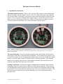
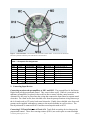
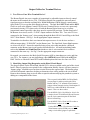
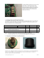
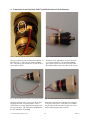
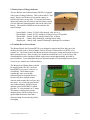
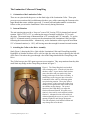
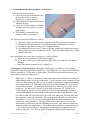
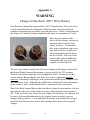
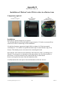
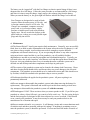
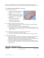
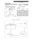
Boston Digital Arm-Plus System Clinical Manual This manual provides guidance on the LTI Boston Digital Arm System for the Prosthetist and Prosthetic Technician. The system should be set up and adjusted by a qualified clinician. The following instructions will help guide the clinician to obtain the optimal performance for the user and allow them to achieve maximum functionality and reliability. Revised 02/06/12 Liberating Technologies, Inc. 325 Hopping Brook Road, suite A 508-893-6363 Holliston, MA 01746-1456 Fax 508-893-9966 www.liberatingtech.com CONTENTS 1. Input Connector Board 1 Organization of the Board 2 Connecting Input Devices 3 Removing Connectors 4 Sealing the Input Board 5 Adding the Cover Board 6 The Most Popular Configurations 2. The Forearm 1 The Forearm Attachment 2 Cutting the Forearm to Length 3 Colors and Wrist Diameters 3. Output for Terminal Devices 1 Two-Wire or Four-Wire Terminal Device 2 Identifying Plug Receptacles 3 Selecting Cables for TD or Wrist Rotator 4 Connections to Wrist Rotators 4. Battery & Charging 1 Battery (Lithium-polymer upgrade) 2 Battery Installation & Removal 3 Battery Charger 4 Battery Charging 5 Battery State of Charge Indicator 6 Terminal Device Power Board 5. Lamination Collar 1 Orientation of the Lamination Collar 2 Internal Rotation 3 Attaching the Collar to the Drive Assembly 4 Orienting the Lamination Collar 5 Limit Stops 6 Final Adjustment with the User 6. Troubleshooting & Repair 1 Maintenance 2 Troubleshooting 3 Connector Repair Appendix A – Otto Bock Wrist Rotator Appendix B – Motion Control Wrist Rotator 7. © Liberating Technologies, Inc. 2011 User Manual (Clinician’s copy) 2 02/06/12 The Input Connector Board 1. Organization of the Board The standard input connector. Figure 1 shows the top of the connectors used to attach input cables to the Input Connector Board. A three or four-wire ribbon cable enters each connector. The first wire (darker in this photo) is the positive power connection and the second wire is the negative. Thus, if you place a plug unto the wrong receptacle, you may not generate a signal where you need it, but no harm will be done. Finally, no matter where you plug in, the wires will always point toward the hole in the center of the Input Connector Board. Figure 1. Making connections to the Input Connector Board. On the left you can read the labels MY1 and MY2. On the right, the connectors from the preamplifiers are passed up through the rubber seal and pushed in place. The wires block further view of the labels. The connection points. There are nine plug receptacles on the Input Board with short labels. Study Figure 2 and Table 1 where the labels are identified. Two receptacles are primarily used for myoelectric inputs, two are for proportional analog signals, two are for on-off digital signals, and two are used to connect motors for shoulder locks or vibratory feedback. The remaining connector is for passing a pair of extra or spare signals around the elbow and all the way to a connector on the distal end of the main circuit board. Labeling of connectors. On all but the simplest configurations of a Boston Arm System, the connecting cables to the Input Connector Board are labeled during assembly. This means that you can unplug the various connectors to route wires without fear of forgetting where the plugs go afterward. If you need to undo the connectors, check first to be sure labels are in place. The discussion below is mainly for users who are planning to try several configurations with a particular client. © Liberating Technologies, Inc. 2011 3 02/06/12 Figure 2. Connection labels. The labels here are those used in Table1 below. In most cases the cables that attach to a particular connection point will also have the same label. Table 1. Receptacle Pin Assignments Label MY1 MY2 A12 A34 D12 D34 MC MD X12 Pin 1 + 5.0V + 5.0V + 5.0V + 5.0V + 5.0V + 5.0V (+12V)* (+12V)* + 5.0V Pin 2 0.0V Ground 0.0V Ground 0.0V Ground 0.0V Ground 0.0V Ground 0.0V Ground 0.0V Ground 0.0V Ground Remote On Pin 3 Analog 5 Analog 6 Analog 1 Analog 3 Digital 1 Digital 3 Motor C1 Motor D1 Extra 1 Pin4 Myo Input 1 Myo Input 2 Analog 2 Analog 4 Digital 2 Digital 4 Motor C2 Motor D2 Extra 2 Purpose myoelectric input #1 myoelectric input #2 analog inputs 1&2 analog inputs 3&4 digital inputs 1&2 digital inputs 3&4 output to motor C output to motor D to XTR on circuit board * 12V here only if requested 2. Connecting Input Devices Connecting myoelectrode preamplifiers to MY1 and MY2. The preamplifiers for the Boston Digital Arm provide proportional control. They come in three styles. When it is convenient, the miniature preamplifiers are placed in the socket in direct contact with the control muscles. Alternatively, they may be placed into the wiring that connects the Input Board to separate metal electrodes. For a hard socket, three shielded wires from the preamp terminate in lugs that accept the 4-40 studs used on LTI cavity-back metal electrodes. Finally, three shielded wires from each preamp can be supplied with snaps to connect to the metal electrodes in a roll-on sleeve. The first myoelectrode is connected to MY1 and the second myoelectrode to MY2. Connecting LTI Touch Pads to A12 and A34. Touch Pads are analog devices that provide proportional control. These force-sensing resistors (FSR’s) are used in pairs to control multiple © Liberating Technologies, Inc. 2011 4 02/06/12 devices or singly to activate a device selection scheme or to operate a force-sensitive servo. With more than two pads, the first pair is connected to A12 and the second pair to A34 using a BE341 Cable, Two Touch Pad Plugs. Often a pair of Touch Pads connected to A12 will operate the terminal device, while a single pad connected to A34 with a BE340 Cable, One Touch Pad Plug will operate the elbow by using a force servo. Touch Pads must be mounted in a certain way. (See Input Devices, Touch Pads.) These sensors are almost exclusively used with frame sockets for shoulder disarticulation patients. (See Chapter Frame sockets for use with Touch Pads.) Connecting the LTI Linear Transducer to A34 for servo operation. The positional servo is a popular control choice for the transhumeral amputee because the biceps and triceps muscles are left free to control the terminal device myoelectrically, while the servo independently controls the elbow. The BE235 Linear Transducer is an analog device and is connected to A34. The transducer may also be used to as a source of variable voltage to operate other devices. It is usually connected to A34 whenever it is used. (Technically, only input A3 is used by the transducer. LTI can provide a special cable that also uses A4 if another analog input is needed.) Connecting Switches to D12 and D34. Another popular input option is to use switches to control one or more prosthetic devices. Switches are digital (on-off) and are connected to D12 and D34. If one device is to be controlled by a switch, use D12. If a second device requires a switch, use D34. The four popular Otto Bock switches are connected using a BE230 Switch Adapter Cable that plugs into D12 or D34. While switches can be wired directly to the white input plugs, all LTI non-Bock switches are offered in “Bock compatible” versions. This means you can try several varieties of input switch either from LTI or Otto Bock without unplugging at the Input Board. As used with the Digital Arm, a switch is a logical device. It generates a positive voltage or logical 1 on a particular line or no voltage, a logical zero. Used this way, no current flows as would happen in operating a motor directly. The four wires on a BE230 Cable are + or logic 1 on wire 1, – or logic zero on wire 2, and the two output lines on wires 3 and 4. Many switches are dual-action. For instance with the Bock 9X18 Dual-Action Pull Switch, you pull a little to activate motion in one direction and pull harder for motion in the opposite direction. The first switch position creates a logical 1 on line 4, and the second a logical 1 on line 3. When a dual-action switch is used to generate a single signal for device selection, the pull-hard position is used. It generates a digital 1 on line 3. Signals on line 2 or 4 are ignored by the program. Connecting a remote on-off switch to X12 and D34. At times it is impossible for a user to access the on-off switch on the battery. In such a case a switch can be placed elsewhere to put the elbow into deep sleep or to bring it fully alert again. Of course, the switch on the battery will still be needed when it is time to recharge, but for the rest of the time the remote switch will conserve power almost as well as turning the unit off at the battery. The remote on-off feature is built into the standard Boston programs, but the connections are customized to suit the user. Usually two plugs go to the Input Board from a Bock four-socket connector. The preferred switch then becomes the 9X25 Rocker Switch. You will need a BE345 Cable. One plug will be labeled X12 and the other D34. For a remote on-off on the forearm, see the Forearm Chapter. © Liberating Technologies, Inc. 2011 5 02/06/12 3. Removing Connectors Avoid pulling the wires to unplug the cables. Small prongs displace the insulation on the wires and squeeze the copper strands tightly to make the electrical connections. When you pull the wires, you may damage this connection and cause intermittent operation. The right way to remove a plug is to pry upward, first on one side and then the other to release the plastic snaps that hold it in place. A sharp pointed tool is best for this. Note that these connectors are “keyed” (not symmetrical) to assure proper alignment, so when reattaching them, make sure that the cable faces the center hole. This will align the plug. 4. Sealing the Input Board. The Input Board is held in place by an O-ring that also acts as a seal to prevent sweat and dirt from entering the area with the plugs. It is also important to seal the area where the wires pass through the rubber backing on the Input Board. This area should be sealed with silicone tub sealant or equivalent. It is easy to forget this because you will not want to do it until you are sure that there will be no further changes. But it must be sealed before releasing to the user! Figure 3. Seal the hole where the wires pass through the rubber backing. Use silicone tub seal or equivalent. 5. Adding the Cover Board Figure 4. Cover Board before assembly onto the Input Board. (The alignment marks in Figure 6 may make it easier to see when to push the two pieces together.) Connecting the Cover Board on the Drive Unit to the Input Board. Three cables are required to bring power to the Input Board and to direct signals back to the Main Circuit Board below the Drive Unit. Figure 4 shows the Cover Board next to the Input Board. It should be obvious that all three connectors must line up perfectly before the plugs will fit over the pins. You may find that it is easier to see what you are doing if the Input board is pulled loose from the Turntable during this installation. © Liberating Technologies, Inc. 2011 6 02/06/12 Figure 5. The photo on the left shows a simple twist in all three wires on the Cover Board. The photo on the right shows what happens when the board is rotated. The twist avoids having the wires bunch up during humeral rotation. A mark (see arrow) may be added to assist in aligning the Cover Board and Input Board. Disconnecting the Cover Board from the Input Board Assembly. This must be done carefully to avoid damaging the connectors or the boards. The Cover Board must be pried loose and removed. Place a fingernail or small screwdriver under the edge of the board and carefully work it around the perimeter slowly prying the edges up evenly. Gradually, the plugs will loosen, and you will be able to separate the two components by lifting the Cover Board straight away from the Input Board. Figure 6. Gently pry the Cover Board from the Input Board assembly. Pry first on one side and then on the other to avoid bending the connector pins. © Liberating Technologies, Inc. 2011 7 02/06/12 6. The Most Popular Input Configurations Fig. 7. Single myoelectrode. Use MY1 only. Fig 8. Two myoelectrodes. Use MY1, MY2. Fig 9. Two myoelectrodes, servo Use MY1, MY2; A34 Fig 10. Two myoelectrodes, switch Use MY1, MY2; D12 Fig. 11. Single dual-action switch. Use D12. Fig. 12. Two dual-action switches. Use D12, D34. Fig. 13. 3 dual-action switches. Use D12, D34; A12. Fig. 14. 3 Touch Pads. Use A12, A34. Fig. 15. 4 Touch Pads. Use A12, A34. © Liberating Technologies, Inc. 2011 8 02/06/12 The Forearm 1. The Forearm Attachment Two attachment plates are bonded to the forearm cover. These provide attachment points for the Forearm Frame and assure proper alignment. Fig. 1 Attachment plates are cemented to each side of the Forearm. Screws for attaching the Forearm Frame. Study Figure 2 where the right side of the Frame has been attached to the underlying plate with two 8-32 x 3/16” pan head screws. These screws lie in recesses that make installation difficult. Initial installation may be done with a long-shaft screwdriver, but final tightening after applying Loctite or equivalent will be easier with an offset (right-angle) screwdriver. 2. Cutting the Forearm to length. The forearm can be removed from the frame prior to cutting the distal end to the desired length. However, caution must be taken in this process to avoid stressing or distorting the circuit board. It is important to prevent dust and debris on the circuit board, but even more important you must avoid static electricity that might damage the electronics. It is also important to avoid subjecting the system to excessive vibration such as that caused by a carbide-tip saw blade or a sanding belt/disk. Generally a band saw is preferred for this process. If the forearm is cut to length without removing it from the frame, proper precautions should be taken. Stuff the distal end of the forearm (proximal to the desired length) with a piece of foam or a cloth to prevent debris/dust from entering the battery cavity. © Liberating Technologies, Inc. 2011 9 02/06/12 Fig. 2 Two 8-32 x 3/16” pan head screws are passed through holes in bosses on the Frame and into the attachment plate on each side. Final tightening of these screws is best done with an offset screwdriver. Minimum length for the Forearm (Length from elbow rotation axis to distal end of wrist.) The standard diameter wrist. The Forearm is usually supplied ready to accept an Otto Bock 10S1=50mm wrist piece. Other diameters are available to special order. You can also order any commercial wrist unit laminated to the needs of your patient. For this, LTI needs to know what wrist is needed and the length from the center of elbow rotation to the distal end of the wrist unit. The 8¼” Forearm without Rotator. The shortest standard setup places the 10S1 piece almost directly in contact with the circuit board. This will make the minimum Forearm length 8¼” (210mm) long. Check to make sure that the wrist components do not contact the circuit board. Fig.3. When the Bock 10S1=50 Wrist Collar just clears the Circuit Board, the distance from the center of elbow rotation to the distal edge of the wrist is 8¼” (210mm). The 9¼” Forearm with Rotator. Without removing anything from the Circuit Board, you can place the Motion Control or Otto Bock* Rotator over the plugs until the ring that holds the Bock connectors in place just clears the plugs. This Forearm will be 9¼” (235mm) long. * Otto Bock Wrist Rotators (10S17) must be modified for use with the Boston Digital Arm - see Appendix A. © Liberating Technologies, Inc. 2011 10 02/06/12 Fig. 4. The Bock Rotator can be positioned over the circuit board until the gray plastic ring just clears the connectors. The distal edge is then 9¼” (235mm) from the center of elbow rotation. Forearms 9¾” to 14” long. At lengths greater than 9¾” (250mm), a Motion Control or Otto Bock rotator will clear the distal end of the Circuit Board. Forearms are shipped with a length of over 14” (356mm). Fig. 6. At a center of rotation to distal edge of 9.8” (250mm) or greater, the Rotator clears the Circuit Board. 2. Custom colors and wrist diameters Custom colors. Forearms are stocked in a standard Caucasian color, 50 mm wrist diameter (ID). Custom colors and wrist sizes (45mm) can be ordered with adequate lead time. These often take 3 weeks to produce. Order the forearm/battery color to match a specific glove color swatch. The Drive Unit is a Bock color #5, so when another forearm color is requested, a matching elbow housing cover will be supplied. Custom wrist units. Some users prefer split hooks or other TD’s rather than a powered hand or gripper. The Forearm can be supplied with any of the available wrist units. Give special attention to the new five-function wrist from Texas Assistive Devices if you are working with a bilateral amputee. Special care must be taken when routing the Bowden cable. You cannot affix it to the Boston Arm battery cover which would be the normal attachment point. To allow for internal-external rotation the cable housing should be attached to the humeral section about 1.5” (37mm) above the Clamp Ring and about ¼” (7mm) behind the side-to-side plane through the humeral section when the Forearm faces forward. © Liberating Technologies, Inc. 2011 11 02/06/12 Output Cables for Terminal Devices 1. Two-Wire or Four-Wire Terminal Device? The Boston Digital Arm uses a number of proportional or adjustable inputs to directly control the motor in the terminal device (TD). The Boston Digital Arm contains the most advanced signal processors so that the resulting Pulse Width Modulation (PWM) directly controls motor speed in the TD in a way that feels natural to the user. The Otto Bock 8E37 Hand and the 8E32 Greifer as well as the Motion Control ETD Electric Terminal Device are two-wire, motor-only (no internal circuitry) TD’s that work well with the Boston Digital Arm to give excellent proportional control especially when slow speed is required for precision. On the distal end of the Boston Arm circuit, use the “J3-W/H” output connector for these TDs. Two-wire TD’s are connected to the “battery posts” when passing through the Bock 9E169 Coaxial Plug or the Bock 10S17 Wrist Rotator. See Fig 1. for the appropriate output connector. Terminal devices that have their own internal microprocessor are 4-wire devices and use a different output plug (“J5-HANDS”) on the Boston Arm. The Otto Bock Sensor Hand operates as a four-wire device. It must be controlled using a four-wire cable attached to a different connector on the Boston Arm circuit board as described below. All multi-articulating hands such as the bebionic and iLimb Plus/Ultra hands are also 4-wire terminal devices and are connected in the same way. See Fig 2. for the appropriate output connector. Be warned: you cannot use the Bock Quick Disconnect (QD) to interchange two-wire and fourwire TD’s. For instance, you may interchange a Bock 8E38=8 Sensor Hand with an 8E33=6 DMC Greifer or a Motion Control ETD with ProHand option which are also four-wire TD’s. 2. Identifying Output Plug Receptacles on the Distal Circuit Board The plug receptacle for the Wrist/Hand, labeled W/H is always available on the end of the circuit board. Other receptacles not required for the configuration initially chosen, will have protective “dummy plugs” installed to prevent short circuits between the exposed pins. The dummy plugs will block all unused connectors, helping to determine where cables attach to the circuit board. Remove these dummy plugs to access other receptacles when modifying the prosthetic system or adding new components in the future. This receptacle labeled W/H (for Wrist/Hand) accepts plugs for cables powering the Wrist Rotator and any 7.2V nominal electric hand or gripper without internal circuitry. Both outputs H and W are variable PWM for direct motor control. There are three cables: Use the BE243 Cable, Bock Hand or Greifer for a simple electric TD with Bock QD, and connect it to the 2-pin connection point on the Bock 9E169 Coaxial Plug. Use the BE247 Cable, Hand and Wrist when a Wrist Rotator is also to be used. Fig. 1. The Wrist/Hand Receptacle – J3 © Liberating Technologies, Inc. 2011 Use the BE244 Cable, Wrist Rotator if only the Wrist Rotator requires PWM power as when using a 4-wire hand, gripper or split hook 12 02/06/12 The HANDS receptacle (circle) may be used to attach a bebionic, iLimb Ultra or Bock Sensor Hand (any 4-wire device) requiring both a power input of 7.2V nominal and open and close signals. To connect this receptacle to a Bock 9E169 Coaxial Plug or to the two 3-pin locations on the Bock 10S17 Rotator, order the BE343 Cable, Bock QD, TD with 7V Electronics. This cable is appropriate for any TD requiring a four-wire connection and equipped with a Bock Quick Disconnect. To use a wrist rotator with a Sensor hand, you also need the BE244 Cable, Bock Wrist Fig. 2. The Hand Receptacle – J5 Rotator that is connected to the W/H receptacle. The receptacle, labeled SERVO, is reserved for the position feedback from a servo hand. LTI can modify a Bock electric hand to provide a mechanism for generating a position feedback signal. When not in use, this receptacle should be filled with a dummy plug. Fig. 3. The Servo/Analog Feedback Receptacle – J12 The XTR receptacle is used for various purposes, but the most common application is when used for Boston Arm-TMR, with patients who have had Targeted Muscle Reinnervation surgery and as a result, have more EMG sites available to control multiple prosthetic devices simultaneously. In these cases, by adding a jumper to the Input Board, the XTR receptacle becomes the site for controlling wrist rotation independent of the hand (not shared). Fig. 4. The XTR (extra) Receptacle – J14 © Liberating Technologies, Inc. 2011 13 02/06/12 The Boston Digital Arm-Plus now has fuses for the motor outputs. These help protect the motor drivers from excessive loads and short circuits. When one of these fuses blows, it is an indication of a problem and the entire prosthetic system should be returned to LTI for evaluation and replacement of the fuse. Fig. 5. Output Fuses – P1-P4 3. Selecting Cables for the TD and Wrist Rotator With the Bock Quick Disconnect Wrist, cables connect using the Bock 9E169 Coaxial Plug for just a TD or a wrist rotator when two functions are required. The table below guides you to order and install the correct connecting cables. Catalog Number and Description BE243 Cable, Bock QD, Hand (8E12/8E37) or Greifer (8E32) only BE244 Cable, Bock QD, Wrist Rotator (10S17) only BE247 Cable, Bock QD, PWM Hand (8E12/8E37) and Wrist (10S17) BE343 Cable, Bock QD, 7.2V TD, Sensor Hand (8E38), Greifer (8E33) Bebionic, iLimb Ultra, ETD-Pro, etc. BE344 Cable, Bock 2-socket, PWM Hand BE345 Cable, Bock 4-socket, 7.2V TD Receptacle W/H W/H W/H HANDS Distal Plugs Bock 2-socket Bock 2-socket (2) Bock 2-socket (2) Bock 3-socket W/H HANDS Bock 9E126 2-socket Bock 4-socket Notes 1 1 2 2 Notes: 1. Use these two separate cables to operate both a Sensor Hand and a Wrist Rotator. 2. Use these cables with 2-wire or 4-wire 8E41 Bock Hands equipped with VASI OmniWrists. 3. Connections to the Motion Control Wrist Rotator Fig. 6. Motion Control Wrist Rotator Connections Fig. 7. MC Wrist Collar for Boston Arm The BE247 Cable, PWM Hand and MC Wrist Rotator has two 2-socket connectors. The one labeled WRIST goes onto the posts labeled WRIST. The one labeled HAND goes to the posts labeled HAND. The other two connectors (3-pin) are used for the electrode inputs. © Liberating Technologies, Inc. 2011 14 02/06/12 4. Connections to the Otto Bock (10S17) and Motion Control Wrist Rotators Fig. 7. There is only one 10S17 Wrist connection. Fig. 8 Wrist connections for a 2-wire hand . The 2-pin connection point on a Bock Wrist Rotator is labeled with a “3”. Place the wire labeled “WRIST” here. The other 2-post connection is used for the wrist motor cable as shown. The BE247 Cable, PWM Hand and 10S17 Wrist has two 2-socket connectors. The one labeled WRIST goes onto the #3 posts next to the wrist-motor cable. The HAND connector goes onto either of the #1 posts. Fig. 9. Wrist connection with the 4-wire Sensor Hand. Fig. 10. Unused posts with Sensor Hand plus wrist. The Wrist connector always goes next to the #3 plug supplying the motor on a 10S17 Rotator. Here a second cable for a Sensor Hand is shown going to the two 3-pin locations. The cables shown are BE244 for the wrist and BE343 for the hand. On the back side of the 10S17 Rotator, the red plastic cover plug is left in place. This plastic cover should only be removed when the TD is a motor-only 2-wire electric hand or gripper (8E37 or 8E32). © Liberating Technologies, Inc. 2011 15 02/06/12 WARNING! When using an Otto Bock Wrist Rotator, the Bock 2-socket wrist plug must be connected to the 2-post connection point labeled “3” next to the plug supplying the wrist motor as shown in figures 5, 6, and 7. If you connect it on the other side of the rotator, and a “hand” plug is in place, a short circuit will occur causing damage to the Boston Arm system. © Liberating Technologies, Inc. 2011 16 02/06/12 Batteries & Charging 1. Battery (Lithium-polymer upgrade) The Boston Digital Arm System is supplied with a removable Lithium-polymer battery (BE360). This battery supplies 2100 mAHr at 10.8 volts (nominal) for the elbow and 7.4 volts (nominal) for the terminal device(s). For most users, one battery is adequate to last an entire day depending on the prosthetic components, condition of the battery and the frequency of use. 2. Battery Installation & Removal Batteries can be removed and replaced as necessary, however we recommend recharging the battery in the prosthesis with the prosthesis off the user (see section 4.3). To remove a battery simply deflect the lock lever and gently lift the front edge of the battery. The battery will pivot on two hinge pins at the rear of the battery. Grasping the front of the battery continue to lift until the battery clears the hinge pins. Installing a battery is the reverse process. Place the rear of the battery into the elbow forearm first, positioning it so that the two slots on the battery align with the pins on the inside of the forearm frame. Once in position on these hinge pins, lower the forward edge of the battery until it engages the locking tab and secures the battery in place. 3. Battery Charger Boston Digital Arm Systems are supplied with a Fast Charger (BE366) for the Lithium polymer battery. Older chargers (BE255 & BE256) for Ni-Cad Batteries cannot be used with the new Lithium batteries! The BE366 Fast Charger is recommended for daily use and will assure that the battery will receive a full charge and provide maximum running time. Fast Charger (BE366) © Liberating Technologies, Inc. 2011 17 02/06/12 Fast Chargers are designed to be used in North America where the mains power is 120 volts and in foreign countries where the mains power is 220 volts. The Charger uses a standard “computer” power cord so when in a foreign country simply purchase a suitable power cord at any business supply store. 4. Battery Charging The battery should be recharged regularly, typically daily (depending on use). If the battery discharges to the point where the “low battery” alarm sounds, shut the system off immediately and recharge the battery or install a charged battery. The battery can be charged in the prosthesis or with the battery removed. To recharge the battery in the prosthesis, turn the prosthesis off and insert the recharge plug into the receptacle located on the forward right side of the battery case. Plug the charger into the wall outlet and observe the lights on the charger. The red light should illuminate indicating that the battery is charging. The LED light will remain on until the battery is fully charged and then will change to green indicating that the charge cycle is complete. This process will take up to 75 minutes depending on the battery’s state of charge. If the red light on the charger goes out after several minutes, this indicates that the battery is adequately charged or there is a problem with the battery and a spare battery should be installed. The faulty battery should be returned to your prosthetist for evaluation. Batteries must not be over-discharged as can occur when leaving the battery on when the prosthesis is not in use. This can cause permanent damage to the battery. Make sure that the onoff switch is in the off position when you remove the prosthesis! Lithium batteries ”self-discharge” over time, they loose charge while sitting idle. Although this self-discharge process is slow, a charged battery left unattended for months is likely to be discharged when needed. Therefore we recommend periodically (i.e. monthly) recharging the spare battery outside the prosthesis occasionally to keep it charged and ready for use. The battery can be “topped off” with the Fast Charger to obtain a partial charge if there is not adequate time for a full charge. Follow the same procedure as recommended for a full charge and when it is time to stop the charge, simply remove the recharge plug from the battery. © Liberating Technologies, Inc. 2011 18 02/06/12 5. Battery State-of-Charge Indicator The new Boston Arm Lithium battery (BE360) is equipped with a state-of-charge indicator. This is often called a “fuel gauge” because it tells the user how much capacity is stored in the battery at any time. To activate this feature, depress the battery on-off switch to turn the battery on and view the indicator light through the lens on the side of the battery. The number of blinks at turn-on indicates the state of charge. 3 green blinks – battery 70-100% fully charged, okay use as is 2 green blinks – battery 40-70% charged, re-charge to top-off if possible 1 green blink – battery 20-40% charged, battery low, recharge steady red – battery fully discharged, recharge before using blinking red – battery fault, contact Liberating Technologies for assistance 6. Terminal Device Power Board The Boston Digital Arm System (BE330) was designed to operate the elbow plus up to four auxiliary devices such as; electric hands, Greifers, Electric Terminal Devices (ETD), wrist rotators, etc. The main circuit in the Boston Arm provides proper voltage and current to operate these common devices. More recently, new dexterous terminal devices (i.e. the bebionic and iLimb hands) have been introduced which require more current than normally provided by powered elbows. To accommodate these new dexterous hands, LTI has designed a new power circuit for use with the new Lithium Battery. The Boston Arm Lithium battery should be supplied with a DC-DC Converter Board (BE361) to power a bebionic or iLimb hand. These hands require considerably more current than traditional powered terminal devices because they have multiple motors whereas most terminal devices have only one motor. As a result, the new Boston Arm Lithium Battery (BE360) has an optional circuit board (BE361) which provides 7.4 volts (nominal) at 5+ amps. This battery is designed to provide adequate power for the average user to operate both the Boston Arm and a dexterous hand for an entire day before recharging. © Liberating Technologies, Inc. 2011 19 02/06/12 The Lamination Collar and Clamp Ring 1. Orientation of the Lamination Collar There are two pins inside the groove on the distal edge of the Lamination Collar. These pins prevent excess rotation which could damage the three gray cables connecting the Forearm to the Input Board that rotates with the upper arm. You must read and understand the sections that follow so that you orient the Lamination Collar correctly during fabrication. 2. Internal Rotation The anti-rotation pins provide a “keep out” zone of 90º, leaving 270º for internal and external rotation. Half of 270º is 135º, so centering the range of motion would allow 135º in each direction. The normal range of human motion is 30º externally and 135º internally. To get the full 135º of internal rotation, you must set the orientation of the Lamination Collar just right following the instructions below. Alternatively, set the lamination collar to provide more than 135º of internal rotation (i.e. 150º), still leaving more than enough for normal external rotation. 3. Attaching the Collar to the Drive Assembly Study Figure 1 showing the Drive Unit with the Lamination Collar and Clamp Ring installed. Regardless of whether an elbow will be a left or right, the wires are always routed up the left side of the Drive Unit where they pass through a slot in the flange that holds the Clamp Ring to the Drive. The Collar has two pins 280º apart to prevent excess rotation. They stop rotation when they hit a small limit-stop flange on the Clamp Ring as shown in Figure 2. Figure 1. The Clamp Ring has been installed with a clamping screw. Note the pin just above the three cables. It goes into the same slot that passes the cables and prevents the ring from rotating with respect to the Drive Assembly. A small flange on the ring goes into a slot on the Lamination Collar where it will bump against two pins during rotation. These pins define a “keep out zone” of 90º to keep the Collar from rotating far enough that the cables wind around one another causing damage. The second function of the Clamp Ring is to adjust the friction of humeral rotation. Keep this screw relatively loose until it can be adjusted with the final user. Adequate friction can be achieved without tightening the screw very much. Do not attempt to tighten it until the gap disappears. This will completely lock humeral rotation and may damage the screw threads. Fig 1. Attaching Lamination Collar © Liberating Technologies, Inc. 2011 20 02/06/12 Figure 2. The Lamination Collar and Clamp Ring. A groove in the black insert in the Ring creates two flanges. The upper flange engages a slot in the Collar, the lower slips over a flange on the Drive Assembly. The inside of the Lamination Collar has a label identifying the front side. When the collar is correctly installed, this side is on the same side as the forearm. Note the other mark on the right side for aligning the Input Connector Board when installed in the Collar. The socket head cap screw is an M3x0.5 by 10mm. 4. Orienting the Lamination Collar Figure 2 above shows the Lamination Collar and the Clamp Ring. If the Collar is not oriented correctly, the user may not have a full range of either external or internal rotation before a pin prevents further rotation. The best way to get the orientation correct is to use a temporary attachment to the socket during the trial fitting. Follow this procedure. 1. Attach just the Collar. Referring to Figure 3 install the Input Connector Board into the Lamination Collar and then add the Cover Board. (You may save time if you install the input cables to the Input Connector Board first.) Figure 4 shows the addition of the Clamp Ring. When the Clamp is screwed loosely in place, it should look like Figure 1. 2. Test the Collar orientation. Place the Collar under the user’s check socket with the word “FRONT” facing forward. Next rotate the forearm and drive in and out. Is there enough internal rotation before the pin hits? If not just rotate the collar slightly to give more internal rotation and less external. 3. Attach the Lamination Collar to the check socket. In the usual way fill the space between the Collar and the check socket with a paper cup or other suitable spacer and apply a wrap of fiberglass to secure the whole assembly. Do a final test of the rotation before the fiberglass sets. 4. Copy the orientation in the definitive socket. Use the same orientation when making the definitive socket. © Liberating Technologies, Inc. 2011 21 02/06/12 Figure 3. There are three sets of pins on the Input Connector Board. Center the middle set on the mark on the Lamination Collar. Figure 4. The three plugs on the Cover Board have been placed over the pins on the Input Connector Board. The ”F” (indicating Front) on the Lamination Collar always faces the forward anterior side of the upper arm. Figures 5 and 6 show the appearance of the Collar and Input Connector board when seen from below. This is the view of the technician when laminating the Collar. Figure 5. When the Lamination Collar is turned upside down, the letter F identifies the front. The second marker is used to align the Input Connector Board during final assembly. © Liberating Technologies, Inc. 2011 Figure 6. The Input Connector Board has been added with the center set of connector pins next to the alignment mark. When the board faces down in its anatomical orientation, this mark will be on the right with the “F” facing forward toward the forearm. 22 02/06/12 Figure 7. A cross section is shown through the Collar and Ring. On the right, one of the limit-stop pins is in its slot. The larger pin below it engages a slot in the Drive Assembly that prevents rotation of the Clamp Ring with respect to the Drive. Study the mechanism before assembling any of the parts. Figure 8. The assembly in Fig. 7 has been sectioned the other way to show how the two small pins prevent excessive rotation. One pin is up against the extended flange that acts as a limit stop. The other pin can rotate 270º before it hits the other side of the flange. 5. Limit Stops Two computer generated cross sections will help to explain how the limit-stop pins work. On the left side of Figure 7, the inner plastic Clamp Ring that holds the assembly together is shown darker color than the metal outer Clamp Ring or the Drive housing. As the outer Clamp Ring is tightened with the screw (not shown here, but visible in Figures 1 and 2), the slope on the plastic ring causes it to squeeze the Lamination Collar against the Housing to supply adjustable friction. On the right side of the first cross section, two pins are shown. The smaller pin on top is one of the two limit-stop pins, while the larger pin locks the Clamp Ring to the Housing. The actual limit stop is a small flange on the Clamp Ring. Figure 8 shows that the two small pins can rotate either way until they hit the sides of this flange. 6. Final Adjustment with the User The humeral rotation friction is adjusted with the small 2.5mm hex wrench that is supplied with the Clamp Ring. The screw itself is an M3x0.5 stainless steel socket head screw, 10 mm long. With the user wearing the prosthesis, adjust the friction until it feels right. Give the wrench with to user. After the elbow has been used for a while the optimum friction will become apparent. Some users may even want to change the adjustment for different tasks. With this assembly, making this adjustment is easy. © Liberating Technologies, Inc. 2011 23 02/06/12 Troubleshooting & Repair 1 Maintenance The Boston Digital Arm System requires little maintenance. Generally, once successfully fitted, there is no need to make adjustments to the system unless the socket fit changes (i.e. the user gains or loses weight), increases/decreases muscle strength or requires different components or different control set-up. If the prosthetic system includes the use of myoelectrodes as input devices, it may be necessary to make adjustments as the user’s muscles strengthen and coordination improves. Typically, the system will need to be “tuned-up” after about a week and then again about a month later. Users should revisit their prosthetist about every six months thereafter so that the system can be checked and straps and other components can be kept in good repair. The exterior of the prosthetic system can be cleaned with a damp cloth if necessary. Water and other cleaning fluids should not be used because they may cause damage to the electrical components. The prosthetic system should never be immersed in water and if this should occur by accident, the user should return it to the prosthetic shop as soon as possible. Lubricants should not be applied to the prosthetic system. All parts that require lubrication have permanent lubricants applied at the time of assembly. Do not attempt to disassemble the prosthetic system (other than removing the battery for replacement). The system is fabricated and sealed to prevent dirt from entering critical areas. Any attempts to disassemble the prosthetic system will void the warranty. What happens if the user falls? There are times when you want a product to fail. If the user falls on their prosthesis or a heavy object falls on it, you want it to fail in a safe way. The free-swing lock pin and the limit stop pins are designed to fail when subjected to a severe overload. If this should occur, the prosthetic system should be returned to the prosthetist for evaluation. It may be necessary to send the prosthesis back to the manufacturer for evaluation and repair. Sweat contains salt and is very corrosive. It will damage circuits and even mechanisms made of stainless steel and those protected with special coatings. If anything might permit sweat to enter the prosthetic system, it should be prevented. If sweat runs down the inside or outside of the socket, the user should apply an absorptive cloth band immediately and then consult their prosthetist to determine how this can be prevented before it damages the mechanisms or circuits. If water or sweat enters any part of the mechanism or the electrical components, flush out the affected areas with rubbing alcohol as soon as possible. This will displace the water and most contamination. Corrosion can be prevented, but not repaired after it occurs. © Liberating Technologies, Inc. 2011 24 02/06/12 2 Troubleshooting the Boston Digital Arm System A. The System does not operate: a) Check the on-off switch and make sure the switch is in the on position (depressed, see figure at right), b) Check the battery to make sure that it is installed correctly, c) Check to see that the battery is charged, recharge if necessary (observe the fuel gauge lights). d) If the battery is suspected as the problem, install a spare battery, The System operates but is difficult to control; a) Make sure that the socket is properly aligned and the harness positioned properly. b) Check all cables and connectors, external cables often fail adjacent to a switch. c) Check to see that the free swing lever is engaged (locked). d) See whether the socket is loose. If the user has lost weight, the electrodes may not be making adequate contact with the skin surface. These electrodes should leave a slight imprint in the skin. One component in the system does not operate (i.e. hand or elbow) a) Check the wrist disconnect for the hand or gripper b) If you use a switch as part of the control system, check to see that the wires are not damaged. c) Make sure that the terminal device is turned “on”. 3 Emergency Connector Repairs. During the initial setup of a prosthesis, wires could get pulled so hard that the connections are pulled out. If this happens, we would recommend that the cable be sent back to LTI for repair or replacement. If time does not permit this however, you may be able to repair the cable yourself. Study Figure 1. The two connections on the left are the ones most likely to be subject to hidden damage after a severe tug on the cable. You will need to cut the connector off and start over. Be sure that you can read “L4” from left to right on the connector and that the wide notch is on the left. Then mark which wire enters the left hand side. It is now safe to cut off the connector. You must push the prongs away from the wires so they can be pulled free. The best tool is a jeweler’s screw driver measuring .072 x.012in. (1.8 x .33mm) at the tip. This tool will just fit the slot. Then feed the undamaged section of wire back through the slot and push the metal clips down to pierce the insulation. The screwdriver blade will just fit the slot for the back of the metal clip. Push all four pieces down until they contact the insulation. Then go back and push harder on each to pierce the insulation. Cut off any excess wire protruding form the connector and test the connections with an ohmmeter. The copper that shows in the center of each cut end should make a connection to the corresponding bit of metal. Note that some connectors are not installed in the standard way. Touch-Pad connectors need two connections to pin 1. We do this by removing pin 2 and running a wire through the connector where it is soldered to the pin 1 wire. Always study the damaged connector before replacing it. © Liberating Technologies, Inc. 2011 25 02/06/12 Figure 1. Connector from below. A jeweler’s screwdriver must fit into the slot if you are to reinstall one of these connectors in the field. The same blade will fit the slot on the other side when pushing the prongs away from the four wires to remove the damaged connection. Liberating Technologies, Inc. 325 Hopping Brook Road, suite A 508-893-6363 Holliston, MA 01746-1456 Fax 508-893-9966 www.liberatingtech.com © Liberating Technologies, Inc. 2011 26 02/06/12 Appendix A WARNING Change in Otto Bock 10S17 Wrist Rotator Otto Bock has changed the design of their 10S17 Wrist Rotator. The most recent version (manufactured after September 2008) has a new circuit board which contains components not previously used with this device. Bock’s stated intent for the change is to limit the voltage supplied to the motor to a maximum of 9 volts. Since the part number of this device did not change, you may be uncertain which version of the rotator you have. To determine this, remove the plastic cap on the back and check the circuit board. The photograph to the left shows the two circuits. The new circuit board (right) contains additional components that were not on the original circuit board (left). Original circuit board - New circuit board The new wrist rotator circuit board will cause damage to third-party products like the Boston Digital Arm and this damage is not covered by the LTI warranty. Therefore the rotator cannot be used as supplied by Bock. In order to use this rotator with the Boston Digital Arm, these new circuit components must be removed. Liberating Technologies will perform this modification if authorized by the customer to do so. Although this modification will not affect the performance of the rotator, it will void the manufacturer’s warranty for the wrist rotator. Since Otto Bock changed this product but did not change the part number, it is also important to make note of this and keep a copy of this document in the patient’s file. In the event the wrist rotator has to be replaced in the future, the clinician will be aware of the modification made to the original rotator in order to prevent damage to the prosthesis. As an additional precaution, you should attach a tag to the Bock Wrist Rotator wires with a label making others aware of the required changes. © Liberating Technologies, Inc. 2011 27 02/06/12 Appendix B Date: 10-20-10 Rev. B Installation of Motion Control Wrist rotator in a Boston Arm Components required: LTI forearm wrist spacer MC Wrist lamination PN:4050231 MC Wrist Rotator PN:4050192 SN:xxxx Installation: Determine the forearm length for your patient. The minimum Boston Arm forearm length is approximately 9 5/8 inches as measured from center axis of elbow to distal edge of wrist lamination. Cut and trim forearm to appropriate length. (Refer to chapter 8 of Clinician manual) A minimum of 2 1/16 inches is required from distal edge of control board to edge of cut forearm. This should prevent wrist rotator from contacting the board. Insert the MC wrist rotator into the lamination collar and secure with (1) mounting screw. Slip the LTI wrist spacer over lamination collar and perform a dry fit of the assembly in the forearm. Verify the rotator does not contact distal end of control board. Remove and separate the rotator from the lamination collar. Carefully laminate the wrist spacer insert and lamination collar into forearm. © Liberating Technologies, Inc. 2011 28 02/06/12 Boston Arm cable connections to MC wrist: Connect (1) BE244 cable From: Boston Arm H/W plug To: Wrist position pins. The curve of 2 pos. socket connector should face inward toward center of wrist. The rotator has (2) connector locks, (1) on each side of end cap. These are the flat plastic components secured by (2) screws to end of rotator. Do not tamper with screws. Press the locks inward to remove connectors from wrist . Connect BE343 or BE346 cable From: Boston Arm “Sens” plug To: CH-A and CH-B positions on wrist. The curve of both 3 pos. socket connectors should face inward toward center of wrist. Once cable connections are in place, carefully insert the wrist into forearm and secure with the (5) Philips screws provided. The following shows a typical MC Wrist Rotator installation. © Liberating Technologies, Inc. 2011 29 02/06/12 Clinician’s Copy Boston Digital Arm-Plus System User’s Manual This manual provides guidance for the user of the LTI Boston Digital Arm System. The system should be set up and adjusted by a qualified prosthetist. The following instructions are a guide to help you maintain this system and achieve maximum functionality and reliability. Revised 11/18/11 Liberating Technologies, Inc. 325 Hopping Brook Road, suite A 508-893-6363 Holliston, MA 01746-1456 Fax 508-893-9966 www.liberatingtech.com © Liberating Technologies, Inc. 2011 30 02/06/12 CONTENTS 1. Fitting 2. Operation 2.1 Strength 2.2 On-off switch 2.3 Free-swing feature 3. Battery & Battery Charging 3.1 Battery (Lithium-polymer) 3.2 Battery installation & removal 3.3 Battery charging 3.4 Battery state-of-charge indicator 4. Maintenance 4.1 Maintenance 4.2 Cleaning 4.3 Lubricants 4.4 Disassembly 4.5 Falls 4.6 Sweat 5. Troubleshooting the system 5.1 Entire system does not operate 5.2 Difficult to control 5.3 Component does not operate 5.4 Low-battery warnings © Liberating Technologies, Inc. 2011 31 02/06/12 1. Fitting 1.1 Socket and harness fit are two of the most important factors in achieving a successful fit. Powered prostheses depend on input devices such as myoelectrodes, Touch Pads, servotransducers or switches and the operation of the system will deteriorate if the socket or harness does not fit well. If either of these change significantly causing a poor fit, schedule a visit with your prosthetist to have them checked and if necessary re-adjusted. Weight loss or gain, muscle development or atrophy and even postural changes can affect the fit and therefore the operation of your prosthesis. 2. Operation Each Boston Digital Arm System is configured differently, but there are several common features that can be discussed here. 2.1 Strength - how much can it lift? The Boston Digital Arm drive is designed to actively lift up to 10 pounds at a distance of one foot (or 8 kilos at 30 cm). The length of a typical forearm and hand/gripper will be greater than one foot. This lift must include the weight of the hand gripper, wrist disconnect, wrist rotator or other devices at the end of the forearm. These components often weight 1-1½ pounds (500750g) and with a long forearm their weight may be centered at more than a foot from the elbow joint, thus reducing the lifting ability of the arm. As a result, the arm may only be able to lift an object weighing 7-8 pounds. If the “low battery” alarm beeps while operating the elbow (usually during flexion), shut the battery off and either replace it with a fully charged battery or recharge it. Continued operation with a low battery can cause serious damage to the system. More important than the active lift is the passive lift. Wherever the elbow is positioned (and held briefly), it automatically locks. Activating the motor disengages this lock. The locked elbow is designed to support up to 45 pounds at one foot (23 kilos at 30 cm). So, for a typical forearm length, the maximum load will be about 40 pounds. This is generally a greater load than most people find to be comfortable when applied to the socket and harness. 2.2 On-Off Switch The system on-off switch is located on the left side of the removable battery. To turn the system on, depress the switch it should stay depressed. To turn the system off, depress the switch further it will then extend to the original position, flush with the battery cover. Turn the system off whenever you remove the prosthesis. © Liberating Technologies, Inc. 2011 32 02/06/12 2.3 Free Swing Feature The mechanical free swing latching lever is located on the right side of the prosthetic elbow. To release the elbow joint and allow it to “free swing” the lever must be slid away from the elbow joint. This position is best for walking and for other activities where the elbow is not in use, such as entering or exiting a vehicle. The elbow will swing freely between the two limit stops when the pin is disengaged. The range of motion is approximately 44 degrees and the lower limit is positioned by moving the elbow. For walking, fully extend the elbow and disengage the pin. For driving a car or performing other tasks like mowing the lawn, the lower stop should be raised somewhat so that the upper limit is higher. By experimenting you will find out what works best for you. For normal prosthetic elbow joint motion reengage the elbow free swing lock lever before operating the elbow. This allows the elbow to be driven through its full range of motion without hyper-extending. 3. Battery & Battery Charging 3.1 Battery The Boston Digital Arm System is now supplied with a removable Lithium Polymer Battery (BE360). For most users, one battery is adequate to last an entire day depending on the prosthetic components, condition of the battery and the frequency of use. 3.2 Battery Installation & Removal 3.2.1 Battery Batteries can be removed and replaced as necessary; however, we recommend recharging the battery in the prosthesis after it is removed from the user (see section 4.3). To remove a battery simply press the lock release tab and gently lift the front edge of the battery. It will pivot about two pins at the other end. Grasping the front of the battery continue to lift until the battery clears the hinge pins. Installing a battery is the reverse process. Place the end opposite the pull tab into the opening in the forearm, positioning it so that the two slots on the battery align with the pins on the inside of the forearm frame. Once in position on these hinge pins, lower the forward edge of the battery until it engages the locking plunger and secures the battery in place. © Liberating Technologies, Inc. 2011 33 02/06/12 3.3 Battery State-of-Charge Indicator The new Boston Arm Lithium battery (BE360) is equipped with a state-of-charge indicator. This is often called a “fuel gauge” because it tells the user how much capacity is stored in the battery at any time. To activate this feature, depress the battery on-off switch to turn the battery on and view the indicator light through the hole on the side of the battery. The number of blinks at turn-on indicates the state of charge. 3 green blinks – battery 70-100% fully charged, okay use as is 2 green blinks – battery 40-70% charged, re-charge to top-off if possible 1 green blink – battery 20-40% charged, battery low, recharge steady red – battery fully discharged, recharge before using blinking red – battery fault, contact Liberating Technologies for assistance 3.4 Battery Charging Boston Digital Arm Systems are supplied with a Fast Charger (BE366) for the Lithium polymer battery. Older chargers (BE255 & BE256) for NiCad Batteries cannot be used with the new Lithium batteries! The BE366 Fast Charger is recommended for daily use and will assure that the battery will receive a full charge and provide maximum running time Typically the battery should be recharged daily (depending on use). If the battery discharges to the point where the “low battery” alarm sounds in the forearm, shut the system off immediately, and recharge the battery or install a charged battery. The battery can be charged in the prosthesis after it has been removed. To recharge the battery in the prosthesis, turn the prosthesis off and insert the recharge plug into the receptacle located on the right side of the battery case. Plug the charger into the wall outlet and observe the light on the charger. The red light should illuminate indicating that the battery is charging. The red light will remain on until the battery is fully charged and then will change to green indicating that the charge cycle is complete. This process will take up to 75 minutes depending on the battery’s state of charge. If the red light on the charger goes out after several minutes, this indicates that the battery is adequately charged or there is a problem with the battery and a spare battery should be installed. The faulty battery should be returned to your prosthetist for evaluation. Batteries must not be over-discharged as can occur when leaving the battery on when the prosthesis is not in use. This can cause permanent damage to the battery. Make sure that the onoff switch is in the off position when you remove the prosthesis! Lithium batteries “self-discharge” over time; that is they loose charge while sitting idle. Although this self-discharge process is slow, a charged battery left unattended for months is likely to be discharged when needed. Therefore, we recommend periodically (e.g. monthly) recharging a spare battery outside the prosthesis to keep it charged and ready for use. © Liberating Technologies, Inc. 2011 34 02/06/12 The battery can be “topped off” with the Fast Charger to obtain a partial charge if there is not adequate time for a full charge. Follow the same procedure as recommended for a full charge, and when it is time to stop the charge, simply remove the recharge plug from the battery. When you turn the battery on, the green light will flash to indicate the charge level achieved. Fast Chargers are designed to be used in North America where the mains power is 120 volts and in foreign countries where it is 220 volts. The Charger uses a standard “computer accessory” power cord, so in a foreign country, simply purchase a suitable power cord at any business supply store. Be sure to take the charger or this photo with you, as there are several possible input plugs and only one will fit. 4. Maintenance 4.1 The Boston Digital Arm System requires little maintenance. Generally, once successfully fitted, there is no need to make adjustments to the System unless the socket fit changes (i.e. the user gains or looses weight), increases/decreases muscle strength or requires different components or different control set-up. If you are operating the elbow or any other component using myoelectric control and this is your first prosthesis, you will probably find that adjustments are needed as your muscles strengthen and coordination improves. Typically you will need to have the system “tuned-up” after about a week and then again about a month later. Expect to visit your prosthetist about every six months thereafter so that the system can be checked out and all straps and other components can be kept in good repair. 4.2 The exterior of the prosthetic system can be cleaned with a damp cloth if necessary. Water and other cleaning fluids should not be used because they may cause damage to the electrical components. The prosthetic system should never be immersed in water and if this should occur by accident, it should be returned to the prosthetic shop as soon as possible. 4.3 Lubricants should not be applied to the prosthetic system. All parts requiring it are permanently lubricated. 4.4 Do not attempt to disassemble the prosthetic system (other than removing the battery for replacement). The system is fabricated and sealed to prevent dirt from entering critical areas. Any attempts to disassemble the prosthetic system will void the warranty. 4.5 What happens if I fall? There are times when you want a product to fail. If you fall on your prosthesis or a heavy object falls on it, you want it to fail in a safe way. The free-swing lock pin and the limit stop pins are designed to fail when subjected to a severe overload. If this should occur, consult your prosthetist. It may be necessary to send your prosthesis back to the manufacturer for evaluation and repair. 4.6 Sweat contains salt and is very corrosive. It will damage circuits and even mechanisms made of stainless steel and those protected with special coatings. If anything is permitting sweat to enter the prosthetic system, it should be prevented. If sweat runs down the inside or outside of © Liberating Technologies, Inc. 2011 35 02/06/12 the socket, you should apply an absorptive cloth band immediately and then consult your prosthetist to determine how this can be prevented before it damages the mechanisms or circuits. 5. Troubleshooting the Boston Digital Arm System 5.1 The System does not operate: a) Check the on-off switch and make sure the switch is in the on position (See figure) b) Ensure the battery is installed correctly. c) Check to see that the battery is charged, by viewing the state-of-charge light on the battery. d) Recharge the battery if necessary (observe the charger light). e) If the battery is suspected as the problem, install a spare battery. 5.2 The System operates but is difficult to control; a) Make sure that the socket is properly aligned and the harness positioned properly, b) Check all cables and connectors, c) Check to see that the free swing lever is engaged (locked), d) See whether the socket is loose. If you have lost weight, the electrodes may not be making adequate contact with the skin surface. These electrodes should leave a slight imprint in the skin. 5.3 One component in the system does not operate (i.e. hand or elbow) a) Check the wrist disconnect for the hand or gripper b) If a switch is used as part of the control system, check the switch wires for damage. 5.4 The low battery warnings: a) A single “beep” may occur during elbow operation, usually during elbow flexion. This indicates that the battery is getting low and should be immediately recharged or replaced with a charged battery. Continued operation with a low/discharged battery can result in hyper-extension or hyper-flexion and damage to the elbow. b) A sustained warning tone accompanied by a beep indicates that the battery is too low for proper operation of the prosthesis. Turn the system off and immediately recharge or replace the battery, Liberating Technologies, Inc. 325 Hopping Brook Road, suite A 508-893-6363 Holliston, MA 01746-1456 Fax 508-893-9966 www.liberatingtech.com © Liberating Technologies, Inc. 2011 36 02/06/12