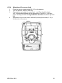
1
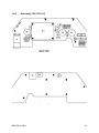
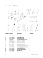
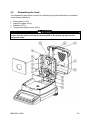
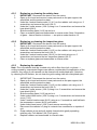
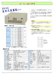
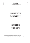
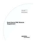
KERN & Sohn GmbH
Ziegelei 1
D-72336 Balingen-Frommern
E-Mail: [email protected]
GB
Service Manual
Electronic Moisture Analyzer
Tel: 0049-[0]7433- 9933-0
Fax: 0049-[0]7433-9933-149
Internet: www.kern-sohn.com
Page 2
KERN MRS 120-3
Version 1.1
02/2008
Contents
1.
ACCESSORIES.............................................................................................................................. 4
1.1
1.2
2.
MECHANICS .................................................................................................................................. 6
2.1
2.2
2.3
2.4
2.5
2.6
2.7
2.8
3.
TEMPERATURE CALIBRATION SET............................................................................................... 4
CONSUMABLES ......................................................................................................................... 5
BOTTOM OF BALANCE ............................................................................................................... 6
TOP OF BALANCE ...................................................................................................................... 8
BASE ..................................................................................................................................... 10
HOOD HALOGEN ..................................................................................................................... 12
HALOGEN RADIATOR UNIT ....................................................................................................... 14
WEIGHING CELL ...................................................................................................................... 16
INTERNAL PARTS .................................................................................................................... 18
MAINS CABLE ......................................................................................................................... 19
ELECTRONICS ............................................................................................................................ 20
3.1
MAIN BOARD320-7215-020 .................................................................................................... 20
3.1.1 Exchange of the main board 320-7215-020 .................................................................... 20
3.1.2 Schematic 320-7215-020................................................................................................. 21
3.1.3 Assembly 320-7215-020.................................................................................................. 28
3.1.4 Parts list 320-7215-020.................................................................................................... 29
3.2
DISPLAY BOARD 330-7204-010 .............................................................................................. 32
3.2.1 Schematic 320-7204-010................................................................................................. 32
3.2.2 Assembly 320-7204-010.................................................................................................. 33
3.2.3 Parts list 320-7204-010.................................................................................................... 34
3.3
HEATING BOARD 330-7200-010.............................................................................................. 35
3.3.1 Schematic 330-7200-010................................................................................................. 35
3.3.2 Assembly 330-7200-010.................................................................................................. 38
3.3.3 Parts list 330-7200-010.................................................................................................... 38
3.4
POWER SUPPLY BOARD 330-7201-010 ................................................................................... 40
3.4.1 Schematic 330-7201-010................................................................................................. 40
3.4.2 Assembly 330-7201-010.................................................................................................. 41
3.4.3 Parts list 330-7201-010.................................................................................................... 42
4.
REPAIRS ...................................................................................................................................... 43
4.1
SERVICE TOOLS AND EQUIPMENT ............................................................................................. 43
4.1.1 Equipment........................................................................................................................ 43
4.1.2 Adjustment set (350-8571) .............................................................................................. 43
4.1.3 Tool set (350-8537) ......................................................................................................... 44
4.2
DISMANTLING THE HOOD ......................................................................................................... 45
4.2.1 Replacing or cleaning the safety class ............................................................................ 46
4.2.2 Replacing or cleaning the inspection glass ..................................................................... 46
4.2.3 Replacing the radiator...................................................................................................... 46
4.2.4 Replacing the temperature safety switch......................................................................... 47
4.3
DISMANTLING THE TOP OF MOISTURE ANALYZER ....................................................................... 48
4.3.1 Replacing the heating board............................................................................................ 49
4.3.2 Replacing the fan ............................................................................................................. 49
4.3.3 Replacing the temperature sensor................................................................................... 49
4.3.4 Replacing or cleaning the plunger ................................................................................... 50
4.4
DISMANTLING THE TOP OF BALANCE......................................................................................... 51
4.4.1 General procedure for opening the balance .................................................................... 52
4.5
INTRODUCTION / PREPARATION OF THE BALANCE ..................................................................... 53
4.5.1 Introduction ...................................................................................................................... 53
4.5.2 Preparation of the tools.................................................................................................... 53
4.6
DISMANTLING THE WEIGHING CELL ........................................................................................... 54
4.6.1 Removing the top of balance ........................................................................................... 54
4.6.2 Removing the weighing cell from the bottom of balance ................................................. 54
4.6.3 Removing the flexure strap.............................................................................................. 54
4.6.4 Removing the two flexure holders ................................................................................... 55
2
MRS-SH-e-0811
4.6.5 Removing coil .................................................................................................................. 55
4.6.6 Removing the support piece ............................................................................................ 55
4.6.7 Removing the balance arm.............................................................................................. 55
4.7
INSTALLING THE NEW FLEXURE SHEETS.................................................................................... 57
4.7.1 Removing the old flexure sheets ..................................................................................... 57
4.7.2 Installing the new flexure sheets...................................................................................... 57
4.8
CLEANING .............................................................................................................................. 58
4.8.1 Cleaning the magnet........................................................................................................ 58
4.8.2 Cleaning the coil .............................................................................................................. 58
4.8.3 Final check of cleaning .................................................................................................... 58
4.9
ASSEMBLING THE WEIGHING CELL ............................................................................................ 59
4.9.1 Assembling the balance arm and the support piece ....................................................... 59
4.9.2 Assembling the coil, the magnet cover and the transport safety device ......................... 60
4.9.3 Assembling the sensor mechanism, the inner cone and the stopper.............................. 60
4.9.4 Assembling the flexure holders........................................................................................ 61
4.9.5 Assembling new flexure sheets ....................................................................................... 62
4.9.6 Assembling a new flexure strap....................................................................................... 62
4.9.7 Dismantling the assembly jigs ......................................................................................... 63
4.9.8 Installing the weighing cell in the bottom of balance ....................................................... 63
4.10
ADJUSTMENTS........................................................................................................................ 64
4.10.1
Activation of the service mode .................................................................................... 64
4.10.2
Adjusting of the symmetry ........................................................................................... 64
4.10.3
Checking the pre-load ................................................................................................. 64
4.10.4
Adjusting of the corner load......................................................................................... 65
4.10.5
Final assembly of the balance..................................................................................... 67
4.10.6
Checking the corner load ............................................................................................ 67
4.10.7
Linearization of the balance ........................................................................................ 67
4.10.8
Final check of the adjustment...................................................................................... 67
4.10.9
S-correction of a balance ............................................................................................ 68
4.10.10 Temperature linearization............................................................................................ 68
4.10.11 Configuration of the heat source ................................................................................. 69
4.10.12 Final check .................................................................................................................. 69
4.11
ERROR MESSAGES ................................................................................................................. 70
4.11.1
Operating error ............................................................................................................ 70
4.11.2
Fatal error .................................................................................................................... 70
4.11.3
Hardware error ............................................................................................................ 70
4.12
DISCUSSION WITH THE MANUFACTURER ................................................................................... 71
MRS-SH-e-0811
3
1.
Accessories
1.1
Key-No.
1
Temperature calibration set
Part-No.
MRS-A01
Description
Temperature calibration set
IMPORTANT: For repair of the temperature calibration set no spare parts are
supplied. The faulty temperature calibration set must be returned for repair to KERN &
Sohn GmbH.
4
MRS-SH-e-0811
1.2
Consumables
1.
2.
Key-No.
1
Part-No.
MLB-A01
Description
Aluminium pans
(80 pieces in a box)
2
RH-A02
Glass fibre papers
(100 pieces in a box)
MRS-SH-e-0811
5
2.
2.1
6
Mechanics
Bottom of balance
MRS-SH-e-0811
Key-No.
Part-No.
Description
1
2
3
4
5
6
7
8
9
10
11
12
13
15
16
17
18
19
20
21
22
23
23
240-4048
320-2010
320-4056
320-7005
320-7015
320-7032-003
320-7204-010
320-7215-020
330-2017
330-7015
330-7020
330-7021
330-7201-010
PN 1100-023
PN 1100-171
PN 1500-010
PN 1500-035
PN 1700-034
PN 3730-001
320-4049
PN 1100-240
PN 3612-006
PN 3612-012
Screw
Cover
Adhesive tape for leveling unit
Bottom of housing
Leveling screw
Measuring resistor
Display board MRS 120-3
Main board MRS 120-3
Cover
Ground wire short
Signal cable
Connecting cable main
Power supply board
Screw M3x6
Screw M4x10
Lock washer M4
Lock washer M4
Rivscrew
Leveling unit
Display holder
Screw KA25x10
Fuse 63mA T 230V
Fuse 125mA T 115V
MRS-SH-e-0811
7
2.2
8
Top of balance
MRS-SH-e-0811
Key-No.
Part-No.
Description
1
2
3
4
5
6
7
8
9
10
11
12
13
330-4012
330-4015
330-7000
330-7008
330-7022
350-4098
F4-184
PN 1100-176
PN 1100-211
PN 1100-216
PN 1100-227
PN 1300-051
PN 1500-010
Rubber bushing
Membrane switches
Top of housing
Cover plate
Identification Label
Display glass
Guidance spring
Screw M4x12
Screw M4x6
Screw M3x6
Screw M4x25
Combo nut M4
Lock washer M4
MRS-SH-e-0811
9
2.3
10
Base
MRS-SH-e-0811
Key-No.
Part-No.
1
2
3
4
5
6
7
8
9
10
11
12
13
14
15
16
16
330-2000
Protection plate
330-2023
Cover
330-3000
Axis
330-3005
Plunger
330-4001
Base
330-7019
Fan
330-7200- Heating board
010
F2-159
Pressure spring
F3-189
Torsion spring
PN 1053-004Rubber stop
PN 1100-054Screw KA30x8
PN 1100-062Screw M3x8
PN 1100-148Screw M4x20
PN 1500-004Lock washer
PN 1500-051Lock washer
PN 3612-315Fuse 3.15A T 230V
PN 3612-630Fuse 6.3A T 115V
MRS-SH-e-0811
Description
11
2.4
12
Hood halogen
MRS-SH-e-0811
Key-No.
Part-No.
Description
1
2
3
4
5
6
7
8
9
10
11
12
13
14
330-2008
330-2009
330-2014
330-2016
330-2020
330-4002
330-4003
330-4007
350-4063
PN 1100-043
PN 1100-064
PN 1100-170
PN 1300-050
330-4007
Glass holder left
Glass holder right
Radiator plate cpl.
Glass holder middle
Insert
Hood
Inserted cover
Inspection glass
Caution label „hot“
Screw D2.9x6.5
Screw M4x6
Screw M4x8
Speed nut D2.9
Inspection glass
MRS-SH-e-0811
13
2.5
14
Halogen radiator unit
MRS-SH-e-0811
Key-No.
Part-No.
Description
1
2
3
4
5
6
7
8
9
10
11
12
13
14
15
16
17
17
18
330-2003
330-4006
330-4009
330-7013
330-7016
330-7023
330-7025
330-8005
F4-182
F4-183
PN 1100-054
PN 1100-208
PN 1100-211
PN 1100-213
PN 1300-051
PN 3500-022
PN 3650-008
PN 3650-009
PN 3650-010
Heat shield
Safety glass
Sensor holding plate
Cover
Radiator unit prebl d cable
Connecting
Radiator cable
Temperature sensor
Mounting clip
Holder spring
Screw KA30x8
Screw KA30x6
Screw M4x6
Screw M4x16
Combo nut M4
U-tab 6.3mm
Halogen radiator 115V
Halogen radiator 230V
Temp. safety switch
MRS-SH-e-0811
15
2.6
16
Weighing cell
MRS-SH-e-0811
Key-No.
Part-No.
Description
1
2
3
4
5
6
7
8
9
10
11
12
300-7024
320-2004
320-2021
320-2032
320-2034
320-2041
320-2045
320-2048
320-3013
320-5019
320-7006
320-8011
13
14
15
16
17
18
19
20
21
22
23
24
25
26
27
28
29
30
31
32
320-8000
320-8010
330-7036
PN 1100-023
PN 1100-040
PN 1100-169
PN 1100-170
PN 1100-171
PN 1100-172
PN 1300-008
PN 1500-001
PN 1500-075
280-2003
PN 1100-039
320-3018
240-4048
320-3019
320-7035
Connecting wire
Flexure holder
Flexure strap Th 1.2mm
Transport safety device
Sensor mechanism plate
Flexure sheet Th 3mm
Flexure sheet Th 3mm
Magnet cover
Base round
Support piece 1:4.5
Coil
Sensor mechanism
(incl. Key-No. 13 and 14)
Sensor board
Connecting board
Chassis
Balance arm 1:4.5
Cone extension
Screw M3x6
Screw M3x8
Screw M4x6
Screw M4x8
Screw M4x10
Screw M4x12
Nut M4
Washer M3
Spring washer M4
Stopper
Screw M3x5
Distance bolt
Symmetry screw
Corner load screw
Magnet
MRS-SH-e-0811
17
2.7
18
Internal parts
Key-No.
Part-No.
Description
1
2
3
330-7003
330-7004
330-7011
Sample holder
Pan support
Wind shield
MRS-SH-e-0811
2.8
Mains cable
1
3
2
4
Key-No.
Part-No.
1
2
3
PN 3602-401 Mains cable CH
PN 3602-400 Mains cable Schuko
PN 3602-402 Mains cable USA
4
PN 3602-403 Mains cable UK
MRS-SH-e-0811
Description
19
3.
3.1
3.1.1
Electronics
Main board320-7215-020
Exchange of the main board 320-7215-020
The new basic version of the main board 320-7215-020 is applicable for moisture
analyzer with software N5x-xxxx-xxx.
The drawing below shows which hardware components are to be converted by an
exchange of a main board.
20
Position
Description
U13
U12
TP1-TP4
EEPROM
Real time clock
Measuring resistor
MRS-SH-e-0811
3.1.2
Schematic 320-7215-020
MRS-SH-e-0811
21
22
MRS-SH-e-0811
MRS-SH-e-0811
23
24
MRS-SH-e-0811
MRS-SH-e-0811
25
26
MRS-SH-e-0811
MRS-SH-e-0811
27
3.1.3
28
Assembly 320-7215-020
MRS-SH-e-0811
3.1.4
Parts list 320-7215-020
Item
Quantity Reference
Type
Part
1
2
1
1
U2
U3
62256
PAGASIC
PN 3023-005
PN 3022-047
3
1
U7
80C52
PN 3022-054
4
1
U21
14C88
PN 3023-001
5
1
U22
14C89
PN 3023-002
6
1
U33
HEF4066
PN 3023-003
7
1
U14
TL7705A
PN 3023-006
8
1
U5
74HC157
PN 3023-008
9
1
U24
74HC240
PN 3023-009
10
2
U6,U23
74HC368
PN 3023-010
11
1
U4
74HC153
PN 3023-012
12
1
U29
DG413
PN 3030-100
13
3
U25,U32,U35
LM358
PN 3030-101
14
3
U28,U30,U31
OP177GS
PN 3030-102
15
2
U17,U27
LF353
PN 3030-103
16
1
U9
LM3524
PN 3031-001
17
2
U18,U20
LM7660S
PN 3031-002
18
1
U10
78L15
PN 3031-003
19
1
U11
79L15
PN 3031-004
20
1
U8
LM2575
PN 3050-200
21
1
Q6
BCP55
PN 3140-001
22
1
Q9
BCP52
PN 3140-002
23
6
Q1,Q7,Q10,Q12,Q13,Q14
BC817
PN 3140-003
24
4
Q4,Q5,Q8,Q11
BC807
PN 3140-004
25
1
Q3
BSP319
PN 3140-005
26
12
D1,D7,D15,D17,D18,D19,D20,D21,D22,D24 BAW56
PN 3145-001
27
1
D26,D27
D14
BAT54C
PN 3145-002
28
4
D2,D3,D10,D13
LL4004G
PN 3145-003
29
6
D4,D5,D8,D9,D11,D12
1N5819M
PN 3145-004
30
1
U19
LM399H
PN 3220-101
31
1
D6
ZPD6.2
PN 3241-962
32
1
D29
ZMM12V
PN 3245-012
33
1
R100
0R
PN 3306-000
34
1
R14
10R
PN 3306-010
35
2
R34,R29
100R
PN 3306-110
36
2
R4,R20
330R
PN 3306-133
37
13
R13,R18,R19,R23,R25,R26,R30,R35,R90,
R98,R99,R104,R105
1k
PN 3306-210
38
3
R66,R68,R70
2k
PN 3306-220
MRS-SH-e-0811
29
Item
Quantity
Reference
Type
Part
39
2
R8,R87
2k2
PN 3306-222
40
1
R24
3k3
PN 3306-233
41
9
R2,R12,R15,R16,R42,R43,R72,R91,R96
4k7
PN 3306-247
42
22
10k
PN 3306-310
43
3
R3,R5,R7,R21,R27,R36,R37,R51,R55,R57,
R58,R59,R60,R61,R64,R67,R69,R73,R77,
R78, R89,R97
R50,R52,R63
15k
PN 3306-315
44
1
R88
5k6
PN 3306-256
45
2
R32,R53
22k
PN 3306-322
46
1
R49
27k
PN 3306-327
47
3
R11,R22,R38
33k
PN 3306-333
48
9
R1,R31,R48,R54,R65,R71,R75,R76,R82
47k
PN 3306-347
49
3
R9,R10,R92
100k
PN 3306-410
50
1
R86
1M
PN 3306-510
51
3
R6,R28,R33
4R7
PN 3306-947
52
2
RN1,RN4
100R
PN 3361-110
53
1
RN2
10k
PN 3361-310
54
1
RN3
47k
PN 3361-347
55
1
C56
100nF
PN 3401-410
56
1
C67
470nF
PN 3401-447
57
1
C37
1u550V
PN 3401-515
58
1
C50
330nF
PN 3420-433
59
3
C8,C16,C17
220uF/35V
PN 3426-722
60
4
C9,C11,C15,C19
47uF/50V
PN 3428-648
61
1
C22
1000uF
PN 3428-810
62
3
C14,C21,C40
10uF/35V
PN 3438-610
63
2
C1,C2
22pF
PN 3440-022
64
1
C77
100pF
PN 3440-110
65
3
C3,C13,C73
1nF
PN 3440-210
66
1
C53
1.8nF
PN 3440-218
67
68
10
24
C4,C5,C10,C26,C28,C33,C36,C78,C79,C80 10nF
C6,C7,C18,C20,C23,C35,C41,C44,C45,C52 100nF
PN 3440-310
PN 3440-410
69
6
,C54,C55,C57,C58,C59,C60,C62,C63,C69,
C70,C71,C72,C74,C76
C31,C32,C51,C61,C66,C68
470nF
PN 3440-447
70
10
C12,C27,C29,C38,C39,C42,C43,C46,C49
10uF/35V
PN 3450-610
71
2
C64
S5,S5
7X2
PN 3502-002
72
1
S1
8X2
PN 3502-003
73
2
J1,S3
1X2
PN 3504-302
74
1
JP1
5X2
PN 3504-310
75
1
S6
1X2
PN 3504-360
30
MRS-SH-e-0811
Item
Quantity Reference
Type
Part
76
1
S4
1X7
PN 3504-368
77
1
LS1
QMP-111P
PN 3607-001
78
2
L1,L2
500uH
PN 3680-002
79
1
QZ1
14.7456MHz
PN 3881-013
80
1
C34
330nF
PN 3421-433
81
2
D16,D23
BZX84C9V1
PN 3244-991
82
1
U1
PLCC32
PN 3023-016
83
1
U12
72421
PN 3022-046
84
1
U13
24C08
PN 3022-053
MRS-SH-e-0811
31
3.2
3.2.1
32
Display board 330-7204-010
Schematic 320-7204-010
MRS-SH-e-0811
3.2.2
Assembly 320-7204-010
MRS-SH-e-0811
33
3.2.3
Parts list 320-7204-010
Item
1
2
3
4
5
6
8
9
10
Quantity
1
1
1
2
2
1
1
2
1
34
Reference
C1
DISPLAY1
D1
Q3,Q1
Q4,Q2
R1
U1
U2,U3
U4
Type
3n3
10-LT-55GK
BAW56
BCP55
BCP52
10k
CD4069
5818EPF
74HC132
Part
PN 3440-233
PN 3260-019
PN 3145-001
PN 3140-001
PN 3140-002
PN 3306-310
PN 3023-004
PN 3022-051
PN 3023-007
MRS-SH-e-0811
3.3
3.3.1
Heating board 330-7200-010
Schematic 330-7200-010
MRS-SH-e-0811
35
36
MRS-SH-e-0811
MRS-SH-e-0811
37
3.3.2
Assembly 330-7200-010
3.3.3
Parts list 330-7200-010
Item
Quantity Reference
Type
1
2
3
4
5
6
7
8
9
10
11
12
13
14
15
16
17
2
1
1
4
3
6
2
5
2
1
2
2
2
1
1
1
1
2200pF
PN 3870-004
0.22uF
PN 3422-422
1uF
PN 3435-510
10uF
PN 3438-610
470nF
PN 3401-447
100nF
PN 3419-340
10nF
PN 3419-310
1N4448
PN 3230-901
1N4007
PN 3210-008
20V
PN 3241-020
BAT48
PN 3210-006
8V2
PN 3241-982
1.5KE220A
PN 3680-100
12V/0.5W
PN 3241-012
RECTIFIERKBPC60PN 3220-010
FAB
PN 3602-111
HEADER 2
PN 3602-301
38
C1,C3
C2
C5
C8,C9,C14,C17
C10,C12,C20
C13,C15,C19,C21,C22,C23
C18,C24
D1,D2,D3,D9,D13
D4,D6
D5
D16,D17
D7,D12
D11,D8
D10
D14
F1
JP2
Part
MRS-SH-e-0811
Item
Quantity Reference
18
19
20
21
22
23
24
25
26
27
28
29
30
31
32
33
34
35
36
37
38
39
40
41
42
43
44
45
46
47
48
49
50
51
1
1
1
5
1
1
2
1
3
1
1
1
2
9
3
1
2
9
8
1
1
1
1
1
1
1
1
1
1
1
1
1
1
2
MRS-SH-e-0811
Type
JP3
HEADER8
JP4
HEADER 7X2
JP5
PT100
LC1,LC2,LC3,LC4,LC5
ZJSR5101-332
LS1
RELAY_5A
L1
B82724-J2402
L2,L3
BL02RN2
MAINS1
GS220P
Q6,Q8,Q10
BC337
Q7
IRFP460
Q9
BC327
R1
910k
R20,R2
100R
R3,R6,R22,R23R30,R47,R50,R57,R5 10k
R4,R18,R16
1K
R21
47k
R25,R43
4k7
R26,R34,R37,R40,R42,R44,R45,R46,220k
R5,R27,R28,R33,R35,R38,R39,R41 100k
R29
56k/2W
R31
22k
R32
0.1/2W
R36
330R
R51
33k
R53
5k6
R54
18k
R55
27k
S1
MSW3P
U1
LM311
U4
74HC4066
U5
78L12/TO92
U6
LMC555
U7
4N35
U8,U9
LP324
Part
PN 3502-101
PN 3502-002
PN 3504-302
PN 3680-007
PN 3604-104
PN 3680-200
PN 3680-008
PN 3602-107
PN 3100-004
PN 3130-024
PN 3100-007
PN 3304-491
PN 3304-110
PN 3304-310
PN 3304-210
PN 3304-347
PN 3304-247
PN 3304-422
PN 3304-410
PN 3305-356
PN 3304-322
PN 3305-901
PN 3304-133
PN 3304-333
PN 3304-256
PN 3304-318
PN 3304-327
PN 3603-013
PN 3030-029
PN 3019-419
PN 3050-022
PN 3030-036
PN 3270-003
PN 3030-037
39
3.4
3.4.1
40
Power supply board 330-7201-010
Schematic 330-7201-010
MRS-SH-e-0811
3.4.2
Assembly 330-7201-010
MRS-SH-e-0811
41
3.4.3
Parts list 330-7201-010
Item
Quantity Reference
Type
1
2
3
4
5
6
7
8
9
10
11
12
13
14
15
16
17
18
19
5
1
2
1
1
7
4
2
1
5
1
1
1
1
1
1
1
1
1
10nF
PN 3419-310
100nF
PN 3419-340
1000uF/50V PN 3428-810
B40C1500G PN 3220-009
FUSE
PN 3602-105
ZJSR5101- PN 3680-007
BL02RN2
PN 3680-008
ZBF253D
PN 3680-003
BC337
PN 3100-004
1k
PN 3304-210
RXE020
PN 3350-300
230V/115VS PN 3602-104
2P U-MNL PN 3602-300
7X2
PN 3502-002
RS232
PN 3502-100
FB-Cable
330-7029
12VDC50MA PN 3602-010
PWRJACK PN 3512-012
TRAFO320 PN 3606-100
42
C1,C7,C8,C9,C10
C2
C3,C4
D1
F1
LC1,LC2,LC3,LC4,LC5,LC6,LC7
L1,L2,L3,L4
L5,L6
Q1
R1,R2,R3,R4,R5
R6
SW1
S1
S2
S3
S4
S5
S6
T1
Par
MRS-SH-e-0811
4.
Repairs
4.1
Service tools and equipment
4.1.1
Equipment
The following basic tools are required:
Part-No.
Description
Soldering iron
Tweezers
Lens
Voltmeter
Socket wrench Nos. 4, 5.5 and 7
Flat-bladed screwdriver No. 1, 2 and 4
Phillips screwdriver Nos. 0 and 2
Tool set series 320
Power supply:
CH
Schuko
USA
UK
AUS
Weight 10g, 20g, 50g, 100g (class F1)
350-8537
350-835x
350-8351
350-8352
350-8353
350-8354
350-8355
4.1.2
Adjustment set (350-8571)
Position
Part-No.
Description
Quantity
1
330-7038
Service membrane switches
1
2
W 41-1716
Service weighing pan
1
MRS-SH-e-0811
43
4.1.3
Tool set (350-8537)
Position
Part-No.
Description
Quantity
1
2
3
4
5
6
7
8
9
10
11
12
13
14
15
W 41-1688
W 41-1688-5
W 41-1688-6
350-6203
240-7124
PW 29.43.300
W 41-1700
W 41-1701
W 41-1677
W 41-1691
W 41-1675
W 41-1674
PN 1100-172
W 41-1699
W 41-1578-8
Mounting plate
Support post, long
Support post, short
Line-head screwdriver M4
Screwdriver, small, no.1
Pin for flexure holder
Assembly jig with slot
Assembly jig with hole
Assembly pin for assembly jig
Centering spigot for flexures
Centering spigot for the coil
Flexure strap anchor
Line-head screw M4x12
Alignment jig
Connecting cable
1
2
2
1
1
2
1
1
4
2
1
1
2
1
1
44
MRS-SH-e-0811
4.2
Dismantling the hood
The dismantling procedure required for replacing the parts listed below is explained
in the following sections:
•
•
•
•
Safety glass (1/4.2)
Inspection glass (2/4.2)
Radiator (3/4.2)
Temperature safety switch (4/4.2)
For maintenance-work, the device must be disconnected from the mains. Also
ensure that the device cannot be reconnected to the mains by anyone else
during the work.
MRS-SH-e-0811
45
4.2.1
1.
2.
3.
4.
5.
6.
4.2.2
1.
2.
3.
4.
5.
4.2.3
Replacing or cleaning the safety class
IMPORTANT: Disconnect the device from the mains.
Open up the hood and remove loose parts such as the pan support, the
windshield and the protection plate.
Undo the 4 socket head screws (11/ 4.2) on the radiator unit using a no. 2
screwdriver and remove the hood (5/4.2).
Undo the 2 collar screws (12/4.2) using a no. 2 screwdriver and remove the
heat shield (6/4.2).
Slide the safety glass (1/4.2) up and out.
Clean or replace glass and reassemble in reverse order (Note: Orientation
of glass – narrow section to bottom → see picture under section 4.2.
Replacing or cleaning the inspection glass
IMPORTANT: Disconnect the device from the mains.
Open up the hood and remove loose parts such as the pan support, the
windshield and the protection plate.
Undo the 4 socket head screws (11/4.2) on the radiator unit using a no. 2
screwdriver and remove the hood (5/4.2).
Undo the 2 socket head screws (14/4.2) on the hood using a no. 0
screwdriver and remove the two inspection glasses (2/4.2).
Clean or replace glass and reassemble in reverse order.
Replacing the radiator
Note: The new radiator shell be touched only with a fibre free cloth, or gloves →
soiling caused by unprotected fingers can reduce considerable life expectation of the
radiator. Any soiling or dirt caused can be cleaned with methylated spirit. Attention:
by cleaning the IR-radiator, do not clean the gold coating side with mehtylated spirit.
1.
2.
3.
4.
5.
6.
7.
8.
9.
10.
11.
46
IMPORTANT: Disconnect the device from the mains.
Open up the hood and remove loose parts such as the pan support, the
windshield and the protection plate.
Undo the 4 socket head screws (11/4.2) on the radiator unit using a no. 2
screwdriver and remove the hood (5/4.2).
Undo the 2 collar screws (12/4.2) using a no. 2 screwdriver and remove the
heat shield (6/4.2).
Slide the safety glass (1/4.2) up and out.
Undo socket head screw (10/4.2) using a no. 0 screwdriver and remove the
cover (7/4.2).
Undo 2 socket head screws (9/4.2) using a no. 0 screwdriver and fold back
the temperature. sensor (8/4.2) and holder.
Undo socket head screw (15/4.2) and remove securing clip.
Disconnect the radiator’s 2 plug-in contacts from connectors on topside of
unit.
Grasp radiator at top and pull slightly forward while gently spreading
retaining clip. Pull radiator (3/4.2) out gently.
Replace radiator and reassemble in reverse order.
MRS-SH-e-0811
4.2.4
1.
2.
3.
4.
5.
6.
7.
8.
9.
Replacing the temperature safety switch
IMPROTANT: Disconnect the device from the mains.
Open up the hood and remove loose parts such as the pan support, the
windshield and the protection plate.
Undo the 4 socket head screws (12/4.2) using a no. 2 screwdriver and
remove the hood (5/4.2).
Undo the 2 collar screws (12/4.2) using a no. 2 screwdriver and remove the
heat shield (6/4.2).
Slide the safety glass (1/4.2) up and out.
Undo socket head screw (10/4.2) using a no. 0 screwdriver and remove the
cover (7/4.2).
Disconnect the temperature safety switch’s 2 plug-in contacts.
Undo the hexagon nut (13/4.2) using the no. 7 socket wrench and remove
the temperature safety switch (4/4.2).
Replace switch and reassemble in reverse order.
MRS-SH-e-0811
47
4.3
Dismantling the top of moisture analyzer
The dismantling procedure required for replacing the parts listed below is explained
in the following sections:
•
•
•
•
Heating board (1/4.3)
Fan (2/4.3)
Temperature sensor (3/4.3)
Plunger (4/4.3)
For maintenance-work, the device must be disconnected from the mains. Also
ensure that the device cannot be reconnected to the mains by anyone else
during the work.
48
MRS-SH-e-0811
4.3.1
1.
2.
3.
4.
5.
6.
7.
8.
4.3.2
1.
2.
3.
4.
5.
6.
7.
8.
9.
4.3.3
1.
2.
3.
4.
Replacing the heating board
IMPORTANT: Disconnect the device from the mains.
Open up the hood and remove loose parts such as the pan support, the
windshield and the protection plate (16/4.3).
Undo the 2 socket head screws (15/4.3 / marked T on the housing) using a
no. 4
screwdriver and gently tip the top of the moisture analyzer (17/4.3)
back.
Disconnect the ribbon cable (8/4.3) and power lead (9/4.3) from the heating board
and remove the top of the moisture analyzer from the balance.
Undo the ground wire's hexagon nut (6/4.3) using the no. 7 socket wrench from
the top of the balance; make sure to leave the lock washer (5/4.3) on the top of
the balance.
Undo 2 socket head screws (7/4.3) from the heating board using the no. 0
screwdriver and 2 socket head screws (14/4.3) from the mains socket (rear
panel) using the no. 2 screwdriver.
Disconnect the plug-in contacts for the temperature sensor, radiator power
supply and fan from the heating board and remove the heating board
(1/4.3).
Replace board and reassemble in reverse order.
Replacing the fan
IMPORTANT: Disconnect the device from the mains.
Open up the hood and remove loose parts such as the pan support, the
windshield and the protection plate (16/4.3).
Undo the 2 socket head screws (15/4.3 / marked T on the housing) using a
no. 4 screwdriver and gently tip the top of the moisture analyzer (17/4.3) back.
Disconnect the ribbon cable (8/4.3) and power lead (9/4.3) from the
heating board (1/4.3) and remove the top of the moisture analyzer from the
balance.
Undo the ground wire's hexagon nut (6/4.3) using the no. 7 socket wrench
from the top of the balance; make sure to leave the lock washer (5/4.3) on the
top of the balance.
Undo 2 socket head screws (7/4.3) from the heating board using the no. 0
screwdriver and 2 socket head screws (14/4.3) from the mains socket (rear
panel) using the no. 2 screwdriver.
Disconnect the plug-in contacts for the temperature sensor, radiator power
supply and fan from the heating board and remove the heating board.
Remove the fan (2/4.3).
Replace fan and reassemble in reverse order.
Replacing the temperature sensor
IMPORTANT: Disconnect the device from the mains.
Open up the hood and remove loose parts such as the pan support, the
windshield and the protection plate (16/4.3).
Undo the 2 socket head screws (15/4.3 / marked T on the housing) using a
no. 4 screwdriver and gently tip the top of the moisture analyzer (17/4.3) back.
Disconnect the ribbon cable (8/4.3) and power lead (9/4.3) from the heating board
(1/4.3) and remove the top of the moisture analyzer from the balance.
MRS-SH-e-0811
49
5.
6.
7.
8.
9.
10.
11.
12.
Undo the ground wire's hexagon nut (6/4.3) using the no. 7 socket wrench from
the top of the balance; make sure to leave the lock washer (5/4.3) on the top of
the balance.
Undo 2 socket head screws (7/4.3) from the heating board using the no. 0
screwdriver and 2 socket head screws (14/4.3) from the mains socket (rear
panel) using the no. 2 screwdriver.
Disconnect the plug-in contacts for the temperature sensor, radiator power
supply and fan from the heating board and remove the heating board.
Undo the 4 socket head screws (12/4.3) on the radiator unit using a no. 2
screwdriver and remove the hood (11/4.3).
Undo the 2 collar screws (19/4.3) using a no. 2 screwdriver and remove
the heat shield (20/4.3).
Slide the safety glass (21/4.3) up and out.
Remove the harness wrap from the cable gland on the radiator unit.
Undo socket head screw (22/4.3) using a no. 0 screwdriver and remove the
cover (23/4.3). 13. Undo 2 socket head screws (10/4.3) using a no. 0
screwdriver and remove the temperature sensor (3/4.3).
Note: When the temperature sensor is replaced, the temperature needs to be adjusted
using calibration set MRS-A01 → Instructions see “Temperature linearization” in chapter
4.10.10.
4.3.4
1.
2.
3.
4.
5.
6.
7.
8.
9.
50
Replacing or cleaning the plunger
IMPORTANT: Disconnect the device from the mains.
Open up the hood and remove loose parts such as the pan support, the
windshield and the protection plate (16/4.3).
Undo 2 socket head screws (15/4.3) using a no. 4 screwdriver and tip the
temperature sensor (17/4.3) back slightly.
Disconnect the ribbon cable (8/4.3) and power lead (9/4.3) from the
heating board (1/4.3) and remove the top of the moisture analyzer from the
balance.
Undo the ground wire’s hexagon nut (6/4.3) using the no. 7 socket wrench
from the top of the balance; make sure to leave the lock washer (5/4.3) on
the top of the balance.
Undo 2 socket head screws (7/4.3) from the heating board using the no. 0
screwdriver and 2 socket head screws (14/4.3) from the mains socket (rear
panel) use the no. 2 screwdriver.
Disconnect the plug-in contacts for the temperature sensor, radiator power
supply and fan from the heating board and remove the heating board.
Take off the lock washer (13/4.3) and remove the plunger (4/4.3) and
spring (18/4.3).
Clean or replace plunger and reassemble in reverse order.
MRS-SH-e-0811
4.4
Dismantling the top of balance
The dismantling procedure required for replacing or repairing the parts listed below is
explained in the following section:
•
•
•
•
Main board (14/4.4)
Power supply (13/4.4)
Weighing cell (2.6)
Display board (7/4.4)
For maintenance-work, the device must be disconnected from the mains. Also
ensure that the device cannot be reconnected to the mains by anyone else
during the work.
MRS-SH-e-0811
51
4.4.1
General procedure for opening the balance
1.
2.
IMPORTANT: Disconnect the device from the mains.
Open up the hood and remove loose parts such as the pan support, the
windshield and the protection plate (1/4.4).
3.
Undo 2 socket head screws (2/4.4 / marked B on the housing) and rear
case securing screw (3/4.4) using a no. 4 screwdriver.
CAUTION: Take care not to damage the sensitive weighing cell during the
following stages of the procedure:
4.
Raise the top of the balance (4/4.4) slightly; disconnect the ribbon cable
(6/4.4) from the power supply board. The connector between the membrane
switches and the main board (7/4.4) must also be detached.
5.
Carefully tilt the top of balance to the left alongside the balance.
Note: The balance is now ready to be adjusted → see “Adjustments” in chapter
4.10. For dismantling the weighing cell (see “Dismantling the weighing cell” on page
4.6) you need to do the following steps:
6.
Remove cylinder screw (8/4.4) with a line-head screwdriver [4/4.1.3] and the
earth cable with the washers (9+10/4.4).
7.
MRS 120-3: Disconnect the power cable from the power supply board (5/4.4)
and remove the top of balance.
8.
The bottom of balance is now ready for further dismantling, see the
following pages.
52
MRS-SH-e-0811
4.5
4.5.1
Introduction / Preparation of the balance
Introduction
In the event of a broken flexure, it is recommended that all flexures be replaced. The
following assembly instructions provide information on how the flexures can be
replaced most efficiently. It is important to employ a structured procedure for
dismantling since it is essential to replace the same parts (particularly screws) in the
same place when re-assembling.
The various items of the assembly instructions mean:
Component items.
[5/4.1]: Tooling items see “Service tools and equipment” in chapter 4.1.
Example: 3 nuts (24/2.6) means 3 nuts as Item 26 in chapter 2.6.
4.5.2
Preparation of the tools
Before dismantling the balance it is necessary to carry out some preparation of the
tools. 2 long [2/4.1.3] and 2 short [3/4.1.3] support posts must be screwed into the
correct places on the assembly plate [1/4.1.3] → see the drawing below and in
chapter 4.1.3.
The soldering iron should be plugged in or preheated.
MRS-SH-e-0811
53
4.6
4.6.1
1.
4.6.2
1.
2.
3.
4.
5.
6.
4.6.3
1.
2.
54
Dismantling the weighing cell
Removing the top of balance
→ see “Dismantling the top of balance” in chapter 4.4.
Removing the weighing cell from the bottom of balance
On the main board, unplug the sensor mechanism plug (12/2.6) using a
small screwdriver.
Turn over the bottom of balance and unscrew the 3 nuts (24/2.6) on the
underside of the housing.
Hold the weighing cell only on the chassis and lift it out of the bottom of
housing.
The chassis can now be placed on the assembly plate for easier handling.
To protect the weighing cell, the two assembly jigs [7/4.1.3] + [8/4.1.3] are
introduced in accordance with the drawing see drawing in chapter 4.6.2 and
secured with the 4 assembly pins [9/4.1.3].
Assemble the two assembly jigs [7] + [8] and 4 assembly pins [9] in
accordance with the drawing in chapter 4.6.2.
Removing the flexure strap
Undo 2 screws (23/2.6), remove flexure strap (3/2.6) incl. bases (9/2.6)
and spring washers (26/2.6) → do not separate screw components,
assemble in same relationship!
Screw the flexure strap anchor [12/4.1.3] on tightly with 2 screws [13/4.1.3]
in place of the flexure strap.
MRS-SH-e-0811
4.6.4
1.
2.
3.
4.
6.
4.6.5
1.
2.
3.
4.
4.6.6
1.
2.
4.6.7
Removing the two flexure holders
Using the two pins for flexure holder [6/4.1.3] fix the upper flexure holder
(2/2.6) into the chassis.
Unscrew the 4 screws (22/2.6) of the upper flexure holder and remove
together with the 4 spring washers (26/2.6) → 2 on the chassis, 2 on the
support piece.
Remove the two pins with the upper flexure holder incl. 4 spring washers
and the flexure sheets, then take out the pins from the flexure holder.
Fix the lower flexure holder (2/2.6) into the chassis with the two pins for
flexure holder [6/4.1.3]. 5. Unscrew 4 screws (22/2.6) from the lower
flexure holder and remove together with the 4 spring washers → 2 on the
chassis, 2 on the support piece.
Take out both pins with the lower flexure holder and remove the lower flexure
holder together with the 4 spring washers and the flexure sheets.
Removing coil
Carefully unsolder 2 connecting wires (1/2.6) from the connecting board
(14/2.6) using the tweezers.
Unscrew 3 screws (21/2.6) from the magnet cover (8/2.6), remove the
cover together with transport safety device (4/2.6) and spring washer
(s26/2.6).
Unscrew 2 brass screws (19/2.6) from the coil (11/2.6) on the balance arm
(16/2.6) using a No.2 screwdriver, remove the coil together with the washer
(25/2.6).
Carefully take out the coil from the magnet (32/2.6).
Removing the support piece
Unscrew 2 screws (21/2.6) on the inner cone (17/2.6) and remove inner
cone.
Unscrew upper screw (balance arm side) of the flexure strap anchor
[12/4.1.3] and pull off the support piece together with the flexure strap anchor
over the assembly pins [9/4.1.3].
Removing the balance arm
1.
Unscrew brass screw (28/2.6) from the stopper (27/2.6), turn the stopper
inwards ca. 90° and gently re-tighten the brass screw.
2.
Unscrew the 4 screws (23/2.6) from the flexure sheets (6/2.6) and remove
both flexure sheets together with the bases (9/2.6) and spring washers
(26/2.6).
Note: Since the lug of the sensor mechanism is firmly attached to the balance arm,
the sensor mechanism must be unscrewed to dismantle the balance arm and
gently tilted back:
3.
Unscrew 2 screws (18/2.6) from the sensor mechanism plate (5/2.6) and
remove the plate.
4.
Unscrew screw (18/2.6) from the connecting board (14/2.6).
5.
Unscrew 2 screws (20/2.6) of the sensor mechanism and gently tilt the
sensor mechanism to the rear.
6.
Remove the two inner assembly pins [9/4.1.3] → unscrew from the balance
arm.
MRS-SH-e-0811
55
7.
9.
10.
56
Remove the two outer assembly pins [9/4.1.3] → unscrew from the chassis.
8. Remove the two assembly jigs [7/4.1.3] + [8/4.1.3].
Carefully tilt the balance arm (16/2.6) over the magnet (32/2.6) and the
sensor mechanism and take out.
Further dismantling of the weighing cell is unnecessary.
MRS-SH-e-0811
4.7
4.7.1
1.
4.7.2
7.2
1.
2.
3.
4.
5.
Installing the new flexure sheets
Removing the old flexure sheets
Take out all screws from the flexure holder and remove the old flexure
sheets together with spring washers.
Installing the new flexure sheets
Place a flexure holder on the assembly plate [1/
[1/4.1.3]
4.1.3] as in the drawing
below.
Place 4 new flexure sheets (7/2.6) part-no. 320-2045 carefully on the
assembly plate as in the drawing below → the slot of the sheet is always on
the flexure holder.
Place 4 spring washers (26/2.6) on the flexure sheet and screw these
tightly to the flexure holder with 4 screws (20/2.6).
Take the complete flexure holder carefully off the assembly plate → do not
touch the flexures!
Prepare the second flexure holder in the same way.
MRS-SH-e-0811
57
4.8
4.8.1
1.
2.
3.
4.
5.
6.
4.8.2
1.
2.
4.8.3
1.
58
Cleaning
Cleaning the magnet
Cut strips of a double-sided adhesive tape (ca. 2x2 cm).
Wind the adhesive tape around one end of a toothpick.
Introduce the toothpick, adhesive tape first, vertically into the annular gap.
With circular movements move it repeatedly around the magnet. In this way
any dirt particles stick to the adhesive tape.
If necessary, repeat the procedure with a freshly prepared toothpick until the
annular gap is free from impurities.
Wipe over the top of magnet with a piece of adhesive tape.
Cleaning the coil
Using a lint-free cloth, remove any contamination from the coil.
Do not clean the coil with adhesive tape; risk of injury!
Final check of cleaning
Visually inspect the annular gap and the coil for any contamination and
clean if necessary.
MRS-SH-e-0811
4.9
4.9.1
1.
2.
3.
4.
5.
6.
7.
8.
9.
10.
11.
12.
Assembling the weighing cell
Assembling the balance arm and the support piece
To facilitate the assembly, the chassis can be placed on the assembly
plate → attention to the sensor mechanism!
Pre-assemble assembly jigs [7] + [8] with 2 assembly pins [9] on the
chassis as in the drawing below.
Adjust assembly jigs [7] + [8] using the alignment jig [14] horizontally in
accordance with the drawing below and tighten the two assembly pins [9]
with a No. 4 socket wrench.
Carefully introduce the balance arm (16/2.6) over the magnet (32/2.6) and
past it to the sensor mechanism.
Assemble the balance arm with 2 assembly pins [9] loosely behind the
assembly jigs. The balance arm must remain moveable.
Introduce the pre-assemble support piece (10/2.6) over the two inner
assembly posts [9] → see the drawing on page 60.
It must be possible to push the support piece smoothly over the two
assembly pins.
Locate the support piece and the balance arm using the flexure strap
anchor [12] and the two screws [13] → see the drawing on page 60.
The right inner assembly pin of the assembly jig [8] can now be firmly
tightened.
The left inner assembly pin of the assembly jig [7] can now be firmly tightened.
Firmly tighten the two screws [13] of the fixed flexure strap anchor [12].
The support piece and the balance arm are now fixed.
MRS-SH-e-0811
59
4.9.2
1.
2.
3.
4.
5.
6.
4.9.3
1.
2.
4.
5.
6.
7.
60
Assembling the coil, the magnet cover and the transport safety
device
Place the coil onto the balance arm and centre with the centering spigot
[11/4.1.3].
Screw the coil tightly onto the balance arm with 2 brass screws (19/2.6) and 2
washers (25/2.6).
The coil must be centered in such a way that the centering spigot can be
removed smoothly.
Pre-assemble the magnet cover (8/2.6) with 2 screws (21/2.6) → screws left and
right.
Pre-assemble the transport safety device (4/2.6) with the third screw (21/2.6) and
spring washer (26/2.6) → gently tighten.
Adjust the transport safety device in the balance arm in such a way that the
transport safety device does not touch the balance arm and a uniform annular
gap is formed → visual check with the lens.
Assembling the sensor mechanism, the inner cone and the
stopper
Press the sensor mechanism carefully into the cutout in the chassis in the
direction of the magnet and secure to the chassis with 2 screws (20/2.6).
Firmly screw the connecting board (14/2.6) onto the chassis with screw
(18/2.6). 3. Fix the sensor mechanism plate (5/2.6) with 2 screws (18/2.6)
to the chassis.
Solder the two connecting wires (1/2.6) in parallel and strain-free to the
connecting board (14/2.6).
Assemble the inner cone (17/2.6) to the support piece with 2 screws (21/2.6).
Turn back the stopper (27/2.6) with brass screw (28/2.6) by 90° and screw
tight.
The stopper must be free of play and lie centrally in the symmetry screw
(30/2.6) → if necessary, re-adjust symmetry screw.
MRS-SH-e-0811
4.9.4
1.
2.
3.
4.
5.
6.
7.
8.
Assembling the flexure holders
Introduce the two pins for flexure holder [6] in the first pre-assembled
flexure holder (see “Installing the new flexure sheets” in chapter 4.7.2) in
such a way that the shoulder of the pins is opposite the screw heads on
the flexure holder.
Bring the two pins with the flexure holder into position in the chassis → see
drawing below.
Lower the flexure holder carefully over the two pins on the chassis, until the
flexure sheets just touches the chassis and the support piece.
Secure the flexure holder with 4 screws (22/2.6) and 4 spring washers
(26/2.6).
Push through the two pins up to the installed flexure holder.
On the opposite side introduce the second pre-assembled flexure holder (see
“Installing the new flexure sheets” in chapter 4.7) with the screw heads
inwards over the two pins and lower onto the chassis, until the flexure
sheets just touches the chassis and the support piece.
Secure the flexure holder with 4 screws (22/2.6) and 4 spring washers
(26/2.6).
The two pins must be capable of being withdrawn smoothly from the
flexure holder.
MRS-SH-e-0811
61
4.9.5
1.
2.
3.
4.
5.
6.
4.9.6
1.
2.
3.
4.
5.
6.
7.
62
Assembling new flexure sheets
Bring 2 flexure sheet (6/2.6) part-no. 320-2041 into position as in the drawing
below → slots are on the support piece side (below).
With a centering spigot [10], centre the flexure sheet in the hole on the chassis
side (above).
With the second centering spigot [10], centre the flexure sheet in the slot
on the support piece side (below).
Tighten the first (upper) centering spigot and then remove the second
(lower) centering spigot, without touching the flexure sheet in doing so.
Fasten the flexure sheet on the support piece side with base (9/2.6), spring
washer (26/2.6) and screw (23/2.6) → see drawing below.
Remove the second (upper) centering spigot and fasten the flexure sheet
on the chassis side with base (9/2.6), spring washer (26/2.6) and screw
(23/2.6).
Assembling a new flexure strap
Unscrew 2 screws [13] on the flexure strap anchor [12] and remove it.
Bring the flexure strap (3/2.6) part-no. 320-2021 into position as shown in the
drawing on page 63 → the slot is on the support piece side.
Using a centering spigot [10], centre the flexure strap in the hole on the
balance arm side.
With the second centering spigot [10] centre the flexure strap in the slot on the
support piece side.
Tighten the first (upper) centering spigot and then carefully remove the
second (lower) centering spigot, without touching the flexure strap.
Fasten the flexure strap on the support piece side with base (9/2.6), spring
washer (26/2.6) and screw (23/2.6) → see the drawing on page 63.
Remove the second (upper) centering spigot and fasten the flexure strap on
the balance arm side with base (9/2.6), spring washer (26/2.6) and screw
(23/2.6).
MRS-SH-e-0811
4.9.7
1.
2.
3.
4.
4.9.8
Dismantling the assembly jigs
Unscrew and remove the two inner assembly pins [9] on the support piece.
Unscrew and remove the two outer assembly pins [9] on the support piece.
Take out the two assembly jigs [7] + [8] from the side.
If the two assembly pins [6] on the flexure holder (2/2.6) are still
assembled, remove them carefully.
Installing the weighing cell in the bottom of balance
1.
Carry out a further movement check on the balance arm → the balance arm
must not touch the transport safety device (4/2.6)! Visual check with the lens.
2.
Place the weighing cell carefully in the bottom of housing → hold the
weighing cell only to the chassis.
3.
Tilt the bottom of housing to the side and screw the weighing cell securely
from below with 3 nuts (24/2.6).
4.
Carefully connect the sensor mechanism plug (12/2.6) to the main board
(8/2.1).
5.
Lay the top of balance (4/4.4) on the left beside the bottom of balance and
connect the internal power supply cable (5/4.4) on the connector board
IMPORTANT: Tighten earth cable with cylinder-head screw (8/4.4) incl. washers
(9+10/4.4) on the bottom of balance.
6.
The balance is now ready for the adjustments explained on the following
pages.
MRS-SH-e-0811
63
4.10
4.10.1
Activation of the service mode
1.
Push and hold simultaneously the TARE- and PRINT-key for approx. 10
sec. whilst switching on the balance after connected the power cable.
As soon „SET SERVICE MODE“ appears in the display, then release the
two keys.
2.
3.
4.
. „CODE 0“ appears in the display.
Push the CHANGE-key
Press ENTER-key. „CODE 0000“ appears in the display.
With the arrow keys insert the code „5236“ and confirm with the ENTERkey.
The balance is now in service mode.
5.
4.10.2
1.
3.
4.
5.
4.10.3
1.
2.
3.
64
Adjustments
Adjusting of the symmetry
Connect the connecting cable [15/4.1.3] from the tool set to plug
(S3/4.10.1.1) on the main board. 2. Connect the voltmeter to the
connecting cable.
The voltmeter must show approximately the same voltage in the end
positions of the balance arm (one positive, one negative).
If the difference is too great, the position of the balance arm can be
adjusted with the symmetry screw.
Detach connecting cable and voltmeter from the balance.
Checking the pre-load
The pre-load error ERROR 60 (below minimal converter range) must not
appear when the service weighing pan is in position without load.
The pre-load error ERROR 61 (above maximal converter range) must not
appear when the service weighing pan is in position with full load.
If an ERROR is displayed, the symmetry must be re-adjusted and the
transport safety device adjusted from the start → see “Assembling the coil,
the magnet cover and the transport safety device” in chapter 4.9.2.
MRS-SH-e-0811
4.10.4
1.
2.
3.
4.
Adjusting of the corner load
Place the service weighing pan [3/4.1.2] on the balance.
Tare the balance with the TARE-key.
Check with a test weight for corner load → see “Final check” in chapter
4.10.12 the deviation between the two diagonals A-C and B-D → see next
page. The diagonal with the larger absolute deviation should be adjusted
first.
Adjustment of the corner load is effected by turning the screws (1 + 2) in
the direction of the arrow.
MRS-SH-e-0811
65
Example of corner load adjustment:
1.
The diagonal A-C has the larger
difference.
2.
Place a test weight at point C of the
weighing pan. Tare the balance
using the TARE-key.
3.
Move the weight to point A.
4.
There is a difference of 12 digits
between points A and C (A=12,
C=Tare=0).
5.
The displayed value for point A is
reduced by turning the corner load
screw 1 above point A in a clockwise
direction → the difference between AC becomes smaller.
6.
There is a difference of 7 digits
between points B and D (B=-7,
D=Tare=0).
7. The displayed value for point B is
reduced by turning the corner load
screw 2 above point B in an anticlockwise direction →the difference
between B-D becomes smaller.
8.
The diagonals A-C and B-D should
be repeatedly adjusted until the two diagonals have reached the permitted
tolerances for corner load → see “Final check” in chapter 4.10.12.
9.
Place a test weight on point Z of the weighing pan, tare balance using the
TARE-key. 10. Check the points A-B-C-D against the permitted tolerances
and correct if necessary.
66
MRS-SH-e-0811
4.10.5
1.
2.
3.
4.
5.
6.
7.
8.
9.
4.10.6
1.
2.
4.10.7
1.
2.
3.
4.
5.
6.
8.
9.
10.
4.10.8
1.
2.
3.
4.
5.
Final assembly of the balance
Disconnect the balance from the mains, pull out the mains cable or power
supply. If a power supply has been used, re-attach the cover (9/2.1).
The service weighing pan [3/4.1.2] and the service membrane switches
[2/4.1.2] must be removed from the balance.
Reconnect the ribbon cable to the power supply board. Reconnect the
ribbon cable of the membrane switches to the main board (D1/4.10.1.1).
IMPORTANT: Screw up the ground wire on the bottom of balance.
Check: ensure that the power supply cable (5/4.4) is connected to the
power supply board.
CAUTION: Pay attention that during the following operating sequence the
weighing cell will not be damaged and no cable will be caught.
Place the two parts of the housing together and fasten with 3 screws.
Protection plate, windshield and pan support must be inserted.
The balance must have attained its operating temperature before further
adjustment can be carried out.
Checking the corner load
The balance must have reached its operating temperature.
Check the corner load tolerance → see “Adjusting of the corner load” in
chapter 4.10.4.
Linearization of the balance
The balance must have reached its operating temperature and be in the
service mode → see “Activation of the service mode” (chapter 4.10.1)
Have weights of 1/2 full load and full load ready → see “Final check” in
chapter 4.10.12.
Press and hold CHANGE-key
until "LINEARITY" appears on the info
display, then release the key.
With empty service weighing pan [3/4.1.2] press the function-key F1 "0" →
balance will flash on.
Place a 1/2 full load weight in the centre of the weighing pan.
Press the function-key F2 "1/2" → balance will flash on. 7. Place a full load
weight in the centre of the weighing pan.
Press the function-key F3 "1/1" → balance will flash on.
Press the function-key F4 "SET" → balance will flash on and show the
value for the full load.
Now exit the service mode by pressing the ON/OFF-key.
Final check of the adjustment
The balance must have reached its operating temperature, for that assure
that balance is connected at least three hours to the mains.
Calibrate the balance by holding TARE-key till „CAL EXT“ appears →
release TARE-key.
Check the corner load → see “Adjusting of the corner load” in chapter
4.10.4.
Check the linearity with half weight and full weight.
Carry out any S-corrections → see “S-correction of a balance” see chapter
4.10.9.
MRS-SH-e-0811
67
4.10.9
S-correction of a balance
4.10.9.1
General notes on S-correction
•
The balance must have reached its operating temperature and must be in
service mode.
• In every linearization of a balance the correction factor is deleted and must, if
necessary, be redefined.
4.10.9.2
1.
2.
4.10.9.3
•
•
•
4.10.9.4
1.
2.
3.
4.
Entry of the correction factor
lace a weight of 1/4 full load in the centre of the weighing pan, note the
difference between the actual weight and the weight indicated by the
balance.
lace a weight of 3/4 full load in the centre of the weighing pan, note the
difference between the actual weight and the weight indicated by the
balance.
Calculating the correction factor
For the correction factor the sign of the measured value must be reversed.
For example: + 4 digits were measured →- 4 digits must be entered.
For example: - 2 digits were measured →+ 2 digits must be entered.
Entry of the correction factor
Press and hold down the CHANGE-key
until "SCORRECTION"
appears on the Info-Display, then release the key.
Using the function-key F2 "SECTOR" the correction range Sa or Sb is
established.
Using the function-key F3 "UP" and F4 "DOWN" the chosen correction
factor is entered and set with the function-key F1 "SET".
Submit the balance to a further final check → see “Final check” in chapter
4.10.12.
4.10.10 Temperature linearization
1.
2.
3.
68
The balance has to be set in service mode → see “Activation of the service
mode” (chapter 4.10.1)
The temperature-calibration set part-no. 350-8570 (page A2) needs to be
connected to the RS232 Interface, located at the back of the moisture
analyzer.
Put the temperature sensor of the temperature-calibration set into the
sample chamber.
4.
Press and hold the CHANGE-key
LINEARISATION“, release the key.
until the Info-Display shows „TEMP
5.
Press the START/STOP-key
, the temperature linearization starts now.
Note: Within the first two minutes, the room temperature will measured. After
that, the moisture analyzer heats up to 100°. The display indicates the
MRS-SH-e-0811
6.
temperature and the remaining time for the temperature linearization (the
time duration to heat up to 100°C, is 20 minutes). The moisture analyzer will
now adopt the temperature from temperature-calibration set. Afterwards the
moisture analyzer will heat up to 200°C which takes 20 minutes to reach. As
before, the moisture analyzer will again adopt the temperature from the
temperature-calibration set.
The temperature is now linearized and the temperature-calibration set can
now be disconnected. 7. Using the ON/OFF-key switch the balance off and
on, the service mode is now exited.
4.10.11 Configuration of the heat source
1.
The balance must be set in service mode → see “Activation of the service
mode” in chapter 4.10.1.
2.
as long as in the Info-Display “HEAPress and hold the CHANGE-key
TER CONFIG.” appears → release the key.
4.10.12 Final check
Review of the final tolerances (reproducibility, linearity and corner load).
MRS-SH-e-0811
69
4.11
4.11.1
Error Messages
Operating error
(Error disappears with correct use or application)
Error-No.
Error 1
Error 2
Error 4
Error 5
Error 8
Error 9/0
Error 9/1
Error 47
Error 48
Error 49
Error 53
Error 60
Error 61
4.11.2
Error responsibility
Invalid program
Weight too small
Wrong anti-theft-code
Wrong anti-theft-code
Zero point outside range
Calibration factor bad
Zero point difference too high
Too many values
Different first unit from input
Too few values
Values out of range +/- 50%
Fallen below minimum transformer area
Maximum transformer area exceeded
Error repair
Load right program
Use higher weight
Use right code
Use right code
Repeat calibration
Repeat calibration
Use fewer values
Use original unit
Use more values
Use appropriate weight
Fatal error
(Balance stays still, error repair in service mode)
Error-No.
Error 10
Error 11
Error 22
Error 26
Error 27
4.11.3
Error responsibility
No linearization values
No calibration factor
No temperature compensation values
Missing temperature-linearization-value in
moisture analyzer
Missing temperature-calibration-value in
moisture analyzer
Error repair
Repeat linearization
Repeat calibration
Call service
Temperature linearization
Temperature calibration
Hardware error
(Balance stays still)
Error-No.
Error 14
Error 16
Error 17
Error 18/1
Error responsibility
Wrong model code
Internal RAM destroyed
External RAM destroyed
Wrong program check sum
Error 18/2
No approved program build in approved
balance
FLASH empty
Error 18/8
Error 18/9
Error 19
Error 20
Error 28
70
Wrong controller check sum
Wrong code figure
Temperature measurement defective
Temperature measurement moisture
analyzer defective
Error repair
Call service
Replace CPU
Replace RAM
Load right program,
replace FLASH
Load right program
Load right program,
replace FLASH
Replace CPU
Load right code figure
Call service
Call service
MRS-SH-e-0811
4.12
Discussion with the manufacturer
In discussions with the manufacturer’s works the following information should be
provided:
• Balance type (e.g. MRS 120-3)
• Series number e.g. 330-65 (Label on the rear of the balance)
• Program number e.g. 00,00P00 N50 (appears on the display when switching on
the balance)
• As precise a description of the defect as possible
• Weighing results
• Drying settings
• Preparation of the samples
MRS-SH-e-0811
71