1
V5812G
GPON OLT system
User Manual
UMN:CLI
※ Copyright 2011 ⓒ DASAN Networks, Inc.
Issued by Technical Documentation Team
Korea
Technical modifications possible.
Technical specifications and features are binding only insofar as
they are specifically and expressly agreed upon in a written contract.
2
User Manual
V5812G
User Manual
V5812G
UMN:CLI
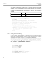
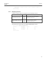
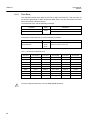
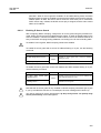
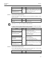
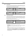
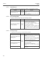
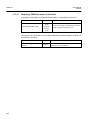
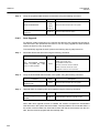
Contents of Update
Issue No. 1
Chapter/Section
Contents
All
Initial release
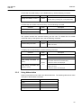
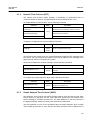
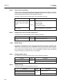
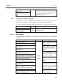
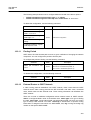
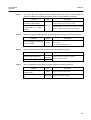
Issue History
Issue
Date
Update
May. 2011
Initial release (NOS version 4.80)
Number
01
3
UMN:CLI
User Manual
V5812G
Contents
1 Introduction ....................................................................................... 25
1.1
1.2
1.3
1.4
1.5
1.6
Audience............................................................................................... 25
Document Structure .............................................................................. 25
Document Convention .......................................................................... 26
Document Notation ............................................................................... 26
Virus Protection .................................................................................... 27
GPL/LGPL Warranty and Liability Exclusion ........................................ 27
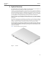
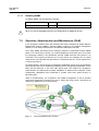
2 System Overview .............................................................................. 29
2.1
System Features .................................................................................. 30
3 Command Line Interface (CLI) ......................................................... 33
3.1
Configuration Mode .............................................................................. 33
3.1.1
3.1.2
3.1.3
3.1.4
3.1.5
3.1.6
3.1.7
3.1.8
3.1.9
3.1.10
3.1.11
3.1.12
3.1.13
Privileged EXEC View Mode ...................................................................... 34
Privileged EXEC Enable Mode .................................................................. 34
Global Configuration Mode ........................................................................ 35
Bridge Configuration Mode ........................................................................ 35
DHCP Pool Configuration Mode ................................................................ 36
DHCP Option Configuration Mode ............................................................. 36
DHCP Option 82 Configuration Mode ........................................................ 37
Interface Configuration Mode ..................................................................... 37
Rule Configuration Mode ........................................................................... 38
RMON Configuration Mode ........................................................................ 38
Router Configuration Mode ........................................................................ 39
Route-Map Configuration Mode ................................................................. 39
GPON Configuration Mode ........................................................................ 40
3.1.13.1 GPON-OLT Configuration Mode .................................................................... 40
3.1.13.2 ONU Profile Configuration Mode ................................................................... 40
3.2
3.3
Configuration Mode Overview .............................................................. 41
Useful Tips ............................................................................................ 42
3.3.1
3.3.2
3.3.3
3.3.4
3.3.5
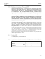
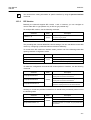
Listing Available Command ........................................................................ 42
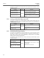
Calling Command History .......................................................................... 44
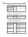
Using Abbreviation ..................................................................................... 45
Using Command of Privileged EXEC Enable Mode .................................. 46
Exit Current Command Mode .................................................................... 46
4 System Connection and IP Address ................................................ 47
4.1
System Connection .............................................................................. 47
4.1.1
4.1.2
4.1.3
4.1.4
System Login ............................................................................................. 47
Password for Privileged EXEC Enable Mode ............................................ 48
Changing Login Password ......................................................................... 49
Management for System Account .............................................................. 49
4.1.4.1
4.1.4.2
4.1.5
4.1.6
4.1.7
4.1.8
4
Creating System Account............................................................................... 49
Security Level ................................................................................................ 50
Limiting Number of Users........................................................................... 54
Auto Log-out ............................................................................................... 54
Telnet Access ............................................................................................. 54
System Rebooting ...................................................................................... 55
User Manual
V5812G
UMN:CLI
4.1.8.1
4.1.9
4.1.9.1
4.1.9.2
4.1.9.3
4.2
Authentication Method ................................................................................59
Authentication Interface ..............................................................................59
Primary Authentication Method ...................................................................60
RADIUS Server ...........................................................................................60
4.2.4.1
4.2.4.2
4.2.4.3
4.2.4.4
4.2.5
4.2.6
4.2.7
TACACS+ Server for System Authentication .................................................. 61
TACACS+ Server Priority ............................................................................... 61
Timeout of Authentication Request ................................................................ 62
Additional TACACS+ Configuration ................................................................ 62
Accounting Mode ........................................................................................63
Displaying System Authentication ...............................................................63
Configuring Interface............................................................................. 64
4.3.1
4.3.2
4.3.3
4.3.4
4.3.5
Enabling Interface .......................................................................................64
Assigning IP Address to Network Interface .................................................65
Static Route and Default Gateway ..............................................................65
Interface Description ...................................................................................66
Displaying Interface ....................................................................................67
Secure Shell (SSH) ............................................................................... 68
4.4.1
SSH Server .................................................................................................68
4.4.1.1
4.4.1.2
4.4.1.3
4.4.1.4
4.4.1.5
4.4.2
Enabling SSH Server ..................................................................................... 68
Displaying On-line SSH Client........................................................................ 68
Disconnecting SSH Client .............................................................................. 68
Assigning Specific Authentication Key............................................................ 69
Displaying Connection History of SSH Client ................................................. 69
SSH Client...................................................................................................69
4.4.2.1
4.4.2.2
4.4.2.3
4.5
RADIUS Server for System Authentication .................................................... 60
RADIUS Server Priority .................................................................................. 60
Timeout of Authentication Request ................................................................ 61
Frequency of Retransmit ................................................................................ 61
TACACS+ Server ........................................................................................61
4.2.5.1
4.2.5.2
4.2.5.3
4.2.5.4
4.4
CPU Load ...................................................................................................... 56
Memory .......................................................................................................... 56
Network Connection ....................................................................................... 57
System Authentication .......................................................................... 59
4.2.1
4.2.2
4.2.3
4.2.4
4.3
Manual System Rebooting ............................................................................. 55
Auto Reset Configuration ............................................................................56
Login to SSH Server ...................................................................................... 69
Secured File Copy.......................................................................................... 69
Authentication Key ......................................................................................... 70
802.1x Authentication............................................................................ 71
4.5.1
802.1x Authentication..................................................................................72
4.5.1.1
4.5.1.2
4.5.1.3
4.5.1.4
4.5.1.5
4.5.1.6
4.5.1.7
4.5.1.8
4.5.2
Enabling 802.1x ............................................................................................. 72
RADIUS Server .............................................................................................. 72
Authentication Mode ...................................................................................... 73
Authentication Port ......................................................................................... 74
Force Authorization ........................................................................................ 74
Interval for Retransmitting Request/Identity Packet ....................................... 74
Number of Requests to RADIUS Server ........................................................ 74
Interval of Request to RADIUS Server ........................................................... 75
802.1x Re-Authentication............................................................................75
4.5.2.1
Enabling 802.1x Re-Authentication ................................................................ 75
5
UMN:CLI
User Manual
V5812G
4.5.2.2
4.5.2.3
4.5.2.4
4.5.3
4.5.4
4.5.5
4.5.6
4.5.7
Interval of Re-Authentication.......................................................................... 76
Interval of Requesting Re-Authentication ...................................................... 76
802.1x Re-Authentication .............................................................................. 76
Initializing Authentication Status ................................................................. 77
Restoring Default Value ............................................................................. 77
Displaying 802.1x Configuration ................................................................ 77
802.1x User Authentication Statistics ......................................................... 77
Sample Configuration................................................................................. 78
5 Port Configuration ............................................................................ 79
5.1
Port Basic ............................................................................................. 79
5.1.1
5.2
Selecting Port Type .................................................................................... 79
Ethernet Port Configuration .................................................................. 79
5.2.1
5.2.2
5.2.3
5.2.4
5.2.5
5.2.6
5.2.7
Enabling Ethernet Port ............................................................................... 79
Auto-Negotiation ........................................................................................ 80
Transmit Rate ............................................................................................. 80
Duplex Mode .............................................................................................. 81
Flow Control ............................................................................................... 81
Port Description .......................................................................................... 81
Traffic Statistics .......................................................................................... 82
5.2.7.1
5.2.7.2
5.2.7.3
5.2.8
5.3
Packet Statistics ............................................................................................. 82
CPU Statistics ................................................................................................ 82
Protocol Statistics .......................................................................................... 84
Port Information .......................................................................................... 84
Port Mirroring ........................................................................................ 85
6 System Environment ........................................................................ 87
6.1
Environment Configuration ................................................................... 87
6.1.1
6.1.2
6.1.3
6.1.4
6.1.5
6.1.6
6.1.7
6.1.8
6.1.9
6.1.10
6.1.11
6.1.12
6.1.13
Host Name ................................................................................................. 87
Time and Date ............................................................................................ 87
Time Zone .................................................................................................. 88
Network Time Protocol (NTP) .................................................................... 89
Simple Network Time Protocol (SNTP) ...................................................... 89
Terminal Configuration ............................................................................... 91
Login Banner .............................................................................................. 91
DNS Server ................................................................................................ 91
Fan Operation ............................................................................................ 92
Disabling Daemon Operation ..................................................................... 92
FTP Server ................................................................................................. 93
FTP Bind Address ...................................................................................... 93
System Threshold ...................................................................................... 94
6.1.13.1
6.1.13.2
6.1.13.3
6.1.13.4
6.1.13.5
6.1.13.6
CPU Load ...................................................................................................... 94
Port Traffic ..................................................................................................... 94
Fan Operation ................................................................................................ 95
System Temperature ...................................................................................... 96
System Memory ............................................................................................. 96
System/SFP Module Operation ..................................................................... 96
6.1.14 Enabling DDM ............................................................................................ 97
6.2
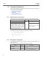
Configuration Management .................................................................. 98
6.2.1
6
Displaying System Configuration ............................................................... 98
User Manual
V5812G
UMN:CLI
6.2.2
6.2.3
6.2.4
6.2.5
6.2.6
6.3
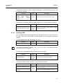
Writing System Configuration .....................................................................98
Auto-Saving.................................................................................................99
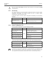
System Configuration File ...........................................................................99
Restoring Default Configuration ................................................................100
Core Dump File .........................................................................................101
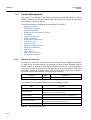
System Management .......................................................................... 102
6.3.1
6.3.2
6.3.3
6.3.4
6.3.5
6.3.6
6.3.7
6.3.8
6.3.9
6.3.10
6.3.11
6.3.12
6.3.13
6.3.14
6.3.15
6.3.16
6.3.17
Network Connection ..................................................................................102
IP ICMP Source Routing ...........................................................................104
Tracing Packet Route................................................................................105
Displaying User Connecting to System ....................................................106
MAC Table.................................................................................................107
System Running Time ...............................................................................107
System Information ...................................................................................107
System Memory Information .....................................................................108
CPU Packet Limit ......................................................................................108
Running Process .......................................................................................108
Displaying System Software .....................................................................109
Displaying Installed OS .............................................................................109
Default OS.................................................................................................109
Switch Status............................................................................................. 110
Tech Support Information .......................................................................... 110
System Boot Information........................................................................... 110
Network Service Module (NSM) Daemon Debugging .............................. 111
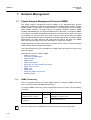
7 Network Management ..................................................................... 112
7.1
Simple Network Management Protocol (SNMP) ................................. 112
7.1.1
7.1.2
7.1.3
7.1.4
7.1.5
7.1.6
7.1.7
7.1.8
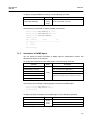
SNMP Community..................................................................................... 112
Information of SNMP Agent ...................................................................... 113
SNMP Com2sec........................................................................................ 114
SNMP Group ............................................................................................. 114
SNMP View Record .................................................................................. 115
Permission to Access SNMP View Record ............................................... 115
SNMP Version 3 User ............................................................................... 116
SNMP Trap................................................................................................ 116
7.1.8.1
7.1.8.2
7.1.8.3
7.1.8.4
7.1.8.5
7.1.9
SNMP Trap Mode ......................................................................................... 116
SNMP Trap Host .......................................................................................... 117
Enabling SNMP Trap .................................................................................... 117
Disabling SNMP Trap ................................................................................... 119
Displaying SNMP Trap ................................................................................. 119
SNMP Alarm..............................................................................................120
7.1.9.1
7.1.9.2
7.1.9.3
7.1.9.4
7.1.9.5
7.1.9.6
7.1.9.7
Alarm Notify Activity ..................................................................................... 120
Alarm Severity Criterion ............................................................................... 120
Default Alarm Severity .................................................................................. 121
Generic Alarm Severity ................................................................................ 121
ADVA Alarm Severity .................................................................................... 123
STP Guard Alarm Severity ........................................................................... 124
Displaying SNMP Alarm ............................................................................... 124
7.1.10 Displaying SNMP Configuration................................................................124
7.1.11 Disabling SNMP ........................................................................................125
7.2
Operation, Administration and Maintenance (OAM) ........................... 125
7
UMN:CLI
User Manual
V5812G
7.2.1
7.2.2
7.2.3
7.2.4
7.2.5
7.2.6
7.3
Link Layer Discovery Protocol (LLDP) ................................................ 130
7.3.1
7.3.2
7.3.3
7.3.4
7.3.5
7.3.6
7.3.7
7.4
Enabling OAM .......................................................................................... 126
OAM Link Monitoring................................................................................ 127
EFM OAM Mode ...................................................................................... 128
OAM Loopback ........................................................................................ 128
OAM Unidirection ..................................................................................... 129
Displaying EFM OAM Configuration ........................................................ 129
LLDP Operation ....................................................................................... 130
Enabling LLDP ......................................................................................... 130
LLDP Operation Type ............................................................................... 130
Basic TLV ................................................................................................. 130
LLDP Message ......................................................................................... 131
Reinitiating Delay ..................................................................................... 131
Displaying LLDP Configuration ................................................................ 132
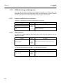
Remote Monitoring (RMON) ............................................................... 133
7.4.1
RMON History .......................................................................................... 133
7.4.1.1
7.4.1.2
7.4.1.3
7.4.1.4
7.4.1.5
7.4.1.6
7.4.1.7
7.4.2
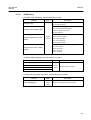
RMON Alarm ............................................................................................ 135
7.4.2.1
7.4.2.2
7.4.2.3
7.4.2.4
7.4.2.5
7.4.2.6
7.4.2.7
7.4.2.8
7.4.2.9
7.4.3
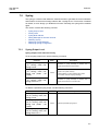
Syslog Output Level ................................................................................. 141
Facility Code ............................................................................................ 143
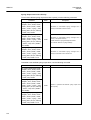
Syslog Bind Address ................................................................................ 144
Debug Message for Remote Terminal ..................................................... 144
Disabling Syslog....................................................................................... 144
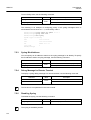
Displaying Syslog Message ..................................................................... 145
Displaying Syslog Configuration .............................................................. 145
Rule and QoS ..................................................................................... 146
7.6.1
8
Event Community ........................................................................................ 139
Event Description......................................................................................... 139
Subject of RMON Event ............................................................................... 139
Event Type ................................................................................................... 139
Activating RMON Event ............................................................................... 140
Deleting Configuration of RMON Event ....................................................... 140
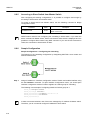
Syslog ................................................................................................. 141
7.5.1
7.5.2
7.5.3
7.5.4
7.5.5
7.5.6
7.5.7
7.6
Subject of RMON Alarm ............................................................................... 136
Object of Sample Inquiry.............................................................................. 136
Absolute and Delta Comparison .................................................................. 136
Upper Bound of Threshold ........................................................................... 136
Lower Bound of Threshold ........................................................................... 137
Standard of the First Alarm .......................................................................... 137
Interval of Sample Inquiry ............................................................................ 138
Activating RMON Alarm ............................................................................... 138
Deleting Configuration of RMON Alarm ....................................................... 138
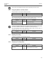
RMON Event ............................................................................................ 138
7.4.3.1
7.4.3.2
7.4.3.3
7.4.3.4
7.4.3.5
7.4.3.6
7.5
Source Port of Statistical Data ..................................................................... 134
Subject of RMON History ............................................................................. 134
Number of Sample Data .............................................................................. 134
Interval of Sample Inquiry ............................................................................ 134
Activating RMON History ............................................................................. 134
Deleting Configuration of RMON History ..................................................... 135
Displaying RMON History ............................................................................ 135
How to Operate QoS ................................................................................ 147
User Manual
V5812G
UMN:CLI
7.6.2
Packet Classification .................................................................................148
7.6.2.1
7.6.2.2
7.6.2.3
7.6.2.4
7.6.2.5
7.6.3
Packet Conditioning ..................................................................................153
7.6.3.1
7.6.3.2
7.6.3.3
7.6.3.4
7.6.4
Admin Policy Creation .................................................................................. 168
Admin Policy Priority .................................................................................... 169
Admin Policy Action...................................................................................... 169
Applying and Modifying Admin Policy ........................................................... 170
Displaying Admin Rule ..............................................................................170
Scheduling ................................................................................................171
7.6.9.1
7.6.9.2
7.6.9.3
7.6.9.4
7.6.9.5
7.6.9.6
7.7
7.8
7.9
7.10
Creating Admin Flow for packet classification .............................................. 165
Configuring Admin Flow ............................................................................... 166
Applying and modifying Admin Flow............................................................. 167
Class Creation.............................................................................................. 167
Admin Rule Action .....................................................................................168
7.6.7.1
7.6.7.2
7.6.7.3
7.6.7.4
7.6.8
7.6.9
Policy Creation ............................................................................................. 155
Metering ....................................................................................................... 156
Policy Priority ............................................................................................... 162
Policy Action ................................................................................................. 162
Setting CoS and ToS values......................................................................... 163
Attaching a Policy to an interface ................................................................. 163
Applying and Modifying Policy...................................................................... 164
Displaying Rule .........................................................................................164
Admin Rule................................................................................................165
7.6.6.1
7.6.6.2
7.6.6.3
7.6.6.4
7.6.7
Policer Creation............................................................................................ 153
Packet Counter ............................................................................................ 154
Rate-limit ...................................................................................................... 154
Applying and modifying Policer .................................................................... 154
Rule Action ................................................................................................155
7.6.4.1
7.6.4.2
7.6.4.3
7.6.4.4
7.6.4.5
7.6.4.6
7.6.4.7
7.6.5
7.6.6
Flow Mode ................................................................................................... 149
Flow Creation ............................................................................................... 149
Configuring Flow .......................................................................................... 150
Applying and modifying Flow........................................................................ 152
Class Creation.............................................................................................. 152
Scheduling mode ......................................................................................... 173
Weight and Quantum ................................................................................... 173
Maximum and Minimum Bandwidth ............................................................. 174
Limiting traffic and buffer .............................................................................. 174
The Traffic of Queue .................................................................................... 175
Displaying QoS ............................................................................................ 175
NetBIOS Filtering ................................................................................ 176
Martian Filtering .................................................................................. 177
Max Host ............................................................................................. 178
Port Security ....................................................................................... 179
7.10.1 Port Security on Port .................................................................................179
7.10.2 Port Security Aging ...................................................................................180
7.10.3 Displaying Port Security ............................................................................181
7.11 Outband Management Port Security................................................... 181
7.12 MAC Table .......................................................................................... 181
7.13 MAC Filtering ...................................................................................... 183
7.13.1 Default MAC Filter Policy ..........................................................................183
9
UMN:CLI
User Manual
V5812G
7.13.2 Configuring MAC Filter Policy .................................................................. 183
7.13.3 Listing MAC Filter Policy .......................................................................... 184
7.13.4 Displaying MAC Filter Policy .................................................................... 184
7.14 Address Resolution Protocol (ARP) ................................................... 185
7.14.1 ARP Table ................................................................................................ 185
7.14.1.1 Registering ARP Table ................................................................................. 185
7.14.1.2 ARP Log Interval .......................................................................................... 186
7.14.1.3 Displaying ARP Table................................................................................... 186
7.14.2 ARP Alias ................................................................................................. 186
7.14.3 ARP Inspection......................................................................................... 187
7.14.3.1
7.14.3.2
7.14.3.3
7.14.3.4
7.14.3.5
7.14.3.6
ARP Access List .......................................................................................... 188
Enabling ARP Inspection Filtering ................................................................ 190
ARP Address Validation ............................................................................... 190
ARP Inspection on Trust Port ....................................................................... 191
ARP Inspection Log-buffer ........................................................................... 191
Displaying ARP Inspection ........................................................................... 192
7.14.4 Gratuitous ARP ........................................................................................ 193
7.14.5 Proxy ARP ................................................................................................ 193
7.15 ICMP Message Control ...................................................................... 195
7.15.1 Blocking Echo Reply Message ................................................................ 195
7.15.2 Interval for Transmit ICMP Message ........................................................ 196
7.16 TCP Flag Control ................................................................................ 197
7.16.1 RST Configuration .................................................................................... 197
7.16.2 SYN Configuration ................................................................................... 198
7.17 Packet Dump ...................................................................................... 198
7.17.1
7.17.2
7.17.3
7.17.4
7.17.5
Packet Dump by Protocol......................................................................... 198
Packet Dump with Option......................................................................... 199
Debug Packet Dump ................................................................................ 200
Displaying Dump Packets ........................................................................ 200
Dump File ................................................................................................. 200
7.18 Access List ......................................................................................... 202
7.18.1
7.18.2
7.18.3
7.18.4
7.18.5
Standard Access List ................................................................................ 203
Extended Access List ............................................................................... 204
Named Access List................................................................................... 206
Access List Range ................................................................................... 207
Displaying Access List Entries ................................................................. 208
8 System Main Functions .................................................................. 209
8.1
Virtual Local Area Network (VLAN) .................................................... 209
8.1.1
Port-based VLAN ..................................................................................... 210
8.1.1.1
8.1.1.2
8.1.1.3
8.1.1.4
8.1.2
8.1.3
8.1.4
8.1.5
8.1.6
8.1.7
10
Creating VLAN ............................................................................................. 211
Specifying PVID ........................................................................................... 211
Adding Port to VLAN .................................................................................... 211
Deleting VLAN ............................................................................................. 211
Protocol-based VLAN............................................................................... 212
MAC-based VLAN .................................................................................... 212
Subnet-based VLAN ................................................................................ 213
Tagged VLAN ........................................................................................... 213
VLAN Description ..................................................................................... 214
VLAN Precedence.................................................................................... 215
User Manual
V5812G
UMN:CLI
8.1.8
8.1.9
Displaying VLAN Information ....................................................................215
QinQ ..........................................................................................................215
8.1.9.1
8.1.9.2
8.1.9.3
Double Tagging Operation............................................................................ 216
Double Tagging Configuration ...................................................................... 217
TPID Configuration ....................................................................................... 217
8.1.10 Layer 2 Isolation ........................................................................................218
8.1.10.1 Port Isolation ................................................................................................ 218
8.1.10.2 Shared VLAN ............................................................................................... 219
8.1.11 VLAN Translation ......................................................................................221
8.1.12 Sample Configuration ...............................................................................221
8.2
Link Aggregation (LAG)....................................................................... 224
8.2.1
Port Trunk..................................................................................................224
8.2.1.1
8.2.1.2
8.2.1.3
8.2.2
Link Aggregation Control Protocol (LACP) ...............................................225
8.2.2.1
8.2.2.2
8.2.2.3
8.2.2.4
8.2.2.5
8.2.2.6
8.2.2.7
8.2.2.8
8.2.2.9
8.3
Configuring Port Trunk ................................................................................. 224
Disabling Port Trunk ..................................................................................... 225
Displaying Port Trunk ................................................................................... 225
Configuring LACP ........................................................................................ 226
Distribution Mode ......................................................................................... 226
Operation Mode ........................................................................................... 227
Priority of Switch .......................................................................................... 228
Manual Aggregation ..................................................................................... 228
BPDU Transmission Rate ............................................................................ 229
Administrational Key .................................................................................... 229
Port Priority .................................................................................................. 229
Displaying LACP Configuration .................................................................... 230
Spanning-Tree Protocol (STP) ............................................................ 231
8.3.1
8.3.2
8.3.3
8.3.4
8.3.5
STP Operation ..........................................................................................232
RSTP Operation ........................................................................................235
MSTP Operation .......................................................................................240
Configuring STP/RSTP/MSTP/PVSTP/PVRSTP Mode (Required) .........242
Configuring STP/RSTP/MSTP ..................................................................242
8.3.5.1
8.3.5.2
8.3.5.3
8.3.5.4
8.3.5.5
8.3.5.6
8.3.5.7
8.3.5.8
8.3.5.9
8.3.6
Configuring PVSTP/PVRSTP ...................................................................247
8.3.6.1
8.3.6.2
8.3.6.3
8.3.6.4
8.3.7
8.3.8
8.3.9
Activating STP/RSTP/MSTP ........................................................................ 242
Root Switch .................................................................................................. 242
Path-cost ...................................................................................................... 243
Port-priority................................................................................................... 244
MST Region ................................................................................................. 244
MSTP Protocol ............................................................................................. 245
Point-to-point MAC Parameters ................................................................... 245
Edge Ports ................................................................................................... 246
Displaying Configuration .............................................................................. 246
Activating PVSTP/PVRSTP.......................................................................... 248
Root Switch .................................................................................................. 249
Path-cost ...................................................................................................... 249
Port-priority................................................................................................... 249
Root Guard................................................................................................249
Restarting Protocol Migration....................................................................250
BPDU Configuration..................................................................................251
8.3.9.1
8.3.9.2
Hello Time .................................................................................................... 251
Forward Delay .............................................................................................. 252
11
UMN:CLI
User Manual
V5812G
8.3.9.3
8.3.9.4
8.3.9.5
8.3.9.6
8.3.9.7
Max Age ....................................................................................................... 252
BPDU Hop ................................................................................................... 252
BPDU Filter .................................................................................................. 253
BPDU Guard ................................................................................................ 253
Displaying BPDU Configuration ................................................................... 254
8.3.10 Sample Configuration............................................................................... 254
8.4
Ethernet Ring Protection (ERP) .......................................................... 257
8.4.1
8.4.2
8.4.3
8.4.4
ERP Mechanism ...................................................................................... 257
Loss of Test Packet (LOTP) ..................................................................... 261
ERP Shared Link ...................................................................................... 261
Configuring ERP Domian ......................................................................... 262
8.4.4.1
8.4.4.2
8.4.4.3
8.4.4.4
8.4.5
8.4.6
8.4.7
8.4.8
8.4.9
8.4.10
8.4.11
8.4.12
8.4.13
8.4.14
8.4.15
8.5
8.6
Protected Activation ................................................................................. 263
Primary/Secondary Port State .................................................................. 263
Learning Disable Time ............................................................................. 263
Wait-to-Restore Time ............................................................................... 264
Test Packet Interval .................................................................................. 264
ERP Ring Priority ..................................................................................... 265
LOTP Hold Off Time ................................................................................. 265
ERP Trap .................................................................................................. 266
Registering ERP MAC .............................................................................. 266
Private VLAN with ERP ............................................................................ 266
Displaying ERP Configuration .................................................................. 267
Loop Detection ................................................................................... 268
Dynamic Host Configuration Protocol (DHCP) ................................... 270
8.6.1
DHCP Server............................................................................................ 271
8.6.1.1
8.6.1.2
8.6.1.3
8.6.1.4
8.6.1.5
8.6.1.6
8.6.1.7
8.6.1.8
8.6.1.9
8.6.1.10
8.6.1.11
8.6.1.12
8.6.1.13
8.6.1.14
8.6.1.15
8.6.1.16
8.6.1.17
8.6.1.18
8.6.2
DHCP Pool Creation .................................................................................... 272
DHCP Subnet .............................................................................................. 272
Range of IP Address .................................................................................... 272
Default Gateway .......................................................................................... 273
IP Lease Time .............................................................................................. 273
DNS Server.................................................................................................. 274
Manual Binding ............................................................................................ 274
Domain Name .............................................................................................. 275
DHCP Server Option.................................................................................... 275
Static Mapping ............................................................................................. 275
Recognition of DHCP Client......................................................................... 276
IP Address Validation ................................................................................... 276
Authorized ARP ........................................................................................... 276
Prohibition of 1:N IP Address Assignment.................................................... 277
Ignoring BOOTP Request ............................................................................ 278
DHCP Packet Statistics................................................................................ 278
Setting DHCP Pool Size .............................................................................. 279
Displaying DHCP Pool Configuration ........................................................... 279
DHCP Address Allocation with Option 82 ................................................ 280
8.6.2.1
8.6.2.2
12
ERP Domain ................................................................................................ 262
ERP Domain Description ............................................................................. 262
Node Mode .................................................................................................. 262
Primary and Secondary Port ........................................................................ 262
DHCP Class Capability ................................................................................ 280
DHCP Class Creation .................................................................................. 280
User Manual
V5812G
UMN:CLI
8.6.2.3
8.6.2.4
8.6.2.5
8.6.3
DHCP Lease Database .............................................................................282
8.6.3.1
8.6.3.2
8.6.3.3
8.6.4
Enabling DHCP Snooping ............................................................................ 292
DHCP Trust State ......................................................................................... 292
DHCP Filter on Trust Port............................................................................. 293
DHCP Rate Limit .......................................................................................... 293
DHCP Lease Limit ........................................................................................ 294
Source MAC Address Verification ................................................................ 295
Static DHCP Snooping Binding .................................................................... 295
DHCP Snooping Database Agent ................................................................ 295
ARP Inspection Start Time ........................................................................... 296
DHCP Snooping with Option82 .................................................................... 296
DHCP Snooping Option ............................................................................... 297
Displaying DHCP Snooping Configuration ................................................... 298
IP Source Guard .......................................................................................298
8.6.8.1
8.6.8.2
8.6.8.3
8.6.9
Enabling DHCP Option 82............................................................................ 289
Option 82 Sub-Option .................................................................................. 289
Option 82 Reforwarding Policy ..................................................................... 290
Option 82 Trust Policy .................................................................................. 291
DHCP Snooping ........................................................................................291
8.6.7.1
8.6.7.2
8.6.7.3
8.6.7.4
8.6.7.5
8.6.7.6
8.6.7.7
8.6.7.8
8.6.7.9
8.6.7.10
8.6.7.11
8.6.7.12
8.6.8
Entering DHCP Option Mode ....................................................................... 286
Configuring DHCP Option Format ................................................................ 287
Deleting DHCP Option Format ..................................................................... 287
Displaying DHCP option ............................................................................... 287
DHCP Option 82 .......................................................................................288
8.6.6.1
8.6.6.2
8.6.6.3
8.6.6.4
8.6.7
DHCP Helper Address.................................................................................. 284
Smart Relay Agent Forwarding .................................................................... 284
DHCP Server ID Option ............................................................................... 285
DHCP Relay Statistics .................................................................................. 285
DHCP Option ............................................................................................286
8.6.5.1
8.6.5.2
8.6.5.3
8.6.5.4
8.6.6
DHCP Database Agent................................................................................. 282
Displaying DHCP Lease Status .................................................................... 282
Deleting DHCP Lease Database .................................................................. 283
DHCP Relay Agent ...................................................................................283
8.6.4.1
8.6.4.2
8.6.4.3
8.6.4.4
8.6.5
Relay Agent Information Pattern .................................................................. 280
Associating DHCP Class .............................................................................. 281
Range of IP Address for DHCP Class .......................................................... 281
Enabling IP Source Guard............................................................................ 299
Static IP Source Binding ............................................................................... 300
Displaying IP Source Guard Configuration ................................................... 300
DHCP Client ..............................................................................................300
8.6.9.1
8.6.9.2
8.6.9.3
8.6.9.4
8.6.9.5
8.6.9.6
8.6.9.7
8.6.9.8
Enabling DHCP Client .................................................................................. 300
DHCP Client ID ............................................................................................ 300
DHCP Class ID ............................................................................................ 301
Host Name ................................................................................................... 301
IP Lease Time .............................................................................................. 301
Requesting Option ....................................................................................... 301
Forcing Release or Renewal of DHCP Lease .............................................. 301
Displaying DHCP Client Configuration ......................................................... 302
8.6.10 DHCP Filtering ..........................................................................................302
8.6.10.1 DHCP Packet Filtering ................................................................................. 302
8.6.10.2 DHCP Server Packet Filtering ...................................................................... 303
13
UMN:CLI
User Manual
V5812G
8.6.11 Debugging DHCP..................................................................................... 304
8.7
Virtual Router Redundancy Protocol (VRRP) ..................................... 305
8.7.1
Configuring VRRP .................................................................................... 306
8.7.1.1
8.7.1.2
8.7.1.3
8.7.1.4
8.7.1.5
8.7.1.6
8.7.2
VRRP Monitoring and Management ........................................................ 312
8.7.2.1
8.7.2.2
8.7.2.3
8.8
Associated IP Address ................................................................................. 306
Access to Associated IP Address ................................................................. 306
Master Router and Backup Router .............................................................. 306
VRRP Track Function .................................................................................. 309
Authentication Password ............................................................................. 311
Preempt ....................................................................................................... 311
Displaying VRRP Protocol Information ........................................................ 312
VRRP Statistics ............................................................................................ 312
VRRP Debug ............................................................................................... 313
Single IP Management ....................................................................... 314
8.8.1
8.8.2
8.8.3
8.8.4
8.8.5
8.8.6
Switch Group ............................................................................................ 314
Designating Master and Slave Switch ..................................................... 315
Disabling Cascading ................................................................................ 315
Displaying Cascading Status ................................................................... 315
Accessing to Slave Switch from Master Switch ....................................... 316
Sample Configuration............................................................................... 316
8.9 Rate Limit ........................................................................................... 318
8.10 Flood Guard........................................................................................ 319
8.10.1 MAC Flood Guard .................................................................................... 319
8.10.2 CPU Flood Guard..................................................................................... 320
8.10.3 System Flood Guard ................................................................................ 320
8.11
8.12
8.13
8.14
8.15
8.16
PPS Control ........................................................................................ 322
Storm Control...................................................................................... 323
Jumbo Frame Capacity ...................................................................... 323
Bandwidth ........................................................................................... 324
Maximum Transmission Unit (MTU) ................................................... 324
Blocking Packet Forwarding ............................................................... 324
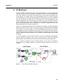
9 IP Multicast ...................................................................................... 325
9.1
Multicast Group Membership .............................................................. 327
9.1.1
IGMP Basic .............................................................................................. 327
9.1.1.1
9.1.1.2
9.1.1.3
9.1.1.4
9.1.2
IGMP Version 2 ........................................................................................ 329
9.1.2.1
9.1.2.2
9.1.2.3
9.1.2.4
9.1.3
9.1.4
9.2
IGMP Static Join .......................................................................................... 330
IGMP Access Control ................................................................................... 332
IGMP Querier Configuration ........................................................................ 332
IGMP Immediate Leave ............................................................................... 334
IGMP Version 3 ........................................................................................ 335
Displaying IGMP Information ................................................................... 336
Multicast Functions ............................................................................. 337
9.2.1
Multicast Forwarding Database................................................................ 337
9.2.1.1
14
IGMP Version ............................................................................................... 328
Querier‘s Robustness Variable .................................................................... 328
Clearing IGMP Entry .................................................................................... 328
IGMP Debug ................................................................................................ 329
Blocking Unknown Multicast Traffic ............................................................. 337
User Manual
V5812G
UMN:CLI
9.2.1.2
9.2.1.3
9.2.2
IGMP Snooping Basic ...............................................................................339
9.2.2.1
9.2.2.2
9.2.2.3
9.2.3
Enabling MVR .............................................................................................. 353
MVR Group .................................................................................................. 353
Source/Receiver Port ................................................................................... 354
MVR Helper Address .................................................................................... 354
Displaying MVR Configuration ..................................................................... 354
IGMP Filtering and Throttling ....................................................................355
9.2.7.1
9.2.7.2
9.2.7.3
9.2.8
IGMP Snooping Querier Configuration ......................................................... 341
IGMP Snooping Last Member Query Interval............................................... 343
IGMP Snooping Immediate Leave ............................................................... 344
IGMP Snooping Report Suppression ........................................................... 345
IGMP Snooping S-Query Report Agency ..................................................... 345
Explicit Host Tracking ................................................................................... 346
Multicast Router Port Configuration ............................................................. 347
TCN Multicast Flooding ................................................................................ 349
IGMPv3 Snooping .....................................................................................351
Displaying IGMP Snooping Information ....................................................351
Multicast VLAN Registration (MVR) ..........................................................353
9.2.6.1
9.2.6.2
9.2.6.3
9.2.6.4
9.2.6.5
9.2.7
Enabling IGMP Snooping ............................................................................. 340
IGMP Snooping Version ............................................................................... 340
IGMP Snooping Robustness Value .............................................................. 341
IGMPv2 Snooping .....................................................................................341
9.2.3.1
9.2.3.2
9.2.3.3
9.2.3.4
9.2.3.5
9.2.3.6
9.2.3.7
9.2.3.8
9.2.4
9.2.5
9.2.6
Forwarding Entry Aging ................................................................................ 338
Displaying McFDB Information ..................................................................... 338
IGMP Filtering .............................................................................................. 355
IGMP Throttling ............................................................................................ 357
Displaying IGMP Filtering and Throttling ...................................................... 357
IGMP Proxy ...............................................................................................358
9.2.8.1
9.2.8.2
9.2.8.3
9.2.8.4
9.2.8.5
9.2.8.6
9.2.8.7
9.2.8.8
Designating Downstream Interface .............................................................. 358
Designating Upstream Interface ................................................................... 358
Configuring Upstream Interface Mode ......................................................... 359
IGMP-Proxy IF Flap Discredit....................................................................... 359
Disabling Verification of Source IP of IGMP Packets.................................... 361
Specifying IGMP Report/Leave‘s Source IP Address ................................... 361
Querying with Real Querirer‘s Source IP Address........................................ 362
Displaying IGMP Proxy Information ............................................................. 362
9.2.9 IGMP State Limit .......................................................................................362
9.2.10 Multicast-Source Trust Port.......................................................................363
9.3
Multicast Routing ................................................................................ 364
9.3.1
Multicast Routing ......................................................................................364
9.3.1.1
9.3.1.2
9.3.1.3
9.3.1.4
9.3.1.5
9.3.1.6
9.3.1.7
9.3.1.8
9.3.2
Enabling Multicast Routing ........................................................................... 364
TTL Threshold .............................................................................................. 364
ECMP Load Splitting .................................................................................... 365
MRIB Entry Limit .......................................................................................... 365
Displaying MRIB Entry ................................................................................. 366
Displaying MRIB Statistics ........................................................................... 367
Displaying MFIB Information ........................................................................ 367
MRIB Debug................................................................................................. 368
PIM Basic ..................................................................................................368
9.3.2.1
9.3.2.2
PIM Mode ..................................................................................................... 369
DR Priority .................................................................................................... 369
15
UMN:CLI
User Manual
V5812G
9.3.2.3
9.3.2.4
9.3.2.5
9.3.2.6
9.3.2.7
9.3.2.8
9.3.2.9
9.3.3
PIM-SM .................................................................................................... 374
9.3.3.1
9.3.3.2
9.3.3.3
9.3.3.4
9.3.3.5
9.3.3.6
9.3.4
Neighbor Filtering ........................................................................................ 370
PIM Join/Prune Message Group Filtering .................................................... 371
PIM Hello Message ...................................................................................... 371
PIM Join/Prune Interval ............................................................................... 372
PIM VIF Flap Discredit ................................................................................. 372
PIM Static Join ............................................................................................. 373
Displaying PIM Information .......................................................................... 373
Rendezvous Point ........................................................................................ 376
Bootstrap Router .......................................................................................... 378
Source Registration ..................................................................................... 379
SPT Switchover ........................................................................................... 381
Cisco‘s Router Interoperability ..................................................................... 382
PIM Debug ................................................................................................... 383
Source Specific Multicast (SSM) .............................................................. 384
9.3.4.1
9.3.4.2
PIM-SSM ..................................................................................................... 384
Static SSM Mapping .................................................................................... 385
10 IP Routing Protocol ......................................................................... 387
10.1 Border Gateway Protocol (BGP) ........................................................ 387
10.1.1 Basic Configuration .................................................................................. 388
10.1.1.1 Configuration Type of BGP .......................................................................... 388
10.1.1.2 Enabling BGP Routing ................................................................................. 388
10.1.1.3 Disabling BGP Routing ................................................................................ 389
10.1.2 Advanced Configuration ........................................................................... 389
10.1.2.1
10.1.2.2
10.1.2.3
10.1.2.4
10.1.2.5
10.1.2.6
10.1.2.7
Summary of Path ......................................................................................... 389
Automatic Summarization of Path ................................................................ 390
BGP Next-Hop Address Tracking ................................................................. 390
Local Preference.......................................................................................... 391
Multi-Exit Discriminator (MED) ..................................................................... 391
Choosing Best Path ..................................................................................... 392
Graceful Restart ........................................................................................... 393
10.1.3 Administrative Distance for BGP .............................................................. 394
10.1.4 IP Address Family .................................................................................... 395
10.1.5 BGP Neighbor .......................................................................................... 395
10.1.5.1
10.1.5.2
10.1.5.3
10.1.5.4
10.1.5.5
10.1.5.6
10.1.5.7
10.1.5.8
10.1.5.9
Default Route ............................................................................................... 395
Peer Group .................................................................................................. 396
Route Map ................................................................................................... 397
Force Shutdown ........................................................................................... 397
Changing the Nexthop Information .............................................................. 397
Neighbor Password ..................................................................................... 398
Neighbor Description ................................................................................... 398
Source of Routing Updates .......................................................................... 398
Updates for Inbound Soft Reconfiguration ................................................... 399
10.1.6 BGP Timers .............................................................................................. 399
10.1.7 Route Flap Dampening ............................................................................ 399
10.1.8 BGP Session Reset ................................................................................. 401
10.1.8.1
10.1.8.2
10.1.8.3
10.1.8.4
16
Session Reset of All Peers........................................................................... 401
Session Reset of Peers within Particular AS................................................ 402
Session Reset of Specific Route .................................................................. 403
Session Reset of External Peer ................................................................... 403
User Manual
V5812G
UMN:CLI
10.1.8.5 Session Reset of Peer Group....................................................................... 404
10.1.9 Displaying and Managing BGP .................................................................405
10.1.9.1
10.1.9.2
10.1.9.3
10.1.9.4
BGP Neighbor .............................................................................................. 405
Logging Neighbor Changes ......................................................................... 406
Checking the BGP Network Route ............................................................... 406
Sending SNMP Trap .................................................................................... 406
10.1.10 BGP Debug ...............................................................................................407
10.2 Open Shortest Path First (OSPF) ....................................................... 408
10.2.1
10.2.2
10.2.3
10.2.4
Enabling OSPF .........................................................................................408
ABR Type Configuration ...........................................................................410
Compatibility Support ................................................................................410
OSPF Interface .........................................................................................410
10.2.4.1
10.2.4.2
10.2.4.3
10.2.4.4
10.2.4.5
10.2.4.6
10.2.4.7
10.2.4.8
Authentication Type ...................................................................................... 410
Authentication Key ....................................................................................... 411
Interface Cost ............................................................................................... 412
Blocking Transmission of Route Information Database ................................ 412
Routing Protocol Interval .............................................................................. 413
OSPF Maximum Transmission Unit (MTU) .................................................. 414
OSPF Priority ............................................................................................... 415
OSPF Network Type .................................................................................... 415
10.2.5 Non-Broadcast Network ............................................................................416
10.2.6 OSPF Area ................................................................................................417
10.2.6.1
10.2.6.2
10.2.6.3
10.2.6.4
10.2.6.5
10.2.6.6
10.2.6.7
10.2.6.8
10.2.6.9
Area Authentication ...................................................................................... 417
Default Cost of Area ..................................................................................... 417
Blocking the Transmission of Routing Information Between Area ................ 418
Not So Stubby Area (NSSA) ......................................................................... 419
Area Range .................................................................................................. 422
Shortcut Area ............................................................................................... 422
Stub Area ..................................................................................................... 423
Maximum Area ............................................................................................. 423
Virtual Link ................................................................................................... 423
10.2.7 Default Metric ............................................................................................426
10.2.8 Graceful Restart Support ..........................................................................426
10.2.9 Opaque-LSA Support ................................................................................427
10.2.10 Default Route ............................................................................................428
10.2.11 Finding Period ...........................................................................................429
10.2.12 External Routes to OSPF Network ...........................................................429
10.2.13 OSPF Distance .........................................................................................431
10.2.14 Host Route ................................................................................................431
10.2.15 Passive Interface ......................................................................................432
10.2.16 Blocking Routing Information ....................................................................432
10.2.17 Summary Routing Information ..................................................................433
10.2.18 OSPF Monitoring and Management .........................................................433
10.2.18.1
10.2.18.2
10.2.18.3
10.2.18.4
10.2.18.5
Displaying OSPF Protocol Information ......................................................... 433
Sending SNMP Trap .................................................................................... 435
Logging Neighbor Changes ......................................................................... 435
Limiting Number of Database ....................................................................... 436
Maximum Process of LSA ............................................................................ 436
10.2.19 OSPF Debug .............................................................................................437
10.3 Routing Information Protocol (RIP) ..................................................... 439
17
UMN:CLI
User Manual
V5812G
10.3.1
10.3.2
10.3.3
10.3.4
10.3.5
10.3.6
10.3.7
10.3.8
10.3.9
Enabling RIP ............................................................................................ 439
RIP Neighbor Router ................................................................................ 440
RIP Version .............................................................................................. 441
Creating available Static Route only for RIP ............................................ 442
Redistributing Routing Information........................................................... 442
Metrics for Redistributed Routes .............................................................. 444
Administrative Distance............................................................................ 444
Originating Default Information ................................................................ 445
Routing Information Filtering .................................................................... 445
10.3.9.1 Filtering Access List and Prefix List ............................................................. 445
10.3.9.2 Disabling the transmission to Interface ........................................................ 446
10.3.9.3 Offset List..................................................................................................... 446
10.3.10 Maximum Number of RIP Routes ............................................................ 447
10.3.11 RIP Network Timer ................................................................................... 447
10.3.12 Split Horizon ............................................................................................. 447
10.3.13 Authentication Key ................................................................................... 448
10.3.14 Restarting RIP .......................................................................................... 449
10.3.15 UDP Buffer Size of RIP ............................................................................ 449
10.3.16 Monitoring and Managing RIP ................................................................. 449
10.3.16.1 Displaying RIP Protocol Information ............................................................ 450
10.3.16.2 Displaying Debugging Information ............................................................... 450
11 GPON Configuration ....................................................................... 452
11.1 OLT Management ............................................................................... 454
11.1.1 Opening OLT Mode .................................................................................. 454
11.1.1.1
11.1.1.2
OLT Description ........................................................................................... 455
Activating OLT ............................................................................................. 455
11.1.2 Downstream Encryption ........................................................................... 455
11.1.3 OLT Bandwidth ......................................................................................... 456
11.1.3.1
11.1.3.2
Upstream Bandwidth.................................................................................... 456
Bandwidth Scheduler ................................................................................... 456
11.1.4 OLT Optical Transceiver Parameter ......................................................... 457
11.1.5 Auto ONU Fault Detection........................................................................ 457
11.1.6 Maximal Distance between OLT and ONU (ONT) ................................... 458
11.1.7 Forward Error Correction (FEC) Mode..................................................... 458
11.1.8 MAC Aging Time ...................................................................................... 459
11.1.9 OLT Link Down Detection ........................................................................ 459
11.1.10 Maximum Number of ONU ....................................................................... 460
11.1.11 OLT Anti-Spoofing .................................................................................... 460
11.1.12 Displaying OLT Information ...................................................................... 461
11.1.12.1
11.1.12.2
11.1.12.3
11.1.12.4
11.1.12.5
OLT Traffic Statistics .................................................................................... 461
MAC Address ............................................................................................... 463
OLT Slot Information .................................................................................... 463
GPON Daemon Memory Usage .................................................................. 463
OLT Rx Power.............................................................................................. 464
11.2 ONU Management.............................................................................. 465
11.2.1 ONU Registration ..................................................................................... 465
11.2.1.1
11.2.1.2
11.2.1.3
11.2.1.4
18
Activating/deactivating ONU ........................................................................ 465
Serial Number-based ONU (ONT) Registration ........................................... 465
Manual ONU (ONT) Registration Mode ....................................................... 466
ONU Registration Mode ............................................................................... 466
User Manual
V5812G
UMN:CLI
11.2.1.5
11.2.1.6
Changing ONU Registration Mode ............................................................... 467
ONU Description .......................................................................................... 467
11.2.2 Assigning IP address ................................................................................467
11.2.3 Activating Administration for UNI ..............................................................468
11.2.4 ONU Reset ................................................................................................468
11.2.5 Forward Error Correction (FEC) Mode .....................................................468
11.2.6 Loopback...................................................................................................469
11.2.7 ONU Laser Down ......................................................................................469
11.2.8 Source MAC address Monitoring ..............................................................470
11.2.9 POTS Interface Configuration ...................................................................471
11.2.10 ONU Firmware Upgrade ...........................................................................472
11.2.10.1 Manual Upgrade (1) ..................................................................................... 472
11.2.10.2 Manual Upgrade (2) ..................................................................................... 474
11.2.10.3 Auto Upgrade ............................................................................................... 476
11.2.11 Displaying ONU Information .....................................................................482
11.3 ONU Profile ......................................................................................... 485
11.3.1 Creating ONU Profile ................................................................................485
11.3.2 Configuring ONU Profile ...........................................................................486
11.3.2.1
11.3.2.2
11.3.2.3
11.3.2.4
RX Optical Power Threshold ........................................................................ 486
Rogue ONU.................................................................................................. 486
Card Type Configuration .............................................................................. 487
Applying Traffic & PM Profile ........................................................................ 488
11.3.3 Overwriting Traffic Profile Configuration ...................................................488
11.3.3.1
11.3.3.2
11.3.3.3
11.3.3.4
11.3.3.5
11.3.3.6
11.3.4
11.3.5
11.3.6
11.3.7
VLAN Configurations .................................................................................... 489
Max Host ...................................................................................................... 489
Rate Limit ..................................................................................................... 489
IGMP Group List .......................................................................................... 490
Activating Administration for Ethernet UNI ................................................... 490
Mapping between T-CONT ID and DBA profile ............................................ 490
Saving Profile ............................................................................................490
Applying ONU Profile ................................................................................491
Checking ONU Profile Configuration ........................................................491
Displaying ONU profile..............................................................................491
11.4 DBA Profile.......................................................................................... 493
11.4.1
11.4.2
11.4.3
11.4.4
Creating DBA Profile .................................................................................493
Configuring DBA Profile ............................................................................493
Saving DBA Profile ....................................................................................494
Displaying DBA Profile ..............................................................................494
11.5 Traffic Profile ....................................................................................... 495
11.5.1 Creating Traffic Profile ..............................................................................495
11.5.2 Creating a Mapper ....................................................................................496
11.5.3 MAC Bridge Service Profile ......................................................................497
11.5.3.1
11.5.3.2
11.5.3.3
11.5.3.4
11.5.3.5
11.5.3.6
11.5.3.7
Max Host ...................................................................................................... 497
MAC Learning .............................................................................................. 497
Multicast Interworking Termination Point ...................................................... 497
ANI Port Configuration ................................................................................. 498
UNI Port Configuration ................................................................................. 498
IP-host Service Link ..................................................................................... 501
TDM Service Link ......................................................................................... 501
11.5.4 T-CONT Mode ...........................................................................................502
19
UMN:CLI
User Manual
V5812G
11.5.4.1
11.5.4.2
GEM Port Configuration ............................................................................... 503
Displaying T-CONT Information ................................................................... 503
11.5.5 IP Host Service Configuration .................................................................. 503
11.5.5.1
11.5.5.2
11.5.5.3
11.5.5.4
11.5.5.5
11.5.5.6
IP Address ................................................................................................... 504
DNS ............................................................................................................. 504
VLAN Tagging Operating ............................................................................. 504
VLAN Tagging Filtering ................................................................................ 505
VoIP Service Link ......................................................................................... 505
TDM Service Link ........................................................................................ 505
11.5.6 VoIP Service Configuration (POTS UNI) .................................................. 506
11.5.6.1
11.5.6.2
11.5.6.3
11.5.6.4
11.5.6.5
VoIP Service Management Mode ................................................................ 506
OMCI Managed VoIP ................................................................................... 507
IP-path Managed VoIP ................................................................................. 507
POTS UNI Configuration.............................................................................. 508
UDP/TOS Configuration............................................................................... 509
11.5.7 TDM Service Configuration (CES UNI) .................................................... 510
11.5.7.1
11.5.7.2
11.5.7.3
11.5.7.4
11.5.7.5
11.5.7.6
11.5.7.7
11.5.7.8
Expected Circuit Pack Type ......................................................................... 510
Framing Structure ........................................................................................ 510
Encoding ...................................................................................................... 511
Line Length .................................................................................................. 511
DS1 Mode .................................................................................................... 512
Line Type ..................................................................................................... 512
TDM Service Configuration .......................................................................... 512
Displaying TDM Pseudowire Information ..................................................... 513
11.5.8 Saving Traffic Profile ................................................................................ 514
11.5.9 Adding/Applying Traffic Profile ................................................................. 514
11.5.10 Displaying Traffic Profile Information ....................................................... 515
11.5.11 Sample Configuration............................................................................... 515
11.6 VoIP Profile ......................................................................................... 516
11.6.1 OMCI Management Configuration ........................................................... 516
11.6.1.1
11.6.1.2
11.6.1.3
11.6.1.4
11.6.1.5
11.6.1.6
11.6.1.7
Creating VoIP Profile.................................................................................... 516
VoIP Media Configuration ............................................................................ 517
Voice Service Configuration ......................................................................... 517
RTP Configuration ....................................................................................... 518
Signalling Code............................................................................................ 519
DTMF Digit Configuration ............................................................................ 520
Hook Flash Time Configuration.................................................................... 520
11.6.2 OMCI-based SIP Configuration ............................................................... 520
11.6.2.1
11.6.2.2
11.6.2.3
11.6.2.4
11.6.2.5
SIP Agent Configuration............................................................................... 521
VoIP Application Service .............................................................................. 523
VoIP Feature Access Codes ........................................................................ 524
SIP User Data .............................................................................................. 525
Network Dial Plan ........................................................................................ 526
11.6.3 Saving VoIP Profile .................................................................................. 527
11.6.4 Displaying VoIP Information ..................................................................... 527
11.6.5 Sample Configuration............................................................................... 528
11.7 TDM Pseudowire Profile ..................................................................... 529
11.7.1 Creating TDM Pseudowire Profile ............................................................ 529
11.7.2 Basic Service Type ................................................................................... 530
11.7.3 Signalling .................................................................................................. 530
20
User Manual
V5812G
UMN:CLI
11.7.4
11.7.5
11.7.6
11.7.7
Payload Size .............................................................................................530
Payload Encapsulation Delay ...................................................................531
Timing Mode .............................................................................................531
RTP Pseudowire Parameter .....................................................................531
11.7.7.1
11.7.7.2
11.7.7.3
11.7.7.4
Clock Reference........................................................................................... 532
RTP Time Stamp Mode ................................................................................ 532
RTP Payload Type ....................................................................................... 532
RTP Synchronization Source ....................................................................... 533
11.7.8 Pseudowire Maintenance Configuration ...................................................533
11.7.9 Saving TDM Pseudowire Profile ...............................................................533
11.7.10 Displaying TDM Pseudowire Information ..................................................534
11.8 Pseudowire Maintenance Profile ........................................................ 535
11.8.1
11.8.2
11.8.3
11.8.4
11.8.5
11.8.6
11.8.7
11.8.8
11.8.9
Creating Pseudowire Maintenance Profile ................................................535
Jitter Buffer Maximum Depth ....................................................................535
Jitter Buffer Desired Depth........................................................................536
Fill Policy ...................................................................................................536
Alarm-related Policy ..................................................................................537
L-bit/R-bit Receive/Transmit Policy ...........................................................538
SES Threshold ..........................................................................................538
Saving Pseudowire Maintenance Profile ..................................................539
Displaying Pseudowire Maintenance Information .....................................539
11.9 Performance Monitoring (PM) Profile.................................................. 540
11.9.1
11.9.2
11.9.3
11.9.4
11.9.5
11.9.6
Creating PM Profile ...................................................................................540
Collecting ONU Traffic Statistics ...............................................................540
Saving PM Profile .....................................................................................542
Displaying PM Profile Information .............................................................542
Displaying ONU Traffic Statistics ..............................................................542
Sample Configuration ...............................................................................543
11.10 Multicast Profile................................................................................... 543
11.10.1 Creating Multicast Profile ..........................................................................543
11.10.2 IGMP Configurations .................................................................................544
11.10.3 Saving Multicast Profile.............................................................................545
11.10.4 Applying Multicast Profile ..........................................................................545
11.10.5 Displaying Multicast Information ...............................................................546
11.11 ONU Service Profile ............................................................................ 547
11.12 GPON Debug ...................................................................................... 548
11.13 Sample Configuration ......................................................................... 549
12 System Software Upgrade.............................................................. 553
12.1
12.2
12.3
12.4
General Upgrade ................................................................................ 553
Boot Mode Upgrade ............................................................................ 554
FTP Upgrade ...................................................................................... 557
ONU Upgrade ..................................................................................... 559
12.4.1 Manual Upgrade .......................................................................................559
12.4.2 Auto Upgrade ............................................................................................560
13 Abbreviations .................................................................................. 562
21
UMN:CLI
User Manual
V5812G
Illustrations
Fig. 2.1
Fig. 3.1
Fig. 4.1
Fig. 4.2
Fig. 5.1
Fig. 6.1
Fig. 6.2
Fig. 7.1
Fig. 7.2
Fig. 7.3
Fig. 7.4
Fig. 7.5
Fig. 7.6
Fig. 7.7
Fig. 7.8
Fig. 7.9
Fig. 7.10
Fig. 7.11
Fig. 7.12
Fig. 7.13
Fig. 7.14
Fig. 7.15
Fig. 7.16
Fig. 8.1
Fig. 8.2
Fig. 8.3
Fig. 8.4
Fig. 8.5
Fig. 8.6
Fig. 8.7
Fig. 8.8
Fig. 8.9
Fig. 8.10
Fig. 8.11
Fig. 8.12
Fig. 8.13
Fig. 8.14
Fig. 8.15
Fig. 8.16
Fig. 8.17
Fig. 8.18
Fig. 8.19
Fig. 8.20
Fig. 8.21
Fig. 8.22
Fig. 8.23
Fig. 8.24
Fig. 8.25
Fig. 8.26
22
V5812G ......................................................................................................... 29
Overview of Configuration Mode ................................................................... 41
Process of 802.1x Authentication .................................................................. 71
Multiple Authentication Servers ..................................................................... 72
Port Mirroring ................................................................................................. 85
Ping Test for Network Status ....................................................................... 104
IP Source Routing ....................................................................................... 105
EFM OAM Deployment Scenario ................................................................ 125
Procedure of QoS operation........................................................................ 147
Structure of Rule .......................................................................................... 148
Token Bucket Meter ..................................................................................... 157
Behavior of srTCM (1) ................................................................................. 158
Behavior of srTCM (2) ................................................................................. 158
Bahavior of srTCM (3) ................................................................................. 159
Behavior of trTCM (1) .................................................................................. 160
Behavior of trTCM (2) .................................................................................. 160
Behavior of trTCM (3) .................................................................................. 161
Strict Priority Queuing.................................................................................. 171
Deficit Round Robin .................................................................................... 172
Weighted Round Robin ............................................................................... 172
NetBIOS Filtering ........................................................................................ 176
Proxy ARP ................................................................................................... 194
ICMP Message Structure ............................................................................ 195
Port-based VLAN ........................................................................................ 210
Subnet-based VLAN .................................................................................... 213
Example of QinQ Configuration................................................................... 215
QinQ Frame ................................................................................................. 216
Outgoing Packets under Layer 2 Shared VLAN Environment .................... 219
Incoming Packets under Layer 2 Shared VLAN Environment (1) ............... 220
Incoming Packets under Layer 2 Shared VLAN Environment (2) ............... 220
Link Aggregation .......................................................................................... 224
Example of Loop ......................................................................................... 231
Principle of Spanning Tree Protocol ............................................................ 231
Root Switch ................................................................................................. 232
Designated Switch ....................................................................................... 233
Port Priority .................................................................................................. 234
Port State ..................................................................................................... 234
Alternate Port and Backup Port ................................................................... 236
Example of Receiving Low BPDU ............................................................... 237
Network Convergence of 802.1d ................................................................. 237
Network Convergence of 802.1w (1) ........................................................... 238
Network Convergence of 802.1w (2) ........................................................... 238
Network Convergence of 802.1w (3) ........................................................... 239
Compatibility with 802.1d (1) ....................................................................... 239
Compatibility with 802.1d (2) ....................................................................... 240
CST and IST of MSTP (1) ........................................................................... 241
CST and IST of MSTP (2) ........................................................................... 241
Example of PVSTP ...................................................................................... 248
Root Guard .................................................................................................. 250
User Manual
V5812G
UMN:CLI
Fig. 8.27
Fig. 8.28
Fig. 8.29
Fig. 8.30
Fig. 8.31
Fig. 8.32
Fig. 8.33
Fig. 8.34
Fig. 8.35
Fig. 8.36
Fig. 8.37
Fig. 8.38
Fig. 8.39
Fig. 8.40
Fig. 8.41
Fig. 9.1
Fig. 9.2
Fig. 9.3
Fig. 9.4
Fig. 9.5
Fig. 9.6
Fig. 9.7
Fig. 11.1
Fig. 11.2
Fig. 11.3
Fig. 11.4
Fig. 11.5
Fig. 11.6
Example of Layer 2 Network Design in RSTP Environment ........................255
Example of Layer 2 Network Design in MSTP Environment........................256
ERP Operation in case of Link Failure .........................................................259
Ring Protection .............................................................................................259
Link Failure Recovery ..................................................................................260
Ring Recovery ..............................................................................................260
Shared Link ..................................................................................................261
DHCP Service Structure ...............................................................................270
Example of DHCP Relay Agent....................................................................283
DHCP Option 82 Operation ..........................................................................289
DHCP Server Packet Filtering ......................................................................303
VRRP Operation...........................................................................................305
VRRP Track ..................................................................................................310
Example of Cascading .................................................................................314
Rate Limit and Flood Guard .........................................................................319
The V5812G with IGMP Snooping ...............................................................325
The V5812G with PIM-SM ...........................................................................326
The Switch with IGMP Snooping and PIM-SM ............................................326
IGMP Snooping ............................................................................................339
Multicast Equal Cost Multipath (ECMP) .......................................................365
Rendezvous Point Tree ................................................................................374
Shortest Path Tree .......................................................................................375
Example of GPON Network .........................................................................452
CLI Structure of GPON Configuration Mode ................................................453
ONU Profile ..................................................................................................485
Traffic Profile ................................................................................................495
Priority of T-CONT types ..............................................................................502
VoIP Service Architecture .............................................................................506
23
UMN:CLI
User Manual
V5812G
Tables
Tab. 1.1
Tab. 1.2
Tab. 3.1
Tab. 3.2
Tab. 3.3
Tab. 3.4
Tab. 3.5
Tab. 3.6
Tab. 3.7
Tab. 3.8
Tab. 3.9
Tab. 3.10
Tab. 3.11
Tab. 3.12
Tab. 3.13
Tab. 3.14
Tab. 3.15
Tab. 6.1
Tab. 6.2
Tab. 6.3
Tab. 7.1
Tab. 7.2
Tab. 7.3
Tab. 8.1
Tab. 8.2
Tab. 8.3
24
Overview of Chapters .................................................................................... 25
Command Notation of Guide Book................................................................ 26
Main Command of Privileged EXEC View Mode .......................................... 34
Main Command of Privileged EXEC Enable Mode ....................................... 34
Main Command of Global Configuration Mode ............................................. 35
Main Command of Bridge Configuration Mode ............................................. 36
Main Command of DHCP Pool Configuration Mode ..................................... 36
Main Command of DHCP Option Configuration Mode.................................. 37
Main Command of DHCP Option 82 Configuration Mode............................. 37
Main Command of Interface Configuration Mode ......................................... 38
Main Command of Rule Configuration Mode ................................................ 38
Main Command of RMON Configuration Mode ............................................ 39
Main Command of Router Configuration Mode............................................. 39
Main Command of Route-map Configuration Mode...................................... 40
Main Command of GPON-OLT Configuration Mode ..................................... 40
Main Command of ONU Profile Configuration Mode .................................... 41
Command Abbreviation ................................................................................. 45
World Time Zone ........................................................................................... 88
Options for Ping for Multiple IP Addresses .................................................. 103
Options for Tracing Packet Route ............................................................... 106
ICMP Message Type ................................................................................... 195
Mask Calculation of Default Value............................................................... 197
Examples of Wildcard Masking ................................................................... 203
Advantages and Disadvantages of Tagged VLAN ...................................... 214
STP Path-cost ............................................................................................. 243
RSTP Path-cost ........................................................................................... 243
User Manual
V5812G
UMN:CLI
1 Introduction
1.1
Audience
This manual is intended for V5812G multi-platform GPON OLT system operators and
maintenance personnel for providers of Gigabit passive optical network (GPON) and
Ethernet services. This manual assumes that you are familiar with the following:
• Ethernet networking technology and standards
• Internet topologies and protocols
• GPON technology and standards
• Usage and functions of graphical user interfaces.
1.2
Document Structure
Tab. 1.1 briefly describes the structure of this document.
Chapter
1 Introduction
Description
Introduces the overall information of the document.
2 System Overview
Introduces the V5812G system. It also lists the features of the
system.
3 Command Line Interface (CLI)
Describes how to use the Command Line Interface (CLI).
4 System Connection and IP Address
Describes how to manage the system account and IP address.
5 Port Configuration
Describes how to configure the Ethernet ports.
6 System Environment
Describes
how
to
configure
the
system
environment
management functions.
7 Network Management
Describes how to configure the network management functions.
8 System Main Functions
Describes how to configure the system main functions.
9 IP Multicast
Describes how to configure the IP multicast functions.
10 IP Routing Protocol
Describes how to configure the IP routing protocols.
11 GPON Configuration
Describes how to configure the GPON functions.
12 System Software Upgrade
Describes how to upgrade the system software.
13 Abbreviations
Tab. 1.1
and
Lists all abbreviations and acronyms which appear in this
document.
Overview of Chapters
25
UMN:CLI
User Manual
V5812G
1.3
Document Convention
This guide uses the following conventions to convey instructions and information.
Information
i
This information symbol provides useful information when using commands to configure
and means reader take note. Notes contain helpful suggestions or references.
Warning
!
1.4
This warning symbol means danger. You are in a situation that could cause bodily injury
or broke the equipment. Before you work on any equipment, be aware of the hazards
involved with electrical circuitry and be familiar with standard practices for preventing
accidents by making quick guide based on this guide.
Document Notation
The following table shows commands used in guide book. Please be aware of each
command to use them correctly.
Notation
a
Commands you should use as is.
NAME, PROFILE, VALUE, …
Variables for which you supply values.
PORTS
For entry this variable, see Section 5.1.
[]
<>
{}
|
Tab. 1.2
26
Description
Commands or variables that appear within square brackets [ ] are
optional.
Range of number that you can use.
A choice of required keywords appears in braces { }. You must
select one.
Optional variables are separated by vertical bars |.
Command Notation of Guide Book
User Manual
V5812G
UMN:CLI
1.5
!
Virus Protection
To prevent a virus infection you may not use any software other than that which is
released for the Operating System (OS based on Basis Access Integrator), Local Craft
Terminal (LCT) and transmission system.
Even when exchanging data via network or external data media(e.g. floppy disks) there is
a possibility of infecting your system with a virus. The occurrence of a virus in your
system may lead to a loss of data and breakdown of functionality.
!
The operator is responsible for protecting against viruses, and for carrying out repair
procedures when the system is infected.
You have to do the following:
• You have to check every data media (used data media as well as new ones) for virus
before reading data from it.
• You must ensure that a current valid virus scanning program is always available. This
program has to be supplied with regular updates by a certified software.
• It is recommended that you make periodic checks against viruses in your OS.
• At the LCT it is recommended to integrate the virus scanning program into the startup
sequence.
1.6
GPL/LGPL Warranty and Liability Exclusion
The Dasan Networks product, V5812G, contains both proprietary software and ―Open
Source Software‖. The Open Source Software is licensed to you at no charge under the
GNU General Public License (GPL) and the GNU Lesser General Public License (LGPL).
This Open Source Software was written by third parties and enjoys copyright protection.
You are entitled to use this Open Source Software under the conditions set out in the GPL
and LGPL licenses indicated above. In the event of conflicts between Dasan Networks
license conditions and the GPL or LGPL license conditions, the GPL and LGPL conditions
shall prevail with respect to the Open Source portions of the software.
The GPL can be found under the following URL:
http://www.gnu.org/copyleft/gpl.html
The LGPL can be found under the following URL:
http://www.gnu.org/copyleft/lgpl.html
In addition, if the source code to the Open Source Software has not been delivered with
this product, you may obtain the source code (including the related copyright notices) by
sending your request to the following e-mail address: [email protected].
You will, however, be required to reimburse Dasan Networks for its costs of postage and
copying. Any source code request made by you must be sent within 3 years of your
purchase of the product. Please include a copy of your sales receipt when submitting
your request. Also please include the exact name and number of the devices and the
version number of the installed software.
The use of Open Source Software contained in this product in any manner other than the
simple running of the program occurs at your own risk, that is, without any warranty
claims against Dasan Networks. For more information about the warranties provided by
the authors of the Open Source Software contained in this product, please consult the
GPL and LGPL.
27
UMN:CLI
User Manual
V5812G
You have no warranty claims against Dasan Networks when a defect in the product is or
could have been caused by changes made by you in any part of the software or its
configuration. In addition, you have no warranty claims against Dasan Networks when the
Open Source Software infringes the intellectual property rights of a third party.
Dasan Networks provides no technical support for either the software or the Open Source
Software contained therein if either has been changed.
28
User Manual
V5812G
UMN:CLI
2 System Overview
The Gigabit passive optical network (GPON) is the ideal solution for the bottleneck of
Ethernet in the first mile, providing voice, data, and video solutions.
V5812G is a compact GPON Optical Line Terminal (OLT) that is comprised of GPON OLT
4-port modules with SFP GPON OLT transceiver. Up to four GPON links can be serviced
through the development system‘s 8 Gigabit Ethernet interfaces as combo uplink ports.
You can use an uplink interface as an optical (1000Base-X, SFP) port or electrical
(10/100/1000Base-T, RJ45) port depending on the type of network it connected to.
With performance of a non-blocking switching capacity of up to 36 Gbps switching
capacity and 26.8 Mpps throughput, the V5812G provides high speed networking
environment.
For GPON, the PON layer is terminated on the interface unit and translated to Ethernet
uplink to be transported through an Ethernet/IP environment. For improved system
reliability, it adopts the design of redundancy architecture with dual power supplies.
The power feeding of the V5812G is provided by Power Supply Unit (PSU). Dual PSUs
can be installed to guarantee constant system running. If power A‘s input fails, the system
can be automatically switched to the other power B‘s input and normal operations of the
system are not affected.
Fig. 2.1 shows the product view of the V5812G.
Fig. 2.1
V5812G
29
UMN:CLI
User Manual
V5812G
2.1
System Features
This section introduces the main features of the V5812G GPON OLT system which
provides Layer 3 switching, Ethernet switching and GPON functionalities.
Virtual Local Area Network (VLAN)
Virtual local area network (VLAN) is made by dividing one network into several logical
networks. Packets cannot be transmitted between different VLANs. Therefore it can
prevent needless packets accumulating and strengthen security. The V5812G recognizes
802.1Q tagged frame and supports maximum 4096 VLANs. Port-based, protocol-based,
MAC-based, and subnet-based VLANs are supported in the V5812G.
Quality of Service (QoS)
For the V5812G, QoS-based forwarding sorts traffic into a number of classes and marks
the packets accordingly. Thus, different quality of service is provided to each class, which
the packets belong to. The rich QoS capabilities enable network managers to protect
mission-critical applications and support differentiated level of bandwidth for managing
traffic congestion. The V5812G support ingress and egress (shaping) rate limiting, and
different scheduling type such as Strict Priority (SP), Weighted Round Robin (WRR) and
Deficit Round Robin (DRR).
IP Multicast
Because broadcasting in a LAN is restricted if possible, multicasting could be used
instead of broadcasting by forwarding multicast packets only to the member hosts who
joined multicast group. The V5812G provides IGMPv2, IGMP snooping and PIM-SM for
host membership management and multicast routing.
SNMP
Simple Network Management Protocol (SNMP) is to manage network elements using
TCP/IP protocol. The V5812G supports SNMPv1, 2, 3 and Remote Monitoring (RMON).
Network operator can use MIB also to monitor and manage the V5812G.
IP Routing
The V5812G is Layer 3 switch, which has routing table and IP address as router.
Therefore, it supports static routing, RIPv1/v2, OSPFv2 and BGPv4 for unicast routing.
Dynamic Host Configuration Protocol (DHCP)
The V5812G supports Dynamic Host Configuration Protocol (DHCP) server that
automatically assigns IP address to clients accessed to network. That means it has IP
address pool, and operator can effectively utilize limited IP source by leasing temporary
IP address. In Layer 3 network, DHCP request packet can be sent to DHCP server via
DHCP relay and option 82 function.
30
User Manual
V5812G
UMN:CLI
Spanning Tree Protocol (STP)
To prevent loop and preserve backup route in Layer 2 network, the V5812G supports
Spanning Tree Protocol (STP) defined in IEEE 802.1D. Between STP enabled switches, a
root bridge is automatically selected and the network remains in tree topology. However,
the recovery time in STP is very slow (about 30 seconds), Rapid Spanning Tree Protocol
(RSTP) is also provided. IEEE 802.1w defines the recovery time as 2 seconds. If there is
only one VLAN in the network, traditional STP works. However, in more than one VLAN
network, STP cannot work per VLAN. To avoid this problem, the V5812G supports
Multiple Spanning Tree Protocol (MSTP) IEEE 802.1s.
Link Aggregation (Trunking)
The V5812G aggregates several physical interfaces into one logical port (aggregate port).
Port trunk aggregates interfaces with the standard of same speed, same duplex mode,
and same VLAN ID. According to IEEE 802.3ad, the V5812G can configure maximum 8
aggregate ports and up to 6 trunk groups.
Link Aggregation Control Protocol (LACP)
The V5812G supports Link Aggregation Control Protocol (LACP), complying with IEEE
802.3ad, which aggregates multiple links of equipments to use more enlarged bandwidth.
System Management based on CLI
It is easy for users who administer system by using telnet or console port to configure the
functions for system operating through CLI. CLI is easy to configure the needed functions
after looking for available commands by help menu different with UNIX.
Broadcast Storm Control
Broadcast storm control is, when too much of broadcast packets are being transmitted to
network, a situation of network timeout because the packets occupy most of transmit
capacity. The V5812G supports broadcast and multicast storm control, which disuses
flooding packet, that exceed the limit during the time configured by user.
Profile-based Management
With profile function, each OLT can be configured and managed. By creating several
profiles to have some configurations, if an OLT is assigned to use an appropriate profile
of the profiles, the assigned profile will be automatically applied to the OLT. So the use of
profile provides easy and efficient manageability for the OLT conforming policies and
service environments of users.
Outband Management Interface
The V5812G can connect to equipments at remote place by assigning IP address to
MGMT interface. Since MGMT interface is operated regardless of status of service port, it
is still possible to configure and manage equipment at remote place even though problem
such as link disconnection is occurred.
31
UMN:CLI
User Manual
V5812G
RADIUS and TACACS+
The V5812G supports client authentication protocol, that is RADIUS (Remote
Authentication Dial-In User Service) and TACACS+ (Terminal Access Controller Access
Control System Plus). Not only user IP and password registered in switch but also
authentication through RADIUS server and TACACS+ server are required to access. So
security of system and network management is strengthened.
Secure Shell (SSH)
Network security is getting more important because the access network has been
generalized among numerous users. However, typical FTP and telnet service have big
weakness for their security. Secure shell (SSH) is a network protocol that allows
establishing a secure channel between a local and a remote computer. It uses public-key
cryptography to authenticate the remote computer and to allow the remote computer to
authenticate the user.
32
User Manual
V5812G
UMN:CLI
3 Command Line Interface (CLI)
The V5812G enables system administrators to manage the V5812G by providing the
command line interface (CLI). This user-friendly CLI provides you with a more convenient
management environment.
To manage the system with the CLI, a management network environment is required. The
V5812G can connect to the management network either directly (outband) or through the
access network (inband). It can even connect using a combination of the two; for example,
a cascaded V5812G connects inband to the cascading switch, and then from the
cascading switch to the management network through the outband interface.
The V5812G also provides the RS232 console interface to simply access the system with
a provided RJ45-to-DB9 cable.
This chapter describes a basic instruction for using the command line interface (CLI)
which is used for managing the V5812G system.
•
•
•
3.1
Configuration Mode
Configuration Mode Overview
Useful Tips
Configuration Mode
You can configure and manage the V5812G with the CLI via a management network
environment or the console interface.
The CLI provides the following command modes:
• Privileged EXEC View Mode
• Privileged EXEC Enable Mode
• Global Configuration Mode
• Bridge Configuration Mode
• DHCP Pool Configuration Mode
• DHCP Option 82 Configuration Mode
• Interface Configuration Mode
• Rule Configuration Mode
• RMON Configuration Mode
• Router Configuration Mode
• Route-Map Configuration Mode
• GPON Configuration Mode
33
UMN:CLI
User Manual
V5812G
3.1.1
Privileged EXEC View Mode
When you log in to the switch, the CLI will start with Privileged EXEC View mode which is
a read-only mode. In this mode, you can see a system configuration and information with
several commands.
Tab. 3.1 shows main command of Privileged EXEC View mode.
Command
enable
Opens Privileged EXEC Enable mode.
exit
Logs out the switch.
show
Shows a system configuration and information.
Tab. 3.1
3.1.2
Description
Main Command of Privileged EXEC View Mode
Privileged EXEC Enable Mode
To configure the switch, you need to open Privileged EXEC Enable mode with the enable
command, then the system prompt will changes from SWITCH> to SWITCH#.
Command
enable
Mode
View
Description
Opens Privileged EXEC Enable mode.
You can set a password to Privileged EXEC Enable mode to enhance security. Once
setting a password, you should enter a configured password, when you open Privileged
EXEC Enable mode.
Tab. 3.2 shows main commands of Privileged EXEC Enable mode.
Command
clock
Sets a system time and date.
configure terminal
Opens Global Configuration mode.
reload
Reboots the system.
telnet
Connects to a remote host through telnet.
terminal length
Configures the number of lines of the current terminal.
traceroute
Traces a packet route.
where
Displays users accessing the system via telnet or console.
Tab. 3.2
34
Description
Main Command of Privileged EXEC Enable Mode
User Manual
V5812G
3.1.3
UMN:CLI
Global Configuration Mode
In Global Configuration mode, you can configure general functions of the system. You can
also open another configuration mode from this mode.
To open Global Configuration mode, enter the configure terminal command, and then
the system prompt will be changed from SWITCH# to SWITCH(config)#.
Command
configure terminal
Mode
Enable
Description
Opens Global Configuration mode.
Tab. 3.3 shows main commands of Global Configuration mode.
Command
access-list
Configures an access list.
bridge
Opens Bridge Configuration mode.
dns
Sets a DNS server.
dot1x
Configures 802.1X authentication.
exec-timeout
Sets an auto log-out timer.
help
Shows a description of the interactive help system.
hostname
Sets a host name of the system.
interface
Opens Interface Configuration mode to configure a specified interface.
mvr
Configures MVR.
ntp
Configures NTP.
passwd
Sets a system password.
qos
Configures QoS.
rmon-alarm
Opens RMON Configuration mode to configure RMON alarm.
route-map
Opens Route-map Configuration mode.
snmp
Configures SNMP.
ssh
Configures SSH.
stack
Configures a system stacking.
syslog
Configures a syslog.
threshold
Sets a system threshold.
Tab. 3.3
3.1.4
Description
Main Command of Global Configuration Mode
Bridge Configuration Mode
In Bridge Configuration mode, you can configure various Layer 2 functions such as VLAN,
STP, LACP, EFM OAM, etc.
To open Bridge Configuration mode, enter the bridge command, then the system prompt
will be changed from SWITCH(config)# to SWITCH(bridge)#.
Command
bridge
Mode
Global
Description
Opens Bridge Configuration mode.
35
UMN:CLI
User Manual
V5812G
Tab. 3.4 shows main commands of Bridge Configuration mode.
Command
lacp
Configures LACP.
mac
Configures a MAC table.
mirror
Configures a port mirroring.
oam efm
Configures EFM OAM.
port
Configures Ethernet port.
trunk
Configures a trunk port.
vlan
Configures VLAN.
Tab. 3.4
3.1.5
Description
Main Command of Bridge Configuration Mode
DHCP Pool Configuration Mode
In DHCP Pool Configuration mode, you can configure general functions of DHCP per
each DHCP pool. The V5812G supports multiple DHCP environments with this poolbased DHCP configuration.
To open DHCP Pool Configuration mode, enter the ip dhcp pool command, then the
system prompt will be changed from SWITCH(config)# to SWITCH(config-dhcp[POOL])#.
Command
ip dhcp pool POOL
!
Mode
Global
Description
Opens DHCP Pool Configuration mode to configure
DHCP.
To open DHCP Pool Configuration mode, use the service dhcp command in the Global
Configuration mode first!
Tab. 3.5 shows main commands of DHCP Pool Configuration mode.
Command
default-router
Configures the default gateway of the pool.
dns-server
Configures a DNS server.
range
Configures the range of IP addresses.
Tab. 3.5
3.1.6
Description
Main Command of DHCP Pool Configuration Mode
DHCP Option Configuration Mode
In DHCP Option Configuration mode, you can configure DHCP option. You can define
DHCP options that are carried in the DHCP communication between DHCP server and
client or relay agent. A specific DHCP option can be defined by its format type, length and
value. To open DHCP Option Configuration mode, use the command. Then the system
prompt will be changed from SWITCH(config)# to SWITCH(dhcp-opt[NAME])#.
Command
ip dhcp option format NAME
36
Mode
Global
Description
Opens DHCP Option Configuration mode to configure
DHCP options.
User Manual
V5812G
UMN:CLI
Tab. 3.7 is the main commands of DHCP Option Configuration mode.
Command
attr
Tab. 3.6
3.1.7
Description
Configures the attribute for option field in the DHCP packet.
Main Command of DHCP Option Configuration Mode
DHCP Option 82 Configuration Mode
In DHCP Option 82 Configuration mode, you can configure DHCP option 82 for DHCP
relay agent. This feature enables network administrators to manage IP resources more
efficiently.
To open DHCP Option 82 Configuration mode, enter the ip dhcp option82 command,
then the system prompt will be changed from SWITCH(config)# to SWITCH(configopt82)#.
Command
ip dhcp option82
!
Mode
Global
Description
Opens DHCP Option 82 Configuration mode to
configure DHCP option 82.
To open DHCP Option 82 Configuration mode, use the service dhcp command in the
Global Configuration mode first!
Tab. 3.7 is the main commands of DHCP Option 82 Configuration mode.
Command
policy
Configures the policy for option 82 field in the DHCP packet.
system-remote-id
Configures a system remote ID.
system-circuit-id
Configures a system circuit ID.
Tab. 3.7
3.1.8
Description
Main Command of DHCP Option 82 Configuration Mode
Interface Configuration Mode
In Interface Configuration mode, you can configure Ethernet interfaces. GPON interfaces
should be configured in GPON-OLT Configuration mode.
To open Interface Configuration mode, enter the interface command, then the system
prompt will be changed from SWITCH(config)# to SWITCH(config-if)#.
Command
Mode
interface INTERFACE
Global
Description
Opens Interface Configuration mode.
37
UMN:CLI
User Manual
V5812G
Tab. 3.8 shows main commands of Interface Configuration mode.
Command
description
Specifies a description.
ip address
Assigns IP address.
shutdown
Deactivates an interface.
mtu
Sets MTU value.
Tab. 3.8
3.1.9
Description
Main Command of Interface Configuration Mode
Rule Configuration Mode
Rule configuration is classified by three different modes according to its roles for Rule
mechanism. You can configure a rule for incoming or outgoing packets. Using the function,
you can handle packets classified by the rule.
To open Rule Configuration mode, enter the flow, policer and policy commands, then
the system prompt will be changed from SWITCH(config)# to SWITCH(configflow[NAME])#, SWITCH(config-policer[NAME])# and SWITCH(config-policy[NAME])# .
Command
Mode
flow NAME create
policer NAME create
Description
Opens Flow Configuration mode.
Global
policy NAME create
Opens Policer Configuration mode.
Opens Policy Configuration mode.
Tab. 3.9 shows main commands of Rule Configuration mode.
Command
cos
Classifies an IEEE 802.1p priority.
mac
Classifies a MAC address.
action match
Configures a rule action for classified packets.
rate-limit
Comfigures a rate-limit of classified packets
priority
Configures a rule priority of specified policy.
Tab. 3.9
3.1.10
Description
Main Command of Rule Configuration Mode
RMON Configuration Mode
In RMON Configuration mode, you can configure RMON alarm, RMON event and RMON
history. The V5812G provides three different configuration modes to configure each type
of RMON.
Command
Mode
Description
rmon-alarm <1-65535>
rmon-event <1-65535>
rmon-history <1-65535>
38
Global
Opens RMON Configuration mode.
1-65535: index number
User Manual
V5812G
UMN:CLI
Tab. 3.10 shows main commands of RMON Configuration mode.
Command
active
Activates RMON.
Shows the subject which configures each RMON and uses relevant
owner
information.
Tab. 3.10
3.1.11
Description
Main Command of RMON Configuration Mode
Router Configuration Mode
In Router Configuration mode, you can configure IP routing protocols and VRRP. The
V5812G provides three IP routing protocols such as RIP v2, BGP v4 and OSPF v2.
To open Rule Configuration mode, enter the router command, then the system prompt
will be changed from SWITCH(config)# to SWITCH(config-router)#.
Command
router {IP-PROTOCOL | vrrp}
Mode
Global
Description
Opens Router Configuration mode to configure IP
routing protocols and VRRP.
Tab. 3.11 shows main commands of Router Configuration mode.
Command
distance
Configures distance value to find better route.
neighbor
Configures neighbor router.
network
Configures network to operate each routing protocol.
redistribute
Registers transmitted routing information to another router‘s table.
associate
Configures associated IP address same with virtual router.
authentication
Configures password of virtual router group.
preempt
Activates/deactivates preempt.
vr-priority
Assigns priority to virtual router.
Configures advertisement time, which means the interval that master
vr-timers
Tab. 3.11
3.1.12
Description
router distributes its information to another virtual router.
Main Command of Router Configuration Mode
Route-Map Configuration Mode
In Route-map Configuration mode, you can configure to transmit routing information with
various options.
To open Route-map Configuration mode, enter the route-map command, then the
system prompt will be changed from SWITCH(config)# to SWITCH(config-route-map)#.
Command
route-map NAME {permit | deny}
<1-65535>
Mode
Global
Description
Opens Route-map Configuration mode.
39
UMN:CLI
User Manual
V5812G
Tab. 3.12 shows main commands of Route-map Configuration mode.
Command
match
Classifies routing information to permit or deny.
set
Configures routing information options.
Tab. 3.12
3.1.13
Description
Main Command of Route-map Configuration Mode
GPON Configuration Mode
In PON Configuration mode, you can configure GPON-related functions. To open GPON
Configuration mode, enter the gpon command, then the system prompt will be changed
from SWITCH(config)# to SWITCH(gpon)#.
Command
gpon
3.1.13.1
Mode
Global
Description
Opens GPON Configuration mode.
GPON-OLT Configuration Mode
In GPON-OLT Configuration mode, you can configure general functions a GPON OLT
interface such as an alarm, encryption, bandwidth, ONT registration, etc.
To open GPON-OLT Configuration mode, enter the gpon-olt command, then the system
prompt will be changed from SWITCH(gpon)# to SWITCH(config-gpon-olt[N])#.
Command
gpon-olt OLT-ID
Mode
GPON
GPON-OLT
Description
Opens GPON-OLT Configuration mode.
Tab. 3.13 shows main commands of GPON-OLT Configuration mode.
Command
discover-serial-number
Configures an ONU (ONT) registration using ONT‘s serial number.
olt
Configures an OLT-related function.
onu add
Registers an ONU (ONT).
onu upgrade
Upgrades an ONU firmware.
Tab. 3.13
3.1.13.2
Description
Main Command of GPON-OLT Configuration Mode
ONU Profile Configuration Mode
In ONU Profile Configuration mode, you can configure an ONU profile.
To open ONU Profile Configuration mode, enter the onu-profile command, then the
system prompt will be changed from SWITCH(gpon)# to SWITCH(config-onuprofile[NAME])#.
Command
onu-profile NAME create
40
Mode
GPON
Description
Opens ONU Profile Configuration mode.
User Manual
V5812G
UMN:CLI
Tab. 3.14 shows main commands of ONU Profile Configuration mode.
Command
rate-limit
Comfigures a rate-limit of a traffic flow between OLT and ONU(ONT).
vlan-filter
Configures an VLAN filtering.
Tab. 3.14
3.2
Description
Main Command of ONU Profile Configuration Mode
Configuration Mode Overview
Fig. 3.1 shows the overview of the configuration mode for the V5812G.
Privileged EXEC View
SWITCH>
exit
Back to previous mode
enable
Privileged EXEC Enable
SWITCH#
configure terminal
Global Configuration mode
SWITCH(config)#
interface INTERFACE
INTERFACE: interface name
bridge
Bridge Configuration mode
SWITCH(bridge)#
Interface Configuration mode
SWITCH(config-if)#
ip dhcp pool POOL
(POOL: pool name)
router {IP-PROTOCOL | vrrp}
IP-PROTOCOL: protocol name
DHCP Pool Configuration mode
SWITCH(config-dhcp[POOL])#
Router Configuration mode
SWITCH(config-dhcp[POOL])#
route-map NAME
{permit | deny} <1-65535>
ip dhcp option82
Option 82 Configuration mode
SWITCH(config-opt82)#
Route-map Configuration mode
SWITCH(config-route-map)#
flow [admin] NAME create (NAME: flow name)
policer NAME create (NAME: policer name)
policy [admin] NAME create (NAME: policy name)
rmon-alarm <1-65535>
rmon-event <1-65535>
rmon-history <1-65535>
RMON Configuration mode
SWITCH(config-rmonalarm[N])#
SWITCH(config-rmonevent[N])#
SWITCH(config-rmonhistory[N])#
Rule Configuration mode
SWITCH(config-flow[NAME])#
SWITCH(config-policer[NAME])#
SWITCH(config-policy[NAME])#
gpon
GPON Configuration mode
SWITCH(gpon)#
onu-profile NAME create
NAME: ONU profile name
gpon-olt OLT-ID
GPON-OLT Configuration mode
SWITCH(config-gpon-olt[N/N])#
Fig. 3.1
ONU Profile Configuration mode
SWITCH(config-onu-profile[NAME])#
Overview of Configuration Mode
41
UMN:CLI
User Manual
V5812G
3.3
Useful Tips
This section describes useful tips for operating the V5812G with a CLI.
•
•
•
•
•
3.3.1
Listing Available Command
Calling Command History
Using Abbreviation
Using Command of Privileged EXEC Enable Mode
Exit Current Command Mode
Listing Available Command
To list available commands, input question mark <?> in the current mode. When you input
the question mark <?>, you can see available commands used in this mode and variables
following after the commands.
The following is the available commands on Privileged EXEC Enable mode of the
V5812G.
SWITCH# ?
Exec commands:
clear
Reset functions
clock
Manually set the system clock
configure
Enter configuration mode
copy
Copy from one file to another
debug
Debugging functions
default-os
Select default OS
disconnect
Disconnect user connection
enable
Turn on privileged mode command
erase
Erase saved configuration
exit
End current mode and down to previous mode
halt
Halt process
help
Description of the interactive help system
no
Negate a command or set its defaults
ping
Send echo messages
quote
Execute external command
rcommand
release
Management stacking node
Release the acquired address of the interface
(Omitted)
SWITCH#
i
Question mark <?> will not be shown in the screen and you do not need to press
<ENTER> key to display the command list.
If you need to find out the list of available commands of the current mode in detail, use
the following commands.
Command
Mode
show list
Shows available commands of the current mode.
All
show cli
42
Description
Shows available commands of the current mode with
tree structure.
User Manual
V5812G
UMN:CLI
The following is an example of displaying the list of available commands of Privileged
EXEC Enable mode.
SWITCH# show list
clear arp
clear arp IFNAME
clear coredump PID
clear ip arp inspection log
clear ip arp inspection statistics (vlan VLAN_NAME|)
clear ip bgp *
clear ip bgp * in
clear ip bgp * in prefix-filter
clear ip bgp * (unicast|multicast) in
clear ip bgp * (unicast|multicast) in prefix-filter
clear ip bgp * (unicast|multicast) out
clear ip bgp * (unicast|multicast) soft
clear ip bgp * (unicast|multicast) soft in
clear ip bgp * (unicast|multicast) soft out
clear ip bgp * out
clear ip bgp * soft
clear ip bgp * soft in
clear ip bgp * soft out
clear ip bgp * vpnv4 unicast in
clear ip bgp * vpnv4 unicast out
clear ip bgp * vpnv4 unicast soft
clear ip bgp * vpnv4 unicast soft in
clear ip bgp * vpnv4 unicast soft out
clear ip bgp <1-65535>
clear ip bgp <1-65535> in
clear ip bgp <1-65535> in prefix-filter
clear ip bgp <1-65535> (unicast|multicast) in
-- more --
i
Press the <ENTER> key to skip to the next list.
In case that the V5812G installed command shell, you can find out commands starting
with a specific alphabet. Input the first letter and question mark without space. The
following is an example of finding out the commands starting ―s‖ in Privileged EXEC
Enable mode of the V5812G.
SWITCH# s?
show
ssh
Show running system information
Configure secure shell
SWITCH# s
In addition, it is possible to view variables you should input following commands. After
inputting the command you need, make one space and input a question mark. The
following is an example of viewing variables after the write command. Please note that
you must input one space between the command and question mark.
SWITCH# write ?
memory
terminal
Write to NV memory
Write to terminal
SWITCH# write
43
UMN:CLI
User Manual
V5812G
The V5812G also provides the simple instruction of calling the help string with the help
command. You can see the instruction using the command regardless of the configuration
mode.
To display the instruction of calling the help string for using CLI, use the following
command.
Command
help
Mode
All
Description
Shows the instruction of calling the help string for using
CLI.
The following is the actual output of the help command.
SWITCH# help
Dasan CLI provides advanced help feature. When you need help,
anytime at the command line please press '?'.
If nothing matches, the help list will be empty and you must backup
until entering a '?' shows the available options.
Two styles of help are provided:
1. Full help is available when you are ready to enter a
command argument (e.g. 'show ?') and describes each possible
argument.
2. Partial help is provided when an abbreviated argument is entered
and you want to know what arguments match the input
(e.g. 'show ve?'.)
SWITCH#
3.3.2
Calling Command History
In case of installed command shell, you do not have to enter the command you entered
before. When you need to reuse the commands you did, use this arrow key <↑>. When
you press the arrow key, the commands will be displayed in the latest order.
The following is an example of calling command history after using several commands.
After using these commands in order: show clock → configure terminal → interface 1
→ exit, press the arrow key <↑> and then you will see the commands from latest one:
exit → interface 1 → configure terminal → show clock.
SWITCH(config)# exit
SWITCH# show clock
Mon, 5 Jan 1970 23:50:12 +0000
SWITCH# configure terminal
SWITCH(config)# interface 1
SWITCH(config-if)# exit
SWITCH(config)# exit
SWITCH# (press the arrow key ↑)
SWITCH# exit (press the arrow key ↑)
SWITCH# interface 1 (press the arrow key ↑)
SWITCH# configure terminal (press the arrow key ↑)
SWITCH# show clock (press the arrow key ↑)
44
User Manual
V5812G
UMN:CLI
To save the command history in non-volatile memory, use the following command.
Command
Mode
history non-volatile [<10-2000>]
Global
Description
Saves the command history.
10-2000: history recording max. count (default:2000)
To delete the non-volatile command history, use the following command.
Command
Mode
clear history non-volatile
Description
Deletes the command history.
Global
no history non-volatile
Disables the function to save a command history.
The system records the command history per the user. To delete the non-volatile
command history of the specific user, use the following command.
Command
Mode
remove history user NAME
Global
Description
Deletes the command history of the specified user.
NAME: user name
To display the command history, use the following command.
Command
Mode
show history
Description
Shows a command history.
Enable
show cli history list
Shows a command history list.
Shows a command history.
show history non-volatile [<1-
non-volatile: reserves the command history.
2000>]
Enable
1-2000: line number to be displayed
Global
Shows the command history of specified user.
show history non-volatile user
NAME: user name
NAME [<1-2000>]
3.3.3
1-2000: line number to be displayed
Using Abbreviation
Several commands can be used in the abbreviated form. The following table shows some
examples of abbreviated commands.
Command
Abbreviation
clock
cl
exit
ex
show
sh
configure terminal
con te
Tab. 3.15
Command Abbreviation
45
UMN:CLI
User Manual
V5812G
3.3.4
Using Command of Privileged EXEC Enable Mode
You can execute the commands of Privileged EXEC Enable mode as show, ping, telnet,
traceroute, and so on regardless of which mode you are located on.
To execute the commands of Privileged EXEC Enable mode on different mode, use the
following command.
Command
do COMMAND
3.3.5
Mode
All
Description
Executes the commands of Privileged EXEC Enable
mode.
Exit Current Command Mode
To exit to the previous command mode, use the following command.
Command
Mode
exit
Description
Exits to the previous command mode.
All
end
!
46
Exits to Privileged EXEC Enable mode.
If you use the exit command in Privileged EXEC Enable mode or Privileged EXEC View
mode, you will be logged out!
User Manual
V5812G
UMN:CLI
4 System Connection and IP Address
4.1
System Connection
After installing the system, the V5812G is supposed to examine that each port is correctly
connected to network and management PC. You can connect to the system to configure
and manage the V5812G. This section provides instructions how to change password for
system connection and how to connect to the system through telnet as the following order.
• System Login
• Password for Privileged EXEC Enable Mode
• Changing Login Password
• Management for System Account
• Limiting Number of User
• Auto Log-out
• Telnet Access
• System Rebooting
4.1.1
System Login
After installing the V5812G, finally make sure that each port is correctly connected to PC
for network and management. Then, turn on the power and boot the system as follows.
Step 1
When you turn on the switch, booting will be automatically started and login prompt will
be displayed.
SWITCH login:
Step 2
When you enter a login ID at the login prompt, the password prompt will be displayed,
and then enter the proper password to log in the system. By default setting, the login ID is
configured as admin with no password.
SWITCH login: admin
Password:
SWITCH>
Step 3
In Privileged EXEC View mode, you can check only the configuration for the switch. To
configure and manage the switch, you should begin Privileged EXEC Enable mode. The
following is an example of beginning Privileged EXEC Enable mode.
SWITCH> enable
SWITCH#
47
UMN:CLI
User Manual
V5812G
4.1.2
Password for Privileged EXEC Enable Mode
You can configure a password to enhance the security for Privileged EXEC Enable mode.
To configure a password for Privileged EXEC Enable mode, use the following command.
Command
Mode
Configures a password to begin Privileged EXEC
passwd enable PASSWORD
Global
passwd enable 8 PASSWORD
!
Description
Enable mode.
Configures an encrypted password.
password enable does not support encryption at default value. Therefore it shows the
string (or password) as it is when you use the show running-config command. In this
case, the user‘s password is shown to everyone and has unsecured environment.
To encrypt the password which will be shown at running-config, you should use the
service password-encryption command. And to represent the string (password) is
encrypted, input 8 before the encrypted string.
When you use the password enable command with 8 and ―the string‖, you will make into
Privileged EXEC Enable mode with the encrypted string. Therefore, to log in the system,
you should do it with the encrypted string as password that you configured after 8. In
short, according to using the 8 option or not, the next string is encrypted or not.
The following is an example of configuring the password in Privileged EXEC Enable
mode as testpassword.
SWITCH# configure terminal
SWITCH(config)# passwd enable testpassword
SWITCH(config)#
The following is an example of accessing after configuring a password.
SWITCH login: admin
Password:
SWITCH> enable
Password:
SWITCH#
To delete the configured password, use the following command.
Command
no passwd enable
Mode
Global
Description
Deletes the password.
The created password can be displayed with the show running-config command. To
encrypt the password not to be displayed, use the following command.
Command
service password-encryption
48
Mode
Global
Description
Encrypts the system password.
User Manual
V5812G
UMN:CLI
To disable password encryption, use the following command.
4.1.3
Command
Mode
no service password-encryption
Global
Description
Disables password encryption.
Changing Login Password
To configure a password for created account, use the following command.
Command
passwd [NAME]
Mode
Global
Description
Configures a password for created account.
The following is an example of changing the current password.
SWITCH(config)# passwd
Changing password for admin
Enter the new password (minimum of 5, maximum of 8 characters)
Please use a combination of upper and lower case letters and numbers.
Enter new password:junior95
Re-enter new password:junior95
Password changed.
SWITCH(config)#
!
4.1.4
4.1.4.1
The password you are entering will not be shown in the screen, so please be careful not
to make a mistake.
Management for System Account
Creating System Account
For the V5812G, the administrator can create a system account. In addition, it is possible
to set the security level from 0 to 15 to enhance the system security.
To create a system account, use the following command.
Command
Mode
user add NAME DESCRIPTION
user add NAME level <0-15>
DESCRIPTION
i
Description
Creates a system account.
Global
Creates a system account with a security level.
The account of level 0 to level 14 without any configuring authority only can use exit and
help in Privileged EXEC View mode and cannot access to Privileged EXEC Enable mode.
The account with the highest level 15 has a read-write authority.
49
UMN:CLI
User Manual
V5812G
To delete the created account, use the following command.
Command
user del NAME
Mode
Global
Description
Delete the created account.
To display a created account, use the following command.
Command
show user
4.1.4.2
Mode
Description
Enable/Global/Bridge
Shows a created account.
Security Level
For the V5812G, it is possible to configure the security level from 0 to 15 for a system
account. The level 15, as the highest level, has a read-write authority. The administrator
can configure from level 0 to level 14. The administrator decides which level user uses
which commands in which level. As the basic right from level 0 to level 14, it is possible to
use exit and help command in Privileged EXEC View mode and it is not possible to
access to Privileged EXEC Enable mode.
To define the security level and its authority, use the following command.
Command
Mode
Description
privilege view level <0-15>
Uses the specific command of Privileged EXEC View
{COMMAND | all}
mode in the level.
privilege enable level <0-15>
Uses the specific command of Privileged EXEC Enable
{COMMAND | all}
mode in the level.
privilege configure level <0-15>
Uses the specific command of Global Configuration
{COMMAND | all}
mode in the level.
privilege interface level <0-15>
Uses the specific command of Interface Configuration
{COMMAND | all}
mode in the level.
privilege vrrp level <0-15>
Uses the specific command of VRRP Configuration
{COMMAND | all}
mode in the level.
privilege rip level <0-15>
Uses the specific command of RIP Configuration mode
{COMMAND | all}
in the level.
Global
50
privilege bgp level <0-15>
Uses the specific command of BGP Configuration
{COMMAND | all}
mode in the level.
privilege ospf level <0-15>
Uses the specific command of OSPF Configuration
{COMMAND | all}
mode in the level.
privilege bridge level <0-15>
Uses the specific command of Bridge Configuration
{COMMAND | all}
mode in the level.
privilege flow level <0-15>
Uses the specific command of Flow Configuration
{COMMAND | all}
mode in the level.
privilege policer level <0-15>
Uses the specific command of Policer Configuration
{COMMAND | all}
mode in the level.
privilege policy level <0-15>
Uses the specific command of Policy Configuration
{COMMAND | all}
mode in the level.
User Manual
V5812G
UMN:CLI
Command
Mode
Description
privilege rmon-alarm level
<0-15> {COMMAND | all}
privilege rmon-event level
Uses the specific command of RMON Configuration
<0-15> {COMMAND | all}
mode in the level.
privilege rmon-history level
<0-15> {COMMAND | all}
privilege dhcp-pool level
Uses
<0-15> {COMMAND | all}
Configuration mode in the level.
the
specific
command
of
DHCP
Pool
Global
privilege dhcp-pool-class level
Uses the specific command of DHCP Pool Class
<0-15> {COMMAND | all}
Configuration mode in the level.
privilege dhcp-option82 level
Uses the specific command of DHCP Option 82
<0-15> {COMMAND | all}
Configuration mode in the level.
privilege dhcp-class level
Uses
<0-15> {COMMAND | all}
Configuration mode in the level.
privilege route-map level
Uses
<0-15> {COMMAND | all}
Configuration mode in the level.
the
the
specific
specific
command
command
of
DHCP
of
Class
Route-map
The commands that are used in low level can be also used in the higher level. For
example, the command in level 0 can be used in from level 0 to level 14.
The commands should be input same as the displayed commands by show list.
Therefore, it is not possible to input the commands in the bracket separately.
SWITCH# show list
clear arp
clear arp IFNAME
clear coredump PID
clear ip arp inspection log
clear ip arp inspection statistics (vlan VLAN_NAME|)
clear ip bgp *
clear ip bgp * in
clear ip bgp * in prefix-filter
clear ip bgp * (unicast|multicast) in
clear ip bgp * (unicast|multicast) in prefix-filter
clear ip bgp * (unicast|multicast) out
clear ip bgp * (unicast|multicast) soft
clear ip bgp * (unicast|multicast) soft in
clear ip bgp * (unicast|multicast) soft out
clear ip bgp * out
clear ip bgp * soft
clear ip bgp * soft in
(Omitted)
It is not possible to input clear ip bgp * unicast in. You should input like clear ip bgp *
{unicast | multicast} in.
The commands starting with the same character are applied by inputting only the starting
commands. For example, if you input show, all the commands starting with show are
applied.
51
UMN:CLI
User Manual
V5812G
To delete a configured security level, use the following command.
Command
Mode
no privilege
Description
Deletes all configured security levels.
no privilege view level <0-15> {COMMAND | all}
no privilege enable level <0-15> {COMMAND |
all}
no privilege configure level <0-15> {COMMAND
| all}
no privilege interface level <0-15> {COMMAND |
all}
no privilege flow level <0-15> {COMMAND | all}
no privilege vrrp level <0-15> {COMMAND | all}
no privilege policer level <0-15> {COMMAND |
all}
no privilege policy level <0-15> {COMMAND |
all}
no privilege rip level <0-15> {COMMAND | all}
no privilege bgp level <0-15> {COMMAND | all}
no privilege ospf level <0-15> {COMMAND | all}
no privilege bridge level <0-15> {COMMAND |
Delete a configured security level on
each mode.
all}
no
Global
privilege
rmon-alarm
level
<0-15>
rmon-event
level
<0-15>
rmon-history
level
<0-15>
{COMMAND | all}
no
privilege
{COMMAND | all}
no
privilege
{COMMAND | all}
no privilege dhcp-pool level <0-15> {COMMAND
| all}
no
privilege
dhcp-pool-class
level
<0-15>
level
<0-15>
{COMMAND | all}
no
privilege
dhcp-option82
{COMMAND | all}
no
privilege
dhcp-class
level
<0-15>
{COMMAND | all}
no privilege route-map level <0-15> {COMMAND
| all}
To display a configured security level, use the following command.
Command
show privilege
Mode
Description
Enable
Shows a configured security level.
Global
show privilege now
52
Bridge
Shows a security level of current mode.
User Manual
V5812G
UMN:CLI
The following is an example of creating the system account test0 having a security level
10 and test1 having a security level 1 with no password.
SWITCH(config)# user add test0 level 0 level0user
Changing password for test0
Enter the new password (maximum of 8 characters)
Please use a combination of upper and lower case letters and numbers.
Enter new password:(Enter)
Bad password: too short.
Warning: weak password (continuing).
Re-enter new password: (Enter)
Password changed.
SWITCH(config)# user add test1 level 1 level1user
Changing password for test1
Enter the new password (maximum of 8 characters)
Please use a combination of upper and lower case letters and numbers.
Enter new password: (Enter)
Bad password: too short.
Warning: weak password (continuing).
Re-enter new password: (Enter)
Password changed.
SWITCH(config)# show user
====================================================
User name
Description
Level
====================================================
test0
level0user
0
test1
level1user
1
SWITCH(config)#
The following is an example of configuring an authority of the security level 0 and 1.
SWITCH(config)# privilege view level 0 enable
SWITCH(config)# privilege enable level 0 show
SWITCH(config)# privilege enable level 1 configure terminal
SWITCH(config)# show privilege
Command Privilege Level Configuration
----------------------------------------------Node
All
Level
Command
EXEC(ENABLE)
1
configure terminal
EXEC(VIEW)
EXEC(ENABLE)
0
0
enable
show
3 entry(s) found.
SWITCH(config)#
In the above configuration, as level 0, it is possible to use only show command in
Privileged EXEC Enable mode; however as level 1, it is possible to use not only the
commands in level 1 but also time configuration commands in Privileged EXEC Enable
mode and accessing commands to Global Configuration mode.
53
UMN:CLI
User Manual
V5812G
4.1.5
Limiting Number of Users
For the V5812G, you can limit the number of users accessing the switch through both
console interface and telnet. In case of using the system authentication with RADIUS or
TACACS+, a configured number includes the number of users accessing the switch via
the authentication server.
To set the number of users accessing the switch, use the following command.
Command
Mode
Sets the number of users accessing the switch.
login connect <1-8>
Global
no login connect
4.1.6
Description
Default: 8
Deletes a configured value.
Auto Log-out
For security reasons of the V5812G, if no command is entered within the configured
inactivity time, the user is automatically logged out of the system. Administrator can
configure the inactivity timer.
To enable auto log-out function, use the following command.
Command
Mode
Description
Enables auto log-out.
exec-timeout <1-35791> [<0-59>]
1-35791: time unit in minutes (by default 10 minutes)
Global
exec-timeout 0
0-59: time unit in seconds
Disables auto log-out.
To display a configuration of auto-logout function, use the following command.
Command
Mode
Description
Enable
show exec-timeout
Global
Shows a configuration of auto-logout function.
Bridge
4.1.7
Telnet Access
To connect to a remote host via telnet, use the following command.
!
Command
Mode
telnet DESTINATION [TCP-PORT]
Enable
Connects to a remote host.
DESTINATION: IP address or host name
In case of telnet connection, you need to wait for the [OK] message, when you save a
system configuration. Otherwise, all changes will be lost when the telnet session is
disconnected.
SWITCH# write memory
[OK]
54
Description
User Manual
V5812G
UMN:CLI
SWITCH#
The system administrator can disconnect users connected from remote place. To
disconnect a user connected through telnet, use the following command.
Command
disconnect TTY-NUMBER
Mode
Enable
Description
Disconnects a user connected through telnet.
The following is an example of disconnecting a user connected from a remote place.
SWITCH# where
admin at ttys0 from console for 4 days 22 hours 15 minutes 24.88 seconds
admin at ttyp0 from 10.0.1.4:1670 for 4 days 17 hours 53 minutes 28.76 seconds
admin at ttyp1 from 147.54.140.133:49538 for 6 minutes 34.12 seconds
SWITCH# disconnect ttyp0
SWITCH# where
admin at ttys0 from console for 4 days 22 hours 15 minutes 34.88 seconds
admin at ttyp1 from 147.54.140.133:49538 for 6 minutes 44.12 seconds
SWITCH#
4.1.8
4.1.8.1
System Rebooting
Manual System Rebooting
When installing or maintaining the system, some tasks require rebooting the system by
various reasons. Then you can reboot the system with a selected system OS.
To restart the system manually, use the following command.
Command
reload [os1 | os2]
Mode
Enable
Description
Restarts the system.
The following is an example of restarting the system with the reload command.
SWITCH# reload
Do you want to save the system configuration? [y/n]
Do you want to reload the system? [y/n]
If you reboot the system without saving new configuration, new configuration will be
deleted. So, you have to save the configuration before rebooting. Not to make that
mistake, the V5812G is supported to print the following message to ask if user really
wants to reboot and save configuration.
Please, press <y> key when you would like to save the configurations. Then, press <y>
key, if you want to continue to reboot the system, press <y> key.
55
UMN:CLI
User Manual
V5812G
4.1.9
Auto Reset Configuration
The V5812G reboots the system according to user‘s configuration. There are 3 basises
for system rebooting. These are CPU, ping and memory. CPU is rebooted in case CPU
Load or Interrupt Load continues for the configured time. Memory is automatically
rebooted in case memory low occurs as the configured times.
4.1.9.1
CPU Load
To enable auto system rebooting function, use the following command.
Command
Mode
Description
Configure to reboot the system automatically in case
an average of CPU or interrupt load exceeds the
auto-reset cpu <50-100> <1-100>
TIME
configured value during the user-defined time.
Bridge
50-100: average of CPU load per 1 minute
1-100: average of interrupt load
TIME: minute
no auto-reset cpu
Disables auto system rebooting function by CPU.
To display a current configured auto system rebooting, use the following command.
Command
Mode
Enable
show auto-reset cpu
Global
Bridge
4.1.9.2
Description
Shows a current configured auto system rebooting by
CPU.
Memory
The V5812G provides auto system rebooting function using memory low configuration.
Memory-low indicates the low threshold value of system memory in use. To enable auto
reset function of memory low setting when a memory-low has occurred as many as its
specified numbers during the certain minutes, use the following command.
Command
Mode
Description
Enable to reboot the system automatically in case
memory low has occurred more than its count during
auto-reset memory <1-120> <110>
the configured time.
Bridge
1-120: time threshold of memory-low (default: 10
minutes)
1-10: counts of memory-low (default: 5)
no auto-reset memory
56
Disables auto system rebooting function by memory.
User Manual
V5812G
UMN:CLI
To display a current configured auto system rebooting by system memory, use the
following command.
Command
Mode
Enable
show auto-reset memory
Global
Bridge
4.1.9.3
Description
Shows a current configured auto system rebooting by
system memory.
Network Connection
You can use auto reset function by sending and then listening for a PING. If there is no
response within a specified time period and option values, the V5812G will automatically
reset the system. To configure the option values in use for monitoring the network
connection using PING test, use the following command.
Command
Mode
Description
Configures the value of parameters, which are used in
ping transaction:
default-gw: default gateway
auto-reset ping { default-gw |
A.B.C.D: gateway IP address
A.B.C.D} <10-86400> <1-10> <1-
10-86400: ping transaction interval
10> <1-10> <1-100>
Bridge
1-10: a number of requests in a ping transaction
1-10: ping request interval
1-10: a timeout of ping request
1-100: ping loss threshold
Deletes the configured value of parameters that are
no auto-reset ping
used in a ping transaction.
To set the threshold of performing the auto rebooting by ping, use the following command.
Command
Mode
Description
Sets the maximum number of auto rebooting by ping
auto-reset ping reboot-threshold
transaction. It stops auto rebooting after it reboots as
<1-100>
many as its threshold value.
Bridge
no
auto-reset
ping
reboot-
1-100: reboot stop threshold
Deletes
threshold
the
configured
threshold
to
stop
auto
rebooting.
To enable/disable auto system rebooting by ping transaction, use the following command.
Command
auto-reset
disable}
ping
{enable
Mode
|
Bridge
Description
Enables/disables auto system rebooting in case of ping
loss state.
To display a current configured auto system rebooting by ping transaction, use the
following command.
57
UMN:CLI
User Manual
V5812G
Command
Mode
show auto-reset ping
Description
Enable/Global/Bridge
Shows
a
current
configured
auto
system
rebooting by ping transaction
To clear auto-reset counters of ping, use the following command.
Command
clear
auto-reset
counter
58
ping-reboot-
Mode
Bridge
Description
Resets the counters of auto rebooting which has
occurred by Ping.
User Manual
V5812G
UMN:CLI
4.2
System Authentication
For the enhanced system security, the V5812G provides two authentication methods to
access the switch such as Remote Authentication Dial-In User Service (RADIUS) and
Terminal Access Controller Access Control System Plus (TACACS+).
4.2.1
Authentication Method
To set the system authentication method, use the following command.
Command
Mode
Description
Sets a system authentication method.
local: console access
login {local | remote} {radius |
remote: telnet/SSH access
tacacs | host | all} {enable |
radius: RADIUS authentication
disable}
tacacs: TACACS+ authentication
Global
host: nominal system authentication (default)
all: all types of the authentication
no login {local | remote} {radius |
tacacs | host | all}
Deletes a configured system authentication method.
no login
4.2.2
Authentication Interface
If more than 2 interfaces exist in the V5812G, you can set one interface to access RADIUS or TACACS server.
To set an authentication interface, use the following command.
Command
Mode
Description
Sets an authentication interface.
radius: RADIUS authentication
login {radius | tacacs} interface
tacacs: TACACS+ authentication
INTERFACE [A.B.C.D]
Global
INTERFACE: interface name
A.B.C.D: source IP address (optional)
no
login
interface
{radius
|
tacacs}
Deletes a specified authentication interface.
59
UMN:CLI
User Manual
V5812G
4.2.3
Primary Authentication Method
You can set the order of the authentication method by giving the priority to each
authentication method.
To set the primary authentication method, use the following command
Command
Mode
Description
Sets a system authentication method.
local: console access
login {local | remote} {radius |
tacacs | host} primary
Global
remote: telnet/SSH access
radius: RADIUS authentication
tacacs: TACACS+ authentication
host: nominal system authentication (default)
4.2.4
4.2.4.1
RADIUS Server
RADIUS Server for System Authentication
To add/delete a RADIUS server for system authentication, use the following command.
Command
Mode
Description
Adds a RADIUS server with its information.
login radius server A.B.C.D
A.B.C.D: IP address
KEY [auth_port PORT acct_port
KEY: authentication key value
Global
PORT]
auth_port: authentication port (optional)
acct_port: accounting port (optional)
no login radius server [A.B.C.D]
i
4.2.4.2
Deletes an added RADIUS server.
You can add up to 5 RADIUS servers.
RADIUS Server Priority
To specify the priority of a registered RADIUS server, use the following command.
Command
login
radius
A.B.C.D <1-5>
60
server
Mode
move
Description
Specifies a priority of RADIUS server.
Global
A.B.C.D: IP address
1-5: priority of RADIUS server
User Manual
V5812G
UMN:CLI
4.2.4.3
Timeout of Authentication Request
After an authentication request, the V5812G waits for a response from a RADIUS server
for specified time.
To specify a timeout value, use the following command.
Command
Mode
Specifies a timeout value.
login radius timeout <1-100>
Global
no login radius timeout
4.2.4.4
Description
1-100: timeout value for a response (default: 5)
Deletes a specified timeout value.
Frequency of Retransmit
In case of no response from a RADIUS server, the V5812G is supposed to retransmit an
authentication request. To set the frequency of retransmitting an authentication request,
use the following command.
Command
Mode
Sets the frequency of retransmit.
login radius retransmit <1-10>
Global
no login radius retransmit
4.2.5
4.2.5.1
Description
1-10: frequency count (default: 3)
Deletes a specified frequency count.
TACACS+ Server
TACACS+ Server for System Authentication
To add/delete the TACACS+ server for system authentication, use the following command.
Command
Mode
Description
Adds a TACACS+ server with its information.
login tacacs server A.B.C.D KEY
A.B.C.D: IP address
Global
Deletes an added TACACS+ server.
no login tacacs server [A.B.C.D]
i
4.2.5.2
KEY: authentication key value
A.B.C.D: IP address
You can add up to 5 TACACS+ servers.
TACACS+ Server Priority
To specify the priority of a registered TACACS+ server, use the following command.
Command
login tacacs server move
A.B.C.D <1-5>
Mode
Description
Specifies the priority of TACACS+ server.
Global
A.B.C.D: IP address
1-5: priority of TACACS server
61
UMN:CLI
User Manual
V5812G
4.2.5.3
Timeout of Authentication Request
After the authentication request, the V5812G waits for the response from the TACACS+
server for specified time. To specify a timeout value, use the following command.
Command
Mode
Specifies a timeout value.
login tacacs timeout <1-100>
Global
no login tacacs timeout
4.2.5.4
Description
1-100: timeout value for the response (default: 5)
Deletes a specified timeout value.
Additional TACACS+ Configuration
The V5812G provides several additional options to configure the system authentication
via TACACS+ server.
TCP Port for the Authentication
To specify TCP port for the system authentication, use the following command.
Command
Mode
login tacacs socket-port
<1-65535>
Description
Specifies TCP port for the authentication.
Global
no login tacacs socket-port
1-65535: TCP port
Deletes a specified TCP port for the authentication.
Authentication Type
To select the authentication type for TACACS+, use the following command.
Command
Mode
Description
Selects an authentication type for TACACS+.
login tacacs auth-type {ascii |
pap | chap}
ascii: plain text
Global
pap: password authentication protocol
chap: challenge handshake authentication protocol
no login tacacs auth-type
Deletes a specified authentication type.
Priority Level
According to a defined priority level, the user has different authority to access the system.
This priority should be defined in the TACACS+ server in the same way. To define the
priority level of user, use the following command.
Command
Mode
login tacacs priority-level {min |
user | max | root}
no login tacacs priority-level
62
Description
Defines the priority level of user, see the below
Global
information for the order of priority.
Deletes a defined priority level.
User Manual
V5812G
UMN:CLI
i
4.2.6
The order of priority is root = max > user > min.
Accounting Mode
The V5812G provides the accounting function of AAA (Authentication, Authorization, and
Accounting). Accounting is the process of measuring the resources a user has consumed.
Typically, accounting measures the amount of system time a user has used or the amount
of data a user has sent and received.
To set an accounting mode, use the following command.
Command
Mode
Description
Sets an accounting mode.
login accounting-mode {none |
start | stop | both}
start: measures start point only.
Global
stop: measures stop point only.
both: measures start and stop point both.
no login accounting-mode
4.2.7
Deletes a configured accounting mode.
Displaying System Authentication
To display a configured system authentication, use the following command.
Command
Mode
Description
Enable
show login
Global
Shows a configured system authentication.
Bridge
63
UMN:CLI
User Manual
V5812G
4.3
Configuring Interface
The Layer 2 switches only see the MAC address in an incoming packet to determine
where the packet needs to come from/to and which ports should receive the packet. The
Layer 2 switches do not need IP addresses to transmit packets. However, if you want to
access to the V5812G from a remote place with TCP/IP through SNMP or telnet, it
requires an IP address.
You can enable the interface to communicate with another network device on the network
by assigning an IP address as follows:
• Enabling Interface
• Assigning IP Address to Network Interface
• Static Route and Default Gateway
• Interface Description
• Displaying Interface
4.3.1
Enabling Interface
To assign an IP address to an interface, you need to enable the interface first. If the
interface is not enabled, you cannot access it from a remote place, even though an IP
address has been assigned.
To configure an interface, you need to open Interface Configuration mode first. To open
Interface Configuration mode, use the following command.
Command
interface INTERFACE
Mode
Description
Global
Opens Interface Configuration mode to configure a
Interface
specified interface.
To enable/disable an interface, use the following command.
Command
Mode
no shutdown
Description
Enables an interface.
Interface
shutdown
Disables an interface.
The following is an example of enabling the interface 1.
SWITCH# configure terminal
SWITCH(config)# interface 1
SWITCH(config-if)# no shutdown
SWITCH(config-if)#
i
64
To display if an interface is enabled, use the show running-config command.
User Manual
V5812G
UMN:CLI
4.3.2
Assigning IP Address to Network Interface
After enabling an interface, assign an IP address. To assign an IP address to a network
interface, use the following command.
Command
Mode
ip address A.B.C.D/M primary
Assigns a primary IP address to an interface.
ip address A.B.C.D/M secondary
Assigns a secondary IP address to an interface.
ip address dhcp
Assigns an IP address from a DHCP server.
no ip address [A.B.C.D/M]
no
i
Description
ip
address
Interface
A.B.C.D/M
Clears an IP address assigned to an interface.
Clears a secondary IP address assigned to an
secondary
interface.
no ip address dhcp
Stops assigning an IP address from a DHCP server.
The ip address dhcp command is for configuring an interface as a DHCP client. For the
detail of configuring a DHCP client, see Section 8.6.9.
To display an assigned IP address, use the following command.
Command
show ip
4.3.3
Mode
Interface
Description
Shows an IP address assigned to an interface.
Static Route and Default Gateway
The static route is a predefined route to a specific network and/or device such as a host.
Unlike a dynamic routing protocol, static routes are not automatically updated and must
be manually reconfigured if the network topology changes. Static route includes destination address, neighbor address, and etc.
To configure a static route, use the following command.
Command
Mode
Description
ip route A.B.C.D SUBNET-MASK
Configures a static route.
{GATEWAY | null} [<1-255>]
A.B.C.D: destination IP prefix
Global
A.B.C.D/M: destination IP prefix with mask
ip route A.B.C.D/M {GATEWAY |
GATEWAY: gateway address
null} [<1-255> | src A.B.C.D]
1-255: distance value
src: binding source IP address
To delete a configured static route, use the following command.
Command
Mode
Description
no ip route A.B.C.D SUBNETMASK {GATEWAY | null} [<1-
Global
Deletes a configured static route.
255>]
65
UMN:CLI
User Manual
V5812G
no
ip
route
A.B.C.D/M
{GATEWAY | null} [<1-255>]
To configure a default gateway, use the following command.
Command
Mode
ip route default {GATEWAY |
Global
null} [<1-255>]
Description
Configures a default gateway.
To delete a configure default gateway, use the following command.
Command
Mode
no ip route default {GATEWAY |
Global
null} [<1-255>]
Description
Deletes a default gateway.
To display a configured static route, use the following command.
Command
Mode
Description
show ip route [bgp | connected |
kernel | ospf | rip | static |
Shows configured routing information.
Enable
A.B.C.D | A.B.C.D/M | summary]
Global
show ip route database [bgp |
Bridge
connected | kernel | ospf | rip |
table database.
static]
4.3.4
Shows configured routing information with IP routing
Interface Description
To specify a description on an interface, use the following command.
Command
Mode
description DESCRIPTION
Description
Specifies a description on an interface.
Interface
no description
Deletes a specified description.
The following is the example of specifying a description on the interface 1.
SWITCH(config)# interface 1
SWITCH(config-if)# description sample_description
SWITCH(config-if)# show interface 1
Interface default
Hardware is Ethernet, address is 00d0.cb00.0d83
Description: sample_description
index 43 metric 1 mtu 1500
<UP,BROADCAST,RUNNING,MULTICAST>
VRF Binding: Not bound
Bandwidth 100m
inet 10.27.41.91/24 broadcast 10.27.41.255
input packets 3208070, bytes 198412141, dropped 203750, multicast packets 0
input errors 12, length 0, overrun 0, CRC 0, frame 0, fifo 12, missed 0
output packets 11444, bytes 4192789, dropped 0
66
User Manual
V5812G
UMN:CLI
output errors 0, aborted 0, carrier 0, fifo 0, heartbeat 0, window 0
collisions 0
SWITCH(config)#
4.3.5
Displaying Interface
To display an interface status and configuration, use the following command.
Command
Mode
Description
Enable
show interface [INTERFACE]
Global
Shows an interface status and configuration.
Bridge
INTERFACE: interface name
Interface
show ip interface {INTERFACE |
brief}
Enable
Global
Bridge
Shows brief information of interface.
INTERFACE: interface name
The following is the sample output of the show ip interface brief command.
SWITCH(config)# show ip interface brief
Interface
IP-Address
Status
Protocol
lo
unassigned
up
up
mgmt
10.27.41.91
up
up
default
SWITCH(config)#
unassigned
up
up
67
UMN:CLI
User Manual
V5812G
4.4
Secure Shell (SSH)
Network security is getting more important because the access network has been
generalized among numerous users. However, typical FTP and telnet service have big
weakness for their security. Secure shell (SSH) is a network protocol that allows
establishing a secure channel between a local and a remote computer. It uses public-key
cryptography to authenticate the remote computer and to allow the remote computer to
authenticate the user.
4.4.1
SSH Server
The V5812G can be operated as SSH server. You can configure the switch as SSH
server with the following procedure.
•
•
•
•
•
4.4.1.1
Enabling SSH Server
Displaying On-line SSH Client
Disconnecting SSH Client
Assigning Specific Authentication Key
Displaying Connection History of SSH Client
Enabling SSH Server
To enable/disable SSH server, use the following command.
Command
Mode
ssh server enable
Description
Enables SSH server.
Global
ssh server disable
4.4.1.2
Disables SSH server.
Displaying On-line SSH Client
To display SSH clients connected to SSH server, use the following command.
Command
Mode
Description
Enable
show ssh
Global
Shows SSH clients connected to SSH server.
Bridge
4.4.1.3
Disconnecting SSH Client
To disconnect an SSH client connected to SSH server, use the following command.
Command
ssh disconnect PID
68
Mode
Global
Description
Disconnects SSH clients connected to SSH server.
PID: SSH client number
User Manual
V5812G
UMN:CLI
4.4.1.4
Assigning Specific Authentication Key
After enabling SSH server, each client will upload its own generated authentication key.
The SSH server can assign the specific key among the uploaded keys from several
clients.
To verify an authentication key, use the following command.
Command
ssh key verify FILENAME
i
4.4.1.5
Mode
Global
Description
Verifies a generated authentication key.
If the SSH server verify the key for specific client, other clients must download the key file
from SSH server to login.
Displaying Connection History of SSH Client
To display the connection history of SSH client, use the following command.
Command
Mode
Enable
show ssh history
Global
Bridge
4.4.2
Description
Shows the connection history of SSH clients who are
connected to SSH server up to now.
SSH Client
The V5812G can be used as SSH client with the following procedure.
•
•
•
4.4.2.1
Login to SSH Server
Secured File Copy
Authentication Key
Login to SSH Server
To login to SSH server after configuring the V5812G as SSH client, use the following
command.
Command
ssh
login
DESTINATION
[PUBLIC-KEY]
4.4.2.2
Mode
Description
Logins to SSH server.
Enable
DESTINATION: IP address of SSH server
PUBLIC-KEY: public key
Secured File Copy
To copy a system configuration file from/to SSH server, use the following command.
Command
copy {scp | sftp} config
{download | upload} FILENAME
Mode
Enable
Description
Downloads and uploads a file to through SSH server.
FILE: destination file name
69
UMN:CLI
User Manual
V5812G
4.4.2.3
Authentication Key
SSH client can access to server through authentication key after configuring
authentication key and informing it to server. It is safer to use authentication key than
inputting password every time for login, and it is possible to connect to several SSH
servers with using one authentication key.
To configure an authentication key in the V5812G, use the following command.
Command
ssh keygen {rsa1 | rsa | dsa}
Mode
Description
Global
Configures an authentication key.
rsa1: SSH ver. 1 authentication
copy {scp | sftp} key upload
FILENAME
rsa: SSH ver. 2 authentication
Enable
dsa: SSH ver. 2 authentication
FILENAME: key file name
To configure authentication key and connect to SSH server with the authentication key,
perform the following procedure:
Step 1
Configure the authentication key in the switch.
SWITCH_A(config)# ssh keygen dsa
Generating public/private dsa key pair.
Enter file in which to save the key (/etc/.ssh/id_dsa):
Enter passphrase (empty for no passphrase):networks
Enter same passphrase again:networks
Your identification has been saved in /etc/.ssh/id_dsa.
Your public key has been saved in /etc/.ssh/id_dsa.pub.
The key fingerprint is:
d9:26:8e:3d:fa:06:31:95:f8:fe:f6:59:24:42:47:7e root@V5812G
SWITCH_A(config)#
Step 2
Copy the generated authentication key to SSH server.
Step 3
Connect to SSH server with the authentication key.
SWITCH_A(config)# ssh login 172.16.209.10
Enter passphrase for key '/etc/.ssh/id_dsa': networks
SWITCH_B#
70
User Manual
V5812G
UMN:CLI
4.5
802.1x Authentication
To enhance security and portability of network management, there are two ways of
authentication based on MAC address and port-based authentication which restrict clients
attempting to access to port.
Port-based authentication (802.1x) is used to authenticate the port self to access without
users‘ count to access the network.
802.1x authentication adopts EAP (Extensible Authentication Protocol) structure. In EAP
system, there are EAP-MD5 (Message Digest 5), EAP-TLS (Transport Level Security),
EAP-SRP (Secure Remote Password), EAP-TTLS (Tunneled TLS) and the V5812G
supports EAP-MD5 and EAP-TLS. Accessing with user‘s ID and password, EAP-MD5 is
1-way Authentication based on the password. EAP-TLS accesses through the mutual
authentication system of server authentication and personal authentication and it is
possible to guarantee high security because of mutual authentication system.
At a request of user Authentication, from user‘s PC EAPOL-Start type of packets are
transmitted to authenticator and authenticator again requests identification. After getting
respond about identification, request to approve access to RADIUS server and be
authenticated by checking access through user‘s information.
The following figure explains the process of 802.1x authentication.
Fig. 4.1
Process of 802.1x Authentication
71
UMN:CLI
User Manual
V5812G
4.5.1
4.5.1.1
802.1x Authentication
Enabling 802.1x
To configure 802.1x, the user should enable 802.1x daemon first. To enable 802.1x
daemon, use the following command.
Command
Mode
dot1x system-auth-control
Description
Enables 802.1x daemon.
Global
no dot1x system-auth-control
4.5.1.2
Disables 802.1x daemon.
RADIUS Server
As RADIUS server is registered in authenticator, authenticator also can be registered in
RADIUS server.
Here, authenticator and RADIUS server need extra data authenticating each other besides they register each other‘s IP address. The data is key and should be the same
value for each other. For the key value, every kinds of character can be used except the
space or special character.
Fig. 4.2
Multiple Authentication Servers
If you register in several servers, the authentication server starts form RADIUS server
registered as first one, then requests the second RADIUS server in case there‘s no
response. According to the order of registering the authentication request, the
authentication request is tried and the server which responds to it becomes the default
server from the point of response time.
72
User Manual
V5812G
UMN:CLI
After default server is designated, all requests start from the RADIUS server. If there‘s no
response from default server again, the authentication request is tried for RADIUS server
designated as next one.
To configure IP address of RADIUS server and key value, use the following command.
Command
dot1x
Mode
radius-server
host
Registers RADIUS server with key value and UDP port
{A.B.C.D | NAME} auth-port <0-
of radius server.
65535> key KEY
0-65535: UDP port (default: 1812)
dot1x
radius-server
host
Global
{A.B.C.D | NAME} key KEY
no
dot1x
Configures IP address of RADIUS server and key
value.
radius-server
host
Deletes a registered RADIUS server.
{A.B.C.D | NAME}
i
Description
You can designate up to 5 RADIUS servers as authentication server.
The key option is authentication information between the authenticator and RADIUS
server. The authenticator and RADIUS server must have a same key value, and you can
use alphabetic characters and numbers for the key value. The space or special character
is not allowed.
To set priority to a registered RADIUS server, use the following command..
Command
dot1x
Mode
radius-server
{A.B.C.D
|
NAME}
Description
move
priority
Global
Sets priority to a registered RADIUS server.
PRIORITY
4.5.1.3
Authentication Mode
You can set the authentication mode from the port-based to the MAC-based. To set the
authentication mode, use the following command.
Command
dot1x
auth-mode
Mode
mac-base
Description
Sets the authentication mode to the MAC-based.
PORTS
Global
no dot1x auth-mode mac-base
PORTS
!
Restores the authentication mode to the port-based.
Before setting the authentication mode to the MAC-based, you need to set a MAC filtering
policy to deny for all the Ethernet ports. To configure a MAC filtering policy, see Section
7.13.1.
73
UMN:CLI
User Manual
V5812G
4.5.1.4
Authentication Port
After configuring 802.1x authentication mode, you should select the authentication port.
Command
Mode
dot1x nas-port PORTS
Description
Designates 802.1x authentication port.
Global
no dot1x nas-port PORTS
4.5.1.5
Disables 802.1x authentication port.
Force Authorization
The V5812G can permit the users requesting the access regardless of the authentication
from RADIUS server. For example, even though a client is authenticated from the server,
it is possible to configure not to be authenticated from the server.
To manage the approval for the designated port, use the following command.
Command
Mode
Configures a state of the authentication port.
dot1x port-control {auto | force-
auto: authorization up to RADIUS server (default)
authorized | force-unauthorized}
Global
PORTS
force-authorized: force authorization
force-unauthorized: force unauthorization
no dot1x port-control PORTS
4.5.1.6
Description
Deletes a configured authentication port state.
Interval for Retransmitting Request/Identity Packet
In the V5812G, it is possible to specify how long the device waits for a client to send back
a response/identity packet after the device has sent a request/identity packet. If the client
does not send back a response/identity packet during this time, the device retransmits the
request/identity packet.
To configure the number of seconds that the switch waits for a response to a
request/identity packet, use the following command.
Command
dot1x
timeout
Mode
tx-period
Sets reattempt interval for requesting request/identity
<1-
packet.
65535> PORTS
Global
no
dot1x
PORTS
4.5.1.7
timeout
tx-period
Description
1-65535: retransmit interval (default: 30)
Disables the interval for requesting identity.
Number of Requests to RADIUS Server
After 802.1x authentication configured as explained above and the user tries to connect
with the port, the process of authentication is progressed among user‘s PC and the
equipment as authenticator and RADIUS server. It is possible to configure how many
times the device which will be authenticator requests for authentication to RADIUS server.
74
User Manual
V5812G
UMN:CLI
To configure times of authentication request in the V5812G, use the following command.
Command
dot1x radius-server retries <110>
4.5.1.8
Mode
Description
Configure times of authentication request to RADIUS
Global
server.
1-10: retry number (default: 3)
Interval of Request to RADIUS Server
For the V5812G, it is possible to set the time for the retransmission of packets to check
RADIUS server. If there is a response from other packets, the switch waits for a response
from RADIUS server during the configured time before resending the request.
Command
dot1x radius-server timeout <1120>
Mode
Global
Description
Configures the interval of request to RADIUS server.
1-120: interval (default: 1)
You should consider the distance from the server for configuring the interval of requesting
the authentication to RADIUS server. If you configure the interval too short, the
authentication could not be realized. If it happens, you had better to reconfigure the
interval longer.
4.5.2
802.1x Re-Authentication
In the V5812G, it is possible to update the authentication status on the port periodically.
To enable re-authentication on the port, you should perform the below procedure:
Step 1
Enable 802.1x re-authentication.
Step 2
Configure the interval of re-authentication.
Step 3
Configure the interval of requesting re-authentication in case of re-authentication fails.
Step 4
Execute 802.1x re-authenticating regardless of the interval.
4.5.2.1
Enabling 802.1x Re-Authentication
To enable 802.1x re-authentication using the following command.
Command
Mode
dot1x reauth-enable PORTS
Description
Enables 802.1x re-authentication.
Global
no dot1x reauth-enable PORTS
Disables 802.1x re-authentication.
75
UMN:CLI
User Manual
V5812G
4.5.2.2
Interval of Re-Authentication
RAIDIUS server contains the database about the user who has access right. The
database is real-time upgraded so it is possible for user to lose the access right by
updated database even though he is once authenticated. In this case, even though the
user is accessible to network, he should be authenticated once again so that the changed
database is applied to. Besides, because of various reasons for managing RADIUS
server and 802.1x authentication port, the user is supposed to be re-authenticated every
regular time. The administrator of the V5812G can configure a term of re-authentication.
To configure a term of re-authentication, use the following command.
Command
Mode
dot1x timeout reauth-period <1-
Description
Sets the period between re-authentication attempts.
4294967295> PORTS
Global
no dot1x timeout reauth-period
Deletes the period between re-authentication attempts.
PORTS
4.5.2.3
Interval of Requesting Re-Authentication
When the authenticator sends request/identity packet for re-authentication and no
response is received from the suppliant for the number of seconds, the authenticator
retransmits the request to the suppliant. In the V5812G, you can set the number of
seconds that the authenticator should wait for a response to request/identity packet from
the suppliant before retransmitting the request.
To set reattempt interval for requesting request/identity packet, use the following
command.
Command
Mode
Sets reattempt interval for requesting request/identity
dot1x timeout quiet-period <1-
packet.
65535> PORTS
Global
no dot1x timeout quiet-period
1-65535: reattempt interval (default: 30)
Disables the interval for requesting identity.
PORTS
4.5.2.4
Description
802.1x Re-Authentication
In Section 4.5.2.2, it is described even though the user is accessible to network, he
should be authenticated so that the changed database is applied to.
Besides, because of various reasons managing RADIUS server and 802.1x
authentication port, the user is supposed to be re-authenticated every regular time.
However, there are some cases of implementing re-authentication immediately. In the
V5812G, it is possible to implement re-authentication immediately regardless of
configured time interval.
Command
dot1x reauthenticate PORTS
76
Mode
Global
Description
Performs re-authentication regardless of the configured
time interval.
User Manual
V5812G
4.5.3
UMN:CLI
Initializing Authentication Status
The user can initialize the entire configuration on the port. Once the port is initialized, the
supplicants accessing to the port should be re-authenticated.
Command
dot1x initialize PORTS
4.5.4
Mode
Global
Description
Initializes the authentication status on the port.
Restoring Default Value
To restore the default value of the 802.1x configuration, use the following command.
4.5.5
Command
Mode
Description
dot1x default PORTS
Global
Restores the default value of the 802.1x configuration.
Displaying 802.1x Configuration
To display 802.1x configuration, use the following command.
Command
show dot1x
Mode
Enable
Description
Shows 802.1x configuration on the system.
Global
show dot1x PORTS
4.5.6
Bridge
Shows 802.1x configuration on the port.
802.1x User Authentication Statistics
It is possible for user to make reset state by showing and deleting the statistics of 802.1x
user authentication.
To display the statistics about the process of 802.1x user authentication, use the following
command.
Command
Mode
Enable
show dot1x statistics PORTS
Global
Bridge
Description
Shows the statistics of 802.1x user authentication on
the port.
To make reset state by deleting the statistics of 802.1x user authentication, use the
following command.
Command
dot1x clear statistics PORTS
Mode
Global
Description
Makes reset state by deleting the statistics of 802.1x
on the port.
77
UMN:CLI
User Manual
V5812G
4.5.7
Sample Configuration
The following is the example of configuring the port 6 with the port-based authentication
specifying the information of RADIUS server.
SWTICH(config)# dot1x system-auth-control
SWTICH(config)# dot1x nas-port 6
SWTICH(config)# dot1x port-control force-authorized 6
SWTICH(config)# dot1x radius-server host 10.1.1.1 auth-port 1812 key test
SWTICH(config)# show dot1x
802.1x authentication is enabled.
RADIUS Server TimeOut: 1(S)
RADIUS Server Retries: 3
RADIUS Server : 10.1.1.1 (Auth key : test)
------------------------------|
802.1x
1
|123456789012345678
------------------------------PortEnable |.....p............
PortAuthed |.....u............
MacEnable |..................
MacAuthed |..................
------------------------------p = port-based, m = mac-based, a = authenticated, u = unauthenticated
SWITCH(config)#
The following is the example of setting the interval of requesting reauthentication to 1000
sec and the interval of reauthentication to 1800 sec.
SWTICH(config)# dot1x timeout quiet-period 1000 6
SWTICH(config)# dot1x timeout reauth-period 1800 6
SWTICH(config)# dot1x reauth-enable 6
SWTICH(config)# show dot1x 6
Port 6
SystemAuthControl : Enabled
ProtocolVersion
: 0
PortControl
: Force-Authorized
PortStatus
: Unauthorized
ReauthEnabled
: True
QuietPeriod
: 1000
ReauthPeriod
: 1800
TxPeriod
: 30
PaeState
SWITCH(config)#
78
: INITIALIZE
User Manual
V5812G
UMN:CLI
5 Port Configuration
The V5812G features highly flexible hardware configurations with multiple GPON and
Gigabit Ethernet components. In this chapter, you can find the instructions for the basic
port configuration such as auto-negotiation, flow control, transmit rate, etc. Please read
the following instructions carefully before you configure a port in the V5812G.
This chapter contains the following sections.
•
•
•
5.1
5.1.1
Port Basic
Ethernet Port Configuration
Port Mirroring
Port Basic
Selecting Port Type
V5812G provides the combo uplink ports either 1000Base-X optical interfaces or
10/100/1000Base-T electrical interfaces, you should select port type. (RJ45 and SFP).
To select port type, use the following command.
Command
port medium PORT {sfp | rj45}
Mode
Bridge
Description
Selects port type
(Default: RJ45)
To view the configuration of switch port type, use the following command.
Command
Mode
Description
Enable
show port medium
Global
Shows port type
Bridge
5.2
5.2.1
Ethernet Port Configuration
Enabling Ethernet Port
To enable/disable the Ethernet port, use the following command.
Command
Mode
Description
Enables/disables a port, enter a port number.
port {enable | disable} PORTS
Bridge
(default: enable)
PORTS: port number
79
UMN:CLI
User Manual
V5812G
The following is an example of disabling the Ethernet port 5.
SWITCH(bridge)# show port 5
-----------------------------------------------------------------------NO
TYPE
PVID
STATUS
MODE
FLOWCTRL
(ADMIN/OPER)
INSTALLED
(ADMIN/OPER)
-----------------------------------------------------------------------5
Ethernet
1
Up/Down
Auto/Full/0
Off/ Off
Y
SWITCH(bridge)# port disable 5
SWITCH(bridge)# show port 5
-----------------------------------------------------------------------NO
TYPE
PVID
STATUS
MODE
FLOWCTRL
(ADMIN/OPER)
INSTALLED
(ADMIN/OPER)
-----------------------------------------------------------------------5
Ethernet
SWITCH(bridge)#
5.2.2
1
Down/Down
Auto/Full/0
Off/ Off
Y
Auto-Negotiation
Auto-negotiation is a mechanism that takes control of the cable when a connection is
established to a network device. Auto-negotiation detects the various modes that exist in
the network device on the other end of the wire and advertises it own abilities to
automatically configure the highest performance mode of interoperation. As a standard
technology, this allows simple, automatic connection of devices that support a variety of
modes from a variety of manufacturers.
To enable/disable the auto-negotiation on an Ethernet port, use the following command.
Command
Mode
Description
Enables/disables the auto-negotiation on a specified
port nego PORTS {on | off}
Bridge
port, enter a port number. (default: on)
PORTS: port number
!
5.2.3
You cannot enable this function on 1000Base-X optical interface.
Transmit Rate
To set the transmit rate of an Ethernet port, use the following command.
Command
port speed PORTS {10 | 100 |
1000}
!
80
Mode
Description
Sets
Bridge
the
transmit rate
10/100/1000 Mbps.
PORTS: port number
You cannot set transmit rate on 1000Base-X optical interface.
of
a
specified
port to
User Manual
V5812G
5.2.4
UMN:CLI
Duplex Mode
Ethernet operates in either half-duplex or full-duplex mode. In full-duplex mode, frames
travel in both directions simultaneously over two channels on the same connection for an
aggregate bandwidth of twice that of half-duplex mode. Full duplex networks are very
efficient since data can be sent and received simultaneously.
To set the duplex mode on an Ethernet port, use the following command.
Command
Mode
Description
Sets full-duplex or half-duplex mode on a specified
port duplex PORTS {full | half}
Bridge
port.
PORTS: port number
5.2.5
Flow Control
In Ethernet networking, the flow control is the process of adjusting the flow of data from
one network device to another to ensure that the receiving device can handle all of the
incoming data. For this process, the receiving device normally sends a PAUSE frame to
the sending device when its buffer is full. The sending device then stops sending data for
a while. This is particularly important where the sending device is capable of sending data
much faster than the receiving device can receive it.
To enable the flow control on an Ethernet port, use the following command.
Command
port flow-control PORTS {on |
off}
5.2.6
Mode
Description
Enables the flow control on a specified port.
Bridge
(default: off)
PORTS: port number
Port Description
To specify a description of an Ethernet port, use the following command.
Command
Mode
Specifies a description of an Ethernet port. (maximum
port description PORTS
DESCRIPTION
no port description PORTS
Description
number of characters is 100)
Bridge
PORTS: port number
Deletes a specified description of an Ethernet port.
81
UMN:CLI
User Manual
V5812G
5.2.7
5.2.7.1
Traffic Statistics
Packet Statistics
To display the traffic statistics of an Ethernet port, use the following command.
Command
Mode
Description
show port statistics avg-pkt
Shows the traffic statistics of the average packet for a
[PORTS]
specified Ethernet port.
show port statistics avg
PORTS: port number
[PORTS]
show port statistics avg-pps
Shows the traffic statistics per packet type for a
[PORTS]
specified Ethernet port.
show port statistics avg type
[PORTS]
Enable
Global
Bridge
Shows the pps statistics per packet type for a specified
Ethernet port.
show port statistics interface
Shows the interface MIB counters of a specified
[PORTS]
Ethernet port.
show port statistics interface
Shows all the interface information of the specified
all-stats [PORTS]
Ethernet port.
show port statistics rmon
Shows the RMON MIB counters of a specified Ethernet
[PORTS]
port.
To delete all collected statistics for an Ethernet port, use the following command.
Command
Mode
Enable
clear port statistics {PORTS | all}
Global
Bridge
5.2.7.2
Description
Deletes all collected statistics for an Ethernet port.
PORTS: port number
CPU Statistics
To display the statistics of the traffic handled by CPU, use the following command.
Command
show
cpu
statistics
Mode
avg-pkt
Shows the statistics of the traffic handled by CPU per
Enable
[PORTS]
Description
packet type.
Global
show
cpu
statistics
total
Bridge
[PORTS]
Shows the traffic statistics of the average packet
handled by CPU.
To display the statistics counters of protocol types, use the following command.
Command
show cpu counters [PORTS]
Mode
Description
Shows the statistics of the protocol for all of packets on
Enable
CPU.
Global
show cpu counters avg [PORTS]
82
Bridge
Shows the statistics of the protocol for average packets
on CPU.
User Manual
V5812G
UMN:CLI
To delete the collected statistics of the traffic handled by CPU, use the following
command.
Command
clear cpu statistics [PORTS]
Mode
Description
Global
Deletes the collected statistics of the traffic handled by
Bridge
CPU.
The V5812G can be configured to generate a syslog message when the number of the
packets handled by CPU exceeds a specified value. This function allows system
administrators to monitor the switch and network status more effectively.
To configure the switch to generate a syslog message according to the number of the
packets handled by CPU, use the following command.
Command
Mode
Description
Generates a syslog message according to the
specified number of the packets handled by CPU. This
cpu statistics-limit {unicast |
multicast | broadcast} PORTS
Global
<10-100>
is configurable for each packet type and physical port.
unicast | multicast | broadcast: packet type
PORTS: port number
10-100: packet count (actual value: 1000-10000)
To disable the switch to generate a syslog message according to the number of the
packets handled by CPU, use the following command.
Command
Mode
Disables the switch to generate a syslog message
no cpu statistics-limit {unicast |
according to the number of the packets handled by
multicast | broadcast} {PORTS |
all}
Description
CPU for each packet type.
Enable
all: all physical ports
Global
no
cpu
statistics-limit
Disables the switch to generate a syslog message
all
according to the number of the packets handled by
{PORTS | all}
CPU for all packet types.
To display a configured value to generate a syslog message according to the number of
the packets handled by CPU, use the following command.
Command
show cpu statistics-limit
Mode
Description
Enable
Shows a configured value to generate a syslog
Global
message according to the number of the packets
Bridge
handled by CPU.
83
UMN:CLI
User Manual
V5812G
5.2.7.3
Protocol Statistics
To enables/disables the system to collect the statistics of the protocols, use the following
command.
Command
protocol
statistics
{enable
|
disable} [arp | icmp | ip | tcp |
udp]
Mode
Description
Global
Enables/disables the system to collect the statistics of
Bridge
the protocols. (ARP, ICMP, IP, TCP, UDP)
To display the statistics of the protocol, use the following command.
Command
Mode
show protocol statistics avg-pkt
Shows the statistics of the protocol for average
Enable
[PORTS]
Description
packets.
Global
show protocol statistics total
Bridge
[PORTS]
Shows the traffic statistics of the protocol for total
packets.
To delete the collected statistics of the protocol, use the following command.
Command
clear protocol statistics [PORTS]
5.2.8
Mode
Global
Bridge
Description
Deletes the collected statistics of the protocol.
Port Information
To display the port information, use the following command.
Command
Mode
show port [PORTS]
Description
Shows a current port status, enter a port number.
PORTS: port number
show port status [PORTS]
Enable
show port description [PORTS]
Global
Bridge
show port module-info [PORTS]
!
84
Shows a specified port description, enter a port
number.
Shows the information of SFP module (including
threshold configuration).
The show port module-info command is only valid for Ethernet optical port. In case of
using the command on the PON interface, even if the interface is equipped with the PON
module, the system shows the state as Uninstalled.
User Manual
V5812G
UMN:CLI
5.3
Port Mirroring
Port mirroring is the function of monitoring a designated port. Here, one port to monitor is
called monitor port and a port to be monitored is called mirrored port. Traffic transmitted
from mirrored port are copied and sent to monitor port so that user can monitor network
traffic.
The following is a network structure to analyze the traffic by port mirroring. It analyzes
traffic on the switch and network status by configuring Mirrored port and Monitor port
connecting the computer, that the watch program is installed, to the port configured as
Monitor port.
Fig. 5.1
Port Mirroring
To configure port mirroring, designate mirrored ports and monitor port. Then enable port
mirroring function. Monitor port should be connected to the watch program installed PC.
You can designate only one monitor port but many mirrored ports for one switch.
Step 1
Activate the port mirroring, using the following command.
Command
mirror enable
Step 2
Mode
Bridge
Description
Activates port mirroring.
Designate the monitor port, use the following command.
Command
mirror monitor {PORTS | cpu}
Mode
Bridge
Description
Designates the monitor port.
PORTS: port number
85
UMN:CLI
User Manual
V5812G
Step 3
Designate the mirrored ports, use the following command.
Command
Mode
Description
Designates the mirrored ports.
mirror add PORTS [ingress |
egress]
Bridge
PORTS: port number
ingress: ingress traffic
egress: egress traffic
Step 4
To delete and modify the configuration, use the following command.
Command
Mode
no mirror monitor
mirror del PORTS [ingress |
Deletes a designated monitor port.
Bridge
Deletes a port from the mirrored port.
egress]
Step 5
Description
To disable monitoring function, use the following command.
Command
mirror disable
Mode
Bridge
Description
Deactivate monitoring.
To display a configured port mirroring, use the following command.
Command
Mode
Description
Enable
show mirror
Global
Shows a configured port mirroring.
Bridge
The following is an example of enabling the port mirroring on the port 5 and 6 with the
monitoring port 1.
SWITCH(bridge)# mirror enable
SWITCH(bridge)# mirror monitor 1
SWITCH(bridge)# mirror add 5
SWITCH(bridge)# mirror add 6
SWITCH(bridge)# show mirror
Mirroring enabled
Monitor port = 1
----------------------------------|
1
|123456789012
----------------------------------Ingress Mirrored Ports|....oo......
Egress Mirrored Ports|....oo......
SWITCH(bridge)#
86
User Manual
V5812G
UMN:CLI
6 System Environment
6.1
Environment Configuration
You can configure a system environment of the V5812G with the following items:
•
•
•
•
•
•
•
•
•
•
•
•
•
6.1.1
Host Name
Time and Date
Time Zone
Network Time Protocol (NTP)
Simple Network Time Protocol (SNTP)
Terminal Configuration
Login Banner
DNS Server
Fan Operation
Disabling Daemon Operation
FTP Server
FTP Bind Address
System Threshold
Host Name
Host name displayed on prompt is necessary to distinguish each device connected to
network. To set a new host name, use the following command.
Command
Mode
hostname NAME
Description
Creates a host name of the switch, enter the name.
Global
no hostname [NAME]
Deletes a configured host name, enter the name.
The following is an example of changing host name to TEST.
SWITCH(config)# hostname TEST
TEST(config)#
6.1.2
Time and Date
To set system time and date, use the following command.
Command
clock DATETIME
Mode
Enable
Description
Sets system time and date.
Enable
show clock
Global
Shows system time and date.
Bridge
87
UMN:CLI
User Manual
V5812G
6.1.3
Time Zone
The V5812G provides three kinds of time zone, GMT, UCT and UTC. The time zone of
the switch is predefined as GMT (Greenwich Mean Time). You can also set the time zone
where the network element belongs.
To set the time zone, use the following command.
Command
Mode
time-zone TIMEZONE
Description
Sets the time zone (refer to the below table).
Global
clear time-zone
Clears a configured time zone.
To display the world time zone, use the following command.
Command
Mode
Description
Enable
show time-zone
Global
Shows the world time zone map.
Bridge
Tab. 6.1 shows the world time zone.
Time Zone
Country/City
Time Zone
Country/City
Time Zone
Country/City
GMT-12
Eniwetok
GMT-3
Rio De Janeiro
GMT+6
Rangoon
GMT-11
Samoa
GMT-2
Maryland
GMT+7
Singapore
GMT-10
Hawaii, Honolulu
GMT-1
Azores
GMT+8
Hong Kong
GMT-9
Alaska
GMT+0
London, Lisbon
GMT+9
Seoul, Tokyo
GMT-8
LA, Seattle
GMT+1
Berlin, Rome
GMT+10
Sydney,
GMT-7
Denver
GMT+2
Cairo, Athens
GMT+11
Okhotsk
GMT-6
Chicago, Dallas
GMT+3
Moscow
GMT+12
Wellington
GMT-5
New York, Miami
GMT+4
Teheran
-
-
GMT-4
George Town
GMT+5
New Dehli
-
-
Tab. 6.1
!
88
World Time Zone
To see a configured time zone, use the show clock command.
User Manual
V5812G
6.1.4
UMN:CLI
Network Time Protocol (NTP)
The network time protocol (NTP) provides a mechanism to synchronize time on
computers across an internet. The specification for NTP is defined in RFC 1119.
To enable/disable the NTP function, use the following command.
Command
Mode
Description
ntp server SERVER1 [SERVER2]
Enables NTP function with a specified NTP server.
[SERVER3]
SERVER: server IP address (maximum 3 servers)
no ntp server SERVER1
Global
Deletes a specified NTP server.
[SERVER2] [SERVER3]
SERVER: server IP address
no ntp
Disables the NTP function.
To display a configured NTP, use the following command.
Command
Mode
Description
Enable
show ntp
Global
Shows a configured NTP function.
Bridge
To synchronize the system clock, the system periodically sends the NTP message to the
NTP server. You can configure the system to bind the IP address to the message which
allows the NTP server to recognize your system.
To bind the IP address to the NTP message, use the following command.
Command
Mode
Description
Specifies the IP address to be bound to the NTP
ntp bind-address A.B.C.D
Global
no ntp bind-address
message.
Deletes a specified IP address.
To configure the polling interval for NTP, use the following command.
Command
Mode
Configures the polling interval for NTP.
ntp poll-interval VALUE
Global
no ntp poll-interval
6.1.5
Description
VALUE: 6 to 20 (default: 16)
Deletes the configured polling interval value for NTP.
Simple Network Time Protocol (SNTP)
NTP (Network Time Protocol) and SNTP (Simple Network Time Protocol) are the same
TCP/IP protocol in that they use the same UDP time packet from the Ethernet Time
Server message to compute accurate time. The basic difference in the two protocols is
the algorithms being used by the client in the client/server relationship.
The NTP algorithm is much more complicated than the SNTP algorithm. NTP normally
uses multiple time servers to verify the time and then controls the rate of adjustment or
89
UMN:CLI
User Manual
V5812G
slew rate of the PC which provides a very high degree of accuracy. The algorithm determines if the values are accurate by identifying time server that doesn‘t agree with other
time servers. It then speeds up or slows down the PC's drift rate so that the PC's time is
always correct and there won't be any subsequent time jumps after the initial correction.
Unlike NTP, SNTP usually uses just one Ethernet Time Server to calculate the time and
then it "jumps" the system time to the calculated time. However, it can have back-up
Ethernet Time Servers in case one is not available.
To configure the switch in SNTP, use the following commands.
Command
Mode
sntp SERVER1 [SERVER2]
Enables SNTP function with a specified SNTP server.
[SERVER3]
SERVER: server IP address (maximum 3 servers)
no sntp SERVER1 [SERVER2]
Global
[SERVER3]
no sntp
i
Description
Deletes a specified SNTP server.
Disables SNTP function.
You can configure up to 3 servers so that you use second and third servers as backup
use in case the first server is down.
To display SNTP configuration, use the following command.
Command
Mode
Description
Enable
show sntp
Global
Show SNTP configuration.
Bridge
The following is to register SNTP server as 203.255.112.96 and enable it.
SWITCH(config)# sntp 203.255.112.96
SWITCH(config)# show sntp
==========================
sntpd is running.
==========================
Time Servers
-------------------------1st : 203.255.112.96
==========================
SWITCH(config)#
90
User Manual
V5812G
6.1.6
UMN:CLI
Terminal Configuration
By default, the V5812G is configured to display 24 lines composed by 80 characters on
console terminal. You can change the number of displaying lines by using the terminal
length command. The maximum line displaying is 512 lines.
To set the number of the lines displaying on terminal screen, use the following command.
Command
Mode
Sets the number of the lines displaying on a terminal
terminal length <0-512>
Enable
no terminal length
6.1.7
Description
screen, enter the value.
Restores a default line displaying.
Login Banner
It is possible to set system login and log-out banner. Administrator can leave a message
to other users with this banner.
To set system login and log-out banner, use the following command.
Command
Mode
banner
Description
Sets a banner before login the system.
banner login
Global
banner login-fail
Sets a banner when successfully log in the system.
Sets a banner when failing to login the system.
To restore a default banner, use the following command.
Command
Mode
Description
no banner
no banner login
Global
Restores a default banner.
no banner login-fail
To display a current login banner, use the following command.
Command
Mode
Description
Enable
show banner
Global
Shows a current login banner.
Bridge
6.1.8
DNS Server
To set a DNS server, use the following command.
Command
Mode
dns server A.B.C.D
Description
Sets a DNS server.
Global
no dns server A.B.C.D
Removes a DNS server.
91
UMN:CLI
User Manual
V5812G
To display a configured DNS server, use the following command.
Command
Mode
Description
Enable
show dns
Global
Shows a configured DNS server.
Bridge
If a specific domain name is registered instead of IP address, user can do telnet, FTP,
TFTP and ping to the hosts on the domain with domain name.
To search domain name, use the following command.
Command
Mode
dns search DOMAIN
Description
Searches a domain name.
Global
no dns search DOMAIN
Removes a domain name.
It is possible to delete DNS server and domain name at the same time with the below
command.
Command
no dns
6.1.9
Mode
Global
Description
Deletes DNS server and domain name.
Fan Operation
For the V5812G, it is possible to control fan operation. To control fan operation, use the
following command.
Command
fan operation {on | off | auto}
i
Mode
Global
Description
Configures fan operation.
It is possible to configure to start and stop fan operation according to the system
temperature. To configure this, see Section 6.1.13.3.
To display fan status and the temperature for fan operation, use the following command.
Command
Mode
Enable
show status fan
Global
Bridge
6.1.10
Description
Shows the fan status and the temperature for the fan
operation.
Disabling Daemon Operation
You can disable the daemon operation unnecessarily occupying CPU. To disable certain
daemon operation, use the following command.
92
User Manual
V5812G
UMN:CLI
Command
Mode
halt PID
Description
Enable
Disables the daemon operation.
You can display the PID of each running processes with the show process command.
SWITCH# show process
USER
VSZ
RSS
TTY
STAT
START TIME
COMMAND
admin
PID %CPU %MEM
1
0.2
0.2
1448
592
?
S
Feb23 0:05
init [3]
admin
2
0.0
0.0
0
0
?
S
Feb23 0:00
[keventd]
admin
3
0.0
0.0
0
0
?
SN
Feb23 0:00
[ksoftirqd_CPU0]
admin
4
0.0
0.0
0
0
?
S
Feb23 0:00
[kswapd]
admin
5
0.0
0.0
0
0
?
S
Feb23 0:00
[bdflush]
admin
6
0.0
0.0
0
0
?
S
Feb23 0:00
[kupdated]
admin
7
0.0
0.0
0
0
?
S
Feb23 0:00
[mtdblockd]
admin
8
0.0
0.0
0
0
?
S<
Feb23 0:00
[bcmDPC]
admin
9
0.0
0.0
0
0
?
S<
Feb23 0:29
[bcmCNTR.0]
admin
16
0.0
0.0
0
0
?
SN
Feb23 0:00
[jffs2_gcd_mtd0]
admin
admin
81
83
0.0
0.0
2.0
1.5
10524 5492
6756 3756
?
?
S
S
Feb23 0:53
Feb23 0:53
/usr/sbin/swchd
/usr/sbin/nsm
(Omitted)
SWITCH#
6.1.11
FTP Server
The V5812G provides the FTP server feature, which is enabled by default. For security
reason, however, the FTP server may need to be disabled to block an illegal access via
the port 23.
To enable/disable the FTP server on the system, use the following command.
Command
ftp server {enable | disable}
!
6.1.12
Mode
Global
Description
Enables/disables the FTP server on the system.
(default: enable)
If the FTP server is disabled, the system software upgrade cannot be done via FTP
server!
FTP Bind Address
When used as an FTP client, the V5812G connects to an FTP server via the interface
toward that server, which means the FTP client uses the IP address configured in that
interface as a source IP address. However, an interface of the V5812G may have multiple
IP addresses. In such a multiple-IP environment, a primary IP address is normally used.
You can configure the V5812G to use one of the secondary IP addresses as a source IP
of an FTP client.
To use a specific IP address as a source IP of an FTP client, use the following command.
93
UMN:CLI
User Manual
V5812G
Command
Mode
Description
Specifies a source IP address of an FTP client.
ftp bind-address A.B.C.D
A.B.C.D:
Global
no ftp bind-address
i
6.1.13
one
of
the
secondary
IP
addresses
configured in an interface
Deletes a specified source IP address.
This configuration is also applicable to a TFTP client.
System Threshold
You can configure the system with various kinds of the system threshold such as CPU
load, traffic, temperature, etc. Using this threshold, the V5812G generates syslog
messages, sends SNMP traps, or performs a relevant procedure.
6.1.13.1
CPU Load
To set the threshold of CPU load, use the following command.
Command
Mode
Description
Sets the threshold of CPU load in the unit of percent
(%).
threshold cpu <21-100> {5 | 60 |
600} [<20-100> {5 | 60 | 600}]
21-100: CPU load high (default: 50)
Global
20-100: CPU load low
5 | 60 | 600: time interval (unit: second)
no threshold cpu
Deletes the configured threshold of CPU load.
To display the configured threshold of CPU load, use the following command.
Command
Mode
Description
Shows the configured threshold and average of CPU
show cpuload
Enable
load.
Global
Bridge
show cpu-trueload
6.1.13.2
Shows the CPU load during the last 10 minutes in the
time slots of every 5 seconds.
Port Traffic
To set the threshold of port traffic, use the following command.
Command
threshold
port
Mode
Sets the threshold of port traffic.
PORTS
PORTS: port number
THRESHOLD {5 | 60 | 600} {rx |
tx}
no threshold port PORTS {rx |
tx}
94
Description
THRESHOLD: threshold value (unit: kbps)
Global
5 | 60 | 600: time interval (unit: second)
Deletes the configured threshold of port traffic.
User Manual
V5812G
UMN:CLI
i
The threshold of the port is set to the maximum rate of the port by default.
You can also set the blocking timer. When incoming traffic via a given port exceeds a
configured threshold, the port will discard that traffic during a specified time.
To set the blocking timer, use the following command.
Command
threshold port
PORTS
Mode
Sets the blocking timer.
block
timer <10-3600>
Description
PORTS: port number
Bridge
no threshold port PORTS block
10-3600: blocking time (unit: second)
Disables the blocking timer
To display the configured threshold of port traffic, use the following command.
Command
Mode
Description
Enable
show port threshold
Global
Shows the configured threshold of port traffic.
Bridge
6.1.13.3
Fan Operation
The system fan will operate depending on measured system temperature. To set the
threshold of fan operation, use the following command.
Command
Mode
Description
Sets the threshold of fan operation in the unit of
threshold
fan
START-TEMP
STOP-TEMP
Celsius (°C).
Global
START-TEMP: starts fan operation. (default: 30)
STOP-TEMP: stops fan operation. (default: 0)
no threshold fan
!
Deletes a configured threshold of fan operation.
When you set the threshold of fan operation, START-TEMP must be higher than STOPTEMP.
To display the configured threshold of fan operation, use the following command.
Command
Mode
Enable
show status fan
Global
Bridge
Description
Shows the status and configured threshold of fan
operation.
95
UMN:CLI
User Manual
V5812G
6.1.13.4
System Temperature
To set the threshold of system temperature, use the following command.
Command
Mode
Description
Sets the threshold of system temperature in the unit of
threshold temp <-40-100>
centigrade (°C).
Global
no threshold temp
-40-100: system temperature (default: 80)
Deletes a configured threshold of system temperature.
To display the configured threshold of system temperature, use the following command.
Command
Mode
Enable
show status temp
Global
Bridge
6.1.13.5
Description
Shows the status and configured threshold of system
temperature.
System Memory
To set the threshold of system memory in use, use the following command.
Command
Mode
Description
Sets the threshold of system memory in the unit of
threshold memory <20-100>
percent (%).
Global
no threshold memory
6.1.13.6
20-100: system memory in use
Deletes the configured threshold of system memory.
System/SFP Module Operation
The system/SFP module will operate depending on monitoring type of temperaturem,
RX/TX power, voltage or Txbias.
To set the threshold of module, use the following command.
Command
Mode
threshold module {rxpower |
txpower}
PORTS
{alarm
|
START-VALUE
Sets the Diagnostics threshold of SFP module by
warning}
RX/TX power and monitors the module
STOP-
The range of RX/TX power: 0-6.5535 ㎽
VALUE {system | sfp}
threshold module temper {alarm
Sets the Diagnostics threshold of SFP module
| warning} PORTS START-VALUE
depending on temperature and monitors the module.
STOP-VALUE {system | sfp}
96
Description
Global
The range of temperature: -128∼127.99℃
threshold module txbias {alarm |
Sets the Diagnostics threshold of SFP module
warning} PORTS START-VALUE
depending on txbias and monitors the module.
STOP-VALUE {system | sfp}
The range of txbias: 0- 131 ㎖
threshold module voltage {alarm
Sets the Diagnostics threshold of SFP module
| warning} PORTS START-VALUE
depending on voltage and monitors the module.
STOP-VALUE {system | sfp}
The range of voltage: 0-6.5535 V
User Manual
V5812G
UMN:CLI
To delete the threshld of module operation depending on specified monitoring type, use
the following command.
Command
Mode
Description
no threshold module {rxpower |
voltage | txbias | txpower |
temper}
{alarm
|
warning}
Global
Deletes the configured threshold of SFP module.
PORTS
To display the configuration of SFP module of specific port, use the following command.
Command
Mode
Enable
show port module-info [PORTS]
Global
Bridge
6.1.14
Description
Shows the information of SFP module (including
threshold configuration).
Enabling DDM
You can enable/disable DDM (Digital Diagnostic Monitoring) function, which allows you to
be able to check the current status of modules based on the configured threshold for
modules.
To enable/disable DDM, use the following command.
Command
Mode
module ddm {enable | disable}
i
Global
Description
Enables/disables DDM.
This function is enabled by default. Thus, if you do not want to get DDM information,
configure this setting as disable.
To display the configuration of DDM, use the following command.
Command
Mode
Description
Enable
show module ddm
Global
Shows the current configuration of DDM.
Bridge
To display the DDM-related information, use the following command.
Command
Mode
show port module-info [PORTS]
Enable
Description
Shows the information of SFP module (including
threshold configuration).
Global
show
port module-info
[PORTS]
state
Bridge
Shows the current DDM information for modules.
97
UMN:CLI
User Manual
V5812G
6.2
Configuration Management
You can verify if the system configurations are correct and save them in the system. This
section contains the following functions.
•
•
•
•
•
6.2.1
Displaying System Configuration
Writing System Configuration
Auto-Saving
System Configuration File
Restoring Default Configuration
Displaying System Configuration
To display the current running configuration of the system, use the following command.
Command
Mode
Description
show running-config
Shows a configuration of the system.
show running-config system
show running-config {admin-flow | admin-policy |
arp | bridge | dhcp | dns | flow | full | gpon |
All
hostname | interface [INTERFACE] | login |
Shows a configuration of the system
policer | policy | qos | rmon-alarm | rmon-event |
with the specific option.
rmon-history | router {bgp | rip | ospf | vrrp} |
snmp | syslog | time-out | time-zone}
The following is an example to display the configuration of the syslog.
SWITCH# show running-config syslog
!
syslog output info local volatile
syslog output info console
syslog output debug local non-volatile
!
SWITCH#
6.2.2
Writing System Configuration
If you change the configuration of the system, you need to save the changes in the
system flash memory.
To write a current running configuration, use the following command.
Command
98
Mode
write memory
All
write terminal
Enable
Description
Writes a current running configuration in the system
flash memory.
Shows a current running configuration on the terminal.
(alias to the show running-config command)
User Manual
V5812G
UMN:CLI
!
6.2.3
When you use the write memory command, make sure there is no key input until [OK]
message appears.
Auto-Saving
The V5812G supports the auto-saving feature, allowing the system to save the system
configuration automatically. This feature prevents the loss of unsaved system
configuration by unexpected system failure.
To allow the system to save the system configuration automatically, use the following
command.
Command
Mode
Description
Enables auto-saving with a given interval as a multiple
write interval <10-1440>
of 10.
Global
no write interval
6.2.4
10-1440: time interval (unit: minute)
Disables auto-saving.
System Configuration File
To copy a system configuration file, use the following command.
Command
Mode
Description
Copies a running configuration file.
copy running-config {FILENAME
FILENAME: configuration file name
| startup-config}
startup-config: startup configuration file
Copies a startup configuration file to a specified file
copy startup-config FILENAME
Enable
name.
Copies a specified configuration file to the startup
copy FILENAME startup-config
configuration file.
Copies a specified configuration file to another
copy FILENAME1 FILENAME2
configuration file.
To back up a system configuration file using FTP or TFTP, use the following command.
Command
Mode
copy {ftp | tftp} config upload
Description
Uploads a file to FTP or TFTP server with the name
{FILE-NAME | startup-config}
configured by user.
Enable
i
copy {ftp | tftp} config download
Downloads a file from FTP or TFTP server with the
{FILE-NAME | startup-config}
name configured by user.
To access FTP to back up the configuration or use the backup file, you should know FTP
user ID and the password. To back up the configuration or use the file through FTP, you
can recognize the file transmission because hash function is automatically turned on.
99
UMN:CLI
User Manual
V5812G
To back up a system configuration file using SSH Secure Copy, use the following
command.
Command
Mode
Description
Uploads a file with a name of os1 or os2 using SSH
copy scp os upload {os1 | os2}
copy.
Enable
copy scp os download {os1 |
Downloads a file with a name of os1 or os2 using SSH
os2}
copy.
To delete a system configuration file, use the following command.
Command
erase config FILENAME
Mode
Description
Enable
Deletes a specified configuration file.
Global
FILENAME: configuration file name
Deletes a specified SSH key file.
erase key FILENAME
Enable
erase startup-config
FILENAME: SSH key file name
Deletes a startup configuration file.
To display a system configuration file, use the following command.
Command
show startup-config
Mode
Enable
Description
Shows a current startup configuration.
Global
show config-list
Bridge
Shows a list of configuration files.
The following is an example of displaying a list of configuration files.
SWITCH(config)# copy running-config V5812G
SWITCH(config)# show config-list
=========================
CONFIG-LIST
=========================
l3_default
V5812G
SWITCH(config)#
6.2.5
Restoring Default Configuration
To restore a default configuration of the system, use the following command.
Command
Mode
restore factory-defaults
restore layer2-defaults
restore layer3-defaults
i
100
Description
Restores a factory default configuration.
Enable
Restores an L2 default configuration.
Restores an L3 default configuration.
After restoring a default configuration, you need to restart the system to initiate.
User Manual
V5812G
6.2.6
UMN:CLI
Core Dump File
A core dump file contains the memory image of a particular process, or the memory
images of parts of the address space of that process, along with other information such
as the values of processor registers. The V5812G can be configured to generate core
dumps and save them in ramdisk for useful debugging aids in several situations such as
accesses to non-existent memory, segmentation errors.
To configure a core dump, use the following command.
Command
Mode
generate coredump PID
clear coredump PID
Description
Enable
Generates a core dump file and save it with a name.
Global
PID: process ID
Bridge
Deletes the specific core dump file.
To back up a core dump file using FTP or TFTP, use the following command.
Command
copy
{ftp
|
tftp}
Mode
coredump
upload
Enable
Description
Uploads a core dump file to FTP or TFTP server.
To display a core dump file, use the following command.
Command
Mode
Enable
show coredump [NAME]
Global
Bridge
Description
Shows a current status of core dump file
NAME: process name
101
UMN:CLI
User Manual
V5812G
6.3
System Management
When there is any problem in the system, you must find what the problem is and its
solution. Therefore, you should not only be aware of a status of the system but also verify
if the system is correctly configured.
This section describes the following functions with CLI command:
•
•
•
•
•
•
•
•
•
•
•
•
•
•
•
•
6.3.1
Network Connection
IP ICMP Source Routing
Tracing Packet Route
Displaying User Connecting to System
MAC Table
System Running Time
System Information
System Memory Information
CPU Packet Limit
Running Process
Displaying System Software
Displaying Installed OS
Default OS
Switch Status
Tech Support Information
System Boot Information
Network Connection
To verify if your system is correctly connected to the network, use the ping command. For
IP network, this command transmits a message to Internet Control Message Protocol
(ICMP). ICMP is an internet protocol that notifies fault situation and provides information
on the location where IP packet is received. When the ICMP echo message is received at
the location, its replying message is returned to the place where it came from. To perform
a ping test to verify network status, use the following command.
Command
ping [A.B.C.D]
Mode
Enable
Description
Performs a ping test to verify network status.
The followings are the available options to perform the ping command.
Items
Protocol [ip]
Supports ping test. The default is IP.
Target IP address
Sends ICMP echo message by inputting IP address or host name of
destination in order to verify network status.
Repeat count [5]
Sends ICMP echo message as many as count. The default is 5.
Datagram size [100]
Ping packet size. The default is 100 bytes.
Timeout in seconds [2]
Extended commands [n]
Tab. 6.2
102
Description
It is considered as successful ping test if reply returns within the
configured time interval. The default is 2 seconds.
Adds the additional options. The default is no.
Options for Ping (Cont.)
User Manual
V5812G
UMN:CLI
The following is an example of ping test 5 times to verify network status with IP address
10.55.193.110.
SWITCH# ping
Protocol [ip]: ip
Target IP address: 10.55.193.110
Repeat count [5]: 5
Datagram size [100]: 100
Timeout in seconds [2]: 2
Extended commands [n]: n
PING 10.55.193.110 (10.55.193.110) 100(128) bytes of data.
108 bytes from 10.55.193.110: icmp_seq=1 ttl=255 time=0.058 ms
108 bytes from 10.55.193.110: icmp_seq=2 ttl=255 time=0.400 ms
108 bytes from 10.55.193.110: icmp_seq=3 ttl=255 time=0.403 ms
108 bytes from 10.55.193.110: icmp_seq=4 ttl=255 time=1.63 ms
108 bytes from 10.55.193.110: icmp_seq=5 ttl=255 time=0.414 ms
--- 10.55.193.110 ping statistics --5 packets transmitted, 5 received, 0% packet loss, time 8008ms
rtt min/avg/max/mdev = 0.058/0.581/1.632/0.542 ms
SWITCH#
When multiple IP addresses are assigned to the switch, sometimes you need to verify the
connection status between the specific IP address and network status.
In this case, use the same process as ping test and then input the followings after
extended commands. It is possible to verify the connection between specific IP address
and network using the following command.
The following is the information to use ping test for multiple IP addresses.
Items
Source address or interface
Type of service [0]:
Data pattern [0xABCD]
Tab. 6.2
Description
Designates the address where the relative device should respond in
source IP address.
The service filed of QoS (Quality Of Service) in Layer 3 application. It
is possible to designate the priority for IP packet.
Configures the data pattern to be used for pinging. Default is 0xABCD.
Options for Ping for Multiple IP Addresses
The following is to verify network status between 10.45.239.203 and 10.55.193.110 when
IP address of the switch is configured as 10.45.239.203.
SWITCH# ping
Protocol [ip]:ip
Target IP address: 10.55.193.110
Repeat count [5]: 5
Datagram size [100]: 100
Timeout in seconds [2]: 2
Extended commands [n]: y
Source address or interface: 10.45.239.203
Type of service [0]: 0
Data pattern [0xABCD]: 0xABCD
PATTERN: 0xabcd
103
UMN:CLI
User Manual
V5812G
PING 10.55.193.110 (10.55.193.110) from 10.45.239.203 : 100(128) bytes of data.
108 bytes from 10.55.193.110: icmp_seq=1 ttl=255 time=30.4 ms
108 bytes from 10.55.193.110: icmp_seq=2 ttl=255 time=11.9 ms
108 bytes from 10.55.193.110: icmp_seq=3 ttl=255 time=21.9 ms
108 bytes from 10.55.193.110: icmp_seq=4 ttl=255 time=11.9 ms
108 bytes from 10.55.193.110: icmp_seq=5 ttl=255 time=30.1 ms
--- 10.55.193.110 ping statistics --5 packets transmitted, 5 received, 0% packet loss, time 8050ms
rtt min/avg/max/mdev = 11.972/21.301/30.411/8.200 ms
SWITCH#
6.3.2
IP ICMP Source Routing
If you implement PING test to verify the status of network connection, ICMP request
arrives at the final destination as the closest route according to the routing theory.
Fig. 6.1
Ping Test for Network Status
In Fig. 6.1, if you perform ping test from PC to C, it goes through the route of A→B→C.
This is the general case. But, the V5812G can enable to perform ping test from PC as the
route of A→E→D→C.
104
User Manual
V5812G
UMN:CLI
Fig. 6.2
IP Source Routing
To perform ping test as the route which the manager designated, use the following steps.
Step 1
Enable IP source-routing function from the equipment connected to PC which the PING
test is going to be performed.
To enable/disable IP source-routing in the V5812G, use the following command.
Command
Mode
ip icmp source-route
Description
Enable IP source-routing function.
Global
no ip icmp source-route
Step 2
6.3.3
Disable IP source-routing function.
Perform the ping test from PC as the designate route with the ping command.
Tracing Packet Route
You can discover the routes that packets will actually take when traveling to their
destinations. To do this, the traceroute command sends probe datagrams and displays
the round-trip time for each node.
If the timer goes off before a response comes in, an asterisk (*) is printed on the screen.
Command
Mode
traceroute [WORD]
traceroute ip A.B.C.D
traceroute icmp WORD
Description
Traces packet routes through the network.
Enable
WORD: destination IP address or host name
A.B.C.D: destination IP address
105
UMN:CLI
User Manual
V5812G
The followings are the configurable options to trace the routes.
Items
Protocol [ip]
Description
Supports ping test. Default is IP.
Target IP address
Sends ICMP echo message by inputting IP address or host name of
destination in order to check network status with relative.
Source address
Source IP address which other side should make a response.
Numeric display [n]
Hop is displayed the number instead of indications or statistics.
Timeout in seconds [2]
Probe count [3]
It is considered as successful ping test if reply returns within the
configured time interval. Default is 2 seconds.
Set the frequency of probing UDP packets.
The TTL field is reduced by one on every hop. Set the time to trace
Maximum time to live [30]
hop transmission (The number of maximum hops). Default is 30
seconds.
Port Number [33434]
Tab. 6.3
Selects general UDP port to be used for performing to trace the
routes. The default is 33434.
Options for Tracing Packet Route
The following is an example of tracing packet route sent to 10.55.193.104.
SWITCH# traceroute 10.55.193.104
traceroute to 10.55.193.104 (10.55.193.104), 30 hops max, 40 byte packets
1
10.45.239.254 (10.45.239.254)
2.459 ms
1.956 ms
1.781 ms
2
10.45.191.254 (10.45.191.254)
1.114 ms
2.112 ms
1.786 ms
3
10.45.1.254 (10.45.1.254)
4
10.55.1.1 (10.55.1.1)
2.532 ms
2.522 ms
5
10.55.1.1 (10.55.1.1)
1.623 ms
0.879 ms
2.723 ms
6 10.55.193.104 (10.55.193.104)
SWITCH#
6.3.4
2.604 ms
9.375 ms
1.767 ms
1.793 ms
1.755 ms
3.817 ms
2.514 ms
Displaying User Connecting to System
To display current users connecting to the system from a remote place or via console
interface, use the following command.
Command
where
Mode
Enable
Description
Shows current users connecting to the system from a
remote place or via console interface.
The following is an example of displaying current users connecting to the system.
SWITCH# where
admin at ttyp0 from 10.20.1.32:2196 for 30 minutes 35.56 seconds
admin at ttyS0 from console for 28 minutes 10.90 seconds
SWITCH#
106
User Manual
V5812G
6.3.5
UMN:CLI
MAC Table
To display MAC table recorded in specific port, use the following command.
Command
show mac [BRIDGE]
Mode
Description
Enable
Shows MAC table.
Global
show mac BRIDGE PORTS
BRIDGE: bridge name
Bridge
The following is an example of displaying a current MAC table.
SWITCH(config)# show mac
========================================================================
vid
port
mac addr
permission
status
in use
========================================================================
6.3.6
100
6
00:d0:cb:00:17:05
OK
dynamic
0.42
101
7
00:00:66:02:01:02
OK
dynamic
19.39
101
8
00:00:65:01:02:01
SWITCH(config)#
OK
dynamic
115.65
System Running Time
To display the system running time, use the following command.
Command
Mode
Description
Enable
show uptime
Global
Shows the system running time.
Bridge
The following is an example of displaying the system running time.
SWITCH# show uptime
10:41am up 15 days, 10:55, 0 users, load average: 0.05, 0.07, 0.01
SWITCH#
6.3.7
System Information
To display the system information, use the following command.
Command
Mode
Description
Enable
show system
Global
Shows the system information.
Bridge
107
UMN:CLI
User Manual
V5812G
6.3.8
System Memory Information
To display a system memory status, use the following command.
Command
Mode
Description
show memory
Shows system memory information.
Enable
show memory {bgp | dhcp |
gpon-olt | imi | lib | nsm | ospf |
Global
Shows system memory information with a specific
Bridge
option.
pim | rip | swch}
6.3.9
CPU Packet Limit
If the CPU of the system processes too many packets during the operation, it may cause
the performance decrease. To prevent the CPU overload, you can manually limit the
number of the packets handled by CPU.
To limit the number of the packets handled by CPU, use the following command.
Command
Mode
cpu packet limit <500-6000>
Description
Limits the number of the packets handled by CPU.
Global
500-6000: packets per second (default: 3500)
To display a configured CPU packet limit, use the following command.
Command
Mode
Enable
show cpu packet limit
6.3.10
Description
Shows a configured CPU packet limit.
Global
Running Process
The V5812G provides a function that shows information of the running processes. The
information with this command can be very useful to manage the switch.
To display information of the running processes, use the following command.
Command
Mode
Description
Enable
show process
Global
Shows information of the running processes.
Bridge
The following is an example of displaying information of the running processes.
SWITCH# show process
USER
108
VSZ
RSS
TTY
STAT
START TIME
COMMAND
admin
PID %CPU %MEM
1
0.2
0.2
1448
592
?
S
20:12 0:05
init [3]
admin
2
0.0
0.0
0
0
?
S
20:12 0:00
[keventd]
admin
3
0.0
0.0
0
0
?
SN
20:12 0:00
[ksoftirqd_CPU0]
admin
4
0.0
0.0
0
0
?
S
20:12 0:00
[kswapd]
admin
5
0.0
0.0
0
0
?
S
20:12 0:00
[bdflush]
admin
6
0.0
0.0
0
0
?
S
20:12 0:00
[kupdated]
User Manual
V5812G
UMN:CLI
admin
7
0.0
0.0
0
0
?
S
20:12 0:00
[mtdblockd]
admin
8
0.0
0.0
0
0
?
SW<
20:12 0:00
[bcmDPC]
admin
9
1.4
0.0
0
0
?
SW<
20:12 0:29
[bcmCNTR.0]
admin
10
1.4
0.0
0
0
?
SW<
20:12 0:29
[bcmCNTR.1]
admin
17
0.0
0.0
0
0
?
SWN
20:12 0:00
[jffs2_gcd_mtd3]
admin
149
0.0
0.3
1784
776
?
S
Jan01 0:00
/sbin/syslogd –m
admin
admin
151
103
0.0
2.6
0.2
2.0
1428
544
20552 5100
?
?
S
S
Jan01 0:00
20:12 0:53
/sbin/klogd -c 1
/usr/sbin/swchd
(Omitted)
SWITCH#
6.3.11
Displaying System Software
To display a current system software version, use the following command.
Command
Mode
Description
Enable
show version
Global
Shows a version of system software.
Bridge
To display a size of the current system software, use the following command.
Command
Mode
Description
Enable
show os-size
Global
Shows a size of system software.
Bridge
6.3.12
Displaying Installed OS
To display the current usage of the system flash memory, use the followng command.
Command
show flash
6.3.13
Mode
Description
Enable/Global/Bridge
Shows the current usage of the system
flash memory.
Default OS
The V5812G supports the dual OS feature. You can verify the running OS in the flash
memory with the show flash command. When two system OSs are installed, you can set
one of those as the default OS. To set the default OS of the system, use the following
command.
Command
Mode
default-os {os1 | os2}
Enable
Description
Sets the default OS of the system.
(default: os1)
109
UMN:CLI
User Manual
V5812G
6.3.14
Switch Status
To display the temperature of switch, power status, and fan status, use the following
command.
Command
show status fan
Mode
Enable
Description
Shows the fan status of the switch.
Global
show status temp
Bridge
Shows the current temperature of the switch.
show status power
show power status
Enable
Global
show environment
6.3.15
Shows the current power status.
Shows fan stauts and temperature of switch.
Tech Support Information
For various reason, a system error may occur. Once the system error occurs, system
engineers try to examine the internal system information such as a system configuration,
log data, memory dump, and so on to solve the problem.
To reduce the effort to acquire the detail informtation of the system for a technical
suppport, the V5812G provides the function that generates all the system information
reflecting the current state. Using this function, you can verify all the details on a console
screen or even in the remote place via FTP/TFTP.
To generate the tech-support information, use the following command.
Command
Mode
tech-support {all | crash-info}
Generates the tech-support information on a console
console
screen.
Enable
tech-support {all | crash-info}
6.3.16
Generates the tech-support information in the remote
place via FTP or TFTP. The name of the generated
remote A.B.C.D {ftp | tftp}
!
Description
information file is a.info. (This is not changeable.)
In case of generating the tech-support information on a console screen, the contents will
be displayed without the screen pause regardless of your terminal configuration.
System Boot Information
To display the information of the last system boot, use the following command.
Command
Mode
Description
Enable
show boot-info
Global
Bridge
110
Shows the information of the last system boot.
User Manual
V5812G
6.3.17
UMN:CLI
Network Service Module (NSM) Daemon Debugging
To enable NSM daemon debugging, use the following command.
Command
Mode
Description
Enables NSM debugging.
debug nsm [all]
all: all NSM debugging
debug nsm {events | kernel}
debug nsm packet {send | recv}
Enables NSM events/kernel debugging.
Enable
[detail]
Enables NSM packets debugging.
packet: NSM packets
send: outgoing packets
recv: incoming packets
debug nsm packet [detail]
detail: detailed information
To disable NSM debugging, use the following command.
Command
Mode
Description
no debug nsm [all]
no debug nsm {events | kernel}
Enable
Disables NSM debugging.
no debug nsm packet {send | recv} [detail]
no debug nsm packet [detail]
To display the debugging information, use the following command.
Command
Mode
Description
Enable
show debugging nsm
Global
Shows the debugging information of NSM.
Bridge
111
UMN:CLI
User Manual
V5812G
7 Network Management
7.1
Simple Network Management Protocol (SNMP)
The simple network management protocol (SNMP) is an application-layer protocol
designed to facilitate the exchange of management information between network devices.
SNMP consists of three parts: an SNMP manager, a managed device and an SNMP
agent. SNMP provides a message format for sending information between SNMP
manager and SNMP agent. The agent and MIB reside on the switch. In configuring SNMP
on the switch, you define the relationship between the manager and the agent. According
to community, you can give right only to read or right to both read and write. The SNMP
agent has MIB variables to reply to requests from SNMP administrator. In addition, SNMP
administrator can obtain data from the agent and save data in the agent. The SNMP
agent gets data from MIB, which saves information on system and network.
SNMP agent sends a trap to administrator for specific cases. Trap is a warning message
to alert network status to SNMP administrator.
The V5812G enhances access management of SNMP agent and limits the range of OID
opened to agents.
The following is how to configure SNMP.
• SNMP Community
• Information of SNMP Agent
• SNMP Com2sec
• SNMP Group
• SNMP View Record
• Permission to Access SNMP View Record
• SNMP Version 3 User
• SNMP Trap
• SNMP Alarm
• Displaying SNMP Configuration
• Disabling SNMP
7.1.1
SNMP Community
Only an authorized person can access SNMP agent by configuring SNMP community
with a community name and additional information.
To configure SNMP community to allow an authorized person to access, use the following
command.
Command
Mode
snmp community {ro | rw}
Description
Creates SNMP community.
COMMUNITY [A.B.C.D] [OID]
COMMUNITY: community name
Global
no snmp community {ro | rw}
COMMUNITY
i
112
Deletes created community.
You can configure up to 3 SNMP communities for each read-only and read-write.
User Manual
V5812G
UMN:CLI
To display configured SNMP community, use the following command.
Command
Mode
Description
Enable
show snmp community
Global
Shows created SNMP community.
Bridge
The following is an example of creating 2 SNMP communities.
SWITCH(config)# snmp community ro public
SWITCH(config)# snmp community rw private
SWITCH(config)# show snmp community
Community List
Type Community
Source
OID
----------------------------------------------ro
rw
public
private
SWITCH(config)#
7.1.2
Information of SNMP Agent
You can specify the basic information of SNMP agent as administrator, location, and
address that confirm its own identity.
To set the basic information of the SNMP agent, use the following command.
Command
Mode
Description
snmp contact NAME
Sets the name of the administrator.
snmp location LOCATION
Sets the location of the SNMP agent.
snmp agent-address A.B.C.D
Sets an IP address of the SNMP agent.
Global
no snmp contact
no snmp location
Deletes the specified basic information for each item.
no snmp agent-address
The following is an example of specifying basic information of SNMP agent.
SWITCH(config)# snmp contact Brad
SWITCH(config)# snmp location Germany
SWITCH(config)#
To display the basic information of the SNMP agent, use the following command.
Command
Mode
Description
show snmp contact
Enable
Shows the name of the administrator.
show snmp location
Global
Shows the location of the SNMP agent.
show snmp agent-address
Bridge
Shows the IP address of the SNMP agent.
113
UMN:CLI
User Manual
V5812G
7.1.3
SNMP Com2sec
SNMP v2 authorizes the host to access the agent according to the identity of the host and
community name. The com2sec command specifies the mapping from the identity of the
host and community name to security name.
To configure an SNMP security name, use the following command.
Command
Mode
Description
Specifies the mapping from the identity of the host and
snmp com2sec SECURITY
community name to security name, enter security and
{IP-ADDRESS | IP-ADDRESS/M}
community name.
COMMUNITY
SECURITY: security name
Global
COMMUNITY: community name
Deletes a specified security name, enter the security
no snmp com2sec SECURITY
name.
SECURITY: security name
Enable
show snmp com2sec
Global
Shows a specified security name.
Bridge
The following is an example of configuring SNMP com2sec.
SWITCH(config)# snmp com2sec TEST 10.1.1.1 PUBLIC
SWITCH(config)# show snmp com2sec
Com2Sec List
SecName
Source
Community
-----------------------------------------------TEST
10.1.1.1
PUBLIC
SWITCH(config)#
7.1.4
SNMP Group
You can create an SNMP group that can access SNMP agent and its community that
belongs to a group.
To create an SNMP group, use the following command.
Command
Mode
Creates SNMP group, enter the group name.
snmp group GROUP {v1 | v2c |
GROUP: group name
v3} SECURITY
Global
SECURITY: security name
no snmp group GROUP [{v1 |
Deletes SNMP group, enter the group name.
v2c | v3} [SECURITY]]
GROUP: group name
show snmp group
114
Description
Enable
Global
Shows a created SNMP group.
User Manual
V5812G
7.1.5
UMN:CLI
SNMP View Record
You can create an SNMP view record to limit access to MIB objects with object identity
(OID) by an SNMP manager.
To configure an SNMP view record, use the following command.
Command
Mode
Description
Creates an SNMP view record.
VIEW: view record name
snmp view VIEW {included |
included: includes a sub-tree.
excluded} OID [MASK]
Global
excluded: excludes a sub-tree.
OID: OID number
Deletes a created SNMP view record.
no snmp view VIEW [OID]
VIEW: view record name
To display a created SNMP view record, use the following command.
Command
Mode
Description
Enable
show snmp view
Global
Shows a created SNMP view record.
Bridge
The following is an example of creating an SNMP view record.
SWITCH(config)# snmp view TEST included 410
SWITCH(config)# show snmp view
View List
ViewName
Type
SubTree / Mask
------------------------------------------TEST
included 410
SWITCH(config)#
7.1.6
Permission to Access SNMP View Record
To grant an SNMP group to access to a specific SNMP view record, use the following
command.
Command
Mode
Description
snmp access GROUP {v1 | v2c}
Grants an SNMP group to access a specific SNMP
READ-VIEW
view record.
WRITE-VIEW
NOTIFY-VIEW
snmp
access
GROUP: group name
GROUP
v3
{noauth | auth | priv} READ-VIEW
WRITE-VIEW NOTIFY-VIEW
no snmp access GROUP
Global
Grants an SNMP version 3 group to access a specific
SNMP view record.
GROUP: group name
Deletes a granted SNMP group to access a specific
SNMP view record.
115
UMN:CLI
User Manual
V5812G
To display a granted SNMP group to access to a specific SNMP view record, use the
following command.
Command
Mode
Enable
show snmp access
Global
Bridge
7.1.7
Description
Shows a granted SNMP group to access to a specific
SNMP view record.
SNMP Version 3 User
In SNMP version 3, you can register an SNMP agent as user. If you register an SNMP
version 3 user, you should configure it with the authentication key.
To create/delete an SNMP version 3 user, use the following command.
Command
Mode
snmp user USER {md5 | sha}
AUTH_KEY [des PRIVATE_KEY]
Description
Creates an SNMP version 3 user.
Global
no snmp user USER
Deletes a registered SNMP version 3 user.
To display a current SNMP version 3 user, use the following command.
Command
Mode
Description
Enable
show snmp user
Global
Displays an SNMP version 3 user.
Bridge
7.1.8
SNMP Trap
SNMP trap is an alert message that SNMP agent notifies SNMP manager about certain
problems. If you configure the SNMP trap, the system transmits pertinent information to
network management program. In this case, trap message receivers are called a trap
host.
7.1.8.1
SNMP Trap Mode
To select the SNMP trap mode, use the following command.
Command
snmp trap-mode {alarm-report |
event}
116
Mode
Description
Selects the SNMP trap mode.
Global
alarm-report: alarm report based trap
event: event based trap (default)
User Manual
V5812G
UMN:CLI
7.1.8.2
SNMP Trap Host
To set an SNMP trap host, use the following command.
Command
snmp
trap-host
A.B.C.D
Mode
[COMMUNITY
|
COMMUNITY add TRAP-INDEX | add TRAPINDEX
snmp
Description
Specifies an SNMP trap v1 host.
| del TRAP-INDEX]
trap2-host
A.B.C.D
[COMMUNITY
|
Global
COMMUNITY add TRAP-INDEX | add TRAP-
Specifies an SNMP trap v2 host.
INDEX | del TRAP-INDEX]
snmp inform-trap-host A.B.C.D [COMMUNITY]
Specifies an SNMP inform trap host.
To delete a specified SNMP trap host, use the following command.
Command
Mode
no snmp trap-host A.B.C.D
no snmp trap2-host A.B.C.D
no snmp inform-trap-host
A.B.C.D
i
Description
Deletes a specified SNMP trap v1 host.
Global
Deletes a specified SNMP trap v2 host.
Deletes a specified SNMP inform trap host.
You can set maximum 16 SNMP trap hosts with inputting one by one.
The following is an example of setting an SNMP trap host.
SWITCH(config)# snmp trap-host 10.1.1.3
SWITCH(config)# snmp trap-host 20.1.1.5
SWITCH(config)# snmp trap-host 30.1.1.2
SWITCH(config)#
7.1.8.3
Enabling SNMP Trap
The system provides various kind of SNMP trap, but it may inefficiently work if all these
trap messages are sent very frequently. Therefore, you can select each SNMP trap sent
to an SNMP trap host.
•
•
•
•
•
•
auth-failure is shown to inform wrong community is input when user trying to access
to SNMP inputs wrong community.
cold-start is shown when SNMP agent is turned off and restarts again.
link-up/down is shown when network of port specified by user is disconnected, or
when the network is connected again.
mem-threshold is shown when memory usage exceeds the threshold specified by
user. When memory usage falls below the threshold, the trap message will be shown
to notify it.
cpu-threshold is shown when CPU utilization exceeds the threshold specified by
user. When CPU load falls below the threshold, trap message will be shown to notify
it.
port-threshold is shown when the port traffic exceeds the threshold configured by
user. When port traffic falls below the threshold, trap message will be shown.
117
UMN:CLI
User Manual
V5812G
•
•
•
•
i
temp-threshold is shown when the system temperature exceeds the thresh-old configured by user. when system temperature falls below the threshold, trap message
will be shown.
dhcp-lease is shown when no more IP address is left in the DHCP pool. Even if this
occurs only in one DHCP pool of several pools, this trap message will be shown.
fan/power/module is shown when there is any status-change of fan, power, and
module.
pim-group-filter trap is shown when the error of PIM group filtering occurs.
The system is configured to send all the SNMP traps by default.
To enable the SNMP trap, use the following command.
Command
Mode
Configures the system to send SNMP trap when SNMP
snmp trap auth-fail
authentication is fail.
Configures the system to send SNMP trap when SNMP
snmp trap cold-start
agent restarts.
snmp trap link-up PORTS
Configures the system to send SNMP trap when a port
[NODE]
is connected to network.
snmp trap link-down PORTS
Configures the system to send SNMP trap when a port
[NODE]
is disconnected from network.
Configures the system to send SNMP trap when
snmp trap mem-threshold
memory usage exceeds or falls below the threshold.
Configures the system to send SNMP trap when CPU
snmp trap cpu-threshold
snmp trap port-threshold
snmp trap temp-threshold
snmp trap dhcp-lease
snmp trap fan
snmp trap power
snmp trap module
snmp trap pim-group-filter
118
Description
load exceeds or falls below the threshold.
Global
Configures the system to send SNMP trap when the
port traffic exceeds or falls below the threshold.
Configures the system to send SNMP trap when system temperature exceeds or falls below the threshold.
Configures the system to send SNMP trap when no
more IP address is left in the DHCP pool.
Configures the system to send SNMP trap when the
fan begins to operate or stops.
Configures the system to send SNMP trap when any
problem occurs in power.
Configures the system to send SNMP trap when there
is any problem in module.
Configures the system to send SNMP trap when there
is an error of PIM group filtering function.
User Manual
V5812G
UMN:CLI
7.1.8.4
Disabling SNMP Trap
To disable the SNMP trap, use the following command.
Command
Mode
Description
no snmp trap auth-fail
no snmp trap cold-start
no snmp trap link-up PORTS
[NODE]
no snmp trap link-down PORTS
[NODE]
no snmp trap mem-threshold
no snmp trap cpu-threshold
Global
Disables each SNMP trap.
no snmp trap port-threshold
no snmp trap temp-threshold
no snmp trap dhcp-lease
no snmp trap fan
no snmp trap power
no snmp trap module
no snmp trap pim-group-filter
!
7.1.8.5
When you use the no snmp command, all configurations concerning SNMP will be
deleted.
Displaying SNMP Trap
To display the configuration of the SNMP trap, use the following command.
Command
Mode
show snmp trap
Description
Shows the configuration of SNMP trap.
Enable
show snmp trap-index <1-4095>
Global
Bridge
show snmp alarm-report
Shows the configuration of SNMP trap index.
1-4095: SNMP trap index
Shows a collected alarm report based trap.
The following is an example of configuring SNMP trap hosts.
SWITCH(config)# snmp trap-host 10.1.1.1
SWITCH(config)# snmp trap2-host 20.1.1.1
SWITCH(config)# snmp inform-trap-host 30.1.1.1
SWITCH(config)# show snmp trap
snmp trap mode:
event
---------------------------Trap-Host List
Type
Host
Community
-----------------------------------------------inform-trap-host 30.1.1.1
119
UMN:CLI
User Manual
V5812G
trap2-host
trap-host
20.1.1.1
10.1.1.1
Trap List
Trap-type
Status
-------------------------auth-fail
enable
cold-start
enable
cpu-threshold
enable
port-threshold
enable
dhcp-lease
enable
power
enable
module
enable
fan
enable
temp-threshold
mem-threshold
enable
enable
SWITCH(config)#
7.1.9
SNMP Alarm
The V5812G provides an alarm notification function. The alarm will be sent to a SNMP
trap host whenever a specific event in the system occurs through CLI. You can also set
the alarm severity on each alarm and make the alarm be shown only in case of selected
severity or higher. This enhanced alarm notification allows system administrators to
manage the system efficiently.
7.1.9.1
Alarm Notify Activity
Normally the V5812G is supposed to generate an alarm only when a pre-defined event
has occurred such as the fan fail, system restart, temperature high, etc. However, you
can additionally configure the system to generate an alarm when any configuration
parameter has been changed via CLI.
To enable/disable the alarm notify activity, use the following command.
Command
Mode
snmp notify-activity {enable |
disable}
7.1.9.2
Global
Description
Enables/disables the alarm notify activity.
(default: disable)
Alarm Severity Criterion
You can set an alarm severity criterion to make an alarm be shown only in case of
selected severity or higher. For example, if an alarm severity criterion has been set to
major, you will see only an alarm whose severity is major or critical.
To set an alarm severity criterion, use the following command.
Command
snmp
alarm-severity
Mode
criteria
{critical | major | minor | warning
| intermediate}
120
Global
Description
Sets an alarm severity criterion.
(default: warning)
User Manual
V5812G
UMN:CLI
i
7.1.9.3
The order of alarm severity is critical > major > minor > warning > intermediate.
Default Alarm Severity
To set default alarm severity, use the following command.
Command
snmp
alarm-severity
Mode
Description
default
{critical | major | minor | warning
Sets default alarm severity.
Global
(default: minor)
| intermediate}
7.1.9.4
Generic Alarm Severity
To set generic alarm severity, use the following command.
Command
Mode
Description
snmp alarm-severity fan-fail {critical | major |
Sets severity of an alarm for system fan
minor | warning | intermediate}
failure.
snmp alarm-severity cold-start {critical | major
Sets severity of an alarm for system
| minor | warning | intermediate}
cold restart.
snmp alarm-severity broadcast-over {critical |
Sets severity of an alarm for too much
major | minor | warning | intermediate}
broadcast.
snmp alarm-severity cpu-load-over {critical |
Sets severity of an alarm for CPU load
major | minor | warning | intermediate}
high.
snmp alarm-severity dhcp-lease {critical |
Sets severity of an alarm for no more IP
major | minor | warning | intermediate}
address left in the DHCP pool.
snmp alarm-severity dhcp-illegal {critical |
Sets severity of an alarm for illegal
major | minor | warning | intermediate}
DHCP entry.
snmp alarm-severity fan-remove {critical |
Sets severity of an alarm for system fan
major | minor | warning | intermediate}
removed.
snmp alarm-severity ipconflict {critical | major
Global
Sets severity of an alarm for IP address
| minor | warning | intermediate}
conflict.
snmp alarm-severity memory-over {critical |
Sets severity of an alarm for system
major | minor | warning | intermediate}
memory usage high.
snmp alarm-severity mfgd-block {critical |
Sets severity of an alarm for MAC flood
major | minor | warning | intermediate}
guard block.
snmp alarm-severity pim-group-filter {critical |
Sets severity of an alarm for PIM group
major | minor | warning | intermediate}
filtering.
snmp alarm-severity port-link-down {critical |
Sets severity of an alarm for Ethernet
major | minor | warning | intermediate}
port link down.
snmp alarm-severity port-remove {critical |
Sets severity of an alarm for Ethernet
major | minor | warning | intermediate}
port removed.
snmp
{critical
alarm-severity
|
major
intermediate}
|
port-rx-threshold-over
minor
|
warning
|
Sets severity of an alarm for port Rx
threshold over.
121
UMN:CLI
User Manual
V5812G
snmp
{critical
alarm-severity
|
major
|
port-tx-threshold-over
minor
|
warning
Sets severity of an alarm for port Tx
|
threshold over.
intermediate}
snmp alarm-severity power-fail {critical | major
Sets severity of an alarm for system
| minor | warning | intermediate}
power failure.
snmp alarm-severity power-remove {critical |
Sets severity of an alarm for system
major | minor | warning | intermediate}
power removed.
snmp alarm-severity rmon-alarm-rising {criti-
Sets severity of an alarm for RMON
cal | major | minor | warning | intermediate}
alarm rising.
snmp alarm-severity rmon-alarm-falling {criti-
Sets severity of an alarm for RMON
cal | major | minor | warning | intermediate}
alarm falling.
snmp alarm-severity system-restart {critical |
Sets severity of an alarm for system
major | minor | warning | intermediate}
restart.
snmp alarm-severity module-remove {critical |
Sets severity of an alarm for module
major | minor | warning | intermediate}
removed.
snmp alarm-severity temperature-high {critical
Sets severity of an alarm for system
| major | minor | warning | intermediate}
temperature high.
To delete configured alarm severity, use the following command.
Command
Mode
Description
no snmp alarm-severity fan-fail
no snmp alarm-severity cold-start
no snmp alarm-severity broadcast-over
no snmp alarm-severity cpu-load-over
no snmp alarm-severity dhcp-lease
no snmp alarm-severity dhcp-illegal
no snmp alarm-severity fan-remove
no snmp alarm-severity ipconflict
no snmp alarm-severity memory-over
no snmp alarm-severity mfgd-block
no snmp alarm-severity pim-group-filter
Global
no snmp alarm-severity port-link-down
no snmp alarm-severity port-remove
no snmp alarm-severity port-rx-threshold-over
no snmp alarm-severity port-tx-threshold-over
no snmp alarm-severity power-fail
no snmp alarm-severity power-remove
no snmp alarm-severity rmon-alarm-rising
no snmp alarm-severity rmon-alarm-falling
no snmp alarm-severity system-restart
no snmp alarm-severity module-remove
no snmp alarm-severity temperature-high
122
Deletes configured alarm severity.
User Manual
V5812G
7.1.9.5
UMN:CLI
ADVA Alarm Severity
To set ADVA alarm severity, use the following command.
Command
Mode
Description
snmp alarm-severity adva-fan-fail {critical |
Sets ADVA severity of an alarm for
major | minor | warning | intermediate}
system temperature high.
snmp alarm-severity adva-if-misconfig {critical
Sets ADVA severity of an alarm for
| major | minor | warning | intermediate}
wrong configuration.
Sets ADVA severity of an alarm for
snmp alarm-severity adva-if-opt-thres {critical |
traffic threshold over for an Ethernet
major | minor | warning | intermediate}
optical interface.
snmp alarm-severity adva-if-rcv-fail {critical |
Sets ADVA severity of an alarm for
major | minor | warning | intermediate}
failure to receive packets.
snmp alarm-severity adva-if-trans-fault {criti-
Sets ADVA severity of an alarm for
cal | major | minor | warning | intermediate}
failure to transmit packets.
Global
snmp
{critical
alarm-severity
|
major
|
adva-if-sfp-mismatch
minor
|
warning
Sets ADVA severity of an alarm for SFP
|
module mismatched.
intermediate}
snmp alarm-severity adva-psu-fail {critical |
Sets ADVA severity of an alarm for PSU
major | minor | warning | intermediate}
failure.
snmp alarm-severity adva-temperature {critical
Sets ADVA severity of an alarm for
| major | minor | warning | intermediate}
system temperature high.
snmp alarm-severity adva-voltage-high {criti-
Sets ADVA severity of an alarm for input
cal | major | minor | warning | intermediate}
voltage high.
snmp alarm-severity adva-voltage-low {critical
Sets ADVA severity of an alarm for input
| major | minor | warning | intermediate}
voltage low.
To delete configured ADVA alarm severity, use the following command.
Command
Mode
Description
no snmp alarm-severity adva-fan-fail
no snmp alarm-severity adva-if-misconfig
no snmp alarm-severity adva-if-opt-thres
no snmp alarm-severity adva-if-rcv-fail
no snmp alarm-severity adva-if-sfp-mismatch
Global
no snmp alarm-severity adva-if-trans-fault
Deletes
configured
ADVA
alarm
severity.
no snmp alarm-severity adva-psu-fail
no snmp alarm-severity adva-temperature
no snmp alarm-severity adva-voltage-high
no snmp alarm-severity adva-voltage-low
123
UMN:CLI
User Manual
V5812G
7.1.9.6
STP Guard Alarm Severity
To set severity of an alarm for STP guard, use the following command.
Command
Mode
Description
snmp alarm-severity stp-bpduguard {critical | major | minor |
Sets severity of an alarm for BPDU guard disabled.
warning | intermediate}
Global
snmp alarm-severity stp-rootguard {critical | major | minor |
Sets severity of an alarm for root guard disabled.
warning | intermediate}
To delete configured severity of alarm for STP guard, use the following command.
Command
no
snmp
Mode
Description
Global
Deletes configured severity of an alarm for STP guard.
alarm-severity stp-
bpdu-guard
no
snmp
alarm-severity stp-
root-guard
7.1.9.7
Displaying SNMP Alarm
To display a collected alarm, use the following command.
Command
Mode
Description
show snmp alarm-severity
Enable
Shows a configured alarm severity.
show snmp alarm-history
Global
Shows a collected alarm history.
show snmp alarm-report
Bridge
Shows a collected alarm report.
To deletes a collected alarm in the system, use the following command.
Command
Mode
snmp clear alarm-history
Description
Deletes a collected alarm history in the system.
Global
snmp clear alarm-report
7.1.10
Deletes a collected alarm report in the system.
Displaying SNMP Configuration
To display all configurations of SNMP, use the following command.
Command
Mode
Description
Enable
show snmp
Global
Bridge
124
Shows all configurations of SNMP.
User Manual
V5812G
UMN:CLI
7.1.11
Disabling SNMP
To disable SNMP, use the following command.
Command
no snmp
!
7.2
Mode
Global
Description
Disables SNMP.
When you use the no snmp command, all configurations of SNMP will be lost.
Operation, Administration and Maintenance (OAM)
In the enterprise, Ethernet links and networks have been managed via Simple Network
Management Protocol (SNMP). Although SNMP provides a very flexible management
solution, it is not always efficient and is sometimes inadequate to the task.
First, using SNMP assumes that the underlying network is operational because SNMP
relies on IP connectivity; however, you need management functionality even more when
the underlying network is non-operational. Second, SNMP assumes every device is IP
accessible. This requires provisioning IP on every device and instituting an IP overlay
network even if the ultimate end-user service is an Ethernet service. This is impractical in
a carrier environment.
For these reasons, carriers look for management capabilities at every layer of the network.
The Ethernet layer has not traditionally offered inherent management capabilities, so the
IEEE 802.3ah Ethernet in the First Mile (EFM) task force added the Operations,
Administration and Maintenance (OAM) capabilities to Ethernet like interfaces. These
management capabilities were introduced to provide some basic OAM function on
Ethernet media.
OAM is complementary, not competitive, with SNMP management in that it provides
some basic management functions at Layer 2, rather than using Layer 3 and above as
required by SNMP over an IP infrastructure.
Fig. 7.1
EFM OAM Deployment Scenario
125
UMN:CLI
User Manual
V5812G
OAM is responsible for monitoring and troubleshooting individual Ethernet links or end-toend Ethernet instances.
EFM OAM provides mechanisms for remote fault detection and loopback controls. It
provides single-hop functionality in that it works only between two directly connected
Ethernet stations, called local Data Terminal Equipment (DTE) and a remote DTE.
OAMPDUs are interchanged between local DTE and remote DTE. A local DTE manages
a remote DTE by referring to OAMPDUs containing the information of critical link events
or faults with its remote DTE.
EFM OAM Operation
EFM OAM capabilities are a need for Ethernet subscriber access link monitoring in L2,
remote loopback and remote failure indication. OAM uses a slow protocol frame which is
called OAM protocol Data Units (OAMPDUs). Using OAMPDUs, local DTE manages the
remote DTE.
There are five EFM OAM operations for local DTE to manage remote DTE.
7.2.1
•
OAM Discovery
Local DTE exchanges OAM status information with remote DTE using OAMPDUs.
•
Remote Loopback
Local DTE diagnoses the connection of remote DTE using loopback control.
- Enables the loopback status of remote DTE using OAMPDUs from local DTE.
- Monitors the link condition by loopback function when local DTE receives back
every packet it sends to remote DTE.
•
Link Monitoring
Local DTE monitors and informs remote DTE of the event notifications related to the
link faults.
•
Remote Failure Indication
Local DTE indicates a loss of signal (Link Fault), unrecoverable errors (Dying Gasp)
and undefined critical errors (Critical Event)
•
Variable Retrieval
Local DTE sends a variable request OAMPDU and gets a value of MIB variable for
information retrieval of remote OAM port.
Enabling OAM
To enable/disable EFM OAM function, use the following command.
Command
Mode
oam efm enable PORTS
Description
Enables EFM OAM.
Global
oam efm disable PORTS
126
Disables EFM OAM.
User Manual
V5812G
UMN:CLI
To configure an interval of EFM OAMPDUs which are exchanged between local DTE and
remote DTE, use the following command.
Command
Mode
oam efm interval <1-10> PORTS
Global
Description
Configures the interval of OAMPDUs. (default: 1
second)
To configure a lost-link-packet of EFM OAMPDUs which are exchanged between local
DTE and remote DTE, use the following command.
Command
Mode
oam efm lost-link-packet <5-60>
PORTS
7.2.2
Global
Description
Configures the lost-link-packet counts of OAMPDUs. It
decides a local_lost_link_timer. (default: 5 )
OAM Link Monitoring
To enable/disable the link monitoring function, use the following command.
Command
Mode
oam efm link-monitor enable PORTS
Description
Enables link monitoring function.
Global
oam efm link-monitor disable PORTS
Disables link monitoring function.
To specify an errored window size and threshold according to the event type, use the
following command.
Command
oam
efm
link-monitor
Mode
Description
Specifies the window size and threshold in case of frame
frame
event.
window <10-600> threshold <0-
10-600: window size (unit: 100 msec, default:1)
65535> PORTS
0-65535: threshold value (default:1)
oam efm link-monitor frame-
Specifies the window size and threshold in case of
period
frame-period event.
window
200000000>
<1000-
threshold
<0-
1000-200000000: window size (default: 1000000 frames)
65535> PORTS
0-65535: threshold value (default:10)
Global
oam efm link-monitor symbolperiod
window
<1-1000000>
threshold <0-65535> PORTS
oam efm link-monitor frameseconds-summary window <10900> threshold <0-900> PORTS
Specifies the window size and threshold in case of
symbol-period event.
1-1000000: window size (default: 625 million)
0-65535: threshold value (default:1)
Specifies the window size and threshold in case of
frame-seconds-summary error event.
10-900: window size (default: 60 seconds)
0-900: threshold value (default:1)
127
UMN:CLI
User Manual
V5812G
To clear the collected statistics of EFM OAM link monitoring, use the following command.
Command
Mode
clear oam efm link-monitor stats PORTS
Description
Clears the collected statistics of EFM OAM
Global
link monitoring.
To configure how to handle the event notifications that the switch is received, use the
following command.
Command
Mode
oam efm link-monitor action
Description
Generates a syslog message when event notifications
syslog PORTS
are received.
Global
7.2.3
oam efm link-monitor action
Generates
a
snmp
trap
snmp-trap PORTS
notifications are received.
message
when
event
EFM OAM Mode
To configure EFM OAM mode, use the following command.
Command
oam efm mode {active | passive}
PORTS
i
7.2.4
Mode
Global
Description
Configures the mode of EFMOAM.
Both request and loopback can be available in the EFM OAM active mode. However,
request or loopback is not available in the OAM passive mode.
OAM Loopback
For OAM loopback function, both the switch and the host should support OAM function.
OAM loopback function enables Loopback function from the user‘s device to the host
which connected to the user‘s device and operates it.
To enable/disable the remote loopback mode, use the following command.
Command
Mode
oam efm remote-loopback
Description
Receives the loopback control commands from its
permit PORTS
remote peer switch.
Global
128
oam efm remote-loopback
Ignores the loopback control commands from its
deny PORTS
remote peer switch. (Default)
User Manual
V5812G
UMN:CLI
To configure loopback function of the host connected to the switch, use the following
command.
Command
Mode
oam efm remote-loopback
Enables loopback function of peer device.
enable PORTS
oam efm remote-loopback
disable PORTS
Description
Global
Disables loopback function of peer device.
oam efm remote-loopback test
Starts to perform the test of loopback operation.
<1-100> PORTS
1-100: the number of test packets
To reset loopback function, use the following command.
Command
oam efm remote-loopback
reset PORTS
7.2.5
Mode
Global
Description
Resets loopback function of local device.
OAM Unidirection
When RX is impossible in OAM, it is possible to send the information by using TX. To
enable/disable the function, use the following command.
Command
Mode
oam efm unidir enable PORTS
Description
Sends the information by using TX.
Global
oam efm unidir disable PORTS
7.2.6
Disables to transmit the information by using TX.
Displaying EFM OAM Configuration
To display OAM configuration, use the following command.
Command
Mode
show oam efm
show
oam
efm
Shows EFM OAM configuration.
link-monitor
Shows the link monitoring status on ports.
{local | remote} PORTS
show oam efm local PORTS
show oam efm remote PORTS
show oam efm variable <0-255>
<0-65535> PORTS
Description
Enable
Global
Bridge
Shows local OAM configuration.
Shows remote OAM configuration.
Shows remote OAM variable.
0-255: branch number
0-65535: leaf number
129
UMN:CLI
User Manual
V5812G
7.3
Link Layer Discovery Protocol (LLDP)
Link Layer Discovery Protocol (LLDP) is the function of transmitting data for network
management for the switches connected in LAN according to IEEE 802.1ab standard.
7.3.1
LLDP Operation
The V5812G supporting LLDP transmits the management information between near
switches. The information carries the management information that can recognize the
network elements and the function. This information is saved in internal Management
Information Base (MIB).
When LLDP starts to operate, the switches send their information to near switches. If
there is some change in local status, it sends their changed information to near switch to
inform their status. For example, if the port status is disabled, it informs that the port is
disabled to near switches. And the switch that receives the information from near
switches processes LLDP frame and saves the information of the other switches. The
information received from other switches is aged.
7.3.2
Enabling LLDP
To enable/disable LLDP, use the following command.
Command
Mode
Description
Enables LLDP function on a port.
lldp PORTS mgmtaddr A.B.C.D
A.B.C.D: IP address that is given to LLDP packet
Bridge
no
lldp
PORTS
mgmtaddr
Disables LLDP function.
A.B.C.D
7.3.3
LLDP Operation Type
If you activated LLDP on a port, configure LLDP operation type.
Each LLDP operation type works as one of the followings:
• both sends and receive LLDP frame.
• tx_only only sends LLDP frame.
• rx_only only receives LLDP frame.
• disable does not process any LLDP frame.
To configure how to operate LLDP, use the following command.
Command
lldp adminstatus PORTS [both |
tx_only | rx_only | disable]
7.3.4
Mode
Bridge
Description
Configures LLDP operation type.
(default: both)
Basic TLV
LLDP is transmitted through TLV. There are mandatory TLV and optional TLV. In optional
TLV, there are basic TLV and organizationally specific TLV. Basic TLV must be in the
switch where LLDP is realized, specific TLV can be added according to the feature of the
130
User Manual
V5812G
UMN:CLI
switch.
For the V5812G, the administrator can enable and disable basic TLV by selecting it. To
enable basic TLV by selecting it, use the following command.
Command
Mode
Description
Selects basic TLV that to be sent in the port.
mgmtaddr: management address
lldp PORTS {portdescription |
sysname
|
sysdescription
portdescription: port description
|
sysname: system name
syscap}
Bridge
sysdescription: system description
syscap: system capability
no lldp PORTS {portdescription |
sysname
|
sysdescription
|
Disables basic TLV configured to be sent in the port.
syscap}
To specify TLV location ID that is ELIN (Emergency Location Identification Number), use
the following command.
Command
Mode
Specifies TLV location ID.
lldp locationID ELIN
Bridge
no lldp locationID
7.3.5
Description
ELIN: TLV location ID
Deletes the specified TLV location ID.
LLDP Message
For the V5812G, it is possible to configure the interval time and times of sending LLDP
message. To configure the interval time and times of LLDP message, use the following
command.
Command
Mode
Description
Configures the interval of sending LLDP message. The
lldp msg txinterval <5-32768>
unit is second. (default: 30)
Bridge
Configures the periodic times of LLDP message.
lldp msg txhold <2-10>
7.3.6
(default: 4)
Reinitiating Delay
To configure the interval time of enabling LLDP frame after configuring LLDP operation
type, use the following command.
Command
Mode
lldp reinitdelay <1-10>
Bridge
Description
Configures the interval time of enabling LLDP frame
from the time of configuring not to process LLDP
frame. (default: 2)
131
UMN:CLI
User Manual
V5812G
To configure delay time of transmitting LLDP frame, use the following command.
7.3.7
Command
Mode
lldp txdelay <1-8192>
Bridge
Description
Configures delay time of transmitting LLDP frame.
(default: 2)
Displaying LLDP Configuration
To display LLDP configuration, use the following command.
Command
Mode
Description
show lldp config [PORTS]
Enable
Shows LLDP configuration.
show lldp remote [PORTS]
Global
Show statistics for remote entries.
show lldp statistics [PORTS]
Bridge
Shows LLDP operation and statistics.
To delete an accumulated statistics on the port, use the following command.
Command
Mode
Description
Enable
clear lldp statistics [PORTS]
Global
Bridge
132
Deletes an accumulated statistics on the port.
User Manual
V5812G
UMN:CLI
7.4
Remote Monitoring (RMON)
Remote Monitoring (RMON) is a function to monitor communication status of devices
connected to Ethernet at remote place. While SNMP can give information only about the
device mounting an SNMP agent, RMON gives network status information about overall
segments including devices. Thus, user can manage network more effectively. For
instance, in case of SNMP it is possible to be informed traffic about certain ports but
through RMON you can monitor traffics occurred in overall network, traffics of each host
connected to segment, and the current status of traffic between hosts.
Since RMON processes quite lots of data, its processor share is very high. Therefore,
administrator should take intensive care to prevent performance degradation and not to
overload network transmission caused by RMON. There are nine RMON MIB groups
defined in RFC 1757: Statistics, History, Alarm, Host, Host Top N, Matrix, Filter, Packet
Capture and Event. The V5812G supports two MIB groups of them, most basic ones:
Statistics (only for uplink ports) and History.
7.4.1
RMON History
RMON history is periodical sample inquiry of statistical data about each traffic occurred in
Ethernet port. Statistical data of all ports are pre-configured to be monitored at 30-minute
interval, and 50 statistical data stored in one port. It also allows you to configure the time
interval to take the sample and the number of samples you want to save.
To open RMON Configuration mode, use the following command.
Command
rmon-history <1-65535>
Mode
Global
Description
Opens RMON Configuration mode.
1-65535: index number
The following is an example of opening RMON Configuration mode with index number 5.
SWITCH(config)# rmon-history 5
SWITCH(config-rmonhistory[5])#
Input a question mark <?> at the system prompt in RMON Configuration mode if you
want to list available commands.
The following is an example of listing available commands in RMON Configuration mode.
SWITCH(config-rmonhistory[5])# ?
RMON history configuration commands:
active
Activate the history
data-source
Set data source name for the ethernet port
do
To run exec commands in config mode
exit
End current mode and down to previous mode
help
Description of the interactive help system
interval
Define the time interval for the history
owner
Assign the owner who define and is using the history
resources
requested-buckets
Define the bucket count for the interval
show
Show running system information
133
UMN:CLI
User Manual
V5812G
write
Write running configuration to memory or terminal
SWITCH(config-rmonhistory[5])#
7.4.1.1
Source Port of Statistical Data
To specify a source port of statistical data, use the following command.
Command
data-source NAME
7.4.1.2
Mode
RMON
Description
Specifies a data object ID:
NAME: enters a data object ID. (ex. ifindex.n1/port1)
Subject of RMON History
To identify a subject using RMON history, use the following command.
Command
owner NAME
7.4.1.3
Mode
RMON
Description
Identifies subject using relevant data, enter the name
(max. 32 characters).
Number of Sample Data
To configure the number of sample data of RMON history, use the following command.
Command
Mode
Description
Defines a bucket count for the interval, enter the
requested-buckets <1-65535>
RMON
number of buckets.
1-65535: bucket number (default: 50)
7.4.1.4
Interval of Sample Inquiry
To configure the interval of sample inquiry in terms of second, use the following command.
Command
interval <1-3600>
i
7.4.1.5
Mode
RMON
Description
Defines the time interval for the history (in seconds),
enter the value. (default: 1800)
1 sec is the minimum time which can be selected. But the minimum sampling interval
currently is 30 sec, i.e., all intervals will be round up to a multiple of 30 seconds.
Activating RMON History
To activate RMON history, use the following command.
Command
active
134
Mode
RMON
Description
Activates RMON history.
User Manual
V5812G
UMN:CLI
i
7.4.1.6
Before activating RMON history, check if your configuration is correct. After RMON history
is activated, you cannot change its configuration. If you need to change configuration, you
need to delete the RMON history and configure it again.
Deleting Configuration of RMON History
When you need to change a configuration of RMON history, you should delete an existing
RMON history.
To delete an RMON history, use the following command.
Command
Mode
no rmon-history <1-65535>
7.4.1.7
Global
Description
Deletes the RMON history of specified number, enter
the value for deleting.
Displaying RMON History
To display an RMON history, use the following command.
Command
show
running-config
Mode
rmon-
history
i
All
Description
Shows a configured RMON history.
Always the last values will be displayed but no more than the number of the granted
buckets.
The following is an example of displaying RMON history.
SWITCH(config-rmonhistory[5])# show running-config rmon-history
!
rmon-history 5
owner test
data-source ifindex.hdlc1
interval 60
requested-buckets 25
active
!
SWITCH(config-rmonhistory[5])#
7.4.2
RMON Alarm
You need to open RMON Alarm Configuration mode first to configure RMON alarm.
Command
rmon-alarm <1-65535>
Mode
Global
Description
Opens RMON Alarm Configuration mode.
1-65535: index number
135
UMN:CLI
User Manual
V5812G
7.4.2.1
Subject of RMON Alarm
You need to configure RMON alarm and identify subject using many kinds of data from
alarm. To identify subject of alarm, use the following command.
Command
owner NAME
7.4.2.2
Mode
RMON
Description
Identifies subject using relevant data, enter the name
(max. 32 characters).
Object of Sample Inquiry
To assign object used for sample inquiry, use the following command.
Command
sample-variable MIB-OBJECT
7.4.2.3
Mode
RMON
Description
Assigns MIB object used for sample inquiry.
Absolute and Delta Comparison
There are two ways to compare with the threshold: absolute comparison and delta
comparison.
•
•
Absolute Comparison
Comparing sample data with the threshold at configured interval, if the data is more
than the threshold or less than it, alarm is occurred
Delta Comparison
Comparing difference between current data and the latest data with the threshold, if
the data is more than the threshold or less than it, alarm is occurred.
To compare object selected as sample with the threshold, use the following command.
Command
Mode
sample-type absolute
RMON
Description
Compares object with the threshold directly.
To configure delta comparison, use the following command.
Command
sample-type delta
7.4.2.4
Mode
RMON
Description
Compares difference between current data and the
latest data with the threshold.
Upper Bound of Threshold
If you need to occur alarm when object used for sample inquiry is more than upper bound
of threshold, you have to configure the upper bound of threshold. To configure upper
bound of threshold, use the following command.
Command
rising-threshold VALUE
136
Mode
RMON
Description
Configures upper bound of threshold.
VALUE: 0-2147483647
User Manual
V5812G
UMN:CLI
After configuring upper bound of threshold, configure to generate RMON event when
object is more than configured threshold. Use the following command.
Command
Mode
Description
Configures to generate RMON event when object is
rising-event <1-65535>
RMON
more than configured threshold.
1-65535: event index
7.4.2.5
Lower Bound of Threshold
If you need an alarm to occur alarm when object used for sample inquiry is less than
lower bound of threshold, you should configure lower bound of threshold. To configure
lower bound of threshold, use the following command.
Command
falling-threshold VALUE
Mode
RMON
Description
Configures lower bound of threshold.
After configuring lower bound of threshold, configure to generate RMON event when
object is less than configured threshold. Use the following command.
Command
falling-event <1-65535>
7.4.2.6
Mode
RMON
Description
Configures to generate RMON alarm when object is
less than configured threshold.
Standard of the First Alarm
It is possible for users to configure standard when alarm is first occurred. User can select
the first point when object is more than threshold, or the first point when object is less
than threshold, or the first point when object is more than threshold or less than threshold.
To configure the first RMON alarm to occur when object is less than lower bound of
threshold first, use the following command.
Command
startup-type falling
Mode
RMON
Description
Configures the first RMON Alarm to occur when object
is less than lower bound of threshold first.
To configure the first alarm to occur when object is firstly more than upper bound of
threshold, use the following command.
Command
startup-type rising
Mode
RMON
Description
Configures the first Alarm to occur when object is firstly
more than upper bound of threshold.
137
UMN:CLI
User Manual
V5812G
To configure the first alarm to occur when object is firstly more than threshold or less than
threshold, use the following command.
Command
startup-type rising-and-falling
7.4.2.7
Mode
RMON
Description
Configures the first Alarm to occur when object is firstly
more than threshold or less than threshold.
Interval of Sample Inquiry
The interval of sample inquiry means time interval to compare selected sample data with
upper bound of threshold or lower bound of threshold in terns of seconds.
To configure interval of sample inquiry for RMON alarm, use the following command.
Command
sample-interval <0-65535>
7.4.2.8
Mode
RMON
Description
Configures interval of sample inquiry.
(unit: second)
Activating RMON Alarm
After finishing all configurations, you need to activate RMON alarm. To activate RMON
alarm, use the following command.
Command
active
7.4.2.9
Mode
RMON
Description
Activates RMON alarm.
Deleting Configuration of RMON Alarm
When you need to change a configuration of RMON alarm, you should delete an existing
RMON alarm.
To delete RMON alarm, use the following command.
Command
no rmon-alarm <1-65535>
7.4.3
Mode
Global
Description
Deletes RMON history of specified number, enter the
value for deleting.
RMON Event
RMON event identifies all operations such as RMON alarm in the switch. You can
configure event or trap message to be sent to SNMP management server when sending
RMON alarm.
You need to open RMON Event Configuration mode to configure RMON event.
Command
rmon-event <1-65535>
138
Mode
Global
Description
Opens RMON Event Configuration mode.
1-65535: index number
User Manual
V5812G
7.4.3.1
UMN:CLI
Event Community
When RMON event occurs, you need to input community to transmit SNMP trap message
to host. Community means a password to give message transmission right.
To configure community for trap message transmission, use the following command.
Command
Mode
Description
Configures password for trap message transmission
community NAME
RMON
right.
NAME: community name
7.4.3.2
Event Description
It is possible to describe event briefly when event occurs. However, the description will
not be automatically made. Thus administrator should make the description.
To specify a description about the current RMON event, use the following command.
Command
description DESCRIPTION
7.4.3.3
Mode
RMON
Description
Specifies the description of the current RMON event.
Subject of RMON Event
You need to configure event and identify subject using various data from event. To identify
subject of RMON event, use the following command.
Command
Mode
Description
Identifies subject of event. You can use maximum 126
owner NAME
RMON
characters and this subject should be same with the
subject of RMON event.
7.4.3.4
Event Type
When RMON event is happened, you need to configure event type to arrange where to
send event.
To configure event type, use the following command.
Command
Mode
Configures event type as log type. Event of log type is
type log
type trap
Description
sent to the place where the log file is made.
Configures event type as trap type. Event of trap type
RMON
is sent to SNMP administrator and PC.
type log-and-trap
Configures event type as both log type and trap type.
type none
Configures none event type.
139
UMN:CLI
User Manual
V5812G
7.4.3.5
Activating RMON Event
After finishing all configurations, you should activate RMON event. To activate RMON
event, use the following command.
Command
active
7.4.3.6
Mode
RMON
Description
Activates RMON event.
Deleting Configuration of RMON Event
Before changing the configuration of RMON event, you should delete RMON event of the
number and configure it again.
To delete RMON event, use the following command.
Command
no rmon-event <1-65535>
140
Mode
Global
Description
Delete RMON event of specified number.
User Manual
V5812G
UMN:CLI
7.5
Syslog
The syslog is a function that allows the network element to generate the event notification
and forward it to the event message collector like a syslog server. This function is enabled
as default, so even though you disable this function manually, the syslog will be enabled
again.
This section contains the following contents.
•
•
•
•
•
•
•
7.5.1
Syslog Output Level
Facility Code
Syslog Bind Address
Debug Message for Remote Terminal
Disabling Syslog
Displaying Syslog Message
Displaying Syslog Configuration
Syslog Output Level
Syslog Output Level without a Priority
To set a syslog output level, use the following command.
Command
Mode
syslog output {emerg | alert | crit
Generates a syslog message of selected level or
| err | warning | notice | info |
higher and forwards it to the console.
debug} console
syslog output {emerg | alert | crit
| err | warning | notice | info |
debug} local {volatile | non-
Description
Generates a syslog message of selected level or
Global
volatile}
higher in the system memory.
volatile: deletes a syslog message after restart.
non-volatile: reserves a syslog message.
syslog output {emerg | alert | crit
Generates a syslog message of selected level or
| err | warning | notice | info |
higher and forwards it to a remote host.
debug} remote A.B.C.D
To disable a specified syslog output, use the following command.
Command
Mode
Description
Global
Deletes a specified syslog output.
no syslog output {emerg | alert |
crit | err | warning | notice | info |
debug} console
no syslog output {emerg | alert |
crit | err | warning | notice | info |
debug} local {volatile | nonvolatile}
no syslog output {emerg | alert |
crit | err | warning | notice | info |
debug} remote A.B.C.D
141
UMN:CLI
User Manual
V5812G
Syslog Output Level with a Priority
To set a user-defined syslog output level with a priority, use the following command.
Command
Mode
Description
syslog output priority {auth |
authpriv | kern | local0 | local1 |
local2 | local3 | local4 | local5 |
Generates a user-defined syslog message with a
local6 | local7 | syslog | user}
priority and forwards it to the console.
{emerg | alert | crit | err | warning
| notice | info} console
syslog output priority {auth |
authpriv | kern | local0 | local1 |
Generates a user-defined syslog message with a
local2 | local3 | local4 | local5 |
local6 | local7 | syslog | user}
Global
{emerg | alert | crit | err | warning
priority in the system memory.
volatile: deletes a syslog message after restart.
non-volatile: reserves a syslog message.
| notice | info} local {volatile |
non-volatile}
syslog output priority {auth |
authpriv | kern | local0 | local1 |
local2 | local3 | local4 | local5 |
Generates a user-defined syslog message with a
local6 | local7 | syslog | user}
priority and forwards it to a remote host.
{emerg | alert | crit | err | warning
| notice | info} remote A.B.C.D
To disable a user-defined syslog output level, use the following command.
Command
Mode
Description
no syslog output priority {auth |
authpriv | kern | local0 | local1 |
local2 | local3 | local4 | local5 |
local6 | local7 | syslog | user}
{emerg | alert | crit | err | warning
| notice | info} console
no syslog output priority {auth |
authpriv | kern | local0 | local1 |
local2 | local3 | local4 | local5 |
local6 | local7 | syslog | user}
{emerg | alert | crit | err | warning
| notice | info} local {volatile |
non-volatile}
no syslog output priority {auth |
authpriv | kern | local0 | local1 |
local2 | local3 | local4 | local5 |
local6 | local7 | syslog | user}
{emerg | alert | crit | err | warning
| notice | info} remote A.B.C.D
142
Global
Deletes a specified user-defined syslog output level
with a priority.
User Manual
V5812G
UMN:CLI
Syslog Index Level with a Priority
To set a user-defined syslog message index level with a priority, use the following
command.
Command
Mode
Description
syslog index {system | physicalentity | dhcp | filter | gpon}
Generates a user-defined syslog message index with a
INDEX priority {emerg | alert |
priority
crit | err | warning | notice | info |
Global
debug}
no
syslog
index
{system
|
Deletes a specified user-defined syslog nessage index
physical-entity | dhcp | filter |
level with a priority.
gpon} INDEX
To display the configuration of the syslog index, use the following command.
Command
Mode
show syslog index
Description
Shows the information of syslog message index
Enable
show syslog index {system |
physical-entity | dhcp | filter |
Global
Bridge
Shows the syslog index information of each parameter
gpon} [INDEX]
i
The order of priority is emergency > alert > critical > error > warning > notice > info >
debug. If you set a specific level of syslog output, you will receive only a syslog message
for selected level or higher. If you want receive a syslog message for all the levels, you
need to set the level to debug.
The following is an example of configuring syslog message to send all logs higher than
notice to remote host 10.1.1.1 and configuring local1.info to transmit to console.
SWITCH(config)# syslog output notice remote 10.1.1.1
SWITCH(config)# syslog output priority local1 info console
SWITCH(config)# show syslog
System logger on running!
7.5.2
info
local volatile
info
local non-volatile
notice
remote 10.1.1.1
local1.info
SWITCH(config)#
console
Facility Code
You can set a facility code of the generated syslog message to send them remote syslog
server. This code make a syslog message distinguished from others, so network administrator can handle various syslog messages efficiently. Facility code is only used with syslog messages to send to remote syslog server.
143
UMN:CLI
User Manual
V5812G
To set a facility code, use the following command.
Command
Mode
syslog local-code <0-7>
Description
Sets a facility code.
Global
no syslog local-code
Deletes a specified facility code.
The following is an example of configuring priority of all syslog messages which is
transmitted to remote host 10.1.1.1, as the facility code 0.
SWITCH(config)# syslog output err remote 10.1.1.1
SWITCH(config)# syslog local-code 0
SWITCH(config)# show syslog
System logger on running!
7.5.3
info
local volatile
info
local non-volatile
err
remote 10.1.1.1
local_code
SWITCH(config)#
0
Syslog Bind Address
You can specify an IP address to attach to the syslog message for its identity. To specify
the IP address to bind to a syslog message, use the following command.
Command
Mode
syslog bind-address A.B.C.D
Description
Specifies the IP address to bind to a syslog message.
Global
no syslog bind-address
7.5.4
Deletes a specified IP address.
Debug Message for Remote Terminal
To display a syslog debug message to a remote terminal, use the following command.
Command
Mode
terminal monitor
Description
Enables the terminal monitor function.
Enable
no terminal monitor
i
7.5.5
Disables the terminal monitor function.
This function is not operational in the local console.
Disabling Syslog
To disable the syslog, use the following command.
Command
no syslog
i
144
The syslog is enabled by default.
Mode
Global
Description
Disables the syslog.
User Manual
V5812G
7.5.6
UMN:CLI
Displaying Syslog Message
To display the received syslog message in the system memory, use the following
command.
Command
Mode
Description
Shows the received syslog messages.
show syslog local {volatile |
volatile: removes the syslog messages after restart.
non-volatile} [NUMBER]
non-volatile: reserves the syslog messages.
Enable
show syslog local {volatile |
non-volatile} reverse
Global
Bridge
clear syslog local {volatile | non-
Shows the received syslog messages in the reverse
order.
Removes the received syslog messages.
volatile}
7.5.7
NUMBER: shows the last N syslog messages.
Displaying Syslog Configuration
To display the configuration of the syslog, use the following command.
Command
Mode
show syslog [status]
Description
Shows the configuration of the syslog.
Enable
Shows the usage of the area where the received
show syslog {volatile | non-
Global
syslog messages are stored.
volatile} information
Bridge
volatile: the area for volatile syslog messages
non-volatile: the area for non-volatile syslog messages
145
UMN:CLI
User Manual
V5812G
7.6
Rule and QoS
The V5812G provides a rule and QoS feature for traffic management. The rule classifies
incoming traffic, and then processes the traffic according to user-defined policies. You can
use the physical port, 802.1p priority (CoS), VLAN ID, DSCP, and so on to classify
incoming packets.
You can configure the policy in order to change some data fields within a packet or to
relay packets to a mirror monitor by a rule. QoS (Quality of Service) is one of useful
functions to provide more reliable service for traffic flow control. It is very serviceable to
prevent overloading and delaying or failing of sending traffic by giving priority to traffic.
QoS can give priority to specific traffic by basically offering higher priority to the traffic or
lower priority to the others.
When processing traffic, the traffic is usually supposed to be processed in time-order like
first in, first out. This way, not processing specific traffic first, might cause undesired traffic
loss in case of traffic overloading. However, in case of overloading traffic, QoS can apply
processing order to traffic by reorganizing priorities according to its importance. By favor
of QoS, you can predict network performance in advance and manage bandwidth more
efficiently.
The QoS provides the following benefits:
Control over network resources
Bandwidth, delay and packet loss can be effectively controlled by QoS feature. The
network administrator can limit the bandwidth for non-critical applications (such as FTP
file transfers), so that other applications have a greater amount of bandwidth available to
them.
Effective use of resources
An effective use of network resorces can support guaranteed bandwidth to a few critical
applications to ensure reliable application performance. QoS ensures that the most
important and critical traffic is transmitted immediately without starvation.
Customized service
QoS helps the internet service providers provide differentiated services for their
customers of the network. It allocates guaranteed bandwidth to more important
applications that produce real-time traffic, such as voice, video and audio.
Traffic Prioritization
As you deploly QoS, it guarantees bandwidth and reduces delay time to ensure the
applications can transmit the packets properly by handling the traffic with higher priority
than regular traffic.
146
User Manual
V5812G
7.6.1
UMN:CLI
How to Operate QoS
QoS operation is briefly described as below.
Incoming packets are classified by configured conditions, and then processed by packet
counter and rate-limiting on specific policer. After marking and remarking action, the
switch transmits those classified and processed packets via a given scheduling algorithm.
Fig. 7.2 shows the simple procedure of QoS operation.
Fig. 7.2
Procedure of QoS operation
The structure of Rule has 4 types of categories with different roles for QoS.
•
Flow
Defines traffic classification criterias such as L3 source and destination IP
address, L2 source and destination MAC address, Ethernet type, length, Class of
Service (CoS), Differentiated Services Code Point (DSCP) and so on. A unique
name needs to be assigned to each flow.
•
Class
Includes more than 2 flows for the efficient traffic management in the application of
rule to this set of flows. Additionally, a unique name needs to be assigned to each
class.
•
Policer
Defines the packet counter and rate-limit. The policer adjusts how and what is to be
classified within transmitted packets.
– packet counter calculates the classified packets for identifying a flow.
– rate-limit defines which packets conform to or exceed the given rate.
•
Policy
Configures the policy classifying the action(s) to be performed if the configured rule
classification fits transmitted packet(s). It cannot only include a specified Flow, Class
or Policer but also set marking/remarking according to the various parameters such
as CoS and DSCP which determine the rule action or priority of packets.
– mirror transmits the classified traffic to the monitor port.
– redirect transmits the classified traffic to the specified port.
147
UMN:CLI
User Manual
V5812G
– permit allows traffic matching given characteristics.
– deny blocks traffic matching given characteristics.
– copy-to-cpu duplicates the profile of classified packets and sends a copy to CPU
packets filtering.
•
!
Scheduling Algorithm
To handle traffic, you need to configure differently processing orders of traffic by using
scheduling algorithms. The V5812G provides:
– Strict Priority Queuing (SP)
– Deficit Round Robin (DRR)
– Weighted Round Robin (WRR)
An already applied rule cannot be modified. It needs to be deleted and then created again
with changed values.
Weight can be used to additionally adjust the scheduling mode per queue in DWRR
mode. Weight controls the scheduling precedence of the internal packet queues.
Fig. 7.3 shows the relationship of Flow, Class, Policer and Policy on basic structure of
Rule.
Flow
Policer
Class
Policy
Fig. 7.3
Interface
Binding
Structure of Rule
You can simply manage more than 2 Flows through one Class. Flow or Class and Policer
can be implemented by one policy.
Both Flow and Class cannot belong to one policy together. It means that one policy can
include only one either Flow or Class. However, a single flow or class can belong to
multiple policies. Otherwise, only one policer can belong to one policy.
7.6.2
Packet Classification
Packet classification features allow traffic to be partitioned into multiple priority levels, or
classes of service. In Flow Configuration mode, you can set packet classification criterias
148
User Manual
V5812G
UMN:CLI
via flow, which is with unique name. If you specify the value of parameters, the V5812G
classifies the packets corresponding to the parameters.
7.6.2.1
Flow Mode
The V5812G gives you two flow modes. The flow mode decides the number of rule you
can create. The default mode can have up to 1024 flows while the extension mode can
have up to 512 flows. However if you set the default mode on the system, it causes
NetBios Filtering function to be disabled. There is any other restriction on the extension
mode.
To select the flow mode, use the following command.
Command
Mode
flow default
Description
Operates the system in the default flow mode
Global
flow extension
7.6.2.2
Operates the system in the extension flow mode
Flow Creation
The packet classification involves a traffic descriptor to categorize a packet within a
specific flow for QoS handling in the network. You need to open Flow Configuration mode
first to classify the packets. To open Flow Configuration mode, use the following
command.
Command
flow NAME create
Mode
Global
Description
Creates a flow and opens Flow Configuration mode.
NAME: flow name.
After opening Flow Configuration mode, the prompt changes from SWITCH(config)# to
SWITCH(config-flow[NAME])#.
To delete the configured Flow or all Flows, use the following command.
Command
Mode
no flow NAME
Description
Deletes a specified flow.
Global
no flow all
Deletes all flows.
After opening Flow Configuration mode, a flow can be configured by user. The packet
classification can be configured for each flow.
i
•
•
•
•
•
!
The flow name must be unique. Its size is limited to 32 significant characters.
The flow name cannot start with the alphabet ―a‖ or ―A‖.
The order in which the following configuration commands are entered is arbitrary.
The configuration of a flow being configured can be changed as often as wanted
until the apply command is entered.
Use the show flow-profile command to display the configuration entered up to now.
You cannot create the flow name which started with alphabet ‗a‘ If you try to make a flow
name started with alphabet ‗a‘, the error message will display.
149
UMN:CLI
User Manual
V5812G
7.6.2.3
Configuring Flow
The packet classification condition needs to be defined. You can classify the packets via
MAC address, IP address, Ethernet type, CoS, DSCP etc. To specify a packet-classifying
pattern with source/destination IP address or MAC address, use the following command.
Command
Mode
Description
Classifies an IP address.
ip {A.B.C.D | A.B.C.D/M | any}
A.B.C.D: source/destination IP address
{A.B.C.D | A.B.C.D/M | any} [<0-
A.B.C.D/M: source/destination IP address with mask
255>]
any: any source/destination IP address
0-255: IP protocol number
Classifies an IP protocol (ICMP).
ip {A.B.C.D | A.B.C.D/M | any}
A.B.C.D: source/destination IP address
{A.B.C.D | A.B.C.D/M | any} icmp
A.B.C.D/M: source/destination IP address with mask
any: any source/destination IP address
Classifies an IP protocol (ICMP).
A.B.C.D: source/destination IP address
ip {A.B.C.D | A.B.C.D/M | any}
A.B.C.D/M: source/destination IP address with mask
{A.B.C.D | A.B.C.D/M | any} icmp
any: any source/destination IP address
{<0-255> | any} {<0-255> | any}
0-255: ICMP message type number
0-255: ICMP message code number
Classifies an IP protocol (TCP/UDP).
ip {A.B.C.D | A.B.C.D/M | any}
A.B.C.D: source/destination IP address
{A.B.C.D | A.B.C.D/M | any} {tcp |
A.B.C.D/M: source/destination IP address with mask
udp}
any: any source/destination IP address
Classifies an IP protocol (TCP/UDP).
ip {A.B.C.D | A.B.C.D/M | any}
{A.B.C.D | A.B.C.D/M | any} {tcp |
udp}
{<1-65535>
|
any}
{<1-
65535> | any}
A.B.C.D: source/destination IP address
Flow
A.B.C.D/M: source/destination IP address with mask
any: any source/destination IP address
0-65535: TCP/UDP source/destination port range
any: any TCP/UDP source/destination port
Classifies an IP protocol (TCP).
A.B.C.D: source/destination IP address
ip {A.B.C.D | A.B.C.D/M | any}
A.B.C.D/M: source/destination IP address with mask
{A.B.C.D | A.B.C.D/M | any} tcp
any: any source/destination IP address
{<1-65535> | any} {<1-65535> |
0-65535: TCP source/destination port range
any} {TCP-FLAG | any}
any: any TCP source/destination port
TCP-FLAG: TCP flag (e.g. S(SYN), F(FIN))
any: any TCP flag
Classifies MAC address.
mac {SRC-MAC-ADDR | SRCMAC-ADDR/M | any} {DST-MACADDR | DST-MACADDR/M | any}
SRC-MAC-ADDR: source MAC address
DST-MAC-ADDR: destination MAC address
SRC/DST-MACADDR/M:
source/destination
MAC
address with mask bit
any: any source/destination MAC address (ignore)
mac da-found
mac da-not-found
150
Classifies destination MAC addresses learned on MAC
table.
Classifies destination MAC addresses not learned on
MAC table.
User Manual
V5812G
UMN:CLI
!
When specifying a source and destination IP address as a packet-classifying pattern, the
destination IP address must be after the source IP address.
To specify a packet-classifying pattern with various parameters (DSCP, CoS, ToS, IP
precedence, packet length, Ethernet type, IP header), use the following command.
Command
Mode
Description
Classifies a DSCP value.
dscp {<0-63> | any}
0-63: DSCP value
any: any DSCP (ignore)
Classifies an 802.1p priority.
cos {<0-7> | any}
0-7: 802.1p priority value
any: any 802.1p priority value (ignore)
Classifies all ToS field.
tos {<0-255> | any}
0-255: ToS value
any: any ToS value (ignore)
Classifies IP precedence.
ip-precedence {<0-7> | any}
0-7: IP precedence value
any: any IP precedence value (ignore)
Flow
Classifies a packet length.
length {<21-65535> | any}
(This can be used only in the extension mode!)
21-65535: IP packet length
any: any IP packet length (ignore)
Classifies the Ethernet type.
TYPE-NUM: Ethernet type field (hex, e.g. 0800 for
ethtype {TYPE-NUM | arp | any}
IPv4)
arp: address resolution protocol
any: any Ethertype (ignore)
ip header-error
ip header-length <1-15>
!
Classifies the IP header-error.
Classifies the IP header-length.
1-15: IP header-length value
ip header-error command can be used only when specifying a source and destination IP
address as a packet-classifying pattern.
151
UMN:CLI
User Manual
V5812G
To delete a specified packet-classifying pattern, use the following command.
Command
Mode
Description
no cos
no dscp
no tos
no length
no ip-precedence
no ethtype
Flow
no mac
Deletes a specified packet-classifying pattern for each
option.
no mac da-found
no mac da-not-found
no ip
no ip header-length
no ip header-error
7.6.2.4
Applying and modifying Flow
After configuring a flow using the above commands, apply it to the system with the
following command. If you do not apply the flow to the system, all specified configurations
on Flow Configuration mode will be lost.
To save and apply a flow, use the following command.
Command
Mode
apply
Flow
Description
Applies a flow to the system.
To modify a flow, use the following command.
Command
Mode
flow NAME modify
i
7.6.2.5
Global
Description
Modifies a flow, enter a flow name.
You should save and apply the flow to system whenever you modify or configure the flow.
Class Creation
A class is a set of flows. More than 2 flows can belong to one class. You can simply
handle and configure the packets on several flows at once.
To create a class including more than 2 flows, use the following command.
Command
class
NAME
flow
[FLOW2] [FLOW3]···
152
Mode
FLOW1
Description
Creates a class including more than 2 flows.
Global
NAME: class name
FLOW: flow name
User Manual
V5812G
UMN:CLI
To delete configured class or all classes, use the following command.
Command
Mode
no class all
no class NAME
Deletes all classes.
Global
no class NAME flow FLOW1
Deletes specified class, enter the class name.
Removes specified flows from class.
[FLOW2] [FLOW3]···
7.6.3
Description
Packet Conditioning
After defining traffic classification criteria in Flow Configuration mode, then configure how
to process the packets. The classified traffic from flow or class is being treated according
to the policer configuration. On Policer Configuration mode, a policer enforces a ratelimiting and the packet counter for traffic. The traffic is identified via policers, which are
used to define traffic conditions including rate-limit and counter. And the policy actions for
the identified traffic are created with policy. One policer can belong to one policy.
7.6.3.1
Policer Creation
To configure how to handle the classified packets according to the policer settings, you
need to create a policer and open Policer Configuration mode.
To open Policer Configuration mode, use the following command.
Command
Mode
Description
Creates a policer and opens Policer Configuration
policer NAME create
Global
mode.
NAME: policer name.
After opening Policer Configuration mode, the prompt changes from SWITCH(config)# to
SWITCH(config-policer[NAME])#.
After opening Policer Configuration mode, a policer can be configured by user. The ratelimit, meter and packet count can be configured for each policer.
i
•
•
•
•
•
The policer name must be unique. Its size is limited to 32 significant characters.
The policer name cannot start with the alphabet ―a‖ or ―A‖.
The order in which the following configuration commands are entered is arbitrary.
The configuration of a polcer being configured can be changed as often as wanted
until the apply command is entered.
Use the show policer-profile command to display the configuration entered up
to now.
To delete configured policer or all policers, use the following command.
Command
Mode
no policer NAME
Description
Deletes a policer, enter a policer name.
Global
no policer all
Deletes all policers.
153
UMN:CLI
User Manual
V5812G
7.6.3.2
Packet Counter
The packet counter function provides information on the total number of packets that the
rule received and analyzed. This feature allows you to know the type of packets
transmitted in the system according to rule configuration.
To count the number of packets matching to corresponding policer, use the following
command.
Command
Mode
counter
Description
Enables a packet counter function.
Policer
no counter
Disables a packet counter function.
To reset a collected policy counter, use the following command.
Command
Mode
Description
Enable
clear policy counter { NAME | all}
Global
Resets a collected policy counter.
Bridge
To display the number of packets on each rule, use the following command.
Command
Mode
show flow statistics
Shows a collected flow counter.
show class statistics
Enable
Shows a collected class counter.
show policer statistics
Global
Shows a collected policer counter.
show policy statistics
7.6.3.3
Description
Shows a collected policy counter.
Rate-limit
You can configure the rate limit in kbps unit for the classified packets and control the
bandwidth.
To set the bandwidth of classified packets in specified policer, use the following command.
Command
Mode
Description
Sets the bandwidth for classified packets belonging to
rate-limit BANDWIDTH
specified policer (unit: kbps)
Policer
no rate-limit
7.6.3.4
Deletes the configured bandwidth for classified packets
of specified policer.
Applying and modifying Policer
After configuring a policer using the above commands, apply it to the system with the
following command. If you do not apply the policer to the system, all specified
configurations on Policer Configuration mode will be lost.
154
User Manual
V5812G
UMN:CLI
To save and apply a policer, use the following command.
Command
apply
Mode
Policer
Description
Applies a policer to the system.
To modify a policer, use the following command.
7.6.4
7.6.4.1
Command
Mode
policer NAME modify
Global
Description
Modifies a policer, enter a policer name.
Rule Action
Policy Creation
To configure a policy, you need to open Policy Configuration mode first. To open Policy
Configuration mode, use the following command.
Command
policy NAME create
Mode
Global
Description
Creates a policy and opens Policy Configuration mode.
NAME: policy name.
After opening Policy Configuration mode, the prompt changes from SWITCH(config)# to
SWITCH(config-policy[NAME])#.
To delete configured policy or all policies, use the following command.
Command
Mode
no policy NAME
Description
Deletes a policy, enter a policy name.
Global
no policy all
Deletes all policies.
After opening Policy Configuration mode, a policy can be configured by user. The rule
priority and rule action(s) can be configured for each policy.
i
•
•
•
•
•
The policy name must be unique. Its size is limited to 32 significant characters.
The policy name cannot start with the alphabet ―a‖ or ―A‖.
The order in which the following configuration commands are entered is arbitrary.
The configuration of a policy being configured can be changed as often as wanted
until the apply command is entered.
Use the show policy-profile command to display the configuration entered up to
now.
If you already create the policy, you need to include specified flow or class and policer to
specify the rule action for the packets matching configured classifying patterns on flow or
class and policer.
155
UMN:CLI
User Manual
V5812G
To include specific flow or class and policer in policy, use the following command.
Command
Mode
Includes specified flow in policy.
include-flow NAME
include-class NAME
NAME:flow name
Policy
!
Includes specified class in policy.
NAME:class name
Includes specified policer in policy.
include-policer NAME
!
Description
NAME:policer name
One policy is not able to include both flow and class at the same time. Either flow or class
can belong to one policy.
Only one policer can belong to one policy.
To remove flow or class, policer from the policy, use the following command.
Command
Mode
no include-flow
no include-class
Removes the flow from policy.
Policy
no include-policer
7.6.4.2
Description
Removes the class from policy.
Removes the policer from policy.
Metering
Meters measure the temporal state of a flow or a set of flows against a traffic profile. In
this event, a meter might be used to trigger real-time traffic conditioning actions (e.g.
marking, policing, or shaping).
Typical parameters of a traffic profile are:
•
•
•
•
•
Committed Information Rate (CIR)
Peak Information Rate (PIR)
Committed Burst Size (CBS)
Excess Burst Size (EBS)
Peak Burst Size (PBS)
A typical meter measures the rate at which traffic stream passes it. Its rate estimation
depends upon the flow state kept by the meter. There is a time constraint during which if
the flow state is transferred from the old switch to the new switch, then it is effective in
estimating the rate at the new switch as if though no transfer of flow has happened.
The V5812G provides Token Bucket (srTCM and trTCM) meters.
Token Bucket
The token bucket is a control mechanism that transmits traffic by tokens in the bucket.
The tokens are consumed by transmitting traffic and regenerated at the given rate. If all
156
User Manual
V5812G
UMN:CLI
tokens in the bucket are consumed out, traffic cannot be transmitted any more; a flow can
transmit traffic up to its peak burst rate. The transmitting cost and regenerating rate of
tokens are configurable.
Tokens are regenerated
at a given rate (CIR, PIR)
CBS
EBS
PBS
Token
Packet consumes
tokens in the bucket
Forwarding
Token
Packet
Fig. 7.4
Token Bucket Meter
Single Rate Three Color Marker (srTCM)
The srTCM meters an IP packet stream and marks its packet the one among green,
yellow, and red using Committed Information Rate (CIR) and two associated burst sizes,
Committed Burst Size (CBS) and Excess Burst Size (EBS). A packet is marked green if it
does not exceed the CBS, yellow if it exceeds the CBS, but not the EBS, and red
otherwise. The srTCM is useful for ingress policing of a service, where only the length,
not the peak rate, of the burst determines service eligibility.
CIR is the regenerating rate of tokens measured in bytes of IP packets per second. CBS
and EBS are the maximum size for each token bucket, C and E, measured in bytes. Both
token buckets share the common rate CIR. At least one of them (CBS and EBS) must be
configured, and it is recommended that the value is larger than or equal to the size of the
largest possible IP packet in the stream.
The token buckets C and E are initially full. When a packet arrives, the tokens in the
bucket C are decremented by the size of that packet with the green color-marking. If no
more tokens to transmit a packet remain in the bucket C, then the tokens in the bucket E
are decremented by the size of that packet with the yellow color-marking. If both buckets
are empty, a packet is marked red.
157
UMN:CLI
User Manual
V5812G
The following figures show the behavior of the srTCM.
Tokens are regenerated
based on CIR
Tokens are regenerated
based on CIR
Bucket C
Bucket E
Token
CBS
EBS
Token
Tokens are decremented
by the size of the packet
Green Color-Marking
Token
Packet
Fig. 7.5
Behavior of srTCM (1)
Tokens are regenerated
based on CIR
Tokens are regenerated
based on CIR
Bucket C
Bucket E
Token
CBS
EBS
Empty
If the bucket C is empty, the tokens in
the bucket E are decremented by the
size of the packet
Token
Packet
Yellow Color-Marking
Fig. 7.6
158
Behavior of srTCM (2)
User Manual
V5812G
UMN:CLI
Tokens are regenerated
based on CIR
Tokens are regenerated
based on CIR
Bucket C
Bucket E
Empty
CBS
EBS
Empty
If both buckets are empty,
a packet is marked red
Packet
Red Color-Marking
Fig. 7.7
Bahavior of srTCM (3)
Two Rate Three Color Marker (trTCM)
The trTCM meters an IP packet stream and marks its packet the one among green,
yellow, and red using Peak Information Rate (PIR) and its associated Peak Burst Size
(PBS) and Committed Information Rate (CIR) and its associated Committed Burst Size
(CBS). A packet is marked red if it exceeds the PIR. Otherwise, it is marked either yellow
or green depending on whether it exceeds or does not exceed CIR. The trTCM is useful
for ingress policing of a service, where a peak rate needs to be enforced separately from
a committed rate.
PIR and CIR are the regenerating rate of tokens for PBS and CBS respectively, which is
measured in bytes of IP packets per second. PIR must be equal to or greater than CIR.
PBS and CBS are the maximum size for each token bucket, P and C, measured in bytes.
Both of them must be configured with the values equal to or greater than the size of the
largest possible IP packet in the stream.
The token buckets P and C are initially full. When a packet arrives, if the tokens in the
bucket P are smaller than the size of that packet, the packet is marked red. Else, if the
tokens in the bucket C are smaller than the size of that packet, those are decremented by
the size of that packet with the yellow color-marking. Else, if the tokens in the bucket C
are larger than the size of that packet, those of both bucket P and C are decremented by
the size of that packet with the green color-marking.
Note that in the trTCM algorithm, when a packet arrives, the availability of tokens in the
token bucket P is checked first contrary to the srTCM; the order of color-marking is redyellow-green.
159
UMN:CLI
User Manual
V5812G
The following figures show the behavior of the trTCM.
Tokens are regenerated
based on PIR faster than CIR
Tokens are regenerated
based on CIR
Bucket P
Bucket C
Token
PBS
CBS
Token
Tokens in both buckets are
decremented by the size of
the packet
Green Color-Marking
Token
Packet
Fig. 7.8
Behavior of trTCM (1)
Tokens are regenerated
based on PIR faster than CIR
Bucket P
Tokens are regenerated
based on CIR
Bucket C
Empty
PBS
Token
If the bucket C is empty, the tokens in
the bucket P are decremented by the
size of the packet
Token
Packet
Yellow Color-Marking
Fig. 7.9
160
Behavior of trTCM (2)
CBS
User Manual
V5812G
UMN:CLI
Tokens are regenerated
based on PIR faster than CIR
Tokens are regenerated
based on CIR
Bucket P
Bucket C
Empty
PBS
CBS
Empty
If the bucket P is empty,
a packet is marked red
Packet
Red Color-Marking
Fig. 7.10
Behavior of trTCM (3)
To set the metering mode, use the following command.
Command
Mode
Sets the metering mode.
color mode {srtcm | trtcm} blind
Policer
no color mode
i
Description
blind: color-blind mode
Sets to the default setting.
In the color-blind mode, the meter assumes that the packet stream is uncolored. In the
color-aware mode the meter assumes that some preceding entity has pre-colored the
incoming packet stream so that each packet is the one among green, yellow, and red.
To specify the value for metering parameters, use the following command.
Command
Mode
Description
Specifies CIR and CBS.
color cir BANDWIDTH
BANDWIDTH: regenerating rate of token (unit: Kbps)
cbs BURST
BURST: maximum size of token bucket (unit: byte)
Policer
color pir BANDWIDTH
Specifies PIR and PBS. (trTCM only)
pbs BURST
color ebs BURST
Specifies EBS. (srTCM only)
To configure DSCP values for the colored-packets, use the following command.
Command
color
dscp
yellow | red }
<0-63>
Mode
{green
|
Policer
Description
Sets DSCP values for each colored packets.
161
UMN:CLI
User Manual
V5812G
In the color-blind mode, you can configure all red-colored or yellow-colored packets to
discard. To configure the meter to discard all red-colored or yellow-colored packets, use
the following command.
Command
Mode
Description
Configures the meter to discard red-colored or yellow-
color {red | yellow} action drop
colored packets.
Policer
Configures the meter to permit red-colored or yellow-
no color {red | yellow} action
colored packets.
In the color-aware mode, you can configure the DSCP remarking for red-colored packets
or yellow-colored packets only. To configure DSCP remarking, use the following
command.
Command
color
{red
|
yellow}
Mode
action
Configures DSCP remarking for red-colored or yellow-
marking
color
colored packets.
{red
|
yellow}
action
Policer
Configures DSCP remarking and drop precedence for
marking drop-precedence {red |
red-colored or yellow-colored packets.
yellow | green}
7.6.4.3
Description
Policy Priority
If rules that are more than two match the same packet then the rule having a higher
priority will be processed first. To set a priority for a policy, use the following command.
Command
priority {low | medium | high |
highest}
7.6.4.4
Mode
Policy
Description
Sets a priority for a policy. (default: low)
Policy Action
To specify the rule action for the packets matching configured classifying patterns, use the
following command.
Command
Mode
action match deny
Denies the classified packets.
action match permit
Permits the classified packets.
Redirects the classified packets to specified port.
action match redirect PORT
action match mirror
action match vlan VLANS
action match copy-to-cpu
action match dmac DST-MACADDR
162
Description
PORT: port number
Sends a copy of classified packets to mirror monitoring
Policy
port.
Specifies a VLAN ID of classified packets.
VLANS: VLAN ID (1-4094)
Sends classified packets to CPU.
Overwrites a specified destination MAC address.
User Manual
V5812G
UMN:CLI
Command
Mode
action match egress filter PORT
Description
Deletes a specified egress port.
Policy
action match egress port PORT
Overwrites a specified egress port
To delete a specified rule action, use the following command.
Command
Mode
Description
no action match deny
no action match permit
no action match redirect
no action match mirror
Policy
Deletes a specified rule action.
no action match vlan
no action match copy-to-cpu
no action match dmac
no action match egress
7.6.4.5
Setting CoS and ToS values
To specify a CoS or ToS value for a matching condition, use the following command.
Command
Mode
Description
Configures the 802.1p class of service value.
action
match
cos
<0-7>
0-7: CoS value
overwrite
overwrite: changes 802.1p class of service value with
the one you set
action match cos same-as-tos
Changes the 802.1p CoS field in the packet with an IP
Policy
overwrite
ToS precedence value
action match ip-precedence <0-
Configures the IP ToS precedence value in the packet.
7>
0-7: ToS precedence value
action
match
ip-precedence
same-as-cos
Changes the IP ToS precedence value in the packet
with an 802.1p CoS value.
To delete the CoS or ToS matching condition, use the following command.
Command
Mode
Description
no action match cos [overwrite]
no action match cos same-as-tos overwrite
Policy
no action match ip-precedence
Deletes the CoS or ToS matching
condition.
no action match ip-precedence same-as-cos
7.6.4.6
Attaching a Policy to an interface
After you configure a rule including the packet classification, policing and rule action, you
should attach a policy to an interface and to specify port or VLAN in which the policy
should be applied. If you do not specify an interface for rule, rule does not work properly.
163
UMN:CLI
User Manual
V5812G
To attach a policy to an interface, use the following command.
Command
Mode
Attaches the policy to a specified ingress port or any
interface-binding port ingress
port.
{PORTS | cpu | any }
interface-binding
port
Description
PORTS: port number
egress
Policy
{PORTS | cpu | any }
Attaches the policy to a specified egress port or any
port.
PORTS: port number
interface-binding vlan { VLANS |
Attaches the policy to a specified vlan or any vlan.
any }
VLANS: VLAN ID (1-4094)
To detach a policy from an interface, use the following command.
Command
no
interface-binding
Mode
port
Removes an attached policy from ingress port.
ingress [PORTS]
no interface-binding port egress
Policy
[PORTS]
no interface-binding vlan
7.6.4.7
Description
Removes an attached policy from egress port.
Removes an attached policy from vlan.
Applying and Modifying Policy
After configuring a policy using the above commands, apply it to the system with the
following command. If you do not apply the policy to the system, all specified
configurations from Policy Configuration mode will be lost.
To save and apply a policy, use the following command.
Command
apply
Mode
policy
Description
Applies a policy to the system.
To modify a policy, use the following command.
Command
policy NAME modify
7.6.5
Mode
Global
Description
Modifies a policy, enter a policy name.
Displaying Rule
To show a rule profile configured by user, use the follwing command.
Command
show flow-profile
164
Mode
Flow
Description
Shows a profile of flow.
show policer-profile
Policer
Shows a profile of policer.
show policy-profile
Policy
Shows a profile of policy.
User Manual
V5812G
UMN:CLI
To dispaly a certain rule by its name or a specific rule of a certain type, use the following
command.
Command
show { flow | class | policer |
Description
View
policy } [NAME]
Enable
Shows the information relating to each rule, enter a
show { flow | class | policer |
Global
rule name.
policy } detail [NAME]
Bridge
show running-config { flow |
policer | policy }
7.6.6
Mode
All
Shows all configurations of each rule
Admin Rule
For the V5812G, it is possible to block a specific service connection like telnet, FTP, ICMP,
etc with an admin rule function.
7.6.6.1
Creating Admin Flow for packet classification
To classify packets by a specific admin flow for the V5812G, you need to open AdminFlow Configuration mode first. To open Admin-Flow Configuration mode, use the following
command.
Command
Mode
Description
Creates an admin flow and opens Admin-Flow
flow admin NAME create
Global
Configuration mode.
NAME: admin-flow name.
After opening Admin-Flow Configuration mode, the
SWITCH(config)# to SWITCH(config-admin-flow[NAME])#.
prompt
changes
from
To delete configured admin flow or all admin flows, use the following command.
Command
Mode
no flow admin NAME
Description
Deletes specified admin flow.
Global
no flow admin all
Deletes all admin flows.
After opening Admin-Flow Configuration mode, an admin flow can be configured by user.
The packet classification can be configured for each admin-flow.
i
•
•
•
•
•
The admin-flow name must be unique. Its size is limited to 32 significant characters.
The admin-flow name cannot start with the alphabet ―a‖ or ―A‖.
The order in which the following configuration commands are entered is arbitrary.
The configuration of a flow being configured can be changed as often as wanted
until the apply command is entered.
Use the show flow-profile admin command to display the configuration entered up
to now.
165
UMN:CLI
User Manual
V5812G
7.6.6.2
Configuring Admin Flow
You can classify the packets according to IP address, ICMP, TCP, UDP and IP header
length. To specify a packet-classifying pattern, use the following command.
Command
Mode
Description
Classifies an IP address:
ip {A.B.C.D | A.B.C.D/M | any}
A.B.C.D: source/destination IP address
{A.B.C.D | A.B.C.D/M | any} [0-
A.B.C.D/M: source/destination IP address with mask
255]
any: any source/destination IP address
0-255: IP protocol number
Classifies an IP protocol (ICMP):
ip {A.B.C.D | A.B.C.D/M | any}
A.B.C.D: source/destination IP address
{A.B.C.D | A.B.C.D/M | any} icmp
A.B.C.D/M: source/destination IP address with mask
any: any source/destination IP address
Classifies an IP protocol (ICMP):
A.B.C.D: source/destination IP address
ip {A.B.C.D | A.B.C.D/M | any}
A.B.C.D/M: source/destination IP address with mask
{A.B.C.D | A.B.C.D/M | any} icmp
any: any source/destination IP address
{<0-255> | any} {<0-255> | any}
0-255: ICMP message type number
0-255: ICMP message code number
Classifies an IP protocol (TCP/UDP):
ip {A.B.C.D | A.B.C.D/M | any}
{A.B.C.D | A.B.C.D/M | any} {tcp |
udp}
A.B.C.D: source/destination IP address
Admin-Flow
A.B.C.D/M: source/destination IP address with mask
any: any source/destination IP address
Classifies an IP protocol (TCP/UDP):
ip {A.B.C.D | A.B.C.D/M | any}
A.B.C.D: source/destination IP address
{A.B.C.D | A.B.C.D/M | any} {tcp |
A.B.C.D/M: source/destination IP address with mask
udp}
any: any source/destination IP address
{<0-65535>
|
any}
{<0-
65535> | any}
0-65535: TCP/UDP source/destination port number
any: any TCP/UDP source/destination port
Classifies an IP protocol (TCP):
A.B.C.D: source/destination IP address
ip {A.B.C.D | A.B.C.D/M | any}
A.B.C.D/M: source/destination IP address with mask
{A.B.C.D | A.B.C.D/M | any} tcp
any: any source/destination IP address
{<0-65535> | any} {<0-65535> |
0-65535: TCP source/destination port number
any} {TCP-FLAG | any}
any: any TCP source/destination port
TCP-FLAG: TCP flag (e.g. S(SYN), F(FIN))
any: any TCP flag
ip header-length <1-15>
!
166
Classifies an IP header length:
1-15: IP header length value
When specifying a source and destination IP address as a packet-classifying pattern, the
destination IP address must be after the source IP address.
User Manual
V5812G
UMN:CLI
To delete a specified packet-classifying pattern, use the following command.
Command
Mode
no ip
Admin-Flow
no ip header-length
7.6.6.3
Description
Deletes a specified packet-classifying pattern for each
option.
Applying and modifying Admin Flow
After configuring an admin flow using the above commands, apply it to the system with
the following command. If you do not apply it to the system, all specified configurations
from Admin-Flow Configuration mode will be lost.
To save and apply an admin flow, use the following command.
Command
Mode
apply
Admin-Flow
Description
Applies an admin flow to the system.
To modify an admin flow, use the following command.
Command
Mode
flow admin NAME modify
i
7.6.6.4
Global
Description
Modifies a flow, enter an admin flow name.
You should save and apply the admin flow to system using apply command whenever
you modify any configuration of the admin flow.
Class Creation
One class can include several flows. You can simply handle and configure the packets on
several flows at once.
To create a class including more than 2 flows, use the following command.
Command
Mode
Description
Creates an admin class including at least 2 admin
class admin NAME flow FLOW1
[FLOW2] [FLOW3]
Global
flows.
NAME: admin class name
FLOW: admin flow name
To delete configured admin class or all admin classes, use the following command.
Command
Mode
no class admin all
Deletes all admin classes.
Deletes specified admin class.
no class admin NAME
Global
no class admin
Description
NAME
FLOW1 [FLOW2] [FLOW3]
flow
NAME: admin class name
Removes specified admin flows from class.
NAME: admin class name
FLOW: admin flow name
167
UMN:CLI
User Manual
V5812G
7.6.7
7.6.7.1
Admin Rule Action
Admin Policy Creation
For the V5812G, you need to open Admin-Policy Configuration mode first. To open Policy
Configuration mode, use the following command.
Command
Mode
Description
Creates an admin policy and opens Admin-Policy
policy admin NAME create
Global
Configuration mode.
NAME: admin-policy name.
After opening Admin Policy Configuration mode, the
SWITCH(config)# to SWITCH(config-admin-policy[NAME])#.
prompt
changes
from
To delete configured admin policy or all admin policies, use the following command.
Command
Mode
no policy admin NAME
Description
Deletes specified admin policy.
Global
no policy admin all
Deletes all admin policies.
After opening Admin-Policy Configuration mode, an admin policy can be configured by
user. You can specify the rule action for the classified packets in each admin-policy.
i
•
•
•
•
•
The admin-policy name must be unique. Its size is limited to 32 significant characters.
The admin- policy name cannot start with the alphabet ―a‖ or ―A‖.
The order in which the following configuration commands are entered is arbitrary.
The configuration of an admin policy being configured can be changed as often as
wanted until the apply command is entered.
Use the show policy-profile admin command to display the configuration entered
up to now.
If you create the admin policy already, you need to include specified flow or class to
specify the rule action for the packets matching configured classifying patterns on flow or
class.
To include specific flow or class in an admin policy, use the following command.
Command
Mode
Includes an admin flow in a specified policy.
include-flow NAME
include-class NAME
!
168
Description
Admin-
NAME:admin-flow name
Policy
Includes an admin class in a specified policy.
NAME:admin-class name
One admin policy cannot include both flow and class at the same time. Either admin flow
or admin class can belong to one policy.
User Manual
V5812G
UMN:CLI
To remove flow or class from the policy, use the following command.
Command
7.6.7.2
Mode
Description
no include-flow
Admin-
Removes the admin flow from this policy.
no include-class
Policy
Removes the admin class from this policy.
Admin Policy Priority
If rules that are more than two match the same packet then the rule having a higher
priority will be processed first.
To set a priority for an admin access rule, use the following command.
7.6.7.3
Command
Mode
Description
priority {highest | high | medium|
Admin-
Sets a priority for an admin policy.
low}
Policy
(default: low)
Admin Policy Action
To specify the rule action (action match) for the packets matching configured classifying
patterns, use the following command.
Command
Mode
Description
action match deny
Admin-
Denies a packet.
action match permit
Policy
Permits a packet.
To delete a specified rule action(action match), use the following command.
Command
Mode
no action match deny
Admin-
no action match permit
Policy
Description
Deletes a specified rule action.
To specify a rule action (no-action match) for the packets not matching configured
classifying patterns, use the following command.
Command
Mode
Description
no-action match deny
Admin-
Denies a packet.
no-action match permit
Policy
Permits a packet.
To delete a specified rule action(no-action match), use the following command.
Command
Mode
no no-action match deny
Admin-
no no-action match permit
Policy
Description
Deletes a specified rule action.
169
UMN:CLI
User Manual
V5812G
7.6.7.4
Applying and Modifying Admin Policy
After configuring an admin policy using the above commands, apply it to the system with
the following command. If you do not apply this policy to the system, all specified
configurations from Admin-Policy Configuration mode will be lost.
To save and apply an admin policy, use the following command.
Command
Mode
Admin-
apply
Policy
Description
Applies an admin policy to the system.
To modify an admin policy, use the following command.
Command
policy admin NAME modify
7.6.8
Mode
Global
Description
Modifies an admin policy.
NAME: admin-policy name.
Displaying Admin Rule
To show an admin rule profile configured by user, use the follwing command.
Command
show flow-profile admin
show policy-profile admin
Mode
Admin-Flow
AdminPolicy
Description
Shows a profile of admin flow.
Shows a profile of admin policy.
The following command can be used to show a certain rule by its name, all rules of a
certain type, or all rules at once sorted by a rule type.
Command
Mode
Description
show { flow | class | policy }
admin [NAME]
Enable
Global
show { flow | class | policy }
Bridge
Shows the information relating to each rule, enter an
admin rule name.
admin detail [NAME]
show running-config { adminflow | admin-policy }
170
All
Shows all configurations of admin rules.
User Manual
V5812G
7.6.9
UMN:CLI
Scheduling
To process incoming packets by the queue scheduler, the V5812G provides the
scheduling algorithm as Strict Priority Queuing (SP), Weighted Round Robin (WRR) and
Deficit Round Robin (DRR).
Strict Priority Queuing (SP)
SPQ processes first more important data than the others. Since all data are processed by
their priority, data with high priority can be processed fast but data without low priority
might be delayed and piled up. This method has a strong point of providing the
distinguished service with a simple way. However, if the packets having higher priority
enter, the packets having lower priority are not processed.
The processing order in Strict Priority Queuing in case of entering
packets having the Queue numbers as below
Lowest priority
highest priority
7
7
3
1
3
4
3
4
7
6
7
Output Scheduler
1
Fig. 7.11
3
3
3
4
4
6
7
7
7
7
Strict Priority Queuing
Deficit Round Robin (DRR)
DRR is a modified WRR. This can handle packets of variable size without knowing their
mean size. A maximum packet size number is subtracted from the packet length, and
packets that exceed that number are held back until the next visit of the scheduler.
171
UMN:CLI
User Manual
V5812G
Deficit Round Robin Queing
Queue1
(50% b/w, Quantum [1] = 1000
Scheduler
Queue2
(25% b/w, Quantum [2] = 500
Q1
Q3
Queue3
(25% b/w, Quantum [3] = 500
Fig. 7.12
Q2
Deficit Round Robin
Weighted Round Robin (WRR)
WRR processes packets as much as weight. Processing the packets that have higher
priority is the same way as strict priority queuing. However, it passes to next stage after
processing as configured weight so that it is possible to configure for packet process to
the packets having higher priority. However, there‘s a limitation of providing differentiated
service from those existing service.
The process in WRR when packets having the Queue numbers
Lowest priority
highest priority
7
7
3
1
Weight = 1
3
4
3
4
Weight = 1
7
Weight = 1
6
7
Weight = 1
Weight = 2
Weighted, Round-Robin Scheduler
3
Fig. 7.13
172
3
4
7
7
1
Weighted Round Robin
3
4
6
7
7
User Manual
V5812G
UMN:CLI
7.6.9.1
Scheduling mode
To select a packet scheduling mode, use the following command.
Command
Mode
Description
Selects a packet scheduling mode for a ports:
sp: strict priority queuing
qos scheduling-mode {sp | wrr |
wrr: weighted round robin
drr} PORTS
Global
drr: deficit round robin
PORTS: port numbers
qos cpu scheduling-mode {sp |
Sets CPU packet scheduling mode.
wrr}
i
7.6.9.2
The default scheduling mode is WRR. And it is possible to assign a different scheduling
mode to each port.
Weight and Quantum
To set a weight for WRR scheduling mode, use the following command.
Command
Mode
Description
Sets a weight for each port and queue:
PORTS: port numbers
qos weight PORTS <0-3> {<1-
0-3: queue number
127> | unlimited}
1-127: weight value (default: 1)
Global
unlimited: strict priority based queuing
Sets a weight of queue for CPU packets:
qos cpu weight <0-3> {<1-15> |
0-3: queue number
unlimited}
1-15: weight value
unlimited: strict priority based queuing
To set a quantum for DRR scheduling mode, use the following command.
Command
Mode
Description
Sets a quantum for each port and queue:
qos quantum PORTS <0-3> {<1127> | unlimited}
PORTS: port numbers
Global
0-3: queue number
1-127: quantum value (default: 1)
unlimited: strict priority queuing
173
UMN:CLI
User Manual
V5812G
7.6.9.3
Maximum and Minimum Bandwidth
To set a maximum bandwidth, use the following command.
Command
Mode
Description
Sets a maximum bandwidth for each port and queue:
qos max-bandwidth PORTS <03> {BANDWIDTH | unlimited}
PORTS: port numbers
Global
0-3: queue number
BANDWIDTH: bandwidth in the unit of MB
unlimited: unlimited bandwidth
To set a maximum bandwidth, use the following command.
Command
Mode
Description
Sets a minimum bandwidth for each port and queue:
qos min-bandwidth PORTS <03> {BANDWIDTH | unlimited}
PORTS: port numbers
Global
0-3: queue number
BANDWIDTH: bandwidth in the unit of MB (default: 0)
unlimited: unlimited bandwidth
!
7.6.9.4
A maximum/minimum bandwidth can be set only in DRR scheduling mode.
Limiting traffic and buffer
To fix the buffer size of a port for incoming traffic control, use the following command.
Command
Mode
Description
Sets the buffer size of the port. The default is 81Kbit.
qos ibp PORTS <1-8191>
Global
no qos ibp PORTS
1-8191: IBP segment limit value (Kbit)
Removes the fixed size of the port buffer.
You can limit the amount of packet that waits to be processed in a queue and the queue
buffer size. For outgoing traffic control, use the following command.
Command
Mode
Specifies the packet limit value.in the queue.
qos pktlimit PORTS <0-3> <4-
0-3: queue number
1023>
qos seglimit PORTS <0-3> <18191>
174
Description
4-1023: packet limit value
Specifies the buffer size of the queue.
Global
0-3: queue number
1-8191: segment limit value
no qos pktlimit PORTS <0-3>
Deletes the packet limit value.in the queue.
no qos seglimit PORTS <0-3>
Deletes the buffer size of the queue.
User Manual
V5812G
UMN:CLI
You can also limit the number of dynamic cell value per port or system. A cell unit is the
pointer of 128 bytes. To set the dynamic cell limit value, use the following command.
Command
Mode
Specifies the dynamic cell limit value.of the port.
qos dcell-limit PORTS <1-8191>
qos total-dcelllimit <1-8191>
Description
1-8191: dynamic cell limit value (default: 1024)
Specifies the total dynamic cell limit value.
Global
1-8191: dynamic cell limit value (default: 3864)
no qos dcell-limit PORTS
Deletes the dynamic cell limit value.per port
no qos total-dcelllimit
Deletes the dynamic cell of the system.
To display the configuration result of packet and buffer limit, use the following command.
Command
show qos buffer PORTS
7.6.9.5
Mode
Global
Description
Shows the configured packet and buffer limit of the
port.
The Traffic of Queue
To display the traffic statistic information on each queue, use the following command.
Command
show queue status PORTS [<03>]
7.6.9.6
Mode
Description
Enable
Global
Shows the traffic statistic information on each queue.
Bridge
Displaying QoS
To display the configuration of QoS, enter following command.
Command
Mode
Description
show qos
Enable
Shows the configuration of QoS for all ports.
show qos PORTS
Global
Shows the configuration of QoS per each port.
show qos cpu
Bridge
Shows the configuration of QoS for CPU packets.
175
UMN:CLI
User Manual
V5812G
7.7
NetBIOS Filtering
NetBIOS (Network Basic Input/Output System) is a program that allows applications on
different computers to communicate within a local area network (LAN). NetBIOS is used
in Ethernet, included as part of NetBIOS Extended User Interface (NetBEUI). Resource
and information in the same network can be shared with this protocol.
However, the more computers are used recently, the more strong security is required. To
secure individual customer‘s information and prevent information leakages in the LAN
environ-men, the V5812G provides NetBIOS filtering function.
Without NetBIOS filtering, customer‘s data may be opened to each other even though the
data should be kept. To keep customer‘s information and prevent sharing information in
the above case, NetBIOS filtering is necessary.
Fig. 7.14
NetBIOS Filtering
To enable/disable NetBIOS filtering, use the following command.
Command
Mode
netbios-filter PORTS
Description
Configures NetBIOS filtering to a specified port.
Bridge
no netbios-filter PORTS
Disables NetBIOS filtering from a specified port.
To display a configuration of NetBIOS filtering, use the following command.
Command
Mode
Description
Enable
show netbios-filter
Global
Bridge
176
Shows a configuration of NetBIOS filtering.
User Manual
V5812G
UMN:CLI
7.8
Martian Filtering
It is possible to block packets, which trying to bring different source IP out from same
network. If packet brings different IP address, not its source IP address, then it is
impossible to know it makes a trouble. Therefore, you would better prevent this kind of
packet outgoing from your network. This function is named as Martian filter.
To enable/disable a Martian filtering, use the following command.
Command
Mode
Description
Blocks packets which bring different source IP address
ip martian-filter INTERFACE
from specified interface.
Global
no ip martian-filter INTERFACE
!
INTERFACE: enter the interface name.
Disables a configured Martian filter.
INTERFACE: enter an interface name.
QoS and Martian filter cannot be used together.
177
UMN:CLI
User Manual
V5812G
7.9
Max Host
You can limit the number of users by configuring the maximum number of users also
named as max hosts for each port. In this case, you need to consider not only the number
of PCs in network but also devices such as switches in network.
Max-new-hosts is to limit the number of users by configuring the number of MAC
addresses that can be learned on the system and on the port for a second. The number
of MAC addresses that can be learned on the system has the priority.
To configure max new hosts, use the following command.
Command
Mode
Description
The number of MAC addresses that can be learned on
max-new-hosts PORTS VALUE
the port for a second.
VALUE: maximum MAC number <1-2147483646>
Bridge
The number of MAC addresses that can be learned on
max-new-hosts system VALUE
the system for a second.
VALUE: maximum MAC number <1-2147483646>
To delete configured max new hosts, use the following command.
Command
Mode
Description
Deletes the number of MAC addresses that can be
no max-new-hosts [PORTS]
learned on the port.
Bridge
Deletes the number of MAC addresses that can be
no max-new-hosts system
learned on the system.
To display configured max new hosts, use the following command.
Command
Mode
Description
Enable
show max-new-hosts
Global
Shows the configured Max-new-hosts.
Bridge
If MAC that already counted disappears before passing 1 second and starts learning
again, it is not counted. In case the same MAC is detected on the other port also, it is not
counted again. For example, if MAC that was learned on port 1 is detected on port 2, it is
supposed that MAC moved to the port 2. So, it is deleted from the port 1 and learned on
the port 2 but it is not counted.
178
User Manual
V5812G
7.10
UMN:CLI
Port Security
You can use the port security feature to restrict input to an interface by limiting and
identifying MAC addresses of the PCs that are allowed to access the port. When you
assign secure MAC addresses to a secure port, the port does not forward packets with
source addresses outside the group of defined addresses. If you limit the number of
secure MAC addresses to one and assign a single secure MAC address, the PC attached
to that port is assured the full bandwidth of the port.
7.10.1
Step 1
Port Security on Port
Enable port security on the port.
Command
Mode
port security PORTS
Step 2
Bridge
Enables port security on the port.
Set the maximum number of secure MAC addresses for the port.
Command
Mode
port security PORTS maximum
<1-16384>
Step 3
Description
Bridge
Description
Sets the maximum number of secure MAC addresses
for the port. (default: 1)
Set the violation mode and the action to be taken.
Command
Mode
port security PORTS violation
{shutdown | protect | restrict}
Bridge
Description
Selects a violation mode.
(default: shutdown)
When configuring port security, note that the following information about port security
violation modes:
• protect drops packets with unknown source addresses until you remove a sufficient
number of secure MAC addresses to drop below the maximum value.
• restrict drops packets with unknown source addresses until you remove a sufficient
number of secure MAC addresses to drop below the maximum value and causes the
Security Violation counter to increment.
• shutdown puts the interface into the error-disabled state immediately and sends an
SNMP trap notification.
Step 4
Enter a secure MAC address for the port.
Command
port
security
PORTS
Mode
mac-
address MAC-ADDR vlan NAME
Bridge
Description
Sets a secure MAC address for the port.
179
UMN:CLI
User Manual
V5812G
To disable the configuration of port secure, use the following command.
Command
Mode
no port security PORTS
Disables port security on the port.
no port security PORTS mac-
Deletes a secure MAC address for the port.
address [MAC-ADDR vlan NAME]
no
port
security
PORTS
Bridge
maximum
no
port
Description
Returns to the default number of secure MAC
addresses. (default: 1)
security
PORTS
Returns to the violation mode to the default.
violation
(default: shutdown)
To reset the configuration of secure MAC address, use the following command.
Command
Mode
clear port security PORTS macaddress [MAC-ADDR vlan NAME]
7.10.2
Bridge
Description
Deletes the configuration of secure MAC address on
specified port.
Port Security Aging
Port security aging is to set the aging time for all secure addresses on a port. Use this
feature to remove and add PCs on a secure port without manually deleting the existing
secure MAC addresses while still limiting the number of secure addresses on a port.
Command
port
security
PORTS
Mode
aging
Enables aging for configured secure addresses.
static
port security PORTS aging time
<1-1440>
Bridge
port security PORTS aging type
•
Configures aging time in minutes for the port. All the
secure addresses age out exactly after the time.
Configures aging type.
{absolute | inactivity}
•
Description
absolute all the secure addresses on this port age out exactly after the time (minutes) specified lapses and are removed from the secure address list.
inactivity the secure addresses on this port age out only if there is no data traffic
from the secure source addresses for the specified time period.
To disable the configuration of port secure aging, use the following command.
Command
Description
no port security PORTS aging
Disables aging for only statistically configured secure
static
addresses.
no port security PORTS aging
time
no port security PORTS aging
type
180
Mode
Bridge
Disables port secure aging for all secure addresses on
a port.
Returns to the default condition. (absolute)
User Manual
V5812G
UMN:CLI
7.10.3
Displaying Port Security
To display the information of the port security, use the following command.
Command
Mode
Description
Enable
show port security [PORTS]
Global
Shows the information of the port security.
Bridge
7.11
Outband Management Port Security
The V5812G provides the function that prevents users from accessing the outband
management network via the subscriber interface. Using this function, in case that a
certain packet‘s destination is MGMT interface—the V5812G‘s outband management
interface, the system discards that packet.
To protect the outband management network, use the following command.
!
7.12
Command
Mode
ip_forwarding {enable | disable}
Interface
Description
Configures the system not to forward packets via
subscriber interface.
This function operates only for the MGMT interface, which is activated with the no
shutdown command.
MAC Table
A dynamic MAC address is automatically registered in the MAC table, and it is removed if
there is no access to/from the network element corresponding to the MAC address during
the specified MAC aging time. On the other hand, a static MAC address is manually
registered by user. This will not be removed regardless of the MAC aging time before
removing it manually.
To manage a MAC table in the system, use the following command.
Command
Mode
Description
Specifies a static MAC address in the MAC table.
NAME: bridge name
mac NAME PORT MAC-ADDR
PORT: port number
Bridge
mac aging-time <10-21474830>
MAC-ADDR: MAC address
Specifies MAC aging time:
10-21474830: aging time (default: 300)
181
UMN:CLI
User Manual
V5812G
To remove the registered dynamic MAC addresses from the MAC table, use the following
command.
Command
Mode
Clears dynamic MAC addresses.
clear mac [NAME]
NAME: bridge name
Enable
clear mac NAME PORT
Description
Global
Bridge
Clears dynamic MAC addresses.
PORT: port number
clear mac NAME PORT
Clears dynamic MAC addresses.
MACADDR
MACADDR: MAC address
To remove the static MAC addresses manually registered by user from the MAC table,
use the following command.
Command
Mode
Description
no mac
Deletes static MAC addresses.
no mac NAME
Deletes static MAC addresses, enter the bridge name.
no mac NAME PORT
Deletes static MAC addresses.
Bridge
NAME: bridge name
Deletes a specified static MAC address.
no mac NAME PORT MACADDR
PORT: port number
MACADDR: MAC address
To display the MAC table in the switch, use the following command.
Command
show mac [NAME]
Mode
Enable
Global
show mac NAME PORT
i
182
Bridge
Description
Shows switch MAC address, selection by port number
(subscriber port only):
NAME: bridge name
PORT: port number
There are more than a thousand of MAC addresses in MAC table, so it is difficult to find
information you need at one sight. For that reason, the system shows a certain amount of
addresses displaying –more– on standby status. Press any key to search more. After you
find the information, you can go back to the system prompt without displaying the other
table by pressing <q>.
User Manual
V5812G
UMN:CLI
7.13
MAC Filtering
It is possible to forward frame to MAC address of destination. Without specific
performance degradation, maximum 4096 MAC addresses can be registered.
7.13.1
Default MAC Filter Policy
The basic policy of filtering based on system is set to allow all packets for each port.
However, the basic policy can be changed for user‘s requests.
After configuring basic policy of filtering for all packets, use the following command.
Command
Mode
mac-filter default-policy {deny |
permit} PORTS
i
Bridge
Description
Configures basic policy of MAC Filtering in specified
port.
By default, basic filtering policy provided by system is configured to permit all packets in
each port.
Sample Configuration
This is an example of blocking all packets in port 6 to 7 and port 8.
SWTICH(bridge)#
mac-filter default-policy deny 6-8
SWTICH(bridge)# show mac-filter default-policy
------------------------PORT POLICY | PORT POLICY
------------+-----------1 PERMIT |
4 PERMIT
5 PERMIT |
6 DENY
7 DENY
|
8 DENY
9 PERMIT |
10 PERMIT
11 PERMIT |
12 PERMIT
13 PERMIT |
14 PERMIT
15 PERMIT |
16 PERMIT
17 PERMIT |
SWTICH(bridge)#
7.13.2
2 PERMIT
3 PERMIT |
18 PERMIT
Configuring MAC Filter Policy
You can add the policy to block or to allow some packets of specific address after
configuring the basic policy of MAC Filtering. To add this policy, use the following
commands in Bridge Configuration mode.
Command
mac-filter add MAC-ADDR {deny
| permit} [<1-4094>] [PORTS]
Mode
Bridge
Description
Allows or blocks packet which brings a specified MAC
address to specified port.
183
UMN:CLI
User Manual
V5812G
To delete MAC filtering policy, use the following command.
Command
mac-filter del SRC-MAC-ADDR
[<1-4094>]
Mode
Bridge
Description
Deletes filtering policy for specified MAC address.
To delete MAC filtering function, use the following command.
Command
no mac-filter
7.13.3
Mode
Description
Bridge
Deletes all MAC filtering functions.
Listing MAC Filter Policy
If you need to make many MAC filtering policies at a time, it is hard to input command
one by one. In this case, it is more convenient to save MAC filtering policies at
―/etc/mfdb.conf‖ and display the list of MAC filtering policy. To view the list of MAC filtering
policy at /etc/mfdb.conf, use the following command.
Command
mac-filter list
7.13.4
Mode
Description
Bridge
Shows the list of MAC filtering policy at /etc/mfdb.conf.
Displaying MAC Filter Policy
To show a configuration about MAC filter policy, use the following command.
Command
show mac-filter
Mode
Enable
Description
Shows a configured MAC filter policy.
Global
show mac-filter default-policy
184
Bridge
Shows the default MAC filter policy.
User Manual
V5812G
7.14
UMN:CLI
Address Resolution Protocol (ARP)
Devices connected to IP network have two addresses, LAN address and network address.
LAN address is sometimes called as a data link address because it is used in Layer 2
level, but more commonly the address is known as a MAC address. A switch on Ethernet
needs a 48-bit-MAC address to transmit packets. In this case, the process of finding a
proper MAC address from the IP address is called an address resolution.
On the other hand, the progress of finding the proper IP address from the MAC address is
called reverse address resolution. Dasan Networks switches and DSLAMs find their MAC
addresses from the IP addresses through Address Resolution Protocol (ARP). ARP saves
these addresses in ARP table for quick search. Referring to the IP addresses in ARP
table, the packets containing the IP address are transmitted to network. When configuring
the ARP table, it is possible to do it only in some specific interfaces.
7.14.1
ARP Table
Hosts typically have an ARP table, which is a cache of IP/MAC address mappings. The
ARP Table automatically maps the IP address to the MAC address of a switch. In addition
to address information, the table shows the age of the entry in the table, the
encapsulation method, and the switch interface (VLAN ID) where packets are forwarded.
The V5812G ARP saves IP/MAC addresses mappings in ARP table for quick search.
Referring to the information in ARP table, packets attached IP address is transmitted to
network. When configuring ARP table, it is possible to do it only in some specific
interfaces.
7.14.1.1
Registering ARP Table
The contents of ARP table are automatically registered when MAC address corresponds
to MAC address is founded. The network administrator could use MAC address of
specific IP address in Network by registering on ARP table.
To specify a static ARP entry, use the following command.
Command
Mode
Specifies a static ARP entry.
arp A.B.C.D MAC-ADDR
arp
A.B.C.D
MAC-ADDR: MAC address.
Specifies a static ARP entry with an interface name.
MAC-ADDR
INTERFACE
Description
Global
INTERFACE: interface name
MAC-ADDR: MAC address
no arp [A.B.C.D]
Deletes static ARP entries.
no arp A.B.C.D INTERFACE
To delete ARP entries, use the following command.
Command
clear arp
Mode
Enable
Description
Deletes all ARP entries.
Global
clear arp INTERFACE
Bridge
Deletes the ARP entries on a specified interface.
185
UMN:CLI
User Manual
V5812G
7.14.1.2
ARP Log Interval
To set the interval for displaying the syslog messages of duplicate address detection with
ARP, use the following command.
Command
Mode
Description
Sets the interval for displaying syslog messages of
arp logs interval <1-65536>
duplicate address detection with ARP.
Global
Deletes the configured interval for displaying syslog
no arp logs interval
7.14.1.3
1-65536: interval value in second (default: 300s)
messages of duplicate address detection with ARP.
Displaying ARP Table
To display ARP table registered in switch, use one of the following command.
Command
Mode
Description
show arp
Enable
Shows ARP table.
show arp {INTERFACE | A.B.C.D}
Global
INTERFACE: interface name
show arp flag-mask-count
Bridge
A.B.C.D: IP address
The following is an example of displaying a current ARP table for all interfaces.
SWITCH# show arp
Flags : (C)completed entry (M)permanent entry (H)writed entry to chip
IP Address
Mac Address
Flags Mask
HW Type
Interface
Port
---------------------------------------------------------------------------10.56.146.100
f0:4d:a2:db:09:bb
C
ether
mgmt
-10.56.146.254
00:d0:cb:2a:51:9e
C
ether
mgmt
-192.168.253.253 00:a1:a1:12:34:43
C
ether
mbe0
-192.168.254.254 00:a1:a1:12:34:44
C
ether
mbe1
----------------------------------------------------------------------------C
CH
H
CM
CMH
Total
Iface
---------------------------------------------------------------------------4
0
0
0
0
4
ALL INTERFACE
---------------------------------------------------------------------------SWITCH#
7.14.2
ARP Alias
Although clients are joined in the same client switch, it may be impossible to
communicate between them for security reasons. When you need to make them
communicate each other, the V5812G supports ARP alias, which responses the ARP
request from client net through the concentrating switch.
To register the address of client net range in ARP alias, use the following command.
Command
arp alias A.B.C.D A.B.C.D
[XX:XX:XX:XX:XX:XX]
186
Mode
Description
Registers the IP address range and MAC address in
Global
ARP alias to make the system response to an ARP
request.
User Manual
V5812G
UMN:CLI
Registers gateway IP address within IP address range
to make the system response automatically MAC
arp alias A.B.C.D A.B.C.D vlan
address of gateway.
VLAN gateway GATEWAY
VLAN: 1-4094
GATEWAY: gateway IP address
no arp alias A.B.C.D A.B.C.D
i
Deletes the registered IP address range of ARP alias.
Unless you input a MAC address, the MAC address of user‘s device will be used for ARP
response.
To set aging time of gateway IP address in ARP alias, use the following command.
Command
Mode
arp alias aging-time
<5-2147483647>
Description
Sets the aging time of gateway IP address.
Global
no arp alias aging-time
5-2147483647: aging time (default: 300 seconds)
Deletes the aging time of gateway IP address.
To display a registered ARP alias, use the following command.
Command
Mode
Description
Enable
show arp alias
Global
Shows a registered ARP alias.
Bridge
7.14.3
ARP Inspection
ARP provides IP communication by mapping an IP address to a MAC address. However,
a malicious user can attack ARP caches of systems by intercepting the traffic intended for
other hosts on the subnet. For example, Host B generates a broadcast message for all
hosts within the broadcast domain to obtain the MAC address associated with the IP
address of Host A. If Host C responses with an IP address of Host A (or B) and a MAC
address of Host C, Host A and Host B can use Host C‘s MAC address as the destination
MAC address for traffic intended for Host A and Host B.
ARP Inspection is a security feature that validates ARP packets in a network. It discards
ARP packets with invalid IP-MAC address binding.
To activate/deactivate the ARP inspection function in the system, use the following
command.
Command
Mode
Activates ARP inspection on a specified VLAN.
ip arp inspection vlan VLANS
Global
no ip arp inspection vlan VLANS
Description
VLANS: VLAN ID (1-4094)
Deactivates ARP inspection on a specified VLAN.
187
UMN:CLI
User Manual
V5812G
7.14.3.1
ARP Access List
You can exclude a given range of IP addresses from the ARP inspection using ARP
access lists. ARP access lists are created by the arp access-list command on the Global
Configuration mode. ARP access list permits or denies the ARP packets of a given range
of IP addresses.
To create/delete ARP access list (ACL), use the following command.
Command
Mode
Description
Opens ARP ACL configuration mode and creates an
arp access-list NAME
ARP access list.
Global
NAME: ARP access list name
no arp access-list NAME
Deletes an ARP access list.
arp access-list delete all
Deletes all ARP access lists.
After opening ARP Access List Configuration mode, the prompt changes from
SWITCH(config)# to SWITCH(config-arp-acl[NAME])#. After opening ARP ACL
Configuration mode, a range of IP addresses can be configured to apply ARP inspection.
i
By default, ARP Access List discards the ARP packets of all IP addresses and MAC
addresses.
To configure the range of IP address to deny ARP packets, use the following command.
Command
Mode
Description
Discards all ARP packets of all IP addresses with all
MAC addresses which have not learned before on ARP
deny ip any mac {any | host
inspection table or a specific MAC address
MACADDR}
any: ignores sender IP/MAC address
host: sender host
MACADDR: sender MAC address
deny ip host A.B.C.D mac {any |
host MACADDR}
deny ip range A.B.C.D A.B.C.D
mac any
deny ip A.B.C.D/A mac {any |
host MACADDR}
188
Discards ARP packets from a specific host.
ARP-ACL
MACADDR: MAC address
Discards ARP packets of a given range of IP
addresses.
A.B.C.D: start/end IP address of sender
Discards ARP packets of a sender IP network
addresses.
A.B.C.D/A: sender IP network address
User Manual
V5812G
UMN:CLI
To delete the configured range of IP address for discarding ARP packets, use the
following command.
Command
Mode
Description
no deny ip any mac {any | host
Deletes a configured range of IP address to discard
MACADDR}
ARP packets.
no deny ip host A.B.C.D mac
any: ignores sender MAC address
{any | host MACADDR}
ARP-ACL
no
deny
ip
range
A.B.C.D
host: sender host
MACADDR: sender MAC address
A.B.C.D mac any
A.B.C.D: start/end IP address of sender
no deny ip A.B.C.D/A mac {any |
A.B.C.D/A: sender IP network address
host MACADDR}
To specify the range of IP address to forward ARP packets, use the following command.
Command
Mode
Description
Permits ARP packets of all IP addresses with all MAC
addresses which have not learned before on ARP
permit ip any mac {any | host
inspection table or a specific MAC address.
MACADDR}
any: ignores sender MAC address
host: sender host
MACADDR: sender MAC address
permit ip host A.B.C.D mac {any
ARP-ACL
Permits ARP packets from a specific host.
| host MACADDR}
MACADDR: MAC address
permit ip range A.B.C.D A.B.C.D
Permits ARP packets of a given range of IP addresses.
mac any
A.B.C.D: start/end IP address of sender
Permits ARP packets of a sender IP network
permit ip A.B.C.D/A mac {any |
addresses.
host MACADDR}
A.B.C.D/A: sender IP network address
To delete the configured ranged of IP address to permit ARP packets, use the following
command.
Command
Mode
Description
no permit ip any mac {any | host
Deletes a configured range of IP address to permit
MACADDR}
ARP packets.
no permit ip host A.B.C.D mac
any: ignores sender MAC address
{any | host MACADDR}
ARP-ACL
no
permit
ip
range
A.B.C.D
host: sender host
MACADDR: sender MAC address
A.B.C.D mac any
A.B.C.D: start/end IP address of sender
no permit ip A.B.C.D/A mac {any
A.B.C.D/A: sender IP network address
| host MACADDR}
By the following command, the ARP access list also refers to a DHCP snooping binding
table to permit the ARP packets for DHCP users. This reference enables the system to
permit ARP packets only for the IP addresses on the DHCP snooping binding table. The
189
UMN:CLI
User Manual
V5812G
ARP access list with the DHCP snooping allows IP communications to users authorized
by the DHCP snooping.
To permit/discard ARP packets for the users authorized by the DHCP snooping, use the
following command.
Command
Mode
Description
Permits ARP packets of users authorized by the DHCP
permit dhcp-snoop-inspection
snooping.
ARP-ACL
no
permit
dhcp-snoop-
Discards a configured ARP packets of users authorized
inspection
by the DHCP snooping.
To display the configured APR access lists, use the following command.
Command
show arp access-list [NAME]
7.14.3.2
Mode
Global
Description
Displays existing ARP access list names.
Enabling ARP Inspection Filtering
To enable/disable the ARP inspection filtering of a certain range of IP addresses from the
ARP access list, use the following command.
Command
Mode
Enables ARP inspection filtering with a configured ARP
ip arp inspection filter NAME
access list on specified VLAN.
vlan VLANS
Global
i
7.14.3.3
Description
NAME: ARP access list name
no ip arp inspection filter NAME
Disables ARP inspection filtering with a configured ARP
vlan VLANS
access list on specified VLAN.
ARP inspection actually runs in the system after the configured ARP access list applies to
specific VLAN using the ip arp inspection filter command.
ARP Address Validation
The V5812G also provides the ARP validation feature. Regardless of a static ARP table,
the ARP validation will discard ARP packets in the following cases:
•
•
•
190
In case a sender MAC address of ARP packet does not match a source MAC
address of Ethernet header.
In case a target MAC address of ARP reply packet does not match a destination
MAC address of Ethernet header.
In case of a sender IP address of ARP packet or target IP address is 0.0.0.0 or
255.255.255.255 or one of multicast IP addresses.
User Manual
V5812G
UMN:CLI
To enable/disable the ARP validation, use the following command.
Command
Mode
Description
Enables the ARP validation with the following options.
ip arp inspection validate {src-
src-mac: source MAC address.
mac | dst-mac | ip}
dst-mac: destination MAC address.
Global
no ip arp inspection validate
Disables the ARP validation.
{src-mac | dst-mac | ip}
i
7.14.3.4
ip: source/destination IP address.
The src-mac, dst-mac, and ip options can be configured together.
ARP Inspection on Trust Port
The ARP inspection defines 2 trust states, trusted and untrusted. Incoming packets via
trusted ports bypass the ARP inspection process, while those via untrusted ports go
through the ARP inspection process. Normally, the ports connected to subscribers are
configured as untrusted, while the ports connected to an upper network are configured as
trusted.
To set a trust state on a port for the ARP inspection, use the following command.
Command
Mode
ip arp inspection trust port
Description
Sets a trust state on a port as trusted
PORTS
PORTS: port number
Global
no ip arp inspection trust port
Sets a trust state on a port as untrusted
PORTS
PORTS: port number
To display a configured trust port of the ARP inspection, use the following command.
Command
show ip arp inspection trust
[port PORTS]
7.14.3.5
Mode
Description
Enable
Global
Shows a configured trust port of the ARP inspection.
Bridge
ARP Inspection Log-buffer
Log-buffer function shows the list of subscribers who have been used invalid fixed IP
addresses. This function saves the information of users who are discarded by ARP
inspection and generates periodic syslog messages.
Log-buffer function is automatically enabled with ARP inspection. If V5812G receives
invalid or denied ARP packets by ARP inspection, it creates the table of entries that
include the information of port number, VLAN ID, source IP address, source MAC
address and time. In addition, you can specify the maximum number of entries.
After one of entries is displayed as a syslog message, it is removed in the order in which
the entries appear in the list.
191
UMN:CLI
User Manual
V5812G
To configure the options of log-buffer function, use the following command.
Command
Mode
Description
ip arp inspection log-buffer
Specifies the number of entries in log-buffer.
entries <0-1024>
0-1024: the max. number of entries (default: 32)
Sets the interval for displaying syslog messages of
ip
arp
logs
inspection
<0-1024>
log-buffer
interval
Global
<0-
entries.
0-1024: the number of syslog messages per specified
86400>
interval (default: 5)
0-86400: interval value in second (default: 1 sec)
To delete the configured options of log-buffer function, use the following command.
Command
no ip arp inspection log-buffer
{entries | logs}
Mode
Global
Description
Deletes the configured options of log-buffer function.
To display the configured log-buffer function and entries‘ information, use the following
command.
Command
Mode
Description
Enable
show ip arp inspection log
Global
Displays the configured log-buffer function.
Bridge
To clear all of collected entries in the list, use the following command.
Command
Mode
Description
Enable
clear ip arp inspection log
Global
Clears all of collected entires in the log-buffer list.
Bridge
7.14.3.6
Displaying ARP Inspection
To display a status of the ARP inspection, use the following command.
Command
Mode
show ip arp inspection [vlan
VLANS]
Enable
Description
Shows a status of the ARP inspection.
Global
show ip arp inspection statistics
[vlan VLANS]
192
Bridge
Shows collected statistics of the ARP inspection.
User Manual
V5812G
UMN:CLI
To clear collected statistics of the ARP inspection, use the following command.
Command
clear ip arp inspection statistics
[vlan VLANS]
7.14.4
Mode
Description
Enable
Global
Clears collected statistics of the ARP inspection.
Bridge
Gratuitous ARP
Gratuitous ARP is a broadcast packet like an ARP request. It containing IP address and
MAC address of gateway, and the network is accessible even though IP addresses of
specific host‘s gateway are repeatedly assigned to the other.
Configure Gratuitous ARP interval and transmission count using following commands.
And configure transmission delivery-start in order to transmit Gratuitous ARP after ARP
reply. Gratuitous ARP is transmitted after some time from transmitting ARP reply.
Command
Mode
Description
Configures a gratuitous ARP.
arp patrol TIME COUNT [TIME]
TIME: transmit interval
Global
no arp patrol
7.14.5
COUNT: transmit count
Disables a gratuitous ARP.
Proxy ARP
The V5812G supports the proxy ARP. Proxy ARP is the technique in which one host,
usually a router, answers ARP requests intended for another machine. By ―faking‖ its
identity, the router accepts responsibility for routing packets to the ―real‖ destination.
Proxy ARP can help the switches on a subnet reach remote subnets without configuring
routing or a default gateway.
As shown in Fig. 7.15, the host A has a /16 subnet mask. What this means is that the host
A believes that it is directly connected to all of network 172.16.0.0. When the host A
needs to communicate with any switches if believes are directly connected, it will send an
ARP request to the destination. Therefore, when the host A needs to send a packet to the
host D, the host A believes that the host D is directly connected, so it sends an ARP
request to the host D.
193
UMN:CLI
User Manual
V5812G
Fig. 7.15
Proxy ARP
The host A needs the MAC address of the host D to reach the host D. Therefore, the host
A broadcasts an ARP request on the subnet A, including the V5812G‘s br1 interface, but
does not reach the host D. By default, the V5812G does not forward broadcasts. Since
the V5812G knows that the target address (the host D‘s IP address) is on another subnet
and can reach the host D, it will reply with its own MAC address to the host A.
The proxy ARP replies that the V5812G sends to the host A. The proxy ARP reply packet
is encapsulated in an Ethernet frame with its MAC address as the source address and the
host A‘s MAC address as the destination address. The ARP replies are always unicast to
the original requester. On receiving this ARP reply, the host A updates its ARP table.
From now on, the host A will forward all the packets that it wants to reach the host D to
the MAC address of the V5812G. Since the V5812G knows how to reach the host D, the
router forwards the packet to the host D. The ARP cache on the hosts in the subnet A is
populated with the MAC address of the V5812G for all the hosts on the subnet B. Hence,
all packets destined to the subnet B are sent to the router. The V5812G forwards those
packets to the hosts in the subnet B.
To configure the interface to accept and respond to proxy ARP, use the following
command on Interface Configuration mode.
Command
Mode
ip proxy-arp
Description
Enables the proxy ARP function on specific interface.
Interface
no ip proxy-arp
194
Disables the proxy ARP function.
User Manual
V5812G
7.15
UMN:CLI
ICMP Message Control
ICMP stands for Internet Control Message Protocol. When it is impossible to transmit data
or configure route for data, ICMP sends error message about it to host. The first 4 bytes
of all ICMP messages are same, but the other parts are different according to type field
value and code field value. There are fifteen values of field to distinguish each different
ICMP message, and code field value helps to distinguish each type in detail.
The following table shows explanation for fifteen values of ICMP message type.
Type
Value
Type
Value
ICMP_ECHOREPLY
0
ICMP_DEST_UNREACH
3
ICMP_SOURCE_QUENCH
4
ICMP_REDIRECT
5
ICMP_ECHO
8
ICMP_TIME_EXCEEDED
11
ICMP_PARAMETERPROB
12
ICMP_TIMESTAMP
13
ICMP_TIMESTAMPREPLY
14
ICMP_INFO_REQUEST
15
ICMP_INFO_REPLY
16
ICMP_ADDRESS
17
ICMP_ADDRESSREPLY
18
Tab. 7.1
-
-
ICMP Message Type
The following figure shows simple ICMP message structure.
0
7
8-bit Type
15 16
8-bit Code
31
16-bit Checksum
(Contents Depend on Type and Code)
Fig. 7.16
ICMP Message Structure
It is possible to control ICMP message through user‘s configuration. You can configure to
block the echo reply message to the partner who is doing ping test to device and interval
to transmit ICMP message.
7.15.1
Blocking Echo Reply Message
It is possible to configure block echo reply message to the partner who is doing ping test
to switch. To block echo reply message, use the following command.
Command
Mode
Description
Blocks echo reply message to all partners who are
ip icmp ignore echo all
taking ping test to device.
Global
ip icmp ignore echo broadcast
Blocks echo reply message to partner who is taking
broadcast ping test to device.
195
UMN:CLI
User Manual
V5812G
To release the blocked echo reply message, use the following command.
Command
Mode
Description
Releases blocked echo reply message to all partners
no ip icmp ignore echo all
who are taking ping test to device.
Global
no
ip
icmp
ignore
echo
Releases blocked echo reply message to partner who
broadcast
7.15.2
is taking broadcast ping test to device.
Interval for Transmit ICMP Message
User can configure the interval for transmit ICMP message. After you configure the
interval, ICMP message will be blocked until the configured time based on the last
message is up. For example, if you configure the interval as 1 second, ICMP will not be
sent within 1 second after the last message has been sent.
To configure interval to transmit ICMP message, the administrator should configure the
type of message and the interval time.
Use the following command, to configure the interval for transmit ICMP message.
Command
Mode
ip icmp interval rate-mask MASK
Global
Description
Configures the interval for transmit ICMP message.
MASK: user should input hexadecimal value until
0xFFFFFFFF. The default is 0x1818.
If mask that is input as hexadecimal number is calculated as binary number ―1‖ means
―Status ON‖, ―0‖ means ―Status OFF‖. In binary number, if the digit showed as ―1‖
matches with the value of ICMP message. It means ICMP Message is selected as ―Status
ON‖. Digit value starts from 0.
For example, if hexadecimal number ―8‖ is changed as binary number, it is ―1000‖. In
1000, 0 digit is ―0‖ and 1 digit is ―0‖, 2 digit is ―0‖ and 3 digit is ―1‖. The digit showed as ―1‖
is ―3‖ and ICMP_DEST_UNREACH means ICMP value is ―3‖. Therefore,
ICMP_DEST_UNREACH is chosen the message of limiting the transmission time.
Default is 0x1818. If 1818 as hexadecimal number is changed as binary number, it is
1100000011000. By calculating from 0 digit, 3 digit, 4 digit, 11 digit, 12 digit is ―1‖ and it is
―STATUS ON‖. Therefore, the message that corresponds to 3, 4, 11, and 12 is chosen as
the message limiting the transmission rate.
Tab. 7.2 shows the result of mask calculation of default value.
Type
196
Status
ICMP_ECHOREPLY (0)
OFF
ICMP_DEST_UNREACH (3)
ON
ICMP_SOURCE_QUENCH (4)
ON
ICMP_REDIRECT (5)
OFF
ICMP_ECHO (8)
OFF
ICMP_TIME_EXCEEDED (11)
ON
ICMP_PARAMETERPROB (12)
ON
User Manual
V5812G
UMN:CLI
ICMP_TIMESTAMP (13)
OFF
ICMP_TIMESTAMPREPLY (14)
OFF
ICMP_INFO_REQUEST (15)
OFF
ICMP_INFO_REPLY (16)
OFF
ICMP_ADDRESS (17)
OFF
ICMP_ADDRESSREPLY (18)
OFF
Tab. 7.2
Mask Calculation of Default Value
To configure the limited ICMP transmission time, use the following command.
Command
ip
icmp
interval
Mode
rate-limit
INTERVAL
i
Global
Description
Configures a limited ICMP transmission time.
INTERVAL: 0-2000000000 (unit: 10 ms)
The default ICMP interval is 1 second (100 ms).
To return to default ICMP configuration, use the following command.
Command
ip icmp interval default
Mode
Global
Description
Returns to default configuration.
To display ICMP interval configuration, use the following command.
Command
Mode
Description
Enable
show ip icmp interval
Global
Shows ICMP interval configuration.
Bridge
7.16
TCP Flag Control
Transmission Control Protocol (TCP) header includes six kinds of flags that are URG,
ACK, PSH, RST, SYN, and FIN. For the V5812G, you can configure RST and SYN as the
below.
7.16.1
RST Configuration
RST sends a message when TCP connection cannot be done to a person who tries to
make it. However, it is also possible to configure to block the message. This function will
help prevent that hackers can find impossible connections.
To configure not to send the message that informs TCP connection cannot be done, use
the following command.
197
UMN:CLI
User Manual
V5812G
Command
Mode
Configures to block the message that informs TCP
ip tcp ignore rst-unknown
Global
no ip tcp ignore rst-unknown
7.16.2
Description
connection cannot be done.
Disables the unknown RST ignoring.
SYN Configuration
SYN sets up TCP connection. The V5812G transmits cookies with SYN to a person who
tries to make TCP connection. Only when transmitted cookies are returned, it is possible
to permit TCP connection. This function prevents connection overcrowding because of
accessed users who are not using and helps the other users use service.
To permit connection only when transmitted cookies are returned after sending cookies
with SYN, use the following command.
Command
Mode
Description
Permits only when transmitted cookies are returned
ip tcp syncookies
after sending cookies with SYN.
Global
no ip tcp syncookies
7.17
Disables configuration to permit only when transmitted
cookies are returned after sending cookies with SYN.
Packet Dump
Failures in network can occurr by certain symptom. Each symptom can be traced to one
or more problems by using specific troubleshooting tools. The V5812G switch provides
the debug command to dump packet. Use debug commands only for problem isolation.
Do not use it to monitor normal network operation. The debug commands produce a large
amount of processor overhead.
The V5812G also provides debug command for Layer 3 routing protocols (BGP, OSPF,
RIP and PIM). If you want to debug about them, refer to the each configuration chapter.
7.17.1
Packet Dump by Protocol
You can see packets about BOOTPS, DHCP, ARP and ICMP using the following
command.
Command
Mode
Description
debug packet {interface INTERFACE | port
PORTS} protocol {bootps | dhcp | arp | icmp}
Shows packet dump by protocol.
{src-ip A.B.C.D | dest-ip A.B.C.D}
debug packet {interface INTERFACE | port
PORTS} host {src-ip A.B.C.D | dest-ip A.B.C.D}
{src-port <1-65535> | dest-port <1-65535>}
Enable
Global
Shows host packet dump.
debug packet {interface INTERFACE | port
PORTS} multicast {src-ip A.B.C.D | dest-ip
A.B.C.D}
198
Shows multicast packet dump.
User Manual
V5812G
7.17.2
UMN:CLI
Packet Dump with Option
You can verify packets with tcpdump options using the following command.
Command
debug packet OPTION
Mode
Enable
Global
Description
Shows packet dump using options.
The following table shows the options for packet dump.
Option
Description
-a
Change Network & Broadcast address to name.
-d
Change the complied packet-matching code to readable letters and close it
-e
Output link-level header of each line
-f
Output outer internet address as symbol
-l
Buffer output data in line. This is useful when other application tries to receive data
from tcpdump.
-n
Do not translate all address (e.g. port, host address)
-N
When output host name, do not print domain.
-O
Do not run packet-matching code optimizer. This option is used to find bug in
optimizer
-p
Interface is not remained in promiscuous mode
-q
Reduce output quantity of protocol information. Therefore, output line is shorter.
-S
Output TCP sequence number not relative but absolute
-t
Time is not displayed on each output line
-v
Display more information
-w
Save the captured packets in a file instead of output
-x
Display each packet as hex code
-c NUMBER
Close the debug after receive packets as many as the number
-F FILE
Receive file as filter expression. All additional expressions on command line are
ignored.
Designate the interface where the intended packets are transmitted. If not designated,
-i INTERFACE
it automatically select a interface which has the lowest number within the system
interfaces (Loopback is excepted)
-r FILE
Read packets from the file which created by ‗-w‘ option.
This is used to configure sample packet except the 68 byte default value. The 68 byte
is appropriate value for IP, ICMP, TCP and UDP, but it can truncate protocol
-s SNAPLEN
information of Name server or NFS packets. If sample size is long, the system should
take more time to inspect and packets can be dropped for small buffer size. On the
contrary, if the sample size is small, information can be leaked as the amount.
Therefore, user should adjust the size as header size of protocol.
Display the selected packets by conditional expression as the intended type.
rpc (Remote Procedure Call)
-T TYPE
rtp (Real-time Transport Protocol)
rtcp (Real-time Transport Control Protocol)
vat (Visual Audio Tool)
199
UMN:CLI
User Manual
V5812G
wb (distributed White Board)
EXPRESSION
Tab. 7.5
7.17.3
Conditional expression
Options for Packet Dump
Debug Packet Dump
The V5812G provides network debugging function to prevent system overhead for
unknown packet inflow. Monitoring process checks CPU load per 5 seconds. If there is
more traffic than threshold, user can capture packets using tcpdump and save it to file.
You can download the dump file with the name of file-number.dump after FP connection
to the system. See the dumped packet contents with a packet analyze program.
To debug packet dump, use the following command.
Command
Mode
Description
Shows dump file according to a condition.
debug packet log COUNT
VALUE TIME [<1-10>]
COUNT: packet counting
Enable
Global
no debug packet log
i
7.17.4
VALUE: CPU threshold
1-10: file number
Deletes the information of packet dump log.
You can save a current configuration with the write memory command. However, the
dump file will not be saved.
Displaying Dump Packets
To display the dump packets, use the following command.
Command
show dump packets
7.17.5
Mode
Enable
Global
Description
Shows the dump packets.
Dump File
To back up a dump file using FTP or TFTP, use the following command.
Command
copy {ftp | tftp} dumpfile upload
[FILE-NAME ]
i
200
Mode
Enable
Description
Uploads a dump file to FTP or TFTP server with the
name configured by user.
To access FTP to back up the configuration or use the backup file, you should know FTP
user ID and the password. To back up the dump file through FTP, you can recognize the
file transmission because hash function is automatically turned on.
User Manual
V5812G
UMN:CLI
To delete a dump file, use the following command.
Command
delete dumpfile [FILENAME]
Mode
Enable
Description
Deletes a specified dump file.
FILENAME: dump file name
To display a list of dump files, use the following command.
Command
show dumpfile-list
Mode
Enable
Description
Shows a current startup configuration.
201
UMN:CLI
User Manual
V5812G
7.18
Access List
An IP access list (ACL) is a filter that enables you to restrict specific IP traffic. If you
create an ACL entry to filter multicast packets based on their destination IP address, the
V5812G can deny the packets matching to the destination IP address, a multicast
address.
There are three types of IP ACLs you can configure:
•
•
•
Standard Access List
Extended Access List
Named Access List
Standard ACLs uses IP addresses (whether they are source address or not) for matching
conditions. On the other hand, Extended ACLs define detailed filters with source IP,
source mask, destination IP, and destination mask. More concrete filtering could be done
with the extended ACL. IP ACLs also can be named with any characters and the numbers
not defined in both standard and extended ACLs.
In most cases, you can simply define ACLs in Global Configuration mode. If you want to
apply them to any of L3 functions, you can perform it where the actual access control
should be made. For example, ACL could be applied to another command such as ip
igmp access-group or ip pim rp-address. However, ARP has an exception. ARP has an
access list itself, and you cannot define an access list in the Global Configuration mode.
Processing ACLs
An ACL entry has several statements. That is, an ACL entry 1 can have multiple filtering
statements (conditions) as the following:
SWITCH(config)# access-list 1 deny 10.55.193.109
SWITCH(config)# access-list 1 permit 10.55.193.109 0.0.0.255
SWITCH(config)# access-list 1 deny any
Traffic that comes into the switch is compared to ACL entries based on the order that the
entries have been created in the switch. New entries are added to the end of the list. The
switch continues to look until it has a match. If no matches are found when the switch
reaches the end of the list, the traffic is permitted. Likewise, if a couple of statements exist
within one ACL entry and traffic comes in, the switch looks through the statements in the
order that they are created. If the traffic hits the first condition, the switch processes as
described in the first condition and next conditions are ignored.
SWITCH(config)# access-list 1 deny 10.55.193.109
SWITCH(config)# access-list 1 permit 10.55.193.109 0.0.0.255
SWITCH(config)# access-list 1 deny any
202
Scan through conditions
in the order of creation
User Manual
V5812G
UMN:CLI
Wildcard Bits
Masks are used with IP addresses in IP ACLs to specify a range of IP addresses. Compared to subnet mask, masks for IP ACLs are the reverse. The mask bits 0.0.0.255 in IP
ACL are same as 255.255.255.0 in subnet mask, for instance. This is called a wildcard
mask or an inverse mask, because 1 and 0 in the binary format means the opposite of
what they mean in a subnet mask; 0 meaning ―check‖ and 1 meaning ―ignore.‖
IP Address
Wildcard Bits
Addresses that ACL controls
10.55.10.2
0.0.0.255
10.55.10.1 – 10.55.10.255
10.55.10.2
0.0.0.0
10.55.10.2
Tab. 7.3
Examples of Wildcard Masking
If you put 10.55.10.2 and 0.0.0.255 for an IP address and wildcard mask to permit, all
traffic that begins with 10.55.10.1 to 10.55.10.255 (10.55.10.0/24) are accepted. If you set
any IP address with wildcard bits 0.0.0.0, it indicates the IP address itself that should be
processed.
7.18.1
Standard Access List
To create a standard IP address-based access list entry, use the following command.
Command
Mode
Description
Specifies a deny or permit statement of the standard
ACL with IP addresses and wildcard bits
access-list
{<1-99>
|
1-99: IP standard access list
<1300-
1300-1999: IP standard access list (extended range)
1999>} {deny | permit} A.B.C.D
deny: denies packets if conditions are matched.
[WILDCARD-BITS]
permit: permits packets if conditions are matched.
A.B.C.D: IP address to match
WILDCARD-BITS: bits for use of wildcard masking
Global
access-list
{<1-99>
|
<1300-
1999>} {deny | permit} any
access-list
{<1-99>
ACL with any source host.
any: any source host
<1300-
Specifies a deny or permit statement of the standard
1999>} {deny | permit} host
ACL with a specific host.
A.B.C.D
A.B.C.D: host address to match
access-list
{<1-99>
1999>} remark LINE
i
|
Specifies a deny or permit statement of the standard
|
<1300-
Adds comments for the standard ACL.
LINE: access list entry comments up to 100 characters
Add entries to the list by repeating the command for different IP addresses.
203
UMN:CLI
User Manual
V5812G
To delete an existing standard IP address-based access list entry, use the following
command.
Command
Mode
Description
no access-list {<1-99> | <13001999>} {deny | permit} A.B.C.D
[WILDCARD-BITS]
no access-list {<1-99> | <13001999>} {deny | permit} any
Global
Deletes an entry of the standard ACL.
no access-list {<1-99> | <13001999>} {deny | permit} host
A.B.C.D
no access-list {<1-99> | <13001999>} remark LINE
Sample Configuration
This is an example of creating the standard ACL entries.
SWITCH(config)# access-list 5 permit 10.55.10.2 0.0.0.255
SWITCH(config)# access-list 5 deny 10.55.1.1 0.0.0.255
SWITCH(config)#
7.18.2
Extended Access List
To create an extended IP address-based access list entry, use the following command.
Command
Mode
Description
Specifies a deny or permit statement of the extended
ACL with source/destination addresses and their wild
masks.
100-199: IP extended access list
access-list {<100-199> | <2000-
2000-2699: IP extended access list (extended range)
2699>} {deny | permit} ip A.B.C.D
WILDCARD-BITS
deny: denies packet if conditions are matched.
A.B.C.D
permit: permits packet if conditions are matched.
WILDCARD-BITS
ip: any Internet Protocol
A.B.C.D: source/destination IP address to match
Global
WILDCARD-BITS: bits for use of source/destination IP
address wildcard masking
Specifies a deny or permit statement of the extended
access-list {<100-199> | <20002699>} {deny | permit} ip host
A.B.C.D
BITS
A.B.C.D
WILDCARD-
ACL with a single source host and other variables.
host: single source host
A.B.C.D: source/destination IP address of a host to
match
WILDCARD-BITS: bits for use of host destination IP
address wildcard masking
204
User Manual
V5812G
UMN:CLI
Command
Mode
Description
Specifies a deny or permit statement of the extended
access-list {<100-199> | <2000-
ACL with a single source host and other variables.
2699>} {deny | permit} ip host
host: single source host
A.B.C.D any
A.B.C.D: source IP address of a host to match
any: destination host
Specifies a deny or permit statement of the extended
access-list {<100-199> | <2000-
ACL with a single source host and other variables.
2699>} {deny | permit} ip host
host: single source/destination host
A.B.C.D host A.B.C.D
A.B.C.D: source/destination IP address of a host to
match
Specifies a deny or permit statement of the extended
ACL with any source host and other variables.
access-list {<100-199> | <2000-
any: any source host
2699>} {deny | permit} ip any
Global
A.B.C.D WILDCARD-BITS
A.B.C.D: destination IP address to match
WILDCARD-BITS: bits for use of destination IP
address wildcard masking
Specifies a deny or permit statement of the extended
access-list {<100-199> | <2000-
ACL with any source host and other variables.
2699>} {deny | permit} ip any any
any: any source host
any: any destination host
Specifies a deny or permit statement of the extended
access-list {<100-199> | <2000-
ACL with any source host and other variables.
2699>} {deny | permit} ip any
any: any source host
host A.B.C.D
host: single destination host
A.B.C.D: destination IP address to match
i
access-list {<100-199> | <2000-
Adds comments for the extended ACL.
2699>} remark LINE
LINE: access list entry comments up to 100 characters
Add entries to the list by repeating the command for different IP addresses.
To delete an existing extended IP address-based access list entry, use the following
command.
Command
no
access-list
Mode
{<100-199>
Description
|
<2000-2699>} {deny | permit} ip
A.B.C.D
WILDCARD-BITS
A.B.C.D WILDCARD-BITS
no
access-list
{<100-199>
|
<2000-2699>} {deny | permit} ip
host
A.B.C.D
Global
Deletes an entry of the extended ACL.
A.B.C.D
WILDCARD-BITS
no
access-list
{<100-199>
|
<2000-2699>} {deny | permit} ip
host A.B.C.D any
205
UMN:CLI
User Manual
V5812G
Command
no
access-list
Mode
{<100-199>
Description
|
<2000-2699>} {deny | permit} ip
host A.B.C.D host A.B.C.D
no
access-list
{<100-199>
|
<2000-2699>} {deny | permit} ip
any A.B.C.D A.B.C.D WILDCARDBITS
no
access-list
{<100-199>
|
Global
Deletes an entry of the extended ACL.
<2000-2699>} {deny | permit} ip
any any
no
access-list
{<100-199>
|
<2000-2699>} {deny | permit} ip
any host A.B.C.D
no
access-list
{<100-199>
|
<2000-2699>} remark LINE
Sample Configuration
This is an example of creating the extended ACL entries.
SWITCH(config)#
access-list
100
permit
access-list
100
deny
ip
10.55.10.2
0.0.0.255
10.55.193.5
10.12.154.1
0.0.0.255
10.12.202.1
0.0.0.255
SWITCH(config)#
ip
0.0.0.255
SWITCH(config)#
7.18.3
Named Access List
It defines an IP access list by name and any numeric characters that have not been
defined from both standard ACL and extended ACL.
To create a named IP access list entry, use the following command.
Command
Mode
Description
Specifies the named ACL entry with a prefix.
WORD: access list name
access-list
WORD
{deny
|
deny: denies packet if conditions are matched.
permit} A.B.C.D/M [exact-match]
permit: permits packet if conditions are matched.
A.B.C.D/M: prefix to match
exact-match: exact match against the prefixes
Global
access-list
WORD
{deny
permit} any
|
Specifies the named ACL with any destination IP
address.
WORD: access list name
deny: denies packet if conditions are matched.
permit: permits packet if conditions are matched.
any: any destination IP address
access-list WORD remark LINE
206
Adds comments for the named ACL.
LINE: access list comments up to 100 characters
User Manual
V5812G
UMN:CLI
i
Add entries to the list by repeating the command for different IP addresses.
To delete an entry of the named ACL, use the following command.
Command
Mode
Description
no access-list WORD {deny |
permit} A.B.C.D/M [exact-match]
no access-list WORD {deny |
permit} any
Global
Deletes an entry of the named ACL.
no access-list WORD remark
LINE
Sample Configuration
This is an example of creating a named ACL entry.
SWITCH(config)# access-list sample_ACL permit 10.55.193.109/24
SWITCH(config)#
7.18.4
Access List Range
To add a user-defined range of the access lists for convenience, use the following
command.
Command
access-list-range
{<1-1024>
Mode
|
Description
Applies the user-defined access list range and
WORD} {deny | permit} A.B.C.D
specifies those packets to reject/forward.
A.B.C.D
1-1024: IP standard access list range
WORD: IP access-list-range name
Global
access-list-range
{<1-1024>
|
deny: denies access of packet if conditions are
matched.
permit: permits access of packet if conditions are
WORD} {deny | permit} any
matched.
A.B.C.D: start/end IP address to specify the range
any: any source address
To delete a configured range of access list entries, use the following command.
Command
Mode
Description
no access-list-range {<1-1024> |
Deletes a configured range of access lists for
WORD} [{deny | permit} A.B.C.D
rejecting/forwarding those packets.
A.B.C.D]
no access-list-range {<1-1024> |
WORD} [{deny | permit} any]
Global
1-1024: IP standard access list range
WORD: IP access-list-range name
A.B.C.D: start/end IP address to specify the range
any: any source address
207
UMN:CLI
User Manual
V5812G
To write comments for the specified access list range, use the following command.
Command
Mode
Description
Writes comments for the specified ACL range.
access-list-range
{<1-1024>
|
1-1024: IP standard access list range
WORD} remark LINE
WORD: IP access-list-range name
Global
no access-list-range {<1-1024> |
Deletes the comments for the specific ACL range.
WORD} remark [LINE]
7.18.5
LINE: access list entry comments up to 100 characters
Displaying Access List Entries
To display the existing ACL entries, use the following command.
Command
Mode
Description
show access-list
Shows the existing ACL entries.
show ip access-list
show access-list-range
Shows the existing IP access range lists.
1-99: IP standard access list
1300-1999: IP standard access list (extended range)
show ip access-list-range [<199> | <100-199> | <1300-1999> |
Enable
<2000-2699> | WORD]
Global
Bridge
100-199: IP extended access list
2000-2699: IP extended access list (extended range)
WORD: access list name
Shows the existing ACL entries for a given ACL type.
show ip access-list {<1-99> |
<100-199>
|
<1300-1999>
|
<2000-2699> | WORD}
1-99: IP standard access list
1300-1999: IP standard access list (extended range)
100-199: IP extended access list
2000-2699: IP extended access list (extended range)
WORD: access list name
Sample Configuration
This is an example of displaying the configured ACL entries.
SWITCH(config)# show ip access-list
Standard IP access list 5
permit 10.55.10.0, wildcard bits 0.0.0.255
deny 10.55.1.0, wildcard bits 0.0.0.255
Extended IP access list 100
permit ip 10.55.10.0 0.0.0.255 10.55.193.0 0.0.0.255
deny ip 10.12.154.0 0.0.0.255 10.12.202.0 0.0.0.255
ZebOS IP access list sample_ACL
permit 10.55.193.109/24
SWITCH(config)#
208
User Manual
V5812G
UMN:CLI
8 System Main Functions
8.1
Virtual Local Area Network (VLAN)
The first step in setting up your bridging network is to define VLAN on your switch. VLAN
is a bridged network that is logically segmented by customer or function. Each VLAN
contains a group of ports called VLAN members. On the VLAN network, packets received
on a port are forwarded only to the ports that belong to the same VLAN as the receiving
port. Network devices in different VLANs cannot communicate with one another without a
Layer 3 switching device to route traffic between the VLANs. VLAN reduces the amount
of broadcast traffic so that flow control could be realized. It also has security benefits by
completely separating traffics between different VLANs.
Enlarged Network Bandwidth
Users belonged in each different VLAN can use more enlarged bandwidth than no VLAN
composition because they do not receive unnecessary Broadcast information. A properly
implemented VLAN will restrict multicast and unknown unicast traffic to only those links
necessary to only those links necessary to reach members of the VLAN associated with
that multicast (or unknown unicast) traffic.
Cost-Effective Way
When you use VLAN to prevent unnecessary traffic loading because of broadcast, you
can get cost-effective network composition since switch is not needed.
Enhanced Security
When using a shared-bandwidth LAN, there is no inherent protection provided against
unwanted eavesdropping. In addition to eavesdropping, a malicious user on a shared
LAN can also induce problems by sending lots of traffic to specific targeted users or
network as a whole. The only cure is to physically isolate the offending user. By creating
logical partitions with VLAN technology, we further enhance the protections against both
unwanted eavesdropping and spurious transmissions. As depicted in Figure, a properly
implemented port-based VLAN allows free communication among the members of a
given VLAN, but does not forward traffic among switch ports associated with members of
different VLANs. That is, a VLAN configuration restricts traffic flow to a proper subnet
comprising exactly those links connecting members of the VLAN. Users can eavesdrop
only on the multicast and unknown unicast traffic within their own VLAN: presumably the
configured VLAN comprises a set of logically related users.
User Mobility
By defining a VLAN based on the addresses of the member stations, we can define a
workgroup independent of the physical location of its members. Unicast and multicast
traffic (including server advertisements) will propagate to all members of the VLAN so that
they can communicate freely among themselves.
209
UMN:CLI
User Manual
V5812G
8.1.1
Port-based VLAN
The simplest implicit mapping rule is known as port-based VLAN. A frame is assigned to a
VLAN based solely on the switch port on which the frame arrives. In the example
depicted in Fig. 8.1, frames arriving on ports 1 through 4 are assigned to VLAN 1, frame
from ports 5 through 8 are assigned to VLAN 2, and frames from ports 9 through 12 are
assigned to VLAN 3.
Stations within a given VLAN can freely communicate among themselves using either
unicast or multicast addressing. No communication is possible at the Data Link layer between stations connected to ports that are members of different VLANs. Communication
among devices in separate VLANs can be accomplished at higher layers of the architecture, for example, by using a Network layer router with connections to two or more VLANs.
Multicast traffic, or traffic destined for an unknown unicast address arriving on any port,
will be flooded only to those ports that are part of the same VLAN. This provides the
desired traffic isolation and bandwidth preservation. The use of port-based VLANs
effectively partitions a single switch into multiple sub-switches, one for each VLAN.
Fig. 8.1
Port-based VLAN
The IEEE 802.1Q based ports
untagged traffic. An 802.1Q port
untagged traffic is assumed to
participating in the VLANs accept
port VLAN ID.
The below functions are explained.
• Creating VLAN
• Specifying PVID
• Adding Port to VLAN
• Deleting VLAN
210
on the switches support simultaneous tagged and
is assigned a default port VLAN ID (PVID), and all
belong to the port default PVID. Thus, the ports
packets bearing VLAN tags and transmit them to the
User Manual
V5812G
UMN:CLI
8.1.1.1
Creating VLAN
To configure VLAN on user‘s network, use the following command.
Command
vlan create VLANS
i
8.1.1.2
Mode
Bridge
Description
Creates new VLAN by assigning VLAN ID:
VLANS: VLAN ID (1-4094, multiple entries possible)
The variable VLANS is a particular set of bridged interfaces. Frames are bridged only
among interfaces in the same VLAN.
Specifying PVID
By default, PVID 1 is specified to all ports. You can also configure a PVID. To configure a
PVID in a port, use the following command.
Command
Mode
Description
Configures a PVID:
vlan pvid PORTS PVIDS
Bridge
PORTS: port number
PVIDS: PVID
8.1.1.3
(1-4094, multiple entries possible)
Adding Port to VLAN
To assign a port to VLAN, use the following command.
Command
Mode
vlan add VLANS PORTS {tagged
Description
Assigns a port to VLAN:
| untagged}
VLANS: VLAN ID (1-4094)
Bridge
Deletes associated ports from specified VLAN:
vlan del VLANS PORTS
i
8.1.1.4
VLANS: VLAN ID (1-4094)
When you assign several ports to VLAN, you have to enter each port separated by a
comma without space or use dash mark ―-‖ to arrange port range.
Deleting VLAN
To delete VLAN, use the following command.
Command
no vlan VLANS
i
Mode
Bridge
Description
Deletes VLAN, enter the VLAN ID to be deleted.
When you delete a VLAN, all ports must be removed from the VLAN; the VLAN must be
empty.
211
UMN:CLI
User Manual
V5812G
8.1.2
Protocol-based VLAN
User can use a VLAN mapping that associates a set of processes within stations to a
VLAN rather than the stations themselves. Consider a network comprising devices
supporting multiple protocol suites. Each device may have an IP protocol stack, an
AppleTalk protocol stack, an IPX protocol stack and so on.
If we configure VLAN-aware switches such that they can associate a frame with a VLAN
based on a combination of the station‘s MAC source address and the protocol stack in
use, we can create separate VLANs for each set of protocol-specific applications.
To configure a protocol-based VLAN, follow these steps.
1. Configure VLAN groups for the protocols you want to use.
2. Create a protocol group for each of the protocols you want to assign to a VLAN.
3. Then map the protocol for each interface to the appropriate VLAN.
Command
Mode
Description
Adds a port with a protocol-based VLAN.
vlan
pvid
PORTS
ethertype
PORTS: port number
ETHERTYPE VLANS
ETHERTYPE: Ethernet type (e.g. 0x800)
Bridge
no vlan pvid PORTS ethertype
VLANS: VLAN ID (1-4094)
Removes a port from a protocol-based VLAN.
[ETHERTYPE]
Because Protocol Based VLAN and normal VLAN run at the same time, Protocol Based
VLAN operates only matched situation comparing below two cases.
1. When Untagged Frame comes in and matches with Protocol VLAN Table, tags PVID
which configured on Protocol VLAN. But in no matched situation, tags PVID which
configured on and operates VLAN.
2. When Tagged Frame comes in and VID is 0, it switches by Protocol VLAN Table. But
if VID is not 0, it switches by normal VLAN Table.
8.1.3
MAC-based VLAN
The V5812G can assign a frame to a VLAN based on the source MAC address in the
received frames. Using this, all frames emitted by a given end station will be assigned to
the same VLAN, regardless of the port on which the frame arrives. This is useful for
mobility application.
To configure a MAC-based VLAN, follow these steps.
1. Create VLAN groups for the MAC addresses you want to use.
2. Map the MAC address to the appropriate VLAN.
Command
Mode
Adds a specified MAC address to a MAC-based VLAN.
vlan macbase MAC-ADDR
MAC-ADDR: MAC address of end station
VLANS
Bridge
no vlan macbase MAC-ADDR
212
Description
VLANS: VLAN ID (1-4094)
Removes a specified MAC address from a specified
MAC address
User Manual
V5812G
8.1.4
UMN:CLI
Subnet-based VLAN
An IP address contains two parts: a subnet identifier and a station identifier. The V5812G
performs two operations to create IP subnet-based VLANs.
• Parse the protocol type to determine if the frame encapsulates an IP datagram.
• Examine and extract the IP subnet portion of the IP Source Address in the encapsulated datagram.
Once it is known that a given frame carries an IP datagram belonging to a given subnet,
the switch can transmit the frame as needed within the confines of the subnet to which it
belongs. If a device with a given IP address moves within the VLAN-aware network, the
boundaries of its IP subnet can automatically adjust to accommodate the station‘s
address.
Fig. 8.2
Subnet-based VLAN
To configure subnet-based VLAN, use the following command.
Command
vlan subnet A.B.C.D/M VLANS
Mode
Bridge
Description
Configures subnet based VLAN.
VLANS: VLAN ID (1-4094)
To clear subnet-based VLAN configuration, use the following command.
Command
no vlan subnet [A.B.C.D/M]
8.1.5
Mode
Bridge
Description
Clears configured VLAN based on subnet.
Tagged VLAN
In a VLAN environment, a frame‘s association with a given VLAN is soft; the fact that a
given frame exists on some physical cable does not imply its membership in any
particular VLAN. VLAN association is determined by a set of rules applied to the frames
by VLAN-aware stations and/or switches.
213
UMN:CLI
User Manual
V5812G
There are two methods for identifying the VLAN membership of a given frame:
• Parse the frame and apply the membership rules (implicit tagging).
• Provide an explicit VLAN identifier within the frame itself.
VLAN Tag
A VLAN tag is a predefined field in a frame that carries the VLAN identifier for that frame.
VLAN tags are always applied by a VLAN-aware device. VLAN-tagging provides a
number of benefits, but also carries some disadvantages.
Advantages
Disadvantages
VLAN association rules only need to be applied
once.
Tags can only be interpreted by VLAN aware devices.
Only edge switches need to know the VLAN
Edge switches must strip tags before forwarding
association rules.
frames to legacy devices or VLAN-unaware domains.
Core switches can get higher performance by
Insertion or removal of a tag requires recalculation of
operating on an explicit VLAN identifier.
the FCS, possibly compromising frame integrity.
VLAN-aware end stations can further reduce the
Tag insertion may increase the length of a frame
performance load of edge switches.
beyond the maximum allowed by legacy equipment.
Tab. 8.1
Advantages and Disadvantages of Tagged VLAN
Mapping Frames to VLAN
From the perspective the VLAN-aware devices, the distinguishing characteristic of a
VLAN is the means used to map a given frame to that VLAN. In the case of tagged frame,
the mapping is simple – the tag contains the VLAN identifier for the frame, and the frame
is assumed to belong to the indicated VLAN. That‘s all there is to it.
To configure the tagged VLAN, use the following command.
Command
Mode
Description
Configures tagged VLAN on a port:
vlan add VLANS PORTS tagged
Bridge
VLANS: VLAN ID (1-4094)
PORTS: port number
8.1.6
VLAN Description
To specify a VLAN description, use the following command.
Command
Mode
Description
Specifies a VLAN description.
vlan description VLANS DESC
VLANS: VLAN ID (1-4094)
Bridge
no vlan description VLANS
214
DESC: description
Deletes a specified description.
User Manual
V5812G
UMN:CLI
To display a specified VLAN description, use the following command.
Command
Mode
Description
Enable
show vlan description
Global
Shows a specified VLAN description.
Bridge
8.1.7
VLAN Precedence
To make precedence between MAC address and Subnet based VLAN, you can choose
one of both with below command.
Command
vlan precedence {mac | subnet}
8.1.8
Mode
Bridge
Description
Configure precedence between MAC based VLAN and
Subnet based VLAN.
Displaying VLAN Information
User can display the VLAN information about Port based VLAN, Protocol based VLAN,
MAC based VLAN, Subnet based VLAN and QinQ.
Command
8.1.9
Mode
Description
show vlan [VLANS]
Shows all VLAN configurations.
show vlan description
Shows a description for specific VLAN.
show vlan dot1q-tunnel
Enable
Shows QinQ configuration.
show vlan protocol
Global
Shows VLAN based on protocol.
show vlan macbase
Bridge
Shows VLAN based on MAC address.
show vlan subnet
Shows VLAN based on subnet.
show port protected
Shows port isolation configuration.
QinQ
QinQ or Double Tagging is one way for tunneling between several networks.
Fig. 8.3
Example of QinQ Configuration
215
UMN:CLI
User Manual
V5812G
If QinQ is configured on the V5812G, it transmits packets adding another Tag to original
Tag. Customer A group and customer B group can guarantee security because
telecommunication is done between each VLANs at Double Tagging part.
Double tagging is implemented with another VLAN tag in Ethernet frame header.
Preamble
Destination
Source
802.1Q VLAN Tag
TPID 8100
Priority
Type/Length
Canonical
LLC
Data
FCS
12-bit identifier
VLAN Ethernet Frame
Preamble
Destination
TPID 8100/9100
Priority
Source
VLAN Tag
Canonical
802.1Q VLAN Tag
12-bit identifier
Type/Length
TPID 8100
Priority
LLC
Data
Canonical
FCS
12-bit identifier
Ethernet Frame using 802.1Q Tunneling
Fig. 8.4
QinQ Frame
Port which connected with Service Provider is Uplink port (internal), and which connected
with customer is Access port (external).
Tunnel Port
By tunnel port we mean a LAN port that is configured to offer 802.1Q-tunneling support. A
tunnel port is always connected to the end customer, and the input traffic to a tunnel port
is always 802.1Q tagged traffic.
The different customer VLANs existing in the traffic to a tunnel port shall be preserved
when the traffic is carried across the network
Trunk Port
By trunk port we mean a LAN port that is configured to operate as an inter-switch link/port,
able of carrying double-tagged traffic. A trunk port is always connected to another trunk
port on a different switch. Switching shall be performed between trunk ports and tunnels
ports and between different trunk ports.
8.1.9.1
216
Double Tagging Operation
Step 1
If there is no SPVLAN Tag on received packet, SPVLAN Tag is added.
SPVLAN Tag = TPID : Configured TPID
VID : PVID of input port
Step 2
If received packet is tagged with CVLAN, the switch transmits it to uplink port changing to
SPVLAN + CVLAN. When TPID value of received packet is same with TPID of port, it
recognizes as SPVLAN, and if not as CVLAN.
Step 3
If Egress port is Access port (Access port is configured as Untagged), remove SPVLAN. If
egress port is uplink port, transmit as it is.
User Manual
V5812G
UMN:CLI
Step 4
8.1.9.2
Step 1
Step 2
The V5812G switch has 0x8100 TPID value as default and other values are used as
hexadecimal number.
Double Tagging Configuration
Designate the QinQ port.
Command
Mode
vlan dot1q-tunnel enable PORTS
Bridge
Description
Configures a qinq port.
PORTS: qinq port to be enabled
Configure the same PVID with the VLAN of peer network on the designated qinq port.
Command
Mode
Description
Configures a qinq port.
vlan pvid PORTS <1-4094>
Bridge
PORTS: qinq port to be enabled
1-4094: PVID
To disable double tagging, use the following command
Command
vlan dot1q-tunnel disable
PORTS
i
Bridge
Description
Configures a qinq port.
PORTS: qinq port to be disabled
When you configure Double tagging on the V5812G, consider the below attention list.
•
•
•
•
•
8.1.9.3
Mode
DT and HTLS cannot be configured at the same time. (If switch should operate as
DT, HTSL has to be disabled.)
TPID value of all ports on switch is same.
Access Port should be configured as Untagged, and Uplink port as Tagged.
Ignore all tag information of port which comes from untagged port (Access Port).
Port with DT function should be able to configure Jumbo function also
TPID Configuration
TPID (Tag Protocol Identifier) is a kind of Tag protocol, and it indicates the currently used
tag information. User can change the TPID.
By default the port which is configured as 802.1Q (0x8100) cannot work as VLAN
member.
Use the following command to set TPID on a QinQ port.
Command
vlan dot1q-tunnel tpid TPID
Mode
Bridge
Description
Configures TPID.
217
UMN:CLI
User Manual
V5812G
8.1.10
Layer 2 Isolation
Private VLAN is a kind of LAN Security function using by Cisco products, and it can be
classified to Private VLAN and Private edge. Currently, there is no standard of it.
Private VLAN Edge
Private VLAN edge (protected port) is a function in local switch. That is, it cannot work on
between two different switches with protected ports. A protected port cannot transmit any
traffic to other protected ports.
Private VLAN
Private VLAN provides L2 isolation within the same Broadcast Domain ports. That means
another VLAN is created within a VLAN. There are three type of VLAN mode.
• Promiscuous: A promiscuous port can communicate with all interfaces, including the
isolated and community ports within a PVLAN.
• Isolated: An isolated port has complete Layer 2 separation from the other ports within
the same PVLAN, but not from the promiscuous ports. PVLANs block all traffic to isolated ports except traffic from promiscuous ports. Traffic from isolated port is forwarded only to promiscuous ports.
•
Community: Community ports communicate among themselves and with their promiscuous ports. These interfaces are separated at Layer 2 from all other interfaces in
other communities or isolated ports within their PVLAN.
The difference between Private VLAN and Private VLAN edge is that PVLAN edge
guarantees security for the ports in a VLAN using protected port and PVLAN guarantees
port security by creating sub-VLAN with the three types (Promiscuous, Isolation, and
Community). And because PVLAN edge can work on local switch, the isolation between
two switches is impossible.
The V5812G provides Private VLAN function like Private VLAN edge of Cisco product.
Because it does not create any sub-VLAN, port security is provided by port isolation. If
you want to configure Private VLAN on the V5812G switch, refer to Port Isolation
configuration.
8.1.10.1
Port Isolation
The Port Isolation feature is a method that restricts L2 switching between isolated ports in
a VLAN. However, flows between isolated port and non-isolated port are not restricted. If
you use the port protected command, packet cannot be transmitted between protected
ports. However, to non-protected ports, communication is possible.
To configure Port Isolation, use the following command.
Command
Mode
port protected PORTS
Description
Enables port isolation.
Bridge
no port protected [PORTS]
218
Disables port isolation.
User Manual
V5812G
UMN:CLI
To display the configured port isolation, use the following command.
Command
Mode
Description
Enable
show port protected
Global
Shows port isolation configuration.
Bridge
8.1.10.2
Shared VLAN
This chapter is only for Layer 2 switch operation. The V5812G is Layer 3 switch, but it can
be used for Layer 2 also. Because there is no routing information in Layer 2 switch, each
VLAN cannot communicate. Especially, the uplink port should receive packets from all
VLANs. Therefore, when you configure the V5812G as Layer 2 switch, the uplink ports
must be included in all VLANs.
Outer Network
SWITCH(bridge)# show vlan
Uplink Port
default
Fig. 8.5
br2
br3
br4
br5
u: untagged port, t: tagged port
----------------------------------------------------------------|
1
2
3
4
Name( VID| FID) |123456789012345678901234567890123456789012
----------------------------------------------------------------default(
1|
1) |u...uuuuuuuuuuuuuuuuuuuuuuuuuuuuuuuuuuuuuu
br2(
2|
2) |.u.....................u..................
br3(
3|
3) |..u....................u..................
br4(
4|
4) |...u...................u..................
br5(
5|
5) |....u..................u..................
SWITCH(bridge)#
Outgoing Packets under Layer 2 Shared VLAN Environment
As above configuration with untagged packet, if an untagged packet comes into port 1, it
is added with tag 1 for PVID 1. In addition, the uplink port 24 is also included in the
default VLAN; it can transmit to port 24.
However, a problem can occur for coming down untagged packets to uplink ports. If an
untagged packet comes to uplink ports from outer network, the system does not know
which PVID it has and where should it forward.
219
UMN:CLI
User Manual
V5812G
Outer Network
Untagged packets comes from the uplink ports. The
packets should be forwarded to br3, but the system
cannot know which PVID added to the packet.
Uplink Port
default
br2
br3
br4
br5
Fig. 8.6
Incoming Packets under Layer 2 Shared VLAN Environment (1)
To transmit the untagged packet from uplink port to subscriber, a new VLAN should
create including all subscriber ports and uplink ports. This makes the uplink ports to
recognize all other ports.
FID helps this packet forwarding. FDB is MAC Address Table that recorded in CPU. FDB
table is made of FID (FDB Identification). Because the same FID is managed in the same
MAC table, it can recognize how to process packet forwarding. If the FID is not same, the
system cannot know the information from MAC table and floods the packets.
Fig. 8.7
Incoming Packets under Layer 2 Shared VLAN Environment (2)
In conclusion, to use the V5812G as Layer 2 switch, user should add the uplink port to all
VLANs and create new VLAN including all ports. If the communication between each
VLAN is needed, FID should be same.
220
User Manual
V5812G
UMN:CLI
To configure FID, use the following command.
Command
vlan fid VLANS FID
8.1.11
Mode
Bridge
Description
Configures FID.
VLAN Translation
VLAN Translation is simply an action of Rule. This function is to translate the value of
specific VLAN ID which classified by Rule. The switch makes Tag adding PVID on
Untagged packets, and use Tagged Packet as it is. That is, all packets are tagged in the
Switch, and VLAN Translation is to change the VLAN ID value of Tagged Packet in the
Switch. This function is to adjust traffic flow by changing the VLAN ID of packet.
Step 1
Open Rule Configuration mode using the flow NAME create command.
See Section 7.6.2.2.
Step 2
Classify the packet that VLAN Translation will be applied by Rule.
See Section 7.6.2.3.
Step 3
Designate the VLAN ID that will be changed in the first step by the match vlan <1-4094>
command.
Step 4
Open Bridge Configuration mode using the bridge command.
Step 5
Add the classified packet to VLAN members of the VLAN ID to be changed to.
8.1.12
Sample Configuration
Sample Configuration 1: Configuring Port-based VLAN
The following is assigning br50, br3, and br4 to port 2, port 3, and port 4.
SWITCH(bridge)# vlan create br50
SWITCH(bridge)# vlan create br51
SWITCH(bridge)# vlan create br200
SWITCH(bridge)# vlan create br250
SWITCH(bridge)# vlan create br500
SWITCH(bridge)# vlan add br50 5/1,6/1 untagged
SWITCH(bridge)# vlan add br51 5/2,6/2 untagged
SWITCH(bridge)# vlan add br200 t/1-t/16 tagged
SWITCH(bridge)# vlan add br250 t/1-t/16 tagged
SWITCH(bridge)# vlan add br500 t/1-t/16 tagged
SWITCH(bridge)# vlan pvid 5/1,6/1 50
SWITCH(bridge)# vlan pvid 5/2,6/2 51
SWITCH(bridge)# vlan pvid t/1-t/16 1
SWITCH(bridge)# show vlan
Sample Configuration 2: Deleting Port-based VLAN
The following is deleting br3 among configured VLAN.
SWITCH(bridge)# vlan del br3 3
SWITCH(bridge)# exit
SWITCH(config)# interface br3
221
UMN:CLI
User Manual
V5812G
SWITCH(interface)# shutdown
SWITCH(interface)# exit
SWITCH(config)# bridge
SWITCH(bridge)# no vlan br3
SWITCH(bridge)# show vlan
u: untagged port, t: tagged port
----------------------------------------------------------------|
1
2
3
4
Name( VID| FID) |123456789012345678901234567890123456789012
----------------------------------------------------------------default(
1|
1)
|u...uuuuuuuuuuuuuuuuuuuuuuuuuuuuuuuuuuuuuu
br2(
2|
2)
|.u........................................
br4(
SWITCH(bridge)#
4|
4)
|...u......................................
Sample Configuration 3: Configuring QinQ
Port 10 of SWITCH 1 and port 11 of SWITCH 2 are connected to the network where
different VLANs are configured. To communicate without changing VLAN configuration of
SWITCH 1 and SWITCH 2 which communicate with PVID 10, configure it as follows.
i
You should configure the ports connected to network communicating with PVID 11 as
Tagged VLAN port.
< SWITCH 1 >
SWITCH(bridge)# vlan dot1q-tunnel enable 10
SWITCH(bridge)# vlan pvid 10 11
SWITCH(bridge)# show vlan dot1q-tunnel
Tag Protocol Id : 0x8100 (d: double-tagging port)
---------------------------------------------------|
1
2
3
4
Port |123456789012345678901234567890123456789012
---------------------------------------------------dtag
.........d................................
SWITCH(bridge)#
< SWITCH 2 >
SWITCH(bridge)# vlan dot1q-tunnel enable 11
SWITCH(bridge)# vlan pvid 11 11
SWITCH(bridge)# show vlan dot1q-tunnel
Tag Protocol Id : 0x8100 (d: double-tagging port)
---------------------------------------------------|
1
2
3
4
Port |123456789012345678901234567890123456789012
---------------------------------------------------dtag ..........d...............................
SWITCH(bridge)#
222
User Manual
V5812G
UMN:CLI
Sample Configuration 5: Configuring Shared VLAN with FID
Configure br2, br3, br4 in the V5812G configured Layer 2 environment and port 24 as
Uplink port is configured. To transmit untagged packet through Uplink port rightly, follow
below configuration.
SWITCH(bridge)# vlan create br2
SWITCH(bridge)# vlan create br3
SWITCH(bridge)# vlan create br4
SWITCH(bridge)# vlan del default 3-8
SWITCH(bridge)# vlan add br2 3,4 untagged
SWITCH(bridge)# vlan add br3 5,6 untagged
SWITCH(bridge)# vlan add br4 7,8 untagged
SWITCH(bridge)# vlan add br2 24 untagged
SWITCH(bridge)# vlan add br3 24 untagged
SWITCH(bridge)# vlan add br4 24 untagged
SWITCH(bridge)# vlan create br5
SWITCH(bridge)# vlan add br5 1-42 untagged
SWITCH(bridge)# vlan fid 1-5 5
SWITCH(bridge)# show vlan
u: untagged port, t: tagged port
----------------------------------------------------------------|
1
2
3
4
Name( VID| FID) |123456789012345678901234567890123456789012
----------------------------------------------------------------default(
1|
5)
|uu......uuuuuuuuuuuuuuuuuuuuuuuuuuuuuuuuuu
br2(
2|
5)
|..uu...................u..................
br3(
3|
5)
|....uu.................u..................
br4(
4|
5)
|......uu...............u..................
br5(
SWITCH(bridge)#
5|
5)
|uuuuuuuuuuuuuuuuuuuuuuuuuuuuuuuuuuuuuuuuuu
223
UMN:CLI
User Manual
V5812G
8.2
Link Aggregation (LAG)
Link aggregation complying with IEEE 802.3ad bundles several physical ports together to
one logical port so that you can get enlarged bandwidth.
Fig. 8.8
Link Aggregation
The V5812G supports two kinds of link aggregation as port trunk and LACP. There is a
little difference in these two ways. In case of port trunking, it is quite troublesome to set
the configuration manually and the rate to adjust to the network environment changes
when connecting to the switch using logical port. On the other hand, in case of LACP,
once you specify LACP member ports between the switches, the ports will be
automatically aggregated by LACP without manually configuring the aggregated ports.
8.2.1
Port Trunk
Port trunking enables you to dynamically group the similarly configured interfaces into a
single logical link (aggregate port) to increase bandwidth, while reducing the traffic
congestion.
8.2.1.1
Configuring Port Trunk
To create a logical port by aggregating the ports, use the following command.
Command
Mode
Adds a port to the aggregation group.
trunk GID PORTS
trunk distmode GID {dstip |
dstmac | srcdstip | srcdstmac |
srcip | srcmac}
i
224
Description
GID: trunk group ID <0-5>
Bridge
Selects
the
distribution
mode
for
a
specified
aggregation group. (default: srcdstmac)
It is possible to input 0 to 5 to the trunk group ID because the V5812G supports 6 logical
aggregated ports, and the group ID of port trunk and the aggregator number of LACP
cannot coexist.
User Manual
V5812G
UMN:CLI
If packets enter to logical port aggregating several ports and there is no way to decide
packet route, the packets could be gathered on particular member port so that it is not
possible to use logical port effectively. Therefore, the V5812G is configured to decide the
way of packet route in order to divide on member port effectively when packets enter. It is
decided with source IP address, destination IP address, source MAC address, destination
MAC address and the user could get information of packets to decided packet route.
The followings are the simple descriptions for the distribution modes:
•
•
•
•
•
•
dstip: destination IP address
dstmac: destination MAC address
srcdstip: source and destination IP address
srcdstmac: source and destination MAC address
srcip: source IP address
srcmac: source MAC address
The port designated as a member port of port trunk is automatically deleted from existing
VLAN. Therefore, if the member port and aggregated port exist in different VLAN each
other, VLAN configuration should be changed for their aggregation.
8.2.1.2
Disabling Port Trunk
To disable the configured port trunk, use the following command.
Command
Mode
Description
Bridge
Releases a configured trunk port.
no trunk GID PORTS
no trunk distmode GID
i
8.2.1.3
If a port is deleted from a logical port or the port trunk is disabled, the port will be added to
the default VLAN.
Displaying Port Trunk
To display a configuration of port trunk, use the following command.
Command
Mode
Description
Enable
show trunk
Global
Shows a configuration for trunk.
Bridge
8.2.2
Link Aggregation Control Protocol (LACP)
Link aggregation control protocol (LACP) is the function of using wider bandwidth by
aggregating more than two ports as a logical port as previously stated port trunk function.
If the aggregated port by port trunk is in different VLAN from the VLAN where the existing
member port originally belongs to, it should be moved to VLAN where the existing
member port belongs to. However, the integrated port configured by LACP is
automatically added to appropriate VLAN.
225
UMN:CLI
User Manual
V5812G
i
LACP can generate up to 6 aggregators whose number value could be 0 to 5. The group
ID of port trunk and the aggregator number of LACP cannot be configured with the same
value.
The following explains how to configure LACP.
•
•
•
•
•
•
•
•
•
8.2.2.1
Step 1
Configuring LACP
Distribution Mode
Operation Mode
Priority of Switch
Manual Aggregation
BPDU Transmission Rate
Administrational Key
Port Priority
Displaying LACP Configuration
Configuring LACP
Activate LACP function, using the following command.
Command
lacp
Mode
aggregator
AGGREGATIONS
Step 2
Description
Enables LACP of designated Aggregator-number:
Bridge
AGGREGATIONS: select aggregator ID that should be
enabled for LACP (valid value from 0 to 5).
Configure the physical port that is a member of aggregated port. In order to configure the
member port, use the following command.
Command
Mode
Description
Configures physical port that is member port of
lacp port PORTS
Bridge
aggregator; select the port number(s) that should be
enabled for LACP.
To disable LACP and delete the configuration of LACP, use the following command.
Command
no
lacp
Mode
Disables LACP for designated Aggregator-number,
aggregator
select the aggregator ID that should be disabled for
AGGREGATIONS
Bridge
no lacp port PORTS
8.2.2.2
Description
LACP.
Deletes member port of Aggregator, select the port
number(s) that should be disabled for LACP.
Distribution Mode
If packets enter to logical port aggregating several ports and there‘s no way to decide
packet route, the packets could be gathered on particular member port so that it is not
possible to use logical port effectively.
Therefore, the V5812G is configured to decide the way of packet route in order to
distribute (or forward) packets to the member port effectively when packets enter. It is
226
User Manual
V5812G
UMN:CLI
decided with Source IP address, destination IP address, source MAC address,
destination MAC address and the user could get information of packets to decided packet
route. dstip is destination IP address and dstmac means destination MAC address.
i
For the V5812G, a source destination MAC address is basically used to decide packet
route.
After configuring an LACP aggregator, you should configure the distribution mode. The
following is the command for configuring the distribution mode of the LACP aggregator.
Command
Mode
Description
Configures
the
distribution
mode
of
the
LACP
aggregator:
lacp
aggregator
AGGREGETIONS
AGGREGATIONS: aggregator ID( 0-5)
distmode
{srcmac
|
dstmac | srcdstmac | srcip |
srcmac: source MAC address
Bridge
dstmac: destination MAC address
srcdstmac: source/destination MAC address (default)
dstip | srcdstip}
srcip: source IP address
dstip: destination IP address
srcdstip: source/destination IP address
To delete a configured distribution mode, use the following command.
Command
no lacp aggregator distmode
AGGREGETIONS
8.2.2.3
Mode
Bridge
Description
Deletes a configured distribution mode.
Operation Mode
After configuring the member port, configure the LACP operation mode of the member
port. This defines the operation way for starting LACP operation. You can select the
operation mode between the active and passive mode.
The active mode allows the system to start LACP operation regardless of other
connected devices. On the other hand, the passive mode allows the system to start LACP
operation only when receiving LACP messages from other connected devices.
!
In case of an LACP connection between 2 switches, if the member ports of both switches
are configured as the passive mode, the link between the switches cannot be established.
To configure the operation mode of the member port, use the following command.
Command
lacp port activity PORTS {active
| passive}
Mode
Bridge
Description
Configures the operation mode of the member port.
(default: active)
227
UMN:CLI
User Manual
V5812G
To delete the configured operation mode of the member port, use the following command.
Command
no lacp port activity PORTS
8.2.2.4
Mode
Bridge
Description
Deletes the configured operation mode of the member
port.
Priority of Switch
In case the member ports of connected switches are configured as Active mode (LACP
system enabled), it is required to configure which switch would be a standard for it. For
this case, the user could configure the priority on switch. The following is the command of
configuring the priority of the switch in LACP function.
Command
lacp system priority <1-65535>
Mode
Bridge
Description
Sets the priority of the switch in LACP function, enter
the switch system priority. (default: 32768)
To delete the priority of configured switch, use the following command.
Command
no lacp system priority
8.2.2.5
Mode
Bridge
Description
Clears the priority of the configured switch.
Manual Aggregation
The port configured as member port is basically configured to aggregate to LACP.
However, even though the configuration as member port is not released, they could
operate as independent port without being aggregated to LACP. These independent ports
cannot be configured as trunk port because they are independent from being aggregated
to LACP under the condition of being configured as member port.
To configure member port to aggregate to LACP, use the following command.
Command
lacp port aggregation PORTS
{aggregatable | individual}
Mode
Bridge
Description
Configures the property of a specified member port for
LACP. (default: aggregatable)
To clear aggregated to LACP of configured member port, use the following command.
228
Command
Mode
no lacp port aggregation PORTS
Bridge
Description
Deletes the configured property of a specified member
port for LACP.
User Manual
V5812G
8.2.2.6
UMN:CLI
BPDU Transmission Rate
Member port transmits BPDU with its information. For the V5812G, it is possible to
configure the BPDU transmission rate, use the following command.
Command
Mode
Description
Configures BPDU transmission rate:
lacp port timeout PORTS {short |
long}
Bridge
PORTS: select the port number.
short: short timeout (1 sec)
long: long timeout (30 sec: default)
To clear BPDU transmission rate, use the following command (clear means long timeout).
Command
no lacp port timeout PORTS
8.2.2.7
Mode
Bridge
Description
Clears BPDU transmission rate of configured member
port, select the port number.
Administrational Key
Member port of LACP has key value. All member ports in one aggregator have same key
values. To make the aggregator consisted of specified member ports, configure the
different key value with the key value of another port.
Command
lacp port admin-key PORTS <115>
Mode
Description
Configures the key value of a member port:
Bridge
PORTS: select the port number.
1-15: key value (default: 1)
To delete the key value of a specified member port, use the following command.
Command
no lacp port admin-key PORTS
8.2.2.8
Mode
Bridge
Description
Deletes the key value of a specified member port,
select the member port number.
Port Priority
To configure priority of an LACP member port, use the following command.
Command
lacp port priority PORTS <165535>
Mode
Bridge
Description
Sets the LACP priority of a member port, select the
port number. (default: 32768)
To delete the configured port priority of the member port, use the following command.
Command
no lacp port priority PORTS
Mode
Bridge
Description
Deletes the configured port priority of a selected
member port, select the member port number.
229
UMN:CLI
User Manual
V5812G
8.2.2.9
Displaying LACP Configuration
To display a configured LACP, use the following command.
Command
Mode
Description
show lacp
Shows the information of lacp configuration.
show lacp aggregator
Shows the information of aggregated port.
show
lacp
aggregator
Enable
AGGREGATIONS
Global
show lacp port
Bridge
Shows the information of selected aggregated port.
Shows the information of member port.
show lacp port PORTS
Shows the information of appropriated member port.
show lacp statistics
Shows aggregator statistics.
To clear LACP statistics information, use the following command.
Command
Mode
Description
Enable
clear lacp statistic
Global
Bridge
230
Clears the collected statistics.
User Manual
V5812G
UMN:CLI
8.3
Spanning-Tree Protocol (STP)
The local area network (LAN), which is composed of double paths like token ring, has the
advantage that it is possible to access in case of disconnection with one path. However,
there is another problem called a loop when you always use the double paths.
The loop may occur when double paths are used for the link redundancy between
switches and one sends unknown unicast or multicast packet that causes endless packet
floating on the LAN like loop topology. That superfluous traffic eventually can result in
network fault. It causes superfluous data transmission and network fault.
Fig. 8.9
Example of Loop
The spanning-tree protocol (STP) is the function to prevent the loop in LAN with more
than two paths and to utilize the double paths efficiently. It is defined in IEEE 802.1d. If
the STP is configured in the system, there is no loop since it chooses more efficient path
of them and blocks the other path. In other words, when SWITCH C in the below figure
sends packet to SWITCH B, path 1 is chosen and path 2 is blocked.
Fig. 8.10
Principle of Spanning Tree Protocol
231
UMN:CLI
User Manual
V5812G
Meanwhile, the rapid spanning-tree protocol (RSTP) defined in IEEE 802.1w dramatically
reduces the time of network convergence on the spanning-tree protocol (STP). It is easy
and fast to configure new protocol. The IEEE 802.1w also supports backward
compatibility with IEEE 802.1d.
The V5812G provides STP, RSTP and MSTP. For more detail description of STP and
RSTP, refer to the following sections.
•
•
•
•
•
•
•
•
•
8.3.1
STP Operation
RSTP Operation
MSTP Operation
Configuring STP/RSTP/MSTP/PVSTP/PVRSTP Mode (Required)
Configuring PVSTP/PVRSTP
Root Guard
Restarting Protocol Migration
BPDU Configuration
Sample Configuration
STP Operation
The 802.1d STP defines port state as blocking, listening, learning, and forwarding. When
STP is configured in LAN with double paths, switches exchange their information
including the bridge ID.
It is named as BPDU (Bridge Protocol Data Unit). Switches decide port state based on
the exchanged BPDU and automatically decide an optimized path to communicate with
the root switch.
Root Switch
The critical information to decide a root switch is the bridge ID. Bridge ID is composed of
two bytes-priority and six bytes-MAC address. The root switch is decided with the lowest
bridge ID.
Fig. 8.11
232
Root Switch
User Manual
V5812G
UMN:CLI
After configuring STP, switches exchange their information. The priority of SWITCH A is 8,
the priority of SWITCH B is 9 and the priority of SWITCH C is 10. In this case, SWITCH A
is automatically configured as root switch.
Designated Switch
After deciding a root switch, when SWITCH A transmits packet to SWITCH C, SWITCH A
compares the exchanged BPDU to decide a path. The critical information to decide path
is path-cost. Path-cost depends on the transmit rate of LAN interface and path with lower
path-cost is selected.
The standard to decide a designated switch is total root path-cost which is added with
path-cost to the root switch. Path-cost depends on transmit rate of switch LAN interface
and switch with lower path-cost is selected to be a designated switch.
Fig. 8.12
Designated Switch
In case of the above picture showing SWITCH C sends packet, path-cost of PATH 1 is
150 and path- cost of PATH 2 is total 200(100 + 100 ; path-cost of SWITCH C to B + pathcost of SWITCH B to C). Therefore lower path-cost, PATH 1 is chosen. In this case, port
connected to root switch is named root port. In the above picture, port of SWITCH C
connected to SWITCH A as Root switch is root port. There can be only one root port on
equipment.
i
When root path-costs are same, bridge ID is compared.
Designated Port and Root Port
A root port is the port in the active topology that provides connectivity from the designated
switch toward the root. A designated port is a port in the active topology used to forward
traffic away from the root onto the link for which this switch is the designated switch. That
is; except root port in each switch, the selected port to communicate is a designated port.
233
UMN:CLI
User Manual
V5812G
Port Priority
Meanwhile, when the path-cost of two paths are same, port-priority is compared. As the
below picture, suppose that two switches are connected. Since the path-costs of two
paths are 100, same, their port priorities are compared and port with smaller port priority
is selected to transmit packet.
i
All these functions are automatically performed by BPDU, which is the bridge information
exchanged between switches to activate or disable a specific port. It is also possible to
configure BPDU to change a root switch or path manually.
Fig. 8.13
Port Priority
Port States
Each port on a switch can be in one of five states.
Listening
BPDUs or timeout indicate
Potential to become active
Blocking
BPDUs indicate port
should not be active
BPDUs indicate port
should not be active
Forwarding
Disabled
234
Port State
Learning
Forwarding timer
expired
BPDUs indicate port
should not be active
Fig. 8.14
Forwarding timer
expired
User Manual
V5812G
8.3.2
UMN:CLI
•
Blocking
a port that is enabled, but that is neither a Designated port nor a Root port, will be in
the blocking state. A blocking port will not receive or forward data frames, nor will it
transmit BPDUs, but instead it will listen for other‘s BPDUs to determine if and when
the port should consider becoming active in the spanning tree.
•
Listening
the port is still not forwarding data traffic, but is listening to BPDUs in order to
compute the spanning tree. The port is comparing its own information (path cost,
Bridge Identifier, Port Identifier) with information received from other candidates and
deciding which is best suited for inclusion in the spanning tree.
•
Learning
the port is preparing to forward data traffic. The port waits for a period of time to build
its MAC address table before actually forwarding data traffic. This time is the
forwarding delay.
•
Forwarding
After some time learning address, it is allowed to forward data frame. This is the
steady state for a switch port in the active spanning tree.
•
Disabled
When disabled, a port will neither receive nor transmit data or BPDUs. A port is in this
state because it is broken or disabled by administrator.
RSTP Operation
STP or RSTP is configured on network where Loop can be created. However, RSTP is
more rapidly progressed than STP at the stage of reaching to the last topology. This
section describes how the RSTP more improved than STP works. It contains the below
sections.
•
•
•
•
Port States
BPDU Policy
Rapid Network Convergence
Compatibility with 802.1d.
Port States
RSTP defines port states as discarding, learning, and forwarding. Blocking of 802.1d and
listening is combined into discarding. Same as STP, root port and designated port are
decided by port state. But a port in blocking state is divided into alternate port and backup
port. An alternate port means a port blocking BPDUs of priority of high numerical value
from other switches, and a backup port means a port blocking BPDUs of priority of high
numerical value from another port of same equipment.
235
UMN:CLI
User Manual
V5812G
Fig. 8.15
Alternate Port and Backup Port
The difference of between alternate port and backup port is that an alternate port can
alternate the path of packet when there is a problem between Root switch and SWITCH
C but Backup port cannot provide stable connection in that case.
BPDU Policy
In 802.1d, only root switch can generate BPDU every hello time and other swithches
cannot. They can create BPDU when receiving BPDU from the root switch. However, in
802.1w not only root switch but also all the other switches forward BPDU following Hellotime. BPDU is more frequently issued than the interval the root switch exchanges, but
with 802.1w conversion to the forwarding state become faster to keep up with changing
network.
By the way, when low BPDU is received from root switch or designated switch, it is
immediately accepted. For example, suppose that root switch is disconnected to SWITCH
B. Then, SWITCH B is considered to be root because of the disconnection and forwards
BPDU.
However, SWITCH C recognizes root existing, so it transmits BPDU including information
of root to Bridge B. Thus, SWITCH B configures a port connected to SWITCH C as new
root port.
236
User Manual
V5812G
UMN:CLI
Fig. 8.16
Example of Receiving Low BPDU
Rapid Network Convergence
A new link is connected between SWITCH A and root. Root and SWITCH A is not directly
connected, but indirectly through SWITCH D. After SWITCH A is newly connected to root,
packet cannot be transmitted between the ports because state of two switches becomes
listening, and no loop is created.
In this state, if root transmits BPDU to SWITCH A, SWITCH A transmits new BPDU to
SWITCH A and SWITCH C, switch C transmits new BPDU to SWITCH D. SWITCH D,
which received BPDU from SWITCH C makes port connected to SWITCH C Blocking
state to prevent loop after new link.
Fig. 8.17
Network Convergence of 802.1d
This is very epochal way of preventing a loop. The matter is that communication is
237
UMN:CLI
User Manual
V5812G
disconnected during two times of BPDU Forward-delay till a port connected to switch D
and SWITCH C is blocked. Then, right after the connection, it is possible to transmit
BPDU although packet cannot be transmitted between switch A and root.
Fig. 8.18
Network Convergence of 802.1w (1)
SWITCH A negotiates with root through BPDU. To make link between SWITCH A and root,
port state of non-edge designated port of SWITCH is changed to blocking. Although
SWITCH A is connected to root, loop will not be created because SWITCH A is blocked to
SWITCH Band C. In this state, BPDU form root is transmitted to SWITCH B and C
through SWITCH A. To configure forwarding state of SWITCH A, SWITCH A negotiates
with SWITCH B and SWITCH C.
Fig. 8.19
238
Network Convergence of 802.1w (2)
User Manual
V5812G
UMN:CLI
SWITCH B has only edge-designated port. Edge designated does not cause loop, so it is
defined in 802.1w to be changed to forwarding state. Therefore, SWITCH B does not
need to block specific port to forwarding state of SWITCH A. However since SWITCH C
has a port connected to SWITCH D, you should make blocking state of the port.
Fig. 8.20
Network Convergence of 802.1w (3)
It is same with 802.1d to block the connection of SWITCH D and SWITCH C. However,
802.1w does not need any configured time to negotiate between switches to make forwarding state of specific port. So it is very fast progressed. During progress to forwarding
state of port, listening and learning are not needed. These negotiations use BPDU.
Compatibility with 802.1d
RSTP internally includes STP, so it has compatibility with 802.1d. Therefore, RSTP can
recognize BPDU of STP. But, STP cannot recognize BPDU of RSTP. For example, assume that SWITCH A and SWITCH B are operated as RSTP and SWITCH A is connected
to SWITCH C as designated switch. Since SWITCH C, which is 802.1d ignores RSTP
BPDU, it is interpreted that switch C is not connected to any switch or segment.
Fig. 8.21
Compatibility with 802.1d (1)
239
UMN:CLI
User Manual
V5812G
However, SWITCH A converts a port received BPDU into RSTP of 802.1d because it can
read BPDU of SWITCH C. Then SWITCH C can read BPDU of SWITCH A and accepts
SWITCH A as designated switch.
Fig. 8.22
8.3.3
Compatibility with 802.1d (2)
MSTP Operation
To operate the network more efficiently, the V5812G uses MSTP (Multiple Spanning-Tree
Protocol). It constitutes the network with VLAN subdividing existing LAN domain logically
and configure the route by VLAN or VLAN group instead of existing routing protocol.
Operation
Here explains how STP/MSTP differently operates on the LAN. Suppose to configure 100
of VLANs from SWITCH A to B and C. In case of STP, there is only one STP on all the
VLANs and it does not provide multiple instances.
While the existing STP is a protocol to prevent a loop in a LAN domain, MSTP establishes
STP per VLAN in order to realize routing suitable to VLAN environment. It does not need
to calculate all STPs for several VLANs so that traffic overload could be reduced. By
reducing unnecessary overload and providing multiple transmission routes for data
forwarding, it realizes load balancing and provides many VLANs through Instances.
MSTP
In MSTP, VLAN is classified to groups with same configuration ID. Configuration ID is
composed of revision name, region name and VLAN/instance mapping. Therefore, to
have same configuration ID, all of these tree conditions should be the same. VLAN
classified with same configuration ID is called an MST region. In a region, there is only
one STP so that it is possible to reduce the number of STP comparing to PVSTP. There‘s
no limitation for region in a network environment but it is possible to generate Instances
up to 64. Therefore instances can be generated from 1 to 64. Spanning-tree which
operates in each region is IST (Internal Spanning-Tree). CST is applied by connecting
each spanning-tree of region. Instance 0 means that there is not any Instance generated
from grouping VLAN, that is, it does not operate as MSTP. Therefore Instance 0 exists on
all the ports of the equipment. After starting MSTP, all the switches in CST exchange
BPDU and CST root which is decided by comparing their BPDU. Here, the switches that
do not operate with MSTP have instance 0 so that they can also join BPUD exchanges.
The operation of deciding CST root is CIST (Common & Internal Spanning-Tree).
240
User Manual
V5812G
UMN:CLI
Fig. 8.23
CST and IST of MSTP (1)
In CST, SWITCH A and B are operating with STP and SWITCH C, D and E are operating
with MSTP. First, in CST, CIST is established to decide a CST root. After the CST root is
decided, the closest switch to the CST root is decided as IST root of the region. Here,
CST root in IST is an IST root.
Fig. 8.24
CST and IST of MSTP (2)
241
UMN:CLI
User Manual
V5812G
In the above situation, if SWITCH B operates with MSTP, it will send its BPDU to the CST
root and IST root in order to request itself to be a CST root. However, if any BPDU having
higher priority than that of SWITCH B is sent, SWITCH B cannot be a CST root.
For the V5812G, the commands configuring MSTP are also used to configure STP and
RSTP.
8.3.4
Configuring STP/RSTP/MSTP/PVSTP/PVRSTP Mode (Required)
To configure STP, first of all, configure force-version in order to decide the mode.
To decide force-version, use the following command.
Command
Mode
Description
stp force-version {stp | rstp |
mstp | pvstp | pvstp+ | pvrstp |
Bridge
Configures force-version in the bridge.
pvrstp+}
To clear STP configuration from the switch, use the following command.
Command
no stp force-version
8.3.5
Mode
Description
Bridge
Clears force-version configuration.
Configuring STP/RSTP/MSTP
To configure STP and RSTP, use the following steps.
Step 1
Decide STP mode using the stp force-version {stp | rstp} command.
Step 2
Activate MST daemon using the stp mst enable command.
Step 3
Configure detail options if specific commands are required.
8.3.5.1
Activating STP/RSTP/MSTP
To enable/disable STP, RSTP, and MSTP in the force-version, use the following command.
Command
stp mst {enable | disable}
Mode
Bridge
Description
Enables/disables STP, RSTP or MSTP function.
Even though STP function does not operate, loop event does not occur in a switch which
belongs to the non-dual path LAN environment.
8.3.5.2
Root Switch
To establish STP, RSTP, or MSTP function, first of all, a root switch should be decided. In
STP or RSTP, it is named as root switch and in MSTP it is as IST root switch. Each switch
has its own bridge ID, and root switch on same LAN is decided by comparing their bridge
ID. However, the user can change the root switch by configuring priority for it. The switch
242
User Manual
V5812G
UMN:CLI
having the lowest priority is decided as root switch.
To change the root switch by configuring priority for it, use the following command.
Command
Mode
Configures the priority of the switch:
stp mst priority MSTID-RANGE
MSTID-RANGE: select instance number 0.
<0-61440>
Bridge
no
stp
mst
priority
MSTID-
0-61440: priority value in steps of 4096 (default: 32768)
Clears the Priority of the switch, enter the instance
RANGE
8.3.5.3
Description
number.
Path-cost
After deciding a root switch, you need to decide to which route you will forward the packet.
To do this, the standard is a path-cost. Generally, a path cost depends on the
transmission speed of LAN interface in the switch. The following table shows the path
cost according to the transmit rate of LAN interface.
You can use same commands to configure STP and RSTP, but their path-costs are totally different. Please be careful not to make mistake.
Transmit Rate
Path-cost
4M
250
10M
100
100M
19
1G
4
10G
2
Tab. 8.2
STP Path-cost
Transmit Rate
Path-cost
4M
20000000
10M
2000000
100M
200000
1G
20000
10G
2000
Tab. 8.3
RSTP Path-cost
When the route decided by path-cost gets overloading, you would better take another
route. Considering these situations, it is possible to configure the path-cost of root port so
that user can configure a route manually.
243
UMN:CLI
User Manual
V5812G
To configure the path-cost, use the following command.
Command
Mode
Configures path-cost to configure route:
stp mst path-cost
MSTID-RANGE: select instance number (0-64).
MSTID-RANGE PORTS
<1-200000000>
8.3.5.4
Description
PORTS: select the port number.
Bridge
1-200000000: enter the path cost value.
no stp mst path-cost
Clears the configured path-cost, enter the instance
MSTID-RANGE PORTS
number and the port number.
Port-priority
When all conditions of two switches are same, the last standard to decide route is portpriority. It is also possible to configure port priority so that user can configure route
manually. In order to configure port-priority, use the following command.
Command
Mode
stp mst port-priority
Description
Configures port-priority.
MSTID-RANGE PORTS <0-240>
Bridge
no stp mst port-priority
Disables port priority configuration.
MSTID-RANGE PORTS
8.3.5.5
MST Region
If MSTP is established in the V5812G, decide a MST region the switch is going to belong
to by configuring the MST configuration ID. Configuration ID contains a region name,
revision, and a VLAN map.
To set the configuration ID, use the following command.
Command
Mode
Description
Designate the name for the region:
stp mst config-id name NAME
name: set the MST region name.
NAME: enter name to give the MST region.
Configure the range of VLAN that is going to be
stp mst config-id map <1-64>
VLAN-RANGE
grouping as a region:
Bridge
1-64: select an instance ID number.
VLAN-RANGE: enter a number of the VLANs to be
mapped to the specified instance.
stp mst config-id revision <065535>
i
244
Configure the switches in the same MST boundary as
same number:
0-65535: set the MST configuration revision number.
In case of configuring STP and RSTP, you do not need to set the configuration ID. If you
try to set configuration ID on STP or RSTP, an error message will be displayed.
User Manual
V5812G
UMN:CLI
To delete the configuration ID, use the following command.
Command
Mode
no stp mst config-id
Delete the entire configured configuration ID.
Deletes the name of region, enter the MST region
no stp mst config-id name
no stp mst config-id map <1-64>
VLAN-RANGE
Description
name.
Deletes entire VLAN-map or part of it, select the
Bridge
instance ID number and the number of the VLANs to
remove from the specified instance.
Deletes entire VLAN-map or part of it, select the
no stp mst config-id map <1-64>
instance ID number.
no stp mst config-id revision
Deletes the configured revision number.
After configuring the configuration ID in the V5812G, you should apply the configuration to
the switch. After changing or deleting the configuration, you must apply it to the switch. If
not, it does not being reflected into the switch.
To apply the configuration to the switch after configuring the configuration ID, use the
following command.
Command
stp mst config-id commit
i
8.3.5.6
Mode
Bridge
Description
Commits the configuration of the region.
After deleting the configured configuration ID, apply it to the switch using the above
command.
MSTP Protocol
MSTP protocol has a backward compatibility. MSTP is compatible with STP and RSTP. If
some other bridge runs on STP mode and sends the BPDU version of STP or RSTP,
MSTP automatically changes to STP mode. But STP mode cannot be changed to MSTP
mode automatically. If administrator wants to change network topology to MSTP mode,
administrator has to clear the previously detected protocol manually.
To configure the protocol, use the following command.
Command
stp clear-detected-protocol
PORTS
8.3.5.7
Mode
Bridge
Description
Clears detected protocol:
PORTS: select the port number.
Point-to-point MAC Parameters
The internal sublayer service makes available a pair of parameters that permit inspection
of, and control over, the administrative and operational state of the point-to-point status of
the MAC entity by the MAC relay entity.
245
UMN:CLI
User Manual
V5812G
To configure the point-to-point status, use the following command.
Command
Mode
Description
Sets point-to-point MAC:
PORTS: select the port number
stp point-to-point-mac PORTS
{auto | force-true | force-false}
Bridge
auto: auto detect
force-true: force to point-to-point MAC
force-false: force to shared MAC (not point-to point
MAC)
True means, the MAC is connected to a point-to-point LAN, i.e., there is at most one
other system attached to the LAN. False means, the MAC is connected to a non point-topoint LAN, i.e., there can be more than one other system attached to the LAN.
To delete the point-to-point configuration, use the following command.
8.3.5.8
Command
Mode
no stp point-to-point-mac PORT
Bridge
Description
Deletes point-to-point MAC configuration
Edge Ports
Edge ports are used for connecting end devices. There are no switches or spanning-tree
bridges after the edge port. To configure the edge port mode, use the following command.
Command
Mode
Description
Sets port edge mode:
stp edge-port PORTS
Bridge
no stp edge-port PORTS
PORTS: select the port number.
Deletes port edge mode
To configure an edge port mode with the default values, use the following command.
Command
Mode
stp edge-port default
Description
Sets a default port edge mode:
Bridge
no stp edge-port default
8.3.5.9
Deletes a configured default port edge mode.
Displaying Configuration
To display the configuration after configuring STP, RSTP, and MSTP, use the following
command.
Command
Mode
show stp
show stp mst MSTID-RANGE
Shows the configuration of STP/RSTP/MSTP.
Enable
Global
show stp mst MSTID-RANGE [all
| PORTS] [detail]
Description
Bridge
Shows the configuration of specific Instance, enter the
instance number.
Shows the configuration of the specific Instance for the
ports:
MSTID-RANGE: select the MST instance number.
246
User Manual
V5812G
UMN:CLI
all: select all ports.
PORTS: select port number.
detail: show detail information (as option).
i
With the show stp command, it is possible to check the information for STP/RSTP/MSTP.
How to distinguish them is to check which one is marked on the mode.
i
In case STP or RSTP is configured in the V5812G, you should configure MSTID-RANGE
as 0.
To display the configured MSTP of the switch, use the following command.
Command
show stp mst config-id {current |
pending}
Mode
Enable
Global
Bridge
Description
Shows the MSTP configuration identifier:
current: shows the current configuration as it is used to
run MST.
pending: shows the edited configuration.
For example, after user configures the configuration ID, if you apply it to the switch with
the stp mst config-id commit command, you can check the configuration ID with the
show stp mst config-id current command.
However, if the user did not use the stp mst config-id commit command in order to
apply to the switch after configuration, the configuration could be checked with the show
stp mst config-id pending command.
8.3.6
Configuring PVSTP/PVRSTP
STP and RSPT are designed with one VLAN in the network. If a port becomes blocking
state, the physical port itself is blocked. But PVSTP (Per VLAN Spanning Tree Protocol)
and PVRSTP (Per VLAN Rapid Spanning Tree Protocol) maintains spanning tree
instance for each VLAN in the network. Because PVSTP treats each VLAN as a separate
network, it has the ability to load balance traffic by forwarding some VLANs on one trunk
and other VLANs. PVRSTP provides the same functionality as PVSTP with enhancement.
247
UMN:CLI
User Manual
V5812G
Fig. 8.25
8.3.6.1
Example of PVSTP
Activating PVSTP/PVRSTP
To configure PVSTP or PVRSTP, configure force-version in order to decide the mode. In
order to decide force-version, use the following command.
Command
stp pvst enable VLAN-RANGE
Mode
Bridge
Description
Activates PVSTP or PVRSTP function.
PVSTP is activated after selecting PVSTP in Force-version using the above command
and PVRSTP is activated after selecting PVRSTP using the above commands. In PVSTP
and PVRSTP, it is possible to configure only the current VLAN. If you input VLAN that
does not exist, error message is displayed.
For the switches in LAN where dual path doesn‘t exist, Loop does not generate even
though STP function is not configured. To disable configured PVSTP, PVRSTP, use the
following command.
Command
stp pvst disable
248
Mode
Bridge
Description
Disables PVSTP or PVRSTP in VLAN.
User Manual
V5812G
8.3.6.2
UMN:CLI
Root Switch
To establish PVSTP and PVRSTP function, first of all, Root switch should be decided.
Each switch has its own Bridge ID and Root switch on same LAN is decided by
comparing their Bridge ID. However, the user can change Root switch by configuring
Priority for it. The switch having the lowest priority is decided as Root switch.
To change Root switch by configuring Priority for it, use the following command.
Command
Mode
stp pvst priority VLAN-RANGE
Description
Configures a priority of switch.
<0-61440>
Bridge
no stp pvst priority
Clears a priority of switch.
VLAN-RANGE
8.3.6.3
Path-cost
After deciding Root switch, you need to decide to which route you will forward the packet.
To do this, the standard is path-cost. Generally, path-cost depends on transmission speed
of LAN interface in switch. In case the route is overload based on Path-cost, it is better to
take another route.
By considering the situation, the user can configure Path-cost of Root port in order to
designate the route on ones own. To configure Path-cost, use the following command.
Command
Mode
stp pvst path-cost VLAN-RANGE PORTS
<1-200000000>
8.3.6.4
Configures path-cost to configure route
Bridge
no stp pvst path-cost VLAN-RANGE PORTS
Description
on user‘s own.
Clears path-cost configuration.
Port-priority
When all conditions of two switches are same, the last standard to decide route is portpriority. It is also possible to configure port priority so that user can configure route
manually. To configure port priority, use the following command.
Command
Mode
stp pvst port-priority
Description
Configures port-priority.
VLAN-RANGE PORTS <0-240>
Bridge
no stp pvst port-priority
VLAN-RANGE PORTS
8.3.7
Disables port priority configuration.
Root Guard
The standard STP does not allow the administrator to enforce the position of the root
bridge, as any bridge in the network with lower bridge ID will take the role of the root
bridge. Root guard feature is designed to provide a way to enforce the root bridge
placement in the network. Even if the administrator sets the root bridge priority to zero in
an effort to secure the root bridge position, there is still no guarantee against bridge with
priority zero and a lower MAC address.
249
UMN:CLI
User Manual
V5812G
Fig. 8.26
Root Guard
Software-based bridge applications launched on PCs or other switches connected by a
customer to a service-provider network can be elected as root switches. If the priority of
bridge B is zero or any value lower than that of the root bridge, device B will be elected as
a root bridge for this VLAN. As a result, network topology could be changed. This may
lead to sub-optimal switching. But, by configuring root guard on switch A, no switches
behind the port connecting to switch A can be elected as a root for the service provider’s
switch network. In which case, switch A will block the port connecting switch B.
To configure Root-Guard, use the following command.
Command
Mode
stp pvst root-guard
Configures Root Guard on PVST network.
VLAN-RANGE PORTS
stp mst root-guard
Configures Root Guard on MST network.
MSTID-RANGE PORTS
no stp pvst root-guard
Description
Bridge
VLAN-RANGE PORTS
Disables Root Guard.
no stp mst root-guard
MSTID-RANGE PORTS
show stp
8.3.8
Shows STP configuration.
Restarting Protocol Migration
There are two switches which configured as STP and RSTP. Usually, in this case, STP
protocol is used between two switches. But if someone configures the STP switch to
RSTP mode, what happens? Because the RSTP switch already received STP protocol
packet, the two switches still can work with STP mode even though RSTP is enabled at
both.
To prevent this, the V5812G provides the stp clear-detected-protocol command. If you
use this command, the switch checks STP protocol packet once again.
To clear configured Restarting Protocol Migration, use the following command.
Command
stp clear-detected-protocol
PORTS
250
Mode
Bridge
Description
Configures restarting protocol migration function.
User Manual
V5812G
UMN:CLI
8.3.9
BPDU Configuration
BPDU is a transmission message in LAN in order to configure, and maintain the
configuration for STP/RSTP/MSTP. Switches that STP is configured exchange their
information BPDU to find the best path. MSTP BPDU is a general STP BPDU having
additional MST data on its end. MSTP part of BPDU does not rest when it is out of region.
i
8.3.9.1
•
Hello Time
Hello time is an interval of which a switch transmits BPDU. It can be configured from
1 to 10 seconds. The default is 2 seconds.
•
Max Age
Root switch transmits new information every time based on information from other
switches. However, if there are many switches on network, it takes lots of time to
transmit BPDU. And if network status is changed while transmitting BPDU, this information is useless. To get rid of useless information, max age should be identified
each information.
•
Forward Delay
Switches find the location of other switches connected to LAN though received BPDU
and transmit packets. Since it takes certain time to receive BPDU and find the location before transmitting packet, switches send packet at regular interval. This interval
time is named forward delay.
The configuration for BPDU is applied as selected in force-version. The same commands
are used for STP, RSTP, MSTP, PVSTP and PVRSTP.
Hello Time
Hello time decides an interval time when a switch transmits BPDU. To configure hello
time, use the following command.
Command
Mode
Description
Configures hello time to transmit the message in STP,
stp mst hello-time <1-10>
RSTP and MSTP.
1-10: set the hello time. (default: 2)
Bridge
Configures hello time to transmit the message in
stp pvst hello-time
PVSTP and PVRSTP.
VLAN-RANGE <1-10>
1-10: set the hello time. (default: 2)
To clear configured hello-time, use the following command.
Command
Mode
Description
Returns to the default hello time value of STP, RSTP
no stp mst hello-time
and MSTP.
Bridge
no stp pvst hello-time
Returns to the default hello time value of PVSTP and
VLAN-RANGE
PVRSTP.
251
UMN:CLI
User Manual
V5812G
8.3.9.2
Forward Delay
It is possible to configure forward delay, which means time to take port status from
listening to forwarding. To configure forward delay, use the following command.
Command
Mode
Description
Modifies forward-delay in STP, RSTP or MSTP, enter a
stp mst forward-delay <4-30>
delay time value. (default: 15)
Bridge
stp pvst forward-delay
Modifies forward-delay in PVSTP and PVRSTP, enter a
VLAN-RANGE <4-30>
delay time value of VLAN. (default: 15)
To delete a configured forward delay, use the following command.
Command
Mode
no stp mst forward-delay
no stp pvst forward-delay
Returns to the default value of STP, RSTP and MSTP.
Bridge
VLAN-RANGE
8.3.9.3
Description
Returns to the default value of PVSTP and PVRSTP
per VLAN.
Max Age
Max age shows how long path message is valid. To configure max age to delete useless
messages, use the following command.
Command
Mode
Description
Configures max age of route message of STP, RSTP
stp mst max-age <6-40>
or MSTP, enter a max age time value. (default: 20)
Bridge
stp pvst max-age VLANS <6-40>
Configures max age of route message of PVSTP,
PVRSTP, enter a max age time value of VLAN.
(default: 20)
i
It is recommended that max age is configured less than twice of forward delay and more
than twice of hello time.
To delete a configured max age, use the following command.
Command
Mode
Description
Returns to the default max-age value of STP, RSTP
no stp mst max-age
and MSTP.
Bridge
8.3.9.4
no stp pvst max-age
Returns to the default max-age value of PVSTP and
VLAN-RANGE
PVRSTP.
BPDU Hop
In MSTP, it is possible to configure the number of hops in order to prevent BPDU from
wandering. BPDU passes the switches as the number of hops by this function.
252
User Manual
V5812G
UMN:CLI
To configure the number of hops of BPDU in MSTP, use the following command.
Command
Mode
Configures the number of hops for BPDU, set the
stp mst max-hops <1-40>
Bridge
no stp mst max-hops
8.3.9.5
Description
number of possible hops in the region.
Deletes the number of hops for BPDU in MSTP.
BPDU Filter
BPDU filtering allows you to avoid transmitting on the ports that are connected to an end
system. If the BPDU Filter feature is enabled on the port, then incoming BPDUs will be
filtered and BPDUs will not be sent out of the port.
To set the BPDU filter on the port, use the following command.
Command
stp bpdu-filter {enable | disable}
PORTS
Mode
Bridge
Description
Sets a BPDU filter state on the port.
By default, it is disabled. The BPDU filter-enabled port acts as if STP is disabled on the
port. This feature can be used for the ports that are usually connected to an end system
or the port that you don‘t want to receive and send unwanted BPDU packets. Be cautious
about using this feature on STP enabled uplink or trunk port. If the port is removed from
VLAN membership, correspond BPDU filter will be automatically deleted.
8.3.9.6
BPDU Guard
BPDU guard has been designed to allow network designers to enforce the STP domain
borders and keep the active topology predictable. The devices behind the ports with STP
enabled are not allowed to influence the STP topology. This is achieved by disabling the
port upon receipt of BPDU. This feature prevents Denial of Service (DoS) attack on the
network by permanent STP recalculation. That is caused by the temporary introduction
and subsequent removal of STP devices with low (zero) bridge priority.
To configure BPDU guard in the switch, perform the following procedure.
Step 1
Step 2
Configure the specific port as edge-port.
Command
Mode
Description
stp edge-port PORTS
Bridge
Configures the port as Edge port.
Mode
Description
Configure BPDU guard.
Command
stp bpdu-guard
Configures BPDU guard function on switch.
Bridge
no stp bpdu-guard
Disables BPDU guard function.
253
UMN:CLI
User Manual
V5812G
However, BPDU guard can be corrupted by unexpected cause. In this case, the edge port
is blocked immediately and remains at this state until user recovers it. To prevent this
problem, the V5812G provides BPDU guard auto-recovery function. When an edge port is
down for BPDU packet, which came from other switch, the port is recovered automatically
after configured time.
To enable BPDU guard auto recovery, use the following command.
Command
Mode
stp bpdu-guard auto-recovery
Description
Enables BPDU guard auto recovery on the switch.
Bridge
stp bpdu-guard auto-recovery-
Enables BPDU guard auto recovery time.
time <10-1000000>
To disable BPDU guard auto recovery, use the following command.
Command
Mode
Description
no stp bpdu-guard auto-recovery
Bridge
Disables BPDU guard auto recovery.
no stp bpdu-guard auto-recovery-time
To recover a blocked port by manually, use the following command.
Command
stp
bpdu-guard
err-recovery
PORTS
Mode
Bridge
Description
Recovers a blocked port by manually.
To display the changed status of port by BPDU guard, use the following command.
Command
show stp bpdu-guard detect
8.3.9.7
Mode
Bridge
Description
Shows the status of port by BPDU guard.
Displaying BPDU Configuration
To display the configuration for BPDU, use the following command.
Command
show stp
Mode
Description
Shows a configuration for BPDU for STP, RSTP and
Enable
MSTP.
Global
show stp pvst VLAN-RANGE
[all | PORTS] [detail]
8.3.10
Bridge
Shows a configuration for BPDU for PVSTP and
PVRSTP.
Sample Configuration
Backup Route
When you design Layer 2 network, you must consider backup route for stable STP
network. This is to prevent network corruption when just one additional path exits.
254
User Manual
V5812G
UMN:CLI
Fig. 8.27
Example of Layer 2 Network Design in RSTP Environment
In ordinary case, data packets go to Root switch A through the blue path. The black
arrows describe the routine path to the Aggregation Switch. And the dot lines are in
blocking state. But if there is a broken between Switch A and Switch B, the data from PCA should find another route at Switch D. Switch D can send the data to Switch C and
Switch E. Because Switch E has shorter hop count than Switch B, the data may go
through the Switch E and A as the red line. And we can assume Switch E is also failed at
the same time. In this case, since Switch D can has the other route to Switch C, the
network can be stable than just one backup route network.
MSTP Configuration
255
UMN:CLI
User Manual
V5812G
Fig. 8.28
Example of Layer 2 Network Design in MSTP Environment
The following is an example of configuring MSTP in the switch.
SWITCH(bridge)# stp force-version mstp
SWITCH(bridge)# stp mst enable
SWITCH(bridge)# stp mst config-id map 2 1-50
SWITCH(bridge)# stp mst config-id name 1
SWITCH(bridge)# stp mst config-id revision 1
SWITCH(bridge)# stp mst config-id commit
SWITCH(bridge)# show stp mst
Status
enabled
bridge id
8000.00d0cb000183
designated root
8000.00d0cb000183
root port
0
path cost 0
max age
20.00
bridge max age
20.00
hello time
2.00
bridge hello time
2.00
forward delay
15.00
bridge forward delay
15.00
CIST regional root
8000.00d0cb000183
CIST path cost
0
max hops
20
name
TEST
revision
1
instance vlans
-------------------------------------------------------------------CIST
2
51-4094
1-50
-------------------------------------------------------------------SWITCH(bridge)#
256
User Manual
V5812G
UMN:CLI
8.4
Ethernet Ring Protection (ERP)
The ERP is Dasan Networks protection protocol for Ethernet ring topology to prevent
Loop from a link failure or recovery. It is designed to minimize the time for removing
Loop within 50 milliseconds while there is an enormous amount of traffic flow in Metro
Ethernet network.
It is a unique robustness functionality which runs on every network element involved in
the ring configurations. It means that each system is active part of the ring protection
mechanism. Therefore, it guarantees to switch over towards a new topology after link or
system failure within 50 milliseconds.
8.4.1
ERP Mechanism
The purpose of Ethernet Ring Protection (ERP) is to prevent the Loop by performing the
Redundancy Manager Node (RM Node) to detect a link failure and recover from it. An
Ethernet ring consists of one or more ERP domains. ERP domain is an identifier of a
single ring topology to be controlled by ERP mechanism. A node is one of the switches on
the ERP ring. Each switch is configured as either RM node or normal node. RM node is
responsible for keeping an open loop whenever all nodes and links are operating correctly.
One ERP domain should have one RM node. Normal nodes are responsible to inform RM
node of Link failures/recovery.
Both RM node and normal node have a primary and secondary port. You need to specify
primary and secondary port which is directly connected to the node within an Ethernet
ring. A secondary port of RM node is blocked as unused link for traffic while it runs without
the link failure detection.
ERP Operation
If a link failure occurs, the normal nodes adjacent to the failure block their ports that
detecting the link failure and send Link Down message to RM node. After RM node
receives Link Down messages from the normal nodes, it unblocks its secondary port for
traffic transmission. RM node responds to those messages using RM Link Down
message which informs the other nodes that its secondary port has been unblocked.
If the link failure is recovered, the normal nodes send Link Up message to RM node. And
they keep the blocking status of those failed ports. If the blocked ports of the normal
nodes start to forward right after a Link Failure is recovered, a temporary loop can occur.
If RM node receives Link Up message, it blocks its own secondary port and sends RM
Link UP message which informs the nodes of the secondary port‘s blocking status. If the
nodes receive RM Link Up message, they unblocks the ports which are detected a Link
Failure recovery. The Ethernet ring is back to normal state.
257
UMN:CLI
User Manual
V5812G
ERP Messages
There are five types of ERP messages of concern to the RM node-Normal node
interaction in ERP ring as shown below:
•
Normal Node messages
The following messages are sent by the normal nodes to inform RM node of their link
changes.
– Link Down: A normal node sends Link Down messages detecting its link failure.
– Link Up: A normal node sends Link Up messages detecting its link recovery.
•
RM Node messages
A RM node is in charge of protecting the Ethernet ring. It sends periodic Test Packet
messages to normal nodes and receives Link Down/Up message from those nodes
to detect the link failure or recovery.
– Test Packet (TP): This is used to determine if any loops occur in the Ethernet ring.
– RM Link Down: This is used to inform the normal nodes of unblocking status of its
secondary port caused by link failure.
– RM Link Up: This is used to inform the normal nodes of re-blocking status of its
secondary port caused by link recovery.
ERP implementation of the V5812G has the following restrictions, so you should keep in
mind those before configuring ERP.
!
•
•
•
ERP can not be configured with STP. If ERP is enabled in the system, STP is
automatically disabled.
A primary and secondary port number should not be same.
ERP mechanism should be used for Ethernet Ring topology only.
If the link failure occurs, the nodes adjacent (Node A & B) to the failure detect their state
and send Link Down message to RM node. If an intermediate node (Node C) between
RM node and a node adjacent to link failure receives Link Down message, it starts to
perform Forwarding Database (FDB) Flushing. FDB Flushing consists in erasing in the
forwarding database of the switch all MAC entries of the protected VLANs that are
forwarded to the ring ports. The Flushing of FDB is always followed by a period with
learning disabled. To prevent wrong MAC learning due to the remaining packets in the
buffer, a node does not learn MAC addresses during a configured learning disable time.
258
User Manual
V5812G
UMN:CLI
Fig. 8.29 shows an example of ERP operation when a link failure occurs.
Fig. 8.29
ERP Operation in case of Link Failure
After RM node receives Link Down messages from other nodes, it unblocks its secondary
port for traffic transmission with Node B directly connected to the secondary port. RM
node sends RM Link Down messages and informs the other nodes that its secondary port
begins forwarding the traffic.
Fig. 8.30 shows an example of a ring protection after a link failure.
Fig. 8.30
Ring Protection
259
UMN:CLI
User Manual
V5812G
If Node A and Node B detect the link failure being recovered, they send Link Up message
to RM node. But these nodes keep the blocking status of the link recovered ports.
Fig. 8.31 shows an example of a Link Failure Recovery operation.
Fig. 8.31
Link Failure Recovery
After RM node receives Link Up message, it blocks its own secondary port. RM node
sends RM Link UP message that informs other nodes the blocking status of secondary
port. If the nodes receives RM Link Up message, they unblocks the ports which are
detected a Link Failure recovery. The Ethernet ring is back to normal state.
Fig. 8.32 shows an example of a Ring Recovery operation.
Fig. 8.32
260
Ring Recovery
User Manual
V5812G
UMN:CLI
8.4.2
Loss of Test Packet (LOTP)
ERP recognizes the Link Failure using Loss of Test Packet (LOTP) mechanism. RM Node
periodically sends periodic ―RM Test Packet‖ message. The state of LOTP means that
―RM Test Packet‖ message does not return three consecutive times to RM node through
Ethernet Ring. If RM node receives its ―RM Test Packet‖ message through Ethernet Ring,
it continues to block its secondary port.
You can configure the interval for sending ―RM Test Packet‖ message.
8.4.3
ERP Shared Link
Sharing a link between two ERP rings allows the two nodes adjacent to the link to be
common to the two rings. Sharing one link between two rings would create a ―super loop‖
if that link failed. To prevent the super loop, two ERP domains should have different
priorities. This concept is called ―ERP ring priority‖. When a link is shared by two or more
rings, one RM node with the highest priority is responsible to protect failures of the shared
link. Two normal nodes of a shared link belong to both ERP domains. The control packets
(TPs) can be transmitted from the lower priority domain to higher priority domain only.
Fig. 8.33 shows the example of ring interconnection using one shared link.
Fig. 8.33
Shared Link
ERP shared link environment has the following requirements, so you should keep in mind
them before configuring ERP ring topology with a shared link.
!
•
•
•
A port adjacent to the shared link should not be blocked. It means that a shared link
that is used as the one of the secondary ports of a RM node.
If there are two ERP domains with a single shared link, you should specify different
priority of ERP domains.
The higher priority domain should include all protected and control VLANs of the
lower priority domain to protect and manage the lower priority ring more effectively.
261
UMN:CLI
User Manual
V5812G
8.4.4
8.4.4.1
Configuring ERP Domian
ERP Domain
To configure the switch with ERP, you should create ERP domain first. To create an ERP
domain, use the following command.
Command
Mode
Creates ERP domain.
erp domain <1-4094>
Bridge
no erp domain { all | <1-4094>}
8.4.4.2
Description
1-4094: domain ID and control VLAN ID
Deletes the configured ERP domain.
ERP Domain Description
To specify a description for configured domain, use the following command.
Command
erp
description
<1-4094>
DESCRIPTION
8.4.4.3
Mode
Description
Bridge
Specifies a description of domain.
Node Mode
To configure ERP domain as RM node or normal node, use the following command.
Command
Mode
Configures ERP domain as RM node (Redundancy
erp rmnode <1-4094>
Bridge
no erp rmnode <1-4094>
8.4.4.4
Description
manager node )
Configures ERP domain as normal node. (default)
Primary and Secondary Port
To configure Primary Port and Secondary port of a specific domain ID, use the following
command.
Command
Mode
Description
Configures primary port and secondary port of an ERP
erp
port
<1-4094>
primary
PPORT secondary SPORT
Bridge
domain
PPORT: primary port number
SPORT: secondary port number
i
262
Primary port and secondary port should be different.
User Manual
V5812G
8.4.5
UMN:CLI
Protected Activation
When you finish configuring specific ERP domain with Domain ID, primary port and
secondary port, you should activate the ERP domain to apply to the system. To activate
an ERP domain, use the following command.
Command
erp activation <1-4094>
Mode
Bridge
Description
Configures ERP Protected Activation.
To deactivate an ERP domain, use the following command.
Command
no erp activation <1-4094>
8.4.6
Mode
Bridge
Description
Deactivates an ERP domain. (default)
Primary/Secondary Port State
A secondary port is supposed to be blocked as unused link for traffic while ERP runs
without any link failure. While a primary port forwards the traffic to other nodes. But you
can configure a primary port to be blocked as a secondary port role. A secondary port is
automatically changed to forward the traffic. To manually configure a primary or
secondary port as an unused link that should be blocked for traffic in normal condition of
Ethernet ring, use the following command.
Command
erp ms-s <1-4094>
Mode
Bridge
Description
Unblocks a primary port and blocks a secondary port of
ERP domain as RM node (default)
To delete the configured state of primary/secondary port, use the following command.
8.4.7
Command
Mode
no erp ms-s <1-4094>
Bridge
Description
Unblocks a secondary port and blocks a primary port of
ERP domain as RM node
Learning Disable Time
To prevent wrong MAC learning due to the remaining packets of buffer, a node does not
learn MAC addresses during the learning disable time. This parameter holds the time, in
milliseconds, during which learning is disabled after FDB flushing and can be configured
by the operator. The learning is only disabled for the protected VLAN of the domain on
the ERP ports.
To configure a Learning Disable Time, use the following command.
Command
Mode
Description
Configures ERP learning disable time
erp learn-dis-time <1-4094> <0500>
Bridge
1-4094: domain ID and control VLAN ID
0-500: learning disabling time (unit: millisecond,
default: 0ms)
263
UMN:CLI
User Manual
V5812G
To delete the configured a Learning Disable Time, use the following command.
Command
Mode
no erp learn-dis-time <1-4094>
8.4.8
Bridge
Description
Configures ERP learning disable time as default value
Wait-to-Restore Time
If a port‘s link failure is recovered on the normal node, the blocked port should be
changed to the forwarding status. However, the loop may occur when this port start to
forward the traffic before a secondary port of RM node is blocked. To prevent the loop,
the normal node waits for the time until it receives RM Link Up message. Even if it does
not receive RM Link Up message, the port starts to forward the traffic.
i
The normal node waits for real waiting timeout to forward the traffic again. The formula is
simply shown as below:
Real Waiting timeout = Wait-to-Restore Time + 3Test Packet Interval
e.g. 1.3 seconds = 1 second + (10 milliseconds x 3)
To specify a wait-to-restore time, use the following command.
Command
Mode
erp wait-to-restore <1-4094> <1720>
Bridge
Description
Configures wait-to-restore time.
1-720: Wait to restore time in second (default: 1s)
To delete the configured wait-to-restore time, use the following command.
Command
Mode
no erp wait-to-restore <1-4094>
8.4.9
Bridge
Description
Deletes the configured wait-to-restore time.
Test Packet Interval
RM Node periodically sends ―RM Test Packet‖ message to detect the loop. To configure
an interval to send Test Packet message of RM node, use the following command.
Command
Mode
Description
Specifies an interval of test packet message.
erp
test-packet-interval
<1-
4094> <10-500>
Bridge
1-4094: domain ID and control VLAN ID
10-500:
test
packet
interval
(default:10ms,
unit:
millisecond)
To delete a specified interval of Test Packet, use the following command.
Command
no erp test-packet-interval <14094>
264
Mode
Description
Bridge
Deletes the configured interval of test packet message.
User Manual
V5812G
8.4.10
UMN:CLI
ERP Ring Priority
The Super Loop occurs because of a shared link‘s failure between two ERP rings. A
domain with higher priority (one of the RM nodes) is the only responsible for monitoring
the ports of a shared link. The control packets of a domain with lower ring priority can be
transmitted to another domain with higher priority to prevent the super loop.
It means that the higher ring priority domain guarantees the detour path against a shared
link of lower ring priority domain.
To specify ERP ring priority, use the following command.
Command
erp ring-priority <1-4094> <1255>
Mode
Description
Specifies ERP ring priority
Bridge
1-4094: domain ID and control VLAN ID
1-255: ERP ring priority value (default: 0)
To return ERP ring priority as default, use the following command.
Command
no erp ring-priority <1-4094>
8.4.11
Mode
Bridge
Description
Configures ERP ring priority as default value
LOTP Hold Off Time
It is necessary to prevent lower priority rings to trigger protection because of loss of test
packets before the protection of the higher priority ring and transmission of test packets
over this ring.
LOTP hold-off time determines the hold-off time for ERP switching in case of detection of
LOTP. This parameter provides independence between ERP rings. Hold-off time for LOTP
triggered ERP delays ERP switching if a ring protection of this domain is also provided by
other higher priority rings. LOTP Hold-Off Time value depends on the ring priority of ERP
rings.
To specify LOTP hold-off time, use the following command.
Command
erp hold-off-time <1-4094> <120000>
Mode
Description
Configures LOTP hold-off time
Bridge
1-20000: ERP hold-off time (default: 0 ms, unit:
millisecond)
To configure LOTP hold-off time as default, use the following command.
Command
no erp hold-off-time <1-4094>
Mode
Bridge
Description
Configures LOTP hold-off time as default value
265
UMN:CLI
User Manual
V5812G
8.4.12
ERP Trap
To enable the system to generate ERP trap message, use the following command.
Command
Mode
erp trap <1-4094> {lotp | ulotp | multiple-rm |
rmnode-reachability}
Bridge
Description
Enables the system to send ERP Trap
message in case of the event.
To disable the system to generate ERP trap message, use the following command.
Command
Mode
no erp trap <1-4094> {lotp | ulotp | multiple-rm
| rmnode-reachability}
Bridge
Description
Disables the system to generate ERP
trap
The following options hold the configuration of the ability to transmit LOTP, ULOTP,
Multiple RM or RMNode reachability Traps.
– lotp: Enables/disables an RM node to transmit the LOTP traps.
– ulotp: Enables/disables an RM node to transmit the ULOTP (Undirectional Loss Of
Test Packets) traps.
– multiple-rm: Enables/disables an RM node to transmit the trap in case of Multiple
RM nodes.
– rmnode-reachability: Enables/disables a normal node to transmit RMnode
Reachablility traps.
8.4.13
Registering ERP MAC
To register MAC address of a port for ERP implementation, use the following command.
Command
Mode
erp register-mac VLAN PORTS
Bridge
Description
Sets a register ERP MAC address.
To delete the registered MAC address of a port, use the following command.
Command
no
erp
register-mac
Mode
VLAN
[PORTS]
8.4.14
Bridge
Description
Deletes the registered MAC address.
Private VLAN with ERP
A protected port is for the function of port isolation in local switch. That is, it cannot work
on between two different switches with protected ports. A protected port can not transmit
any traffic to other protected ports.
Private VLAN provides L2 isolation within the same Broadcast Domain ports. That means
another VLAN is created within a VLAN. You can choose two types of port in ERP
protected mode.
•
266
Promiscuous: A promiscuous port can communicate with all interfaces, including the
User Manual
V5812G
UMN:CLI
promiscuous and protected ports within a PVLAN.
•
Protected: An protected port has complete Layer 2 separation from the other ports
within the same PVLAN, but it floods the traffic to the promiscuous ports. PVLANs
block all traffic to protected ports except traffic from promiscuous ports. Traffic from
protected port is forwarded only promiscuous ports.
To configure all ports as the protected ports while ERP is enabled in the system, use the
following command.
Command
Mode
Description
Specifies all ports as protected ports while ERP is
port protected erp
Bridge
no port protected erp
running in the system
Deletes all protected ports in ERP protected mode
To specify promiscuous ports, use the following command.
Command
Mode
port protected erp promiscuous
Description
Specifies the promiscuous port while ERP is running in
PORTS
the system
Bridge
no
port
protected
erp
Deletes the configured promiscuous port.
promiscuous PORTS
i
If a port is already configured by Port Isolation, this port should be disabled by no port
proteced command to be set ERP promiscuous port.
i
Except for the specified promiscuous ports, the rest of ports are automatically set as the
protected ports.
To display the information of port protected mode, use the following command.
Command
Mode
Description
Enable
show port protected
Global
Shows the status of port protected mode.
Bridge
8.4.15
Displaying ERP Configuration
To display a configuration of ERP, use the following command.
Command
Mode
Enable
show erp [all | <1-4094>]
Global
Bridge
Description
Shows the information of ERP
1-4094: domain ID and control VLAN ID
267
UMN:CLI
User Manual
V5812G
8.5
Loop Detection
The loop may occur when double paths are used for the link redundancy between
switches and one sends unknown unicast or multicast packet that causes endless packet
floating on the LAN like loop topology. That superfluous traffic eventually can result in
network fault. It causes superfluous data transmission and network fault.
To prevent this, the V5812G provides the loop detecting function. The loop detecting
mechanism is as follows:
The switch periodically sends the loop-detecting packet to all the ports with a certain
interval, and then if receiving the loop-detecting packet sent before, the switch performs a
pre-defined behavior.
To enable/disable the loop detection globally, use the following command.
Command
Mode
loop-detect {enable | disable}
i
Bridge
Description
Enables/disables the loop detection globally.
For the detailed configuration of the loop detection, you need to issuing the loop-detect
enable command first. If you do not, all the commands concerning the loop detection will
show an error message.
To enable/disable the loop detection on a specified port, use the following command.
Command
Mode
loop-detect PORTS
Description
Enables the loop detection on a specified port.
Bridge
no loop-detect PORTS
Disables the loop detection on a specified port.
To define the behavior on a specified port when a loop is occurred, use the following
command.
Command
Mode
Description
Enables the blocking option. This configures a speci-
loop-detect PORT block
fied port to automatically change its state to BLOCKED
when a loop is detected on it. (default: disable)
Forces the state of a blocked port to change to
loop-detect PORT unblock
NORMAL.
Bridge
Sets the interval of changing the state of a blocked port
loop-detect
PORT
timer
86400>
<0-
to NORMAL. If you set the interval as 0, the state of the
blocked port will not be changed automatically.
(default: 600 seconds)
no loop-detect PORT block
268
Disables the blocking option.
User Manual
V5812G
UMN:CLI
To set the interval of sending the loop-detecting packet, use the following command.
Command
loop-detect PORTS period <160>
Mode
Bridge
Description
Sets the interval of sending the loop-detecting packet.
(default: 30 seconds)
You can also configure the source MAC address of the loop-detecting packet. Normally
the system‘s MAC address will be the source MAC address of the loop-detecting packet,
but if needed, Locally Administered Address (LAA) can be the address as well.
If the switch is configured to use LAA as the source MAC address of the loop-detecting
packet, the second bit of first byte of the packet will be set to 1. For example, if the
switch‘s MAC address is 00:d0:cb:00:00:01, the source MAC address will be changed to
02:d0:cb:00:00:01.
To select the source MAC address type of the loop-detecting packet, use the following
command.
Command
Mode
Description
Uses LAA as the source MAC address of the loop-
loop-detect srcmac laa
detecting packet.
Bridge
Uses the system‘s MAC address as the source MAC
loop-detect srcmac system
!
address of the loop-detecting packet. (default)
If you would like to change the source MAC address of the loop-detecting packet, you
should disable the loop detection first using the loop-detect disable command.
To display a current configuration of the loop detection, use the following command.
Command
show loop-detect
show loop-detect {all | PORTS}
!
Mode
Description
Enable
Shows the brief information of the loop detection.
Global
Shows a current configuration of the loop detection per
Bridge
port.
The loop detection cannot operate with LACP.
269
UMN:CLI
User Manual
V5812G
8.6
Dynamic Host Configuration Protocol (DHCP)
Dynamic Host Configuration Protocol (DHCP) is a TCP/IP standard for simplifying the
administrative management of IP address configuration by automating address
configuration for network clients. The DHCP standard provides for the use of DHCP
servers as a way to manage dynamic allocation of IP addresses and other relevant
configuration details to DHCP-enabled clients on the network.
Every device on a TCP/IP network must have a unique IP address in order to access the
network and its resources. The IP address (together with its relevant subnet mask)
identifies both the host computer and the subnet to which it is attached. When you move
a computer to a different subnet, the IP address must be changed. DHCP allows you to
dynamically assign an IP address to a client from a DHCP server IP address database on
the local network.
The DHCP provides the following benefits:
Saving Cost
Numerous users can access the IP network with a small amount of IP resources in the
environment that most users do not have to access the IP network at the same time all
day long. This allows the network administrators to save the cost and IP resources.
Efficient IP Management
By deploying DHCP in a network, this entire process is automated and centrally managed.
The DHCP server maintains a pool of IP addresses and leases an address to any DHCPenabled client when it logs on to the network. Because the IP addresses are dynamic
(leased) rather than static (permanently assigned), addresses no longer in use are
automatically returned to the pool for reallocation.
Fig. 8.34
270
DHCP Service Structure
User Manual
V5812G
UMN:CLI
The V5812G flexibly provides the functions as the DHCP server or DHCP relay agent
according to your DHCP configuration.
This chapter contains the following sections:
•
•
•
•
•
•
•
•
•
•
8.6.1
DHCP Server
DHCP Address Allocation with Option 82
DHCP Lease Database
DHCP Relay Agent
DHCP Option 82
DHCP Snooping
IP Source Guard
DHCP Client
DHCP Filtering
Debugging DHCP
DHCP Server
This section describes the following DHCP server-related features and configurations:
•
•
•
•
•
•
•
•
•
•
•
•
•
•
•
•
•
DHCP Pool Creation
DHCP Subnet
Range of IP Address
Default Gateway
IP Lease Time
DNS Server
Manual Binding
Domain Name
DHCP Server Option
Static Mapping
Recognition of DHCP Client
IP Address Validation
Authorized ARP
Prohibition of 1:N IP Address Assignment
Ignoring BOOTP Request
DHCP Packet Statistics
Displaying DHCP Pool Configuration
To activate/deactivate the DHCP function in the system, use the following command.
Command
Mode
service dhcp
Description
Activates the DHCP function in the system.
Global
no service dhcp
i
Deactivates the DHCP function in the system.
Before configuring DHCP server or relay, you need to use the service dhcp command
first to activate the DHCP function in the system.
271
UMN:CLI
User Manual
V5812G
8.6.1.1
DHCP Pool Creation
The DHCP pool is a group of IP addresses that will be assigned to DHCP clients by
DHCP server. You can create various DHCP pools that can be configured with a different
network, default gateway and range of IP addresses. This allows the network
administrators to effectively handle multiple DHCP environments.
To create a DHCP pool, use the following command.
Command
Mode
Description
Creates a DHCP pool and opens DHCP Pool
ip dhcp pool POOL
Global
no ip dhcp pool POOL
Configuration mode.
Deletes a created DHCP pool.
The following is an example of creating the DHCP pool as sample.
SWITCH(config)# service dhcp
SWITCH(config)# ip dhcp pool sample
SWITCH(config-dhcp[sample])#
8.6.1.2
DHCP Subnet
To specify a subnet of the DHCP pool, use the following command.
Command
Mode
Description
Specifies a subnet of the DHCP pool.
network A.B.C.D/M
DHCP Pool
no network A.B.C.D/M
A.B.C.D/M: network address
Deletes a specified subnet.
The following is an example of specifying the subnet as 100.1.1.0/24.
SWITCH(config)# service dhcp
SWITCH(config)# ip dhcp pool sample
SWITCH(config-dhcp[sample])# network 100.1.1.0/24
SWITCH(config-dhcp[sample])#
i
8.6.1.3
You can also specify several subnets in a single DHCP pool.
Range of IP Address
To specify a range of IP addresses that will be assigned to DHCP clients, use the
following command.
Command
Mode
Specifies a range of IP addresses.
range A.B.C.D A.B.C.D
DHCP Pool
no range A.B.C.D A.B.C.D
272
Description
A.B.C.D: start/end IP address
Deletes a specified range of IP addresses.
User Manual
V5812G
UMN:CLI
The following is an example for specifying the range of IP addresses.
SWITCH(config)# service dhcp
SWITCH(config)# ip dhcp pool sample
SWITCH(config-dhcp[sample])# network 100.1.1.0/24
SWITCH(config-dhcp[sample])# default-router 100.1.1.254
SWITCH(config-dhcp[sample])# range 100.1.1.1 100.1.1.100
SWITCH(config-dhcp[sample])#
i
You can also specify several inconsecutive ranges of IP addresses in a single DHCP pool,
e.g. 100.1.1.1 to 100.1.1.62 and 100.1.1.129 to 100.1.1.190.
!
When specifying a range of IP address, the start IP address must be prior to the end IP
address.
8.6.1.4
Default Gateway
To specify a default gateway of the DHCP pool, use the following command.
Command
Mode
Description
default-router A.B.C.D1
Specifies a default gateway of the DHCP pool.
[A.B.C.D2] … [A.B.C.D8]
A.B.C.D: default gateway IP address
no default-router A.B.C.D1
DHCP Pool
[A.B.C.D2] … [A.B.C.D8]
no default-router all
Deletes a specified default gateway.
Deletes all the specified default gateways.
The following is an example of specifying the default gateway 100.1.1.254.
SWITCH(config)# service dhcp
SWITCH(config)# ip dhcp pool sample
SWITCH(config-dhcp[sample])# network 100.1.1.0/24
SWITCH(config-dhcp[sample])# default-router 100.1.1.254
SWITCH(config-dhcp[sample])#
8.6.1.5
IP Lease Time
Basically, the DHCP server leases an IP address in the DHCP pool to DHCP clients,
which will be automatically returned to the DHCP pool when it is no longer in use or
expired by IP lease time.
To specify IP lease time, use the following command.
Command
Mode
Sets default IP lease time in the unit of
lease-time default <120-2147483637>
lease-time max <120-2147483637>
no lease-time {default | max}
Description
second. (default: 3600)
DHCP Pool
Sets maximum IP lease time in the unit
of second. (default: 3600)
Deletes specified IP lease time.
273
UMN:CLI
User Manual
V5812G
The following is an example of setting default and maximum IP lease time.
SWITCH(config)# service dhcp
SWITCH(config)# ip dhcp pool sample
SWITCH(config-dhcp[sample])# network 100.1.1.0/24
SWITCH(config-dhcp[sample])# default-router 100.1.1.254
SWITCH(config-dhcp[sample])# range 100.1.1.1 100.1.1.100
SWITCH(config-dhcp[sample])# lease-time default 5000
SWITCH(config-dhcp[sample])# lease-time max 10000
SWITCH(config-dhcp[sample])#
8.6.1.6
DNS Server
To specify a DNS server to inform DHCP clients, use the following command.
Command
Mode
Specifies a DNS server. Up to 8 DNS servers are
dns-server A.B.C.D1
possible.
[A.B.C.D2] … [A.B.C.D8]
no dns-server A.B.C.D1
Description
A.B.C.D: DNS server IP address
DHCP Pool
Deletes a specified DNS server.
[A.B.C.D2] … [A.B.C.D8]
no dns-server all
Deletes all the specified DNS servers.
The following is an example of specifying a DNS server.
SWITCH(config)# service dhcp
SWITCH(config)# ip dhcp pool sample
SWITCH(config-dhcp[sample])# network 100.1.1.0/24
SWITCH(config-dhcp[sample])# default-router 100.1.1.254
SWITCH(config-dhcp[sample])# range 100.1.1.1 100.1.1.100
SWITCH(config-dhcp[sample])# lease-time default 5000
SWITCH(config-dhcp[sample])# lease-time max 10000
SWITCH(config-dhcp[sample])# dns-server 200.1.1.1 200.1.1.2 200.1.1.3
SWITCH(config-dhcp[sample])#
i
8.6.1.7
If you want to specify a DNS server for all the DHCP pools, use the dns server command.
For more information, see Section 6.1.8.
Manual Binding
To manually assign a static IP address to a DHCP client who has a specified MAC
address, use the following command.
Command
Mode
Assigns a static IP address to a DHCP client.
fixed-address A.B.C.D
MAC-ADDR
no fixed-address A.B.C.D
274
Description
A.B.C.D: static IP address
DHCP Pool
MAC-ADDR: MAC address
Deletes a specified static IP assignment.
User Manual
V5812G
8.6.1.8
UMN:CLI
Domain Name
To set a domain name, use the following command.
Command
Mode
domain-name DOMAIN
Description
Sets a domain name.
DHCP Pool
no domain-name
8.6.1.9
Deletes a specified domain name.
DHCP Server Option
The switch operating DHCP server can include DHCP option information in the DHCP
communication. Before using this function, a global DHCP option format should be
created. For details of setting the DHCP option format, refer to the 8.6.5 DHCP Option.
To specify a DHCP server option, use the following command.
Command
option
code
<1-254>
Mode
Specifies a DHCP option format for a DHCP server.
format
NAME
Description
code: DHCP option code
DHCP Pool
no option code <1-254>
NAME: DHCP option format name
Removes a specified DHCP option for a DHCP server.
DHCP server may not have any DHCP option that is configured in the DHCP pool mode.
Then DHCP server finds the DHCP default option. If it exists, DHCP server sends DHCP
clients a DHCP reply packet (Offer/ACK) with the default option information.
To specify a DHCP server default option, use the following command.
Command
Mode
Description
Specifies a DHCP default option format for a DHCP
ip dhcp default-option code <1-
server.
254> format NAME
code: DHCP option code
Global
8.6.1.10
NAME: DHCP option format name
no ip dhcp default-option code
Removes a specified DHCP default option for a DHCP
<1-254>
server.
Static Mapping
The V5812G provides a static mapping function that enables to assign a static IP address
without manually specifying static IP assignment by using a DHCP lease database in the
DHCP database agent.
To perform a static mapping, use the following command.
Command
Mode
Description
Performs a static mapping.
origin file A.B.C.D FILE
A.B.C.D: DHCP database agent address
DHCP Pool
no origin file
FILE: file name of DHCP lease database
Cancels a static mapping.
275
UMN:CLI
User Manual
V5812G
i
8.6.1.11
For more information of the file naming of a DHCP lease database, see Section 8.6.3.1.
Recognition of DHCP Client
Normally, a DHCP server is supposed to prohibit assigning an IP address when DHCP
packets have no client ID (CID). However, some Linux clients may send DHCP discover
messages without CID. To solve such a problem, the switch provides the additional option
to verify a hardware address (MAC address) instead of CID.
To select a recognition method of DHCP clients, use the following command.
Command
ip dhcp database-key {client-id |
hardware-address}
8.6.1.12
Mode
Global
Description
Selects a recognition method of DHCP clients
IP Address Validation
Before assigning an IP address to a DHCP client, a DHCP server will validate if the IP
address is used by another DHCP client with a ping or ARP. If the IP address does not
respond to a requested ping or ARP, the DHCP server will realize that the IP address is
not used then will assign the IP address to the DHCP client.
To select an IP address validation method, use the following command.
Command
ip dhcp validate {arp | ping}
Mode
Global
Description
Selects an IP address validation method.
You can also set a validation value of how many responses and how long waiting
(timeout) for the responses from an IP address for a requested ping or ARP when a
DHCP server validates an IP address.
To set a validation value of how many responses from an IP address for a requested ping
or ARP, use the following command.
Command
ip dhcp {arp | ping} packet <020>
Mode
Global
Description
Sets a validation value of how many responses.
0-20: response value (default: 2)
To set a validation value of timeout for the responses from an IP address for a requested
ping or ARP, use the following command.
Command
ip dhcp {arp | ping} timeout
<100-5000>
8.6.1.13
Mode
Description
Sets a validation value of timeout for the responses in
Global
the unit of millisecond.
100-5000: timeout value (default: 500)
Authorized ARP
The authorized ARP is to limit the lease of IP addresses to authorized users. This feature
276
User Manual
V5812G
UMN:CLI
enables a DHCP server to add ARP entries only for the IP addresses currently in lease
referring to a DHCP lease table, discarding ARP responses from unauthorized users (e.g.
an illegal use of a static IP address).
When this feature is running, dynamic ARP learning on an interface will be disabled, since
DHCP is the only authorized component currently allowed to add ARP entries.
!
The authorized ARP is enabled only in a DHCP server.
To limit the lease of IP addresses to authorized users, use the following command.
Command
ip
dhcp
authorized-arp
Mode
start
Discards an ARP response from unauthorized user.
<120-2147483637> timeout <120-
start: starting time (default: 3600 sec)
2147483637>
ip dhcp authorized-arp <120-
Description
timeout: expire time
Global
Discards an ARP response from unauthorized user.
2147483637>
120-2147483637: expire time
no ip dhcp authorized-arp
Disables the authorized ARP function.
You can verify the valid and invalid list for the authorized ARP. The valid list includes the
IP addresses currently in lease, while the invalid list includes the IP addresses that send
ARP requests, but not in lease. Both lists include IP addresses of a DHCP pool, but the
authorized ARP only allows the ARP response of the IP addresses in the valid list.
To display entries of the valid and invalid lists, use the following command.
Command
Mode
show ip dhcp authorized-arp
Enable
valid
Description
Shows entries of the valid list.
Global
show ip dhcp authorized-arp
Bridge
invalid
Shows entries of the invalid list.
To delete entries of the invalid list, use the following command.
Command
clear ip dhcp authorized-arp
invalid
8.6.1.14
Mode
Description
Enable
Global
Deletes entries of the invalid IP addresses.
Bridge
Prohibition of 1:N IP Address Assignment
The DHCP server may assign plural IP addresses to a single DHCP client in case of
plural DHCP requests from the DHCP client, which has the same hardware address.
Some network devices may need plural IP addresses, but most DHCP clients like
personal computers need only a single IP address. In this case, you can configure the
V5812G to prohibit assigning plural IP addresses to a single DHCP client.
277
UMN:CLI
User Manual
V5812G
To prohibit assigning plural IP addresses to a DHCP client, use the following command.
Command
Mode
ip dhcp check client-hardware-
Description
Prohibits assigning plural IP addresses.
address
Global
no
ip
dhcp
check
client-
Permits assigning plural IP addresses.
hardware-address
8.6.1.15
Ignoring BOOTP Request
To allow a DHCP server to ignore received bootstrap protocol (BOOTP) request packets,
use the following command.
Command
Mode
ip dhcp bootp ignore
Description
Ignores BOOTP request packets.
Global
no ip dhcp bootp ignore
8.6.1.16
Permits BOOTP request packets.
DHCP Packet Statistics
To display DHCP packet statistics of the DHCP server, use the following command.
Command
Mode
show ip dhcp server statistics
Enable
Description
Shows DHCP packet statistics.
Global
clear ip dhcp statistics
Bridge
Deletes collected DHCP packet statistics.
The following is an example of displaying DHCP packet statistics.
SWITCH(config)# show ip dhcp server statistics
===========================================
Message
Recieved/Error(0/0)
------------------------------------------DHCP DISCOVER
0
DHCP REQUEST
0
DHCP DECLINE
0
DHCP RELEASE
DHCP INFORM
0
0
=========================================
Message
Sent/Error(0/0)
----------------------------------------DHCP OFFER
0
DHCP ACK
DHCP NAK
0
0
SWITCH(config)#
278
User Manual
V5812G
8.6.1.17
UMN:CLI
Setting DHCP Pool Size
To limit a size of DHCP pool, use the following command.
Command
ip dhcp max-pool-size <1-8>
8.6.1.18
Mode
Global
Description
Configures a maximum size of DHCP pool.
Displaying DHCP Pool Configuration
To display a DHCP pool configuration, use the following command.
Command
Mode
Description
show ip dhcp pool [POOL]
Enable
Shows a DHCP pool configuration.
show ip dhcp pool summary
Global
Shows a summary of a DHCP pool configuration.
[POOL]
Bridge
POOL: pool name
The following is an example of displaying a DHCP pool configuration.
SWITCH(config)# show ip dhcp pool summary
[Total -- 1 Pools]
Total
0
0.00 of total
Available 0
0.00 of total
Abandon
0
0.00 of total
Bound
0
0.00 of total
Offered
Fixed
0
0
0.00 of total
0.00 of total
[sample]
Total
0
0.00% of the pool
0.00 of total
Available 0
0.00% of the pool
0.00 of total
Abandon
0
0.00% of the pool
0.00 of total
Bound
0
0.00% of the pool
0.00 of total
Offered
Fixed
0
0
0.00% of the pool
0.00% of the pool
0.00 of total
0.00 of total
SWITCH(config)#
279
UMN:CLI
User Manual
V5812G
8.6.2
DHCP Address Allocation with Option 82
The DHCP server provided by the V5812G can assign dynamic IP addresses based on
DHCP option 82 information sent by the DHCP relay agent.
The information sent via DHCP option 82 will be used to identify which port the
DHCP_REQUEST came in on. The feature introduces a new DHCP class capability,
which is a method to group DHCP clients based on some shared characteristics other
than the subnet in which the clients reside. The DHCP class can be configured with
option 82 information and a range of IP addresses.
8.6.2.1
DHCP Class Capability
To enable the DHCP server to use a DHCP class to assign IP addresses, use the
following command.
Command
Mode
Enables the DHCP server to use a DHCP class to
ip dhcp use class
Global
no ip dhcp use class
8.6.2.2
Description
assign IP addresses.
Disables the DHCP server to use a DHCP class.
DHCP Class Creation
To create a DHCP class, use the following command.
Command
Mode
Description
Creates a DHCP class and opens DHCP Class
ip dhcp class CLASS
Configuration mode.
Global
no ip dhcp class [CLASS]
8.6.2.3
CLASS: DHCP class name
Deletes a created DHCP class.
Relay Agent Information Pattern
To specify option 82 information for IP assignment, use the following command.
Command
Mode
Description
DHCP
Specifies option 82 information for IP
Class
assignment.
relay-information remote-id ip A.B.C.D [circuitid {hex HEXSTRING | index <0-65535> | text
STRING}]
relay-information remote-id hex HEXSTRING
[circuit-id {hex HEXSTRING | index <0-65535> |
text STRING}]
relay-information
remote-id
text
STRING
[circuit-id {hex HEXSTRING | index <0-65535> |
text STRING}]
280
User Manual
V5812G
UMN:CLI
To delete specified option 82 information for IP assignment, use the following command.
Command
Mode
Description
DHCP
Deletes specified option 82 information
Class
for IP assignment.
no relay-information remote-id ip A.B.C.D
[circuit-id {hex HEXSTRING | index <0-65535> |
text STRING}]
no
relay-information
remote-id
hex
HEXSTRING [circuit-id {hex HEXSTRING |
index <0-65535> | text STRING}]
no relay-information remote-id text STRING
[circuit-id {hex HEXSTRING | index <0-65535> |
text STRING}]
To delete specified option 82 information for IP assignment, use the following command.
Command
Mode
Deletes all specified option 82 informa-
no relay-information remote-id all
DHCP
tion that contains only a remote ID.
Class
Deletes
no relay-information all
8.6.2.4
Description
all
specified
option
82
information.
Associating DHCP Class
To associate a DHCP class with a current DHCP pool, use the following command.
Command
Mode
Description
Associates a DHCP class with a DHCP pool and opens
class CLASS
DHCP Pool Class Configuration mode.
DHCP Pool
Releases an associated DHCP class from a current
no class [CLASS]
8.6.2.5
CLASS: DHCP class name
DHCP pool.
Range of IP Address for DHCP Class
To specify a range of IP addresses for a DHCP class, use the following command.
Command
Mode
Specifies a range of IP addresses.
address range A.B.C.D A.B.C.D
DHCP Pool
no address range A.B.C.D
A.B.C.D
!
Description
A.B.C.D: start/end IP address
Class
Deletes a specified range of IP addresses.
A range of IP addresses specified with the address range command is valid only for a
current DHCP pool. Even if you associate the DHCP class with another DHCP pool, the
specified range of IP addresses will not be applicable.
281
UMN:CLI
User Manual
V5812G
8.6.3
8.6.3.1
DHCP Lease Database
DHCP Database Agent
The V5812G provides a feature that allows to a DHCP server automatically saves a
DHCP lease database on a DHCP database agent.
The DHCP database agent should be a TFTP server, which stores a DHCP lease database as numerous files in the form of leasedb.MAC-ADDRESS, e.g. leasedb.0A:31:4B:1
A:77:6A. The DHCP lease database contains a leased IP address, hardware address, etc.
To specify a DHCP database agent and enable an automatic DHCP lease database backup, use the following command.
Command
Mode
Description
Specifies a DHCP database agent and back-up
ip
dhcp
database
A.B.C.D
INTERVAL
interval.
Global
A.B.C.D: DHCP database agent address
INTERVAL: 120-2147483637 (unit: second)
no ip dhcp database
i
Deletes a specified DHCP database agent.
Upon entering the ip dhcp database command, the back-up interval will begin.
To display a configuration of the DHCP database agent, use the following command.
Command
Mode
Description
Enable
show ip dhcp database
Global
Shows a configuration of the DHCP database agent.
Bridge
8.6.3.2
Displaying DHCP Lease Status
To display current DHCP lease status, use the following command.
Command
Mode
Description
show ip dhcp lease {all | bound |
Shows current DHCP lease status.
abandon | offer | fixed | free}
all: all IP addresses
[POOL]
Enable
Global
show ip dhcp lease detail
[A.B.C.D]
Bridge
bound: assigned IP address
abandon: illegally assigned IP address
offer: IP address being ready to be assigned
fixed: manually assigned IP address
free: remaining IP address
POOL: pool name
282
User Manual
V5812G
8.6.3.3
UMN:CLI
Deleting DHCP Lease Database
To delete a DHCP lease database, use the following command.
Command
Mode
clear ip dhcp leasedb A.B.C.D/M
Deletes a DHCP lease database a specified subnet.
clear ip dhcp leasedb pool
Enable
Deletes a DHCP lease database of a specified DHCP
POOL
Global
pool.
clear ip dhcp leasedb all
8.6.4
Description
Deletes the entire DHCP lease database.
DHCP Relay Agent
A DHCP relay agent is any host that forwards DHCP packets between clients and servers.
The DHCP relay agents are used to forward DHCP requests and replies between clients
and servers when they are not on the same physical subnet. The DHCP relay agent
forwarding is distinct from the normal forwarding of an IP router, where IP datagrams are
switched between networks somewhat transparently.
By contrast, DHCP relay agents receive DHCP messages and then generate a new
DHCP message to send out on another interface. The DHCP relay agent sets the
gateway address and, if configured, adds the DHCP option 82 information in the packet
and forwards it to the DHCP server. The reply from the server is forwarded back to the
client after removing the DHCP option 82 information.
Fig. 8.35
Example of DHCP Relay Agent
To activate/deactivate the DHCP function in the system, use the following command.
Command
Mode
service dhcp
Description
Activates the DHCP function in the system.
Global
no service dhcp
Deactivates the DHCP function in the system.
283
UMN:CLI
User Manual
V5812G
i
8.6.4.1
Before configuring DHCP server or relay, you need to use the service dhcp command
first to activate the DHCP function in the system.
DHCP Helper Address
A DHCP client sends DHCP_DISCOVER message to a DHCP server. DHCP_DISCOVER
message is broadcasted within the network to which it is attached. If the client is on a
network that does not have any DHCP server, the broadcast is not forwarded because
the switch is configured to not forward broadcast traffic. To solve this problem, you can
configure the interface that is receiving the broadcasts to forward certain classes of
broadcast to a helper address.
To specify a DHCP helper address, use the following command.
Command
Mode
Description
Specifies a DHCP helper address. More than one
ip dhcp helper-address A.B.C.D
address is possible.
Interface
no ip dhcp helper-address
Deletes a specified packet forwarding address.
{A.B.C.D | all}
i
A.B.C.D: DHCP server address
If a DHCP helper address is specified on an interface, the V5812G will enable a DHCP
relay agent.
You can also specify an organizationally unique identifier (OUI) when configuring a DHCP
helper address. The OUI is a 24-bit number assigned to a company or organization for
use in various network hardware products, which is a first 24 bits of a MAC address. If an
OUI is specified, a DHCP relay agent will forward DHCP_DISCOVER message to a
specific DHCP server according to a specified OUI.
To specify a DHCP helper address with an OUI, use the following command.
Command
Mode
Description
Specifies a DHCP helper address with an OUI. More
than one address is possible.
ip dhcp oui XX:XX:XX helper-
XX:XX:XX: OUI (first 24 bits of a MAC address in the
address A.B.C.D
Interface
form of hexadecimal)
A.B.C.D: DHCP server address
no ip dhcp oui XX:XX:XX
[helper-address A.B.C.D]
8.6.4.2
Deletes a specified DHCP helper address.
Smart Relay Agent Forwarding
Normally, a DHCP relay agent forwards DHCP_DISCOVER message to a DHCP server
only with a primary IP address on an interface, even if there is more than one IP address
on the interface.
If the smart relay agent forwarding is enabled, a DHCP relay agent will retry sending
DHCP_DISCOVER message with a secondary IP address, in case of no response from
the DHCP server.
284
User Manual
V5812G
UMN:CLI
To enable the smart relay agent forwarding, use the following command.
Command
Mode
ip dhcp smart-relay
Description
Enables a smart relay.
Global
no ip dhcp smart-relay
8.6.4.3
Disables a smart relay.
DHCP Server ID Option
In case that more than two DHCP servers are connected to one DHCP relay agent, if the
relay agent is supposed to broadcast the DHCP_DISCOVER message sent from a DHCP
client to all connected DHCP servers, and then the servers will return DHCP_OFFER
message. The relay agent, however, will forward only one DHCP_OFFER message of the
responses from the servers to the DHCP client. The DHCP client will try to respond to the
server which sent the DHCP_OFFER with DHCP_REQUEST message, but the relay
agent broadcasts it to all the DHCP servers again.
To prevent the unnecessary broadcast like this, you can configure a DHCP relay agent to
aware the server ID. This will allow the DHCP relay agent to forward DHCP_REQUEST
message to only one DHCP server with the unicast form under the multiple server
environment.
To enable/disable a DHCP relay agent to recognize the DHCP server ID option in the
forwarded DHCP_REQUEST message, use the following command.
Command
Mode
Enables the system to recognize the DHCP server ID
ip dhcp relay aware-server-id
Global
no ip dhcp relay aware-server-id
8.6.4.4
Description
in the DHCP_REQUEST message.
Disables the DHCP server ID recognition option.
DHCP Relay Statistics
To display DHCP relay statistics, use the following command.
Command
Mode
show ip dhcp relay statistics all
Enable
show ip dhcp relay statistics
Global
vlan VLANS
Bridge
Description
Shows DHCP relay statistics for all the interfaces.
Shows DHCP relay statistics for a specified VLAN.
To delete collected DHCP relay statistics, use the following command.
Command
Mode
Description
Enable
clear ip dhcp relay statistics
Global
Deletes collected DHCP relay statistics.
Bridge
285
UMN:CLI
User Manual
V5812G
8.6.5
DHCP Option
This function enables administrators to define DHCP options that are carried in the DHCP
communication between DHCP server and client or relay agent. The following indicates
the format of the DHCP options field.
DHCP Option Format
Code
Length
Value
1 byte
1 byte or variable
64 bytes
A code identifies each DHCP option. It can be expressed in value 0 to 255 by user
configuration and some of them are predefined in the standards. (128 ~ 254 is site
specific) A length can be variable according to value or can be fixed. A value contains
actual information such an IP address, string, or index, which is inserted into the DHCP
packet.
Administrators can configure a DHCP option format in DHCP Option mode, which is
globally used over the DHCP functions. The DHCP option format can be applied in other
DHCP software modules and the following figure indicates it.
DHCP Option Format
DHCP Server Option
DHCP Snooping Option
DHCP Option82 Sub-option
8.6.5.1
Entering DHCP Option Mode
To enter the DHCP option mode, use the following command.
Command
ip dhcp option format NAME
286
Mode
Global
Description
Enters the DHCP option mode.
NAME: DHCP option format name
User Manual
V5812G
UMN:CLI
8.6.5.2
Configuring DHCP Option Format
To configure a DHCP option format, use the following command.
Command
Mode
Description
attr <1-32> type <0-255> length
Sets the type, length, and value of an attribute for a
{<1-64> | variable} value {hex |
DHCP option.
index | ip | string} VALUE
attr: They can be made in a DHCP option and are applied
in order of attribute value (1-32).
type: The type of a value
attr <1-32> type <0-255> length-
length: The length of a value. It could be a fixed length by
hidden {<1-64> | variable} value
user input or a variable length according to the actual
{hex | index | ip | string} VALUE
value length.
value: The actual value of an option
attr <1-32> length variable value
DHCP
{hex | index | ip | string} VALUE
Option
Sets the length and value of an attribute for a DHCP
option.
attr <1-32> length <1-64> value
{hex | index | ip | string} VALUE
attr
<1-32>
length-hidden
variable value {hex | index | ip |
string} VALUE
Sets the value of an attribute for a DHCP option..
attr <1-32> length-hidden <1-64>
value {hex | index | ip | string}
VALUE
no attr <1-32>
!
8.6.5.3
DHCP
Option
Deletes the given attribute.
- The value should be within 64 bytes.
- A hidden-length variable should be set once in a single attribute.
- The total length of an option format cannot exceed 254 bytes.
Deleting DHCP Option Format
To delete a specified DHCP option format, use the following command.
8.6.5.4
Command
Mode
no ip dhcp option format NAME
Global
Description
Deletes the given DHCP option format.
Displaying DHCP option
To print a specified DHCP option format, use the following command.
Command
Mode
Description
Enable
show ip dhcp option format
Global
Prints the given option format and actual raw data in
NAME [port PORTS vlan VLANS]
DHCP
the packet.
Option
287
UMN:CLI
User Manual
V5812G
8.6.6
DHCP Option 82
In some networks, it is necessary to use additional information to further determine which
IP addresses to allocate. By using the DHCP option 82, a DHCP relay agent can include
additional information about itself when forwarding client-originated DHCP packets to a
DHCP server. The DHCP relay agent will automatically add the circuit ID and the remote
ID to the option 82 field in the DHCP packets and forward them to the DHCP server.
The DHCP option 82 resolves the following issues in an environment in which untrusted
hosts access the internet via a circuit based public network:
Broadcast Forwarding
The DHCP option 82 allows a DHCP relay agent to reduce unnecessary broadcast
flooding by forwarding the normally broadcasted DHCP response only on the circuit
indicated in the circuit ID.
DHCP Address Exhaustion
In general, a DHCP server may be extended to maintain a DHCP lease database with an
IP address, hardware address and remote ID. The DHCP server should implement
policies that restrict the number of IP addresses to be assigned to a single remote ID.
Static Assignment
A DHCP server may use the remote ID to select the IP address to be assigned. It may
permit static assignment of IP addresses to particular remote IDs, and disallow an
address request from an unauthorized remote ID.
IP Spoofing
A DHCP client may associate the IP address assigned by a DHCP server in a forwarded
DHCP_ACK message with the circuit to which it was forwarded. The circuit access device
may prevent forwarding of IP packets with source IP addresses, other than, those it has
associated with the receiving circuit. This prevents simple IP spoofing attacks on the
central LAN, and IP spoofing of other hosts.
MAC Address Spoofing
By associating a MAC address with a remote ID, a DHCP server can prevent offering an
IP address to an attacker spoofing the same MAC address on a different remote ID.
Client Identifier Spoofing
By using the agent-supplied remote ID option, the untrusted and as-yet unstandardized
client identifier field need not be used by the DHCP server.
288
User Manual
V5812G
UMN:CLI
Fig. 8.36 shows how the DHCP relay agent with the DHCP option 82 operates.
Fig. 8.36
8.6.6.1
DHCP Option 82 Operation
Enabling DHCP Option 82
To enable/disable the DHCP option 82, use the following command.
Command
Mode
ip dhcp option82
Description
Enables the system to add the DHCP option 82 field.
Global
no ip dhcp option82
8.6.6.2
Disables the system to add the DHCP option 82 field.
Option 82 Sub-Option
The DHCP option 82 enables a DHCP relay agent to include information about itself when
forwarding client-originated DHCP packets to a DHCP server. The DHCP server can use
this information to implement security and IP address assignment policies.
There are 2 sub-options for the DHCP option 82 information as follows:
•
Remote ID
This sub-option may be added by DHCP relay agents which terminate switched or
permanent circuits and have mechanisms to identify the remote host of the circuit.
Note that, the remote ID must be globally unique.
•
Circuit ID
This sub-option may be added by DHCP relay agents which terminate switched or
permanent circuits. It encodes an agent-local identifier of the circuit from which a
DHCP client-to-server packet was received. It is intended for use by DHCP relay
agents in forwarding DHCP responses back to the proper circuit.
289
UMN:CLI
User Manual
V5812G
To specify a remote ID, use the following command.
Command
Mode
Description
system-remote-id hex HEXSTRING
system-remote-id ip A.B.C.D
Option 82
system-remote-id text STRING
Specifies a remote ID.
(default: system MAC address)
system-remote-id option format NAME
To specify a circuit ID, use the following command.
Command
Mode
Description
system-circuit-id PORTS hex HEXSTRING
system-circuit-id PORTS index <0-65535>
system-circuit-id PORTS text STRING
Option 82
Specifies a circuit ID.
(default: port number)
system-circuit-id PORTS option format NAME
system-circuit-id port-type physical
To delete a specified remote and circuit ID, use the following command.
Command
Mode
Description
no system-remote-id
no system-remote-id option format
Option 82
no system-circuit-id PORTS [option format]
Deletes a specified remote and circuit
ID
no system-circuit-id port-type physical
8.6.6.3
Option 82 Reforwarding Policy
A DHCP relay agent may receive a DHCP packet from a DHCP server or another DHCP
relay agent that already contains relay information. You can specify a DHCP option 82
reforwarding policy to be suitable for the network.
To specify a DHCP option 82 reforwarding policy, use the following command.
Command
Mode
policy {replace | keep}
Description
Specifies a DHCP option 82 reforwarding policy.
replace:
replaces
an
existing
DHCP option
82
information with a new one.
policy drop {normal | option82 |
none}
Option 82
keep: keeps an existing DHCP option 82 information
(default).
normal: DHCP packet
option82: DHCP option 82 packet
none: no DHCP packet (default)
290
User Manual
V5812G
UMN:CLI
8.6.6.4
Option 82 Trust Policy
Default Trust Policy
To specify the default trust policy for DHCP packets, use the following command.
Command
Mode
trust default {deny | permit}
i
Option 82
Description
Specifies the default trust policy for a DHCP packet.
If you specify the default trust policy as deny, the DHCP packet that carries the
information you specifies below will be permitted, and vice versa.
Trusted Remote ID
To specify a trusted remote ID, use the following command.
Command
Mode
Description
trust remote-id hex HEXSTRING
trust remote-id ip A.B.C.D
Option 82
Specifies a trusted remote ID.
trust remote-id text STRING
To delete a specified trusted remote ID, use the following command.
Command
Mode
Description
no trust remote-id hex HEXSTRING
no trust remote-id ip A.B.C.D
Option 82
Deletes a specified trusted remote ID.
no trust remote-id text STRING
Trusted Physical Port
To specify a trusted physical port, use the following command.
Command
Mode
Description
Specifies a trusted physical port.
trust port
PORTS
{normal
|
normal: DHCP packet
option82 | all}
option82: DHCP option 82 packet
Option 82
no trust port {all | PORTS}
{normal | option82 | all}
8.6.7
all: DHCP + option 82 packet
Deletes a specified trusted port.
DHCP Snooping
For enhanced security, the V5812G provides the DHCP snooping feature. The DHCP
snooping filters untrusted DHCP messages and builds/maintains a DHCP snooping
binding table. The untrusted DHCP message is a message received from outside the
network, and an untrusted interface is an interface configured to receive DHCP messages
from outside the network.
291
UMN:CLI
User Manual
V5812G
The DHCP snooping basically permits all the trusted messages received from within the
network and filters untrusted messages. In case of untrusted messages, all the binding
entries are recorded in a DHCP snooping binding table. This table contains a hardware
address, IP address, lease time, VLAN ID, interface, etc.
It also gives you a way to differentiate between untrusted interfaces connected to the
end-user and trusted interfaces connected to the DHCP server or another switch.
i
8.6.7.1
The DHCP snooping only filters the DHCP server message such as a DHCP_OFFER or
DHCP_ACK, which is received from untrusted interfaces.
Enabling DHCP Snooping
To enable the DHCP snooping globally, use the following command
Command
Mode
ip dhcp snooping
Description
Enables the DHCP snooping globally.
Global
no ip dhcp snooping
!
Disables the DHCP snooping globally. (default)
Upon enabling the DHCP snooping, the DHCP_OFFER and DHCP_ACK messages from
all the ports will be discarded before specifying a trusted port.
To enable the DHCP snooping on a VLAN, use the following command
Command
Mode
ip dhcp snooping vlan VLANS
no ip dhcp snooping vlan
Enables the DHCP snooping on a specified VLAN.
Global
Disables the DHCP snooping on a specified VLAN.
VLANS
!
8.6.7.2
Description
You must enable DHCP snooping globally before enabling DHCP snooping on a VLAN.
DHCP Trust State
To define a state of a port as trusted or untrusted, use the following command.
Command
Mode
ip dhcp snooping trust PORTS
no ip dhcp snooping trust
PORTS
292
Description
Defines a state of a specified port as trusted.
Global
Defines a state of a specified port as untrusted.
(default)
User Manual
V5812G
UMN:CLI
8.6.7.3
DHCP Filter on Trust Port
To filter broadcast request packets outgoing from the specified trust port, use the
following command.
Command
Mode
ip dhcp snooping trust PORTS
Description
Filters egress broadcast request packets on the trust
filter egress bcast-req
port.
Global
no
ip
dhcp
snooping
trust
Disable filtering egress broadcast request packets on
PORTS filter egress bcast-req
8.6.7.4
the trust port.
DHCP Rate Limit
To set the number of DHCP packets per second (pps) that an interface can receive, use
the following command.
Command
ip
dhcp
snooping
Mode
limit-rate
Description
Sets a rate limit for DHCP packets. (unit: pps)
PORTS <1-255>
Global
no ip dhcp snooping limit-rate
Deletes a rate limit for DHCP packets.
PORTS
i
Normally, the DHCP rate limit is specified to untrusted interfaces and 15 pps is
recommended for a proper value. If, however, you want to set a rate limit for trusted
interfaces, keep in mind that trusted interfaces aggregate all DHCP traffic in the switch,
and you will need to adjust the rate limit to a higher value.
To set the number of DHCP discover/request message per second, use the following
command.
Command
ip
dhcp
snooping
Mode
Receieves the DHCP discover/request message as
limit-rate
much as the specified packet per second.
{ discover | request } <1-32767>
Global
no ip dhcp snooping limit-rate
{ discover | request }
i
Description
1-32767: packet per second
Disables the discover/request message limit function.
DHCP snooping function should be activated before setting the ip dhcp snooping limitrate { discover | request } command.
293
UMN:CLI
User Manual
V5812G
To display the rate limit for DHCP packets, use the following command.
8.6.7.5
Command
Mode
show ip dhcp snooping limit-
Enable
rate {config | status}
Global
Description
Shows the rate limit for DHCP packets.
config: user configuration
status: current status of DHCP packets limit
DHCP Lease Limit
The number of entry registrations in DHCP snooping binding table can be limited. If there
are too many DHCP clients on an interface and they request IP address at the same time,
it may cause IP pool exhaustion.
To set the number of entry registrations in DHCP snooping binding table, use the
following command.
Command
Mode
Enables a DHCP lease limit on a specified untrusted
ip dhcp snooping limit-lease
port.
PORTS <1-2147483637>
Global
no ip dhcp snooping limit-lease
1-2147483637: the number of entry registrations
Deletes a DHCP lease limit.
PORTS
!
Description
You can limit the number of entry registrations only for untrusted interfaces, because the
DHCP snooping binding table only contains the information for DHCP messages from
untrusted interfaces.
To set the number of DHCP discover message per second that an interface can receive
just one DHCP discover message, use the following command.
Command
ip
dhcp
snooping
Mode
limit-rate
Description
Receieves a single DHCP discover message per
discover
second.
Global
no ip dhcp snooping limit-rate
discover
i
294
Disable the discover message limit function.
DHCP snooping function should be activated before setting the ip dhcp snooping limitrate discover command.
User Manual
V5812G
8.6.7.6
UMN:CLI
Source MAC Address Verification
The V5812G can verify that the source MAC address in a DHCP packet that is received
on untrusted ports matches the client hardware address in the packet. To enable the
source MAC address verification, use the following command.
Command
Mode
Description
Enables
ip dhcp snooping verify mac-address
the
source
MAC address
verification.
Global
Disables the source MAC address
no ip dhcp snooping verify mac-address
8.6.7.7
verification.
Static DHCP Snooping Binding
The DHCP snooping binding table contains a hardware address, IP address, lease time,
VLAN ID, and port information that correspond to the untrusted interfaces of the system.
To manually specify a DHCP snooping binding entry, use the following command.
Command
Mode
Description
Configures binding on DHCP snooping table.
1-4094: VLAN ID
ip dhcp snooping binding <1-
PORT: port number
4094> PORT A.B.C.D MAC-ADDR
<120-2147483637>
A.B.C.D: IP address
Global
MAC-ADDR: MAC address
120-2147483637: lease time (unit: second)
8.6.7.8
clear ip dhcp snooping binding
Deletes a specified static DHCP snooping binding.
PORT {A.B.C.D | all}
all: all DHCP snooping bindings
DHCP Snooping Database Agent
When DHCP snooping is enabled, the system uses the DHCP snooping binding database
to store information about untrusted interfaces. Each database entry (binding) has an IP
address, associated MAC address, lease time, interface to which the binding applies and
VLAN to which the interface belongs.
To maintain the binding when reload the system, you must use DHCP snooping database
agent. If the agent is not used, the DHCP snooping binding will be lost when the switch is
rebooted. The mechanism for the database agent saves the binding in a file at a remote
location. Upon reloading, the switch reads the file to build the database for the binding.
The system keeps the current file by writing to the file as the database changes.
To specify a DHCP database agent and enable an automatic DHCP snooping database
back-up, use the following command.
Command
Mode
Description
Specifies a DHCP snooping database agent and back-
ip
dhcp
snooping
database
A.B.C.D INTERVAL
up interval.
Global
A.B.C.D: DHCP snooping database agent address
INTERVAL: 120-2147483637 (unit: second)
no ip dhcp snooping database
Deletes a specified DHCP snooping database agent.
295
UMN:CLI
User Manual
V5812G
To request snooping binding entries from a DHCP snooping database agent, use the
following command.
Command
ip
dhcp
snooping
Mode
database
renew A.B.C.D
i
8.6.7.9
Description
Requests snooping binding entries from a DHCP
Global
snooping database agent.
A.B.C.D: DHCP snooping database agent address
The DHCP snooping database agent should be TFTP server.
ARP Inspection Start Time
This function sets the time before ARP inspection starts to run. Before setting this, ARP
inspection should be turned on. ARP inspection checks validity of incoming ARP packets
by using DHCP snooping binding table and denies the ARP packets if they are not
identified in the table.
However, the V5812G may be rebooted with any reason, then DHCP snooping binding
table entries, which are dynamically learned from DHCP packets back and forth the
V5812G, would be lost. Thus, ARP inspection should be delayed to start during some time
so that DHCP snooping table can build entries. If no time given, ARP inspection sees
empty snooping table and drop every ARP packet.
To specify the ARP inspection delay time, use the following command.
Command
Mode
Configures the ARP inspection delay time. If reboot,
ip dhcp snooping arp-inspection
ARP inspection resumes after the time you configure.
start <1-2147483637>
Global
no
ip
dhcp
snooping
arp-
inspection start
8.6.7.10
Description
1-2147483637: delay time (unit: second)
Delete the configured ARP inspection delay time.
DHCP Snooping with Option82
In case of L2 environment, when forwarding DHCP messages to a DHCP server, a DHCP
switch can insert or remove DHCP option82 data on the DHCP messages from the clients.
In case of a switch is enabled with DHCP snooping, it floods DHCP packets with DHCP
option82 field when the DHCP option82 is enabled. This allows an enhanced security and
efficient IP assignment in the Layer 2 environment with a DHCP option82 field.
i
296
If DHCP snooping is enabled in the system of V5812G, DHCP packets includes DHCP
option82 field by default.
User Manual
V5812G
UMN:CLI
To enable/disable the switch which is enabled by DHCP snooping to insert or remove
DHCP option82 field, use the following command.
Command
Mode
ip dhcp snooping information
Description
Enables the switch to insert DHCP option 82 field in
option
forwarded DHCP packets to the DHCP server.
Global
no
ip
dhcp
snooping
Disables the switch not to insert DHCP option 82 field
information option
8.6.7.11
in forwarded DHCP packets to the DHCP server
DHCP Snooping Option
DHCP snooping switch may receive DHCP messages (Discover/Request) with various
different options from clients, which cause DHCP server hard to manage client‘s
informtion in the perspective of data consistency. That‘s why this function is necessay.
The switch operating DHCP snooping can modify or attach an option field of the DHCP
messages (Discover/Request) with a defined snooping option and can forward them to
DHCP server. The snooping option can be applied on a port basis or on entire ports.
Before using this function, a global DHCP option format should be created. For details of
setting the DHCP option format, refer to the 8.6.5 DHCP Option.
To set a DHCP snooping option for a specifc port, use the following command.
Command
Mode
Description
Specifies a snooping option format on a port.
ip dhcp snooping port PORTS
opt-code: DHCP option code
opt-code <1-254> format NAME
NAME: DHCP option format name
Configures a policy against DHCP option belonging to
a DHCP message (default: replace)
ip dhcp snooping port PORTS
opt-code <1-254> policy {keep |
replace}
keep: forwards a DHCP message to DHCP server
Global
without any modification.
replace: deletes the DHCP message‘s option and adds
the snooping option if both of them are same. However,
if they are different each other, replace option just
adds the snooping option.
no
ip
dhcp
snooping
PORTS opt-code <1-254>
port
Removes the DHCP snooping option for a given port.
In case there is not a DHCP snooping option for a specific port, DHCP snooping switch
finds the snooping default option. If it exists, DHCP snooping switch sends a DHCP
server DHCP messages (Discover/Request) by replacing their options with the snooping
default option.
297
UMN:CLI
User Manual
V5812G
To specify a DHCP server default option, use the following command.
Command
Mode
Description
ip dhcp snooping default-option
Specifies a snooping default option format for a switch.
code <1-254> format NAME
NAME: DHCP option format name
Configures a policy against DHCP option belonging to
a DHCP message (default: replace)
keep: forwards a DHCP message to DHCP server
ip dhcp snooping default-option
code <1-254> policy <keep |
Global
replace>
without any modification.
replace: deletes the DHCP message‘s option and adds
the snooping default option if both of them are same.
However, if they are different each other, replace
option just adds the snooping default option.
8.6.7.12
no ip dhcp snooping default-
Removes the DHCP snooping default option for a
option code <1-254>
given port.
Displaying DHCP Snooping Configuration
To display DHCP snooping table, use the following command.
Command
8.6.8
Mode
Description
show ip dhcp snooping
Enable
Shows a DHCP snooping configuration.
show ip dhcp snooping binding
Global
Shows DHCP snooping binding entries.
IP Source Guard
IP source guard is similar to DHCP snooping. This function is used on DHCP snooping
untrusted Layer 2 port. Basically, except for DHCP packets that are allowed by DHCP
snooping process, all IP traffic comes into a port is blocked. If an authorized IP address
from the DHCP server is assigned to a DHCP client, or if a static IP source binding is
configured, the IP source guard restricts the IP traffic of client to those source IP
addresses configured in the binding; any IP traffic with a source IP address other than
that in the IP source binding will be filtered out. This filtering limits a host's ability to attack
the network by claiming a neighbor host's IP address.
IP source guard supports the Layer 2 port only, including both access and trunk. For each
untrusted Layer 2 port, there are two levels of IP traffic security filtering:
298
•
Source IP Address Filter
IP traffic is filtered based on its source IP address. Only IP traffic with a source IP
address that matches the IP source binding entry is permitted. An IP source address
filter is changed when a new IP source entry binding is created or deleted on the port,
which will be recalculated and reapplied in the hardware to reflect the IP source binding change. By default, if the IP filter is enabled without any IP source binding on the
port, a default policy that denies all IP traffic is applied to the port. Similarly, when the
IP filter is disabled, any IP source filter policy will be removed from the interface.
•
Source IP and MAC Address Filter
IP traffic is filtered based on its source IP address as well as its MAC address; only IP
traffic with source IP and MAC addresses matching the IP source binding entry are
User Manual
V5812G
UMN:CLI
permitted. When IP source guard is enabled in IP and MAC filtering mode, the DHCP
snooping option 82 must be enabled to ensure that the DHCP protocol works properly.
Without option 82 data, the switch cannot locate the client host port to forward the
DHCP server reply. Instead, the DHCP server reply is dropped, and the client cannot
obtain an IP address.
8.6.8.1
Enabling IP Source Guard
After configuring DHCP snooping, configure the IP source guard using the provided command. When IP source guard is enabled with this option, IP traffic is filtered based on the
source IP address. The switch forwards IP traffic when the source IP address matches an
entry in the DHCP snooping binding database or a binding in the IP source binding table.
!
To enable IP source guard, DHCP snooping needs to be enabled.
To enable IP source guard with a source IP address filtering on a port, use the following
command.
Command
Mode
Description
Enables IP source guard with a source IP address
ip dhcp verify source PORTS
Global
no ip dhcp verify source PORTS
filtering on a port.
Disables IP source guard.
To enable IP source guard with a source IP address and MAC address filtering on a port,
use the following command.
Command
ip
dhcp
verify source
Mode
port-
Description
Enables IP source guard with a source IP address and
security PORTS
MAC address filtering on a port.
Global
no ip dhcp verify source portsecurity PORTS
Disables IP source guard.
!
Note that the IP source guard is only enabled on DHCP snooping untrusted Layer 2 port!
If you try to enable this function on a trusted port, the error message will be shown up.
!
You cannot configure IP source guard with the ip dhcp verify source and ip dhcp verify
source port-security commands together.
299
UMN:CLI
User Manual
V5812G
8.6.8.2
Static IP Source Binding
The IP source binding table has bindings that are learned by DHCP snooping or manually
specified with the ip dhcp verify source binding command. The switch uses the IP
source binding table only when IP source guard is enabled.
To specify a static IP source binding entry, use the following command.
Command
Mode
Description
Specifies a static IP source binding entry.
ip dhcp verify source binding
1-4094: VLAN ID
<1-4094> PORT A.B.C.D MAC-
PORT: port number
ADDR
Global
A.B.C.D: IP address
MAC-ADDR: MAC address
no ip dhcp verify source binding
Deletes a specified static IP source binding.
{A.B.C.D | all}
8.6.8.3
Displaying IP Source Guard Configuration
To display IP source binding table, use the following command.
8.6.9
Command
Mode
show ip dhcp verify source
Enable
binding
Global
Description
Shows IP source binding entries.
DHCP Client
An interface of the V5812G can be configured as a DHCP client, which can obtain an IP
address from a DHCP server. The configurable DHCP client functionality allows a DHCP
client to use a user-specified client ID, class ID or suggested lease time when requesting
an IP address from a DHCP server. Once configured as a DHCP client, the V5812G
cannot be configured as a DHCP server or relay agent.
8.6.9.1
Enabling DHCP Client
To configure an interface as a DHCP client, use the following command.
Command
Mode
ip address dhcp
Description
Enables a DHCP client on an interface.
Interface
no ip address dhcp
8.6.9.2
Disables a DHCP client.
DHCP Client ID
To specify a client ID, use the following command.
Command
Mode
Description
ip dhcp client client-id hex HEXSTRING
Specifies a client ID.
ip dhcp client client-id text STRING
no ip dhcp client client-id
300
Interface
Deletes a specified client ID.
User Manual
V5812G
8.6.9.3
UMN:CLI
DHCP Class ID
To specify a class ID, use the following command.
Command
Mode
ip dhcp client class-id hex HEXSTRING
ip dhcp client class-id text STRING
Specifies a class ID.
Interface
no ip dhcp client class-id
8.6.9.4
Description
(default: system MAC address)
Deletes a specified class ID.
Host Name
To specify a host name, use the following command.
Command
Mode
ip dhcp client host-name NAME
Description
Specifies a host name.
Interface
no ip dhcp client host-name
8.6.9.5
Deletes a specified host name.
IP Lease Time
To specify IP lease time that is requested to a DHCP server, use the following command.
Command
Mode
Specifies IP lease time in the unit of
ip dhcp client lease-time <120-2147483637>
Interface
no ip dhcp client lease-time
8.6.9.6
Description
second (default: 3600).
Deletes a specified IP lease time.
Requesting Option
To configure a DHCP client to request an option from a DHCP server, use the following
command.
Command
ip dhcp client request {domainname | dns}
Mode
Description
Interface
Configures a DHCP client to request a specified option.
To configure a DHCP client not to request an option, use the following command.
Command
no ip dhcp client request
{domain-name | dns}
8.6.9.7
Mode
Interface
Description
Configures a DHCP client not to request a specified
option.
Forcing Release or Renewal of DHCP Lease
The V5812G supports two independent operation: immediate release a DHCP lease for a
DHCP client and force DHCP renewal of a lease for a DHCP client.
301
UMN:CLI
User Manual
V5812G
To force a release or renewal of a DHCP release for a DHCP client, use the following
command.
Command
Mode
release dhcp INTERFACE
Description
Forces a release of a DHCP lease.
Enable
renew dhcp INTERFACE
8.6.9.8
Forces a renewal of a DHCP lease.
Displaying DHCP Client Configuration
To display a DHCP client configuration, use the following command.
Command
show
ip
dhcp
Mode
client
[INTERFACE]
8.6.10
8.6.10.1
Description
Enable
Global
Shows a configuration of DHCP client.
Interface
DHCP Filtering
DHCP Packet Filtering
For the V5812G, it is possible to block the specific client with MAC address. If the MAC
address blocked by administrator requests an IP address, the server does not assign IP.
This function is to strength the security of DHCP server.
The following is the function of blocking to assign IP address on a port.
Command
Mode
ip dhcp filter-port PORTS
Description
Configures a port in order not to assign IP.
Global
no ip dhcp filter-port PORTS
Disables DHCP packet filtering.
The following is to designate MAC address which IP address is not assigned.
Command
ip
dhcp
filter-address
Mode
Blocks a MAC address in case of requesting IP
MAC-
address.
ADDR []
ip
dhcp
Description
MAC-ADDR: MAC address
filter-address
MAC-
ADDR type {ack | decline |
discover | inform | nak | offer |
Blocks a MAC address with DHCP message type
Global
options.
release | request }
no ip dhcp filter-address
MAC-ADDR [type {ack | decline |
discover | inform | nak | offer |
release | request}]
302
Disables DHCP MAC filtering.
User Manual
V5812G
8.6.10.2
UMN:CLI
DHCP Server Packet Filtering
Dynamic Host Configuration Protocol (DHCP) makes DHCP server assign IP address to
DHCP clients automatically and manage the IP address. Most ISP operators provide the
service as such a way. At this time, if a DHCP client connects with the equipment that can
be the other DHCP server such as Internet access gateway router, communication failure
might be occurred.
DHCP filtering helps to operate DHCP service by blocking DHCP request which enters
through subscriber‘s port and goes out into uplink port or the other subscriber‘s port and
DHCP reply which enters to the subscriber‘s port.
In the Fig. 8.37, server A has the IP area from 192.168.10.1 to 192.168.10.10. Suppose a
user connects with client 3 that can be DHCP server to A in order to share IP address
from 10.1.1.1 to 10.1.1.10.
Here, if client 1 and client 2 are not blocked from client 3 of DHCP server, client 1 and
client 2 will request and receive IP from client 3 so that communication blockage will be
occurred. Therefore, the filtering function should be configured between client 1 and client
3, client 2 and client 3 in order to make client 1 and client 2 receive IP without difficulty
from DHCP server A.
Fig. 8.37
DHCP Server Packet Filtering
To enable the DHCP server packet filtering, use the following command.
Command
Mode
dhcp-server-filter PORTS
Description
Enables the DHCP server packet filtering.
Bridge
no dhcp-server-filter PORTS
Disables the DHCP server packet filtering.
303
UMN:CLI
User Manual
V5812G
To display a status of the DHCP server packet filtering, use the following command.
Command
Mode
Description
Enable
show dhcp-server-filter
Global
Show a status of the DHCP server packet filtering.
Bridge
8.6.11
Debugging DHCP
To enable/disable a DHCP debugging, use the following command.
Command
Mode
debug dhcp {filter | lease |
Description
Enables a DHCP debugging.
packet | service | all}
Enable
no debug dhcp {filter | lease |
packet | service | all}
304
Disables a DHCP debugging.
User Manual
V5812G
UMN:CLI
8.7
Virtual Router Redundancy Protocol (VRRP)
Virtual router redundancy protocol (VRRP) is configuring Virtual router (VRRP Group)
consisted of VRRP routers to prevent network failure caused by one dedicated router.
You can configure maximum 255 VRRP routers in VRRP group of V5812G. First of all,
decide which router plays a roll as Master Virtual Router. The other routers will be Backup
Virtual Routers. After you give priority to these backup routers, the router serves for
Master Virtual Router when there are some problems in Master Virtual router. When you
configure VRRP, configure all routers in VRRP with unified Group Id and assign unified
Associated IP to them. After that, decide Master Virtual Router and Backup Virtual Router.
A router that has the highest priority is supposed to be Master and Backup Virtual Routers
also get orders depending on priority.
Fig. 8.38
VRRP Operation
In case routers have same priorities, then a router, which has higher IP address, gets the
precedence. Fig. 8.38 shows an example of configuring three routers which have IP
addresses, 10.0.0.1/24, 10.0.0.2/24 and 10.0.0.3/24 for each one as Virtual router by
Associated IP, 10.0.0.5/24. If these three routers have same Priority, a router, which has
the highest IP, address, 10.0.0.3/24 is decided to be Master Router. Also, switches and
PCs connected to the Virtual Router are to have IP address of Virtual Router, 10.0.0.5/24
as default gateway.
305
UMN:CLI
User Manual
V5812G
8.7.1
Configuring VRRP
To configure the V5812G as device in Virtual Router, use the following command on
Global Configuration mode. Then you can configure VRRP by opening VRRP
Configuration mode.
Command
router vrrp INTERFACE GROUPID
Mode
Global
Description
Configures Virtual Router (VRRP Group).
GROUP-ID: 1-255
To delete the VRRP configuration, use the following command.
Command
no router vrrp {<1-255> | all}
8.7.1.1
Mode
Global
Description
Configures Virtual Router (VRRP Group).
1-255: VRRP virtual server ID
Associated IP Address
After configuring a virtual router, you need to assign an associated IP address to the
virtual router. Assign unified IP address to routers in one group.
To assign an associate IP address to routers to a virtual router or delete a configured
associate IP address, use the following command.
Command
Mode
Description
Assigns an associated IP address to a virtual router.
associate A.B.C.D
A.B.C.D: virtual router IP address
VRRP
Deletes an assigned associated IP address from a
no associate {A.B.C.D | all}
8.7.1.2
virtual router.
Access to Associated IP Address
If you configure the function of accessing Associated IP address, you can access to
Associated IP address by the commands such as ping.
To configure the function of accessing Associated IP address, use the following command.
Command
Mode
Description
Enables the function of accessing associated IP
vip-access
address.
VRRP
no vip-access
8.7.1.3
Disables the function of accessing associated IP
address.
Master Router and Backup Router
The V5812G can be configured as Master Router and Backup Router by comparing
Priority and IP address of devices in Virtual Router. First of all, it compares Priority. A
device, which has higher Priority, is to be higher precedence. And when devices have
same Priority, then it compares IP address. A device, which has higher IP address, is to
306
User Manual
V5812G
UMN:CLI
be higher precedence. If a problem occurs on Master Router and there are more than two
routers, one of them is selected as new Master Router according to their precedence.
To configure Priority of Virtual Router or delete the configuration, use the following
commands.
Command
Mode
vr-priority <1-254>
Description
Configures Priority of Virtual Router.
VRRP
no vr-priority
i
Deletes configured Priority of Virtual Router.
Priority of Virtual Backup Router can be configured from 1 to 254.
To set VRRP advertisement timers or delete the configuration, use the following
command.
Command
Mode
Sets VRRP timers.
vr-timers advertisement <1-10>
VRRP
no vr-timers advertisement
Description
1-10: advertisement time in the unit of second
Clears a configured VRRP time.
The following is an example of configuring Master Router and Backup Router by
comparing their Priorities: Virtual Routers, Layer 3 SWITCH 1 – 101 and Layer 3
SWITCH 2 – 102. Then, regardless of IP addresses, one that has higher Priority, Layer 3
SWITCH 2 becomes Master Router.
307
UMN:CLI
User Manual
V5812G
<Layer 3 SWITCH1: IP Address - 10.0.0.1/24>
SWTICH1(config)# router vrrp default 1
SWITCH1(config-router)# associate 10.0.0.5
SWITCH1(config-router)# vr-priority 101
SWITCH1(config-router)# exit
SWITCH1(config)# show vrrp
default - virtual router 1
---------------------------------------------state
backup
virtual mac address
00:00:5E:00:01:01
advertisement interval
1 sec
preemption
enabled
priority
101
master down interval
3.624 sec
[1] associate address : 10.0.0.5
<Layer 3 SWITCH 2: IP Address - 10.0.0.2/24>
SWITCH 2 with higher priority
is configured as Master.
SWTICH2(config)# router vrrp default 1
SWITCH2(config-router)# associate 10.0.0.5
SWITCH1(config-router)# vr-priority 102
SWITCH2(config-router)# exit
SWITCH2(config)# show vrrp
default - virtual router 1
---------------------------------------------state
virtual mac address
advertisement interval
master
00:00:5E:00:01:01
1 sec
preemption
enabled
priority
102
master down interval
3.620 sec
[1] associate address : 10.0.0.5
By default, Priority of the V5812G is configured as ―100‖. Therefore, unless you configure
specific Priority, this switch becomes Master Router because a device, which has lower IP
address, has higher precedence.
Also, when there are more than two Backup Routers, IP addresses are compared to
decide order. The following is an example of configuring Master Router and Backup
Router by comparing IP addresses: Virtual Routers, Layer 3 SWITCH 1 – 10.0.0.1 and
Layer 3 SWITCH 2 – 10.0.0.2.
308
User Manual
V5812G
UMN:CLI
<Layer 3 SWITCH1: IP address - 10.0.0.1/24>
SWTICH1(config)# router vrrp default 1
SWITCH1(config-router)# associate 10.0.0.5
SWITCH1(config-router)# exit
SWITCH1(config)# show vrrp
default - virtual router 1
---------------------------------------------state
master
virtual mac address
00:00:5E:00:01:01
advertisement interval
1 sec
preemption
enabled
priority
100
master down interval
3.624 sec
[1] associate address : 10.0.0.5
<Layer 3 SWITCH 2: IP Address - 10.0.0.2/24>
SWTICH2(config)# router vrrp default 1
SWITCH2(config-router)# associate 10.0.0.5
In case of same priorities,
SWITCH 1 with lower IP
address is configured as
Master.
SWITCH2(config-router)# exit
SWITCH2(config)# show vrrp
default - virtual router 1
---------------------------------------------state
virtual mac address
advertisement interval
backup
00:00:5E:00:01:01
1 sec
preemption
enabled
priority
100
master down interval
3.620 sec
[1] associate address : 10.0.0.5
8.7.1.4
VRRP Track Function
When the link connected to Master Router of VRRP is off as below, if link of Master
Router is not recognized, the users on the interface are not able to communicate because
the interface is not able to access to Master Router.
In the condition that Link to VRRP's master router is down as the figure shown below, or
the link of Master Router cannot be recognized, the communication would be impossible.
For the V5812G, you can configure Master Router to be changed by giving lower Priority
to Master Router when the link of Master Router is disconnected. This function is VRRP
Track.
309
UMN:CLI
User Manual
V5812G
Fig. 8.39
VRRP Track
To configure VRRP Track, use the following command.
Command
track
interface
INTERFACE
priority <1-254>
Mode
VRRP
Description
Enables the interface tracking and decreases the
VRRP priority as the track results.
To release VRRP Track configuration, use the following command.
Command
no track interface INTERFACE
310
Mode
VRRP
Description
Disables the interface tracking and deletes a specified
priority.
User Manual
V5812G
UMN:CLI
8.7.1.5
Authentication Password
If anyone knows Group ID and Associated IP address, he can configure another device
as a Virtual Router. To prevent this, user needs to configure a password, named
authentication password that can be used only in Virtual Router user configured.
To configure an authentication password for security of Virtual Router, use the following
command on VRRP configuration mode.
Command
Mode
authentication clear_text
PASSWORD
Configures an authentication password.
VRRP
no authentication
i
Description
Deletes a configured authentication password.
Authentication password can be configured with maximum 7 digits.
The following is an example of configuring Authentication password in Virtual Router as
network and showing it.
SWITCH(config-vrrp)# authentication clear_text network
SWITCH(config-vrrp)# show running-config
Building configuration...
(Omitted)
vrrp default 1
authentication clear_text network
associate 10.0.0.5
no snmp
SWITCH(config-vrrp)#
8.7.1.6
Preempt
Preempt is a function that an added device with the highest Priority user gave is
automatically configured as Master Router without rebooting or specific configuration.
To configure Preempt, use the following command.
Command
Mode
preempt
Description
Enables Preempt. (default: enable)
VRRP
preempt delay <1-3600>
Specifies the number of seconds the router delays
before issuing an advertisement claiming virtual IP
address ownership to be the master router.
To disable Preempt and return to as default setting of delay time, use the following
command.
Command
Mode
Deletes the former configuration of Preempt to enable
no preempt
VRRP
no preempt delay
Description
it.
Returns to the default setting.
311
UMN:CLI
User Manual
V5812G
8.7.2
VRRP Monitoring and Management
You can view all kinds of statistics and database recorded in IP routing table. The
information can be used to enhance system utility and solve problem in case of trouble.
You can check network connection and data routes through the transmission.
8.7.2.1
Displaying VRRP Protocol Information
To display a configuration of VRRP, use the following command.
Command
Mode
show vrrp
Shows current configuration of VRRP.
show vrrp vrid {VRID | all}
show vrrp interface {INTERFACE
Enable
VRID: VRRP virtual server id (1-255)
Global
VRRP
| all}
8.7.2.2
Description
Shows current configuration of specified interface
VRRP or all interfaces.
VRRP Statistics
To display the VRRP statistics that packets have been sent and received, use the
following command.
Command
Mode
Description
Enable
show vrrp stat
Global
Bridge
Shows statistics of packets in Virtual Router Group.
VRRP
To clear the VRRP statistics information, use the following command.
Command
Mode
Description
Enable
clear vrrp stat
Global
Bridge
VRRP
312
Clears statistics of packets in Virtual Router Group.
User Manual
V5812G
8.7.2.3
UMN:CLI
VRRP Debug
To enable VRRP debugging, use the following command.
Command
Mode
Description
Enables VRRP debugging.
debug vrrp [all]
all: all VRRP debugging
Enables VRRP debugging.
nsm: NSM notifications debugging
debug vrrp nsm [interface | bfd]
interface: interface information
bfd: BFD detection
Enables VRRPv2 packets debugging.
debug vrrp packet [send | recv |
Enable
packet: VRRPv2 packets
Global
send: outgoing packets
detail]
recv: incoming packets
detail: detail information
Enables VRRP state machine debugging.
sm: state machine
debug vrrp sm [events | status |
events: SM events
timers]
status: SM status
timers: SM timers
To disable VRRP debugging, use the following command.
Command
Mode
Description
no debug vrrp [all]
no debug vrrp nsm [interface | bfd]
Enable
no debug vrrp packet [send | recv | detail]
Global
Disables VRRP debugging.
no debug vrrp sm [events | status | timers]
To display the debugging information, use the following command.
Command
Mode
Description
Enable
show debugging vrrp
Global
Shows the debugging information of VRRP.
VRRP
313
UMN:CLI
User Manual
V5812G
8.8
Single IP Management
It is possible to manage several switches with a single IP address by using cascading. If
there is a limitation for using IP addresses and there are too many switches, which you
must manage, you can manage a number of switches with a single IP address using this
cascading function.
It is named Single IP Management because you can easily manage various switches and
subscribers connected to the switch with this cascading function. The V5812G provides
the function.
The following is an example of the network where the cascading is configured.
Fig. 8.40
Example of Cascading
A switch, which is supposed to manage the other cascaded switches is named as Master
switch and the other switches managed by Master switch are named as Slave switch.
Regardless of installed place or connection state, Master switch can check and manage
all Slave switches.
i
8.8.1
Up to 16 switches can be cascaded.
Switch Group
You should configure all the switches configured with stacking function to be in the same
VLAN. To configure the switches as a switch group, which belongs to the same VLAN,
use the following command.
Command
stack device NAME
314
Mode
Global
Description
Configures device name or VID.
User Manual
V5812G
UMN:CLI
i
8.8.2
The port that connects Master and Slave switch must belong to the same VLAN.
Designating Master and Slave Switch
Designate Master switch using the following command.
Command
stack master
Mode
Global
Description
Sets the switch as a master switch.
After designating Master switch, register Slave switch for Master switch. To register Slave
switch or delete the registered Slave switch, use the following command.
Command
stack
add
Mode
MAC-ADDR
[DESCRIPTION]
Registers slave switch.
Global
stack del MAC-ADDR
i
Description
MAC-ADDR: MAC address
Deletes slave switch.
To make the cascading operate well, it is required to enable the interface of Slave switch.
The switches in different VLANs cannot be added to the same switch group.
You should designate Slave switch registered in Master Switch as Slave Switch. To
designate Slave switch, use the following command.
Command
stack slave
8.8.3
Mode
Description
Global
Sets the switch as a slave switch.
Disabling Cascading
To disable the cascading, use the following command.
Command
no stack
8.8.4
Mode
Global
Description
Disables the cascading.
Displaying Cascading Status
To display the cascading, use the following command.
Command
Mode
Description
Enable
show stack
Global
Shows a configuration of the cascading.
Bridge
315
UMN:CLI
User Manual
V5812G
8.8.5
Accessing to Slave Switch from Master Switch
After configuring all stacking configurations, it is possible to configure and mange by
accessing to Slave switch from Master switch.
To access to Slave switch from Master switch, use the following command in Bridge
Configuration mode.
Command
rcommand NODE
i
8.8.6
Mode
Enable
Description
Accesses to a slave switch.
NODE: node number
NODE means node ID from configuring the cascading in Slave switch. If you enter the
above command in Master switch, Telnet connected to Slave switch is displayed and it is
possible to configure Slave switch using DSH command. If you use the exit command in
Telnet, the connection to Slave switch is down.
Sample Configuration
Sample Configuration 1: Configuring the Cascading
The following is the cascading configuration by designating SWITCH A as a master and
SWITCH B as a slave.
Step 1
Assign IP address in Interface Configuration mode of Switch and enable interface using
the no shutdown command. To open Interface Configuration mode, you should open
Interface Configuration mode of VLAN to register as a switch group for cascading.
The following is an example of configuring Interface of switch group as 1.
SWITCH_A# configure terminal
SWITCH_A(config)# interface 1
SWITCH_A(interface)# ip address 192.168.10.1/16
SWITCH_A(interface)# no shutdown
SWITCH_A(interface)#
i
316
If there are several switches, rest of them are managed by IP address of Master switch.
Therefore, you do not need to configure IP address in Slave switch.
User Manual
V5812G
Step 2
UMN:CLI
Configure Switch A as Master switch. Configure VLAN to belong to the same switch group
and after registering Slave switch, configure it as a Master switch.
<Switch A – Master Switch>
SWITCH_A(config)# stack master
SWITCH_A(config)# stack device default
SWITCH_A(config)# stack add 00:d0:cb:22:00:11
Step 3
Configure VLAN in order to belong to the same switch group in Switch B registered in
Master switch as Slave switch and configure as a Slave switch.
<Switch B – Slave Switch>
SWITCH_B(config)# stack slave
SWITCH_B(config)# stack device default
Step 4
Check the configuration. The information you can check in Master switch and Slave
switch is different as below.
<Switch A – Master Switch>
SWITCH_A(config)# show stack
device
: default
node ID : 1
node
MAC address
status
type
name
port
1
00:d0:cb:0a:00:aa
active
V5812G
SWITCH
26
2
00:d0:cb:22:00:11
active
V5812G
SWITCH
26
SWITCH_A(config)#
<Switch B – Slave Switch>
SWITCH_B(config)# show stack
device
: default
node ID : 2
SWITCH_B(config)#
317
UMN:CLI
User Manual
V5812G
8.9
Rate Limit
User can customize port bandwidth according to user‘s environment. By this configuration,
you can prevent a certain port to monopolize whole bandwidth so that all ports can use
bandwidth equally. Egress and ingress can be configured both to be same and to be
different.
The V5812G can apply the rate limit with 64 Kbps unit for GE port, and support ingress
policing and egress shaping.
To set a rate limit for ports, use the following command.
Command
Mode
Sets a rate limit for ports. If you input egress or ingress,
rate-limit port PORTS rate RATE
you can configure outgoing packet or incoming packet.
{egress | ingress dot3x}
Bridge
no rate-limit port PORTS {egress
The unit is 64 Kbps.
Clears a specified rate limit for port.
| ingress dot3x}
!
Description
For the ingress rate limit, the flow control should be enabled on a specified port! For more
information of the flow control, see Section 5.2.5.
To display a configured rate limit, use the following command.
Command
Mode
Description
Enable
show rate-limit
Global
Bridge
318
Shows a configured rate limit.
User Manual
V5812G
8.10
UMN:CLI
Flood Guard
Flood guard limits number of packets, how many packets can be transmitted, in
configured bandwidth, whereas Rate limit controls packets through configuring width of
bandwidth, which packets pass through. This function prevents receiving packets more
than configured amount without enlarging bandwidth.
<Rate Limit>
<Flood Guard>
Configure Rate Limit on port
Configure Flood-guard to
allow packets as many as ‘n’
per a second
1
2
3
Control
bandwidth
:
:
‘n’ packets
allowed for
a second
n
n+1
n+2
Packets
over thrown
away
Bandwidth
Fig. 8.41
8.10.1
Rate Limit and Flood Guard
MAC Flood Guard
MAC flood guard controls the number of incoming packets per second, which have the
same MAC address. Using this function, you can protect malicious attacks such as Denial
of Service (DoS) from unauthorized user.
To configure the MAC flood guard, use the following command.
Command
Mode
Description
Enables the MAC flood guard on a port by specifying
the number of incoming packets with the same MAC
mac-flood-guard PORTS
<1-6000>
address per second.
Bridge
PORTS: port number
1-6000: the number of packets per second
no mac-flood-guard [PORTS]
Disables the MAC flood guard.
To display the configured MAC flood guard, use the following command.
Command
show mac-flood-guard
show mac-flood-guard macs
Mode
Description
Enable
Shows the configured MAC flood guard.
Global
Shows the MAC addresses blocked by the MAC flood
Bridge
guard.
319
UMN:CLI
User Manual
V5812G
8.10.2
CPU Flood Guard
CPU flood guard controls the number of broadcast and multicast packets per second,
which is coming to CPU to prevent CPU overload. If the number of those packets
exceeds the threshold, the system generates an SNMP trap.
To enable/disable the CPU flood guard, use the following command.
Command
cpu-flood-guard
{enable
Mode
|
disable}
Bridge
Description
Enables/disables the CPU flood guard.
To specify the number of broadcast and multicast packets per second, which is coming to
CPU, use the following command.
Command
Mode
Description
Specifies the number of broadcast and multicast
cpu-flood-guard PORTS
<1-6000>
packets toward CPU per second.
Bridge
PORTS: port number
1-6000: the number of packets per second
no cpu-flood-guard [PORTS]
Deletes a specified number of packets.
You can also enable the blocking option. When the blocking option for CPU flood guard is
running, if the number of incoming broadcast and multicast packets per second exceeds
a configured value, the port will discard those packets during a specified time.
To enable the blocking option, use the following command.
Command
Mode
Description
Enables the blocking option.
cpu-flood-guard PORTS timer
PORTS: port number
<10-3600>
Bridge
10-3600: blocking time (unit: second)
Forces the state of a blocked port to change to
cpu-flood-guard PORTS unblock
NORMAL.
To display the configured CPU flood guard, use the following command.
Command
Mode
Description
Enable
show cpu-flood-guard
Global
Shows the configured CPU flood guard.
Bridge
8.10.3
System Flood Guard
A packet flooding occurs unexpectedly when a large number of broadcast or multicast
packets are received on a port, which may cause unnecessary network congestion.
V5812G provides the system flood guard function that controls traffic for a port by given
threshold. If the number of incoming packets exceeds the threshold, the system
320
User Manual
V5812G
UMN:CLI
generates a syslog message/SNMP trap or discards those packets.
To enable/disable the system flood guard, use the following command.
Command
system-flood-guard
Mode
{enable
|
disable}
Bridge
Description
Enables/disables the system flood guard.
To specify the number of packets per second according to the type of packets, which is
transmitted to a specific port, use the following command.
Command
Mode
Description
Specifies the number of incoming packets to a port per
system-flood-guard
PORTS
second according to the packets‘ type. Discards the
{ multicast| broadcast | both} <1-
packets which exceeds given threshold.
Bridge
2147483647> block
PORTS: port number
1-2147483647: the number of packets per 1 second
no system-flood-guard [PORTS]
Deletes a specified number of packets.
To generate the trap message when the number of incoming packets is less than a
configured value, use the following command.
Command
Mode
Description
Enables the system to display a trap message when
system-flood-guard
PORTS
{ multicast| broadcast | both} <1-
the number of incoming packets per second is less
Bridge
2147483647> unblock
than the threshold.
PORTS: port number
1-2147483647: the number of packets per 1 second
You can also enable the blocking option. When the blocking option for system flood guard
is running, if the number of incoming packets per second exceeds a configured value, the
port will discard those packets during a specified time.
To set an expire time for blocked port, use the following command.
Command
system-flood-guard
Mode
PORTS
timer <10-3600>
Bridge
Description
Enables the blocking option.
10-3600: blocking time (default:60, unit: second)
To disable the blocking option for the blocked port to permit the packet transmission, use
the following command.
Command
system-flood-guard
unblock
Mode
PORTS
Bridge
Description
Disables the blocking option.
321
UMN:CLI
User Manual
V5812G
To display the configured system flood guard, use the following command.
Command
Mode
Description
Enable
show system-flood-guard
Global
Shows the configured system flood guard.
Bridge
i
8.11
BPDU is still transmitted even if the specific port is blocked by system flood guard.
PPS Control
A packet storm occurs unexpectedly when a large number of broadcast, unicast, or
multicast packets are received on a port, which may cause unnecessary network
congestion. The V5812G provides the PPS control function that controls traffic for a port
by given threshold. If the number of incoming packets exceeds the threshold, the system
generates a syslog message and SNMP trap.
To set the threshold for PPS control, use the following command.
Command
Mode
Description
Sets the threshold for PPS control.
pps-control port PORTS
PORTS: port number
THRESHOLD {5 | 60 | 600}
Global
THRESHOLD: number of packets per second (pps)
5 | 60 | 600: time interval (unit: second)
no pps-control port PORTS
Deletes the configured threshold for PPS control.
When the blocking option for PPS control is running, if the number of incoming packets
exceeds a configured threshold, the traffic is discarded during specified time.
To enable the blocking option, use the following command.
Command
Mode
Enables the blocking option.
pps-control port PORTS block
PORTS: port number
timer <10-3600>
Global
no
pps-control
port
Description
PORTS
10-3600: blocking time (unit: second)
Disables the blocking option.
block
To display current incoming packet statistics and configurations for PPS control, use the
following command.
Command
Mode
Enable
show pps-control port [PORTS]
Global
Bridge
322
Description
Shows
current
incoming
configurations for PPS control.
packet
statistics
and
User Manual
V5812G
UMN:CLI
8.12
Storm Control
The V5812G provides a storm control feature for mass broadcast, multicast, and
destination lookup failure (DLF). Generally, wrong network configuration, hardware
malfunction, virus and so on cause these kinds of mass packets. Packet storm occupies
most of the bandwidth of the network, and that causes the network to become very
unstable.
To enable/disable the storm control, use the following command.
Command
storm-control
Mode
{broadcast
Enables broadcast, multicast or DLF storm control
|
respectively in a port with a user defined rate.
multicast | dlf} RATE [PORTS]
Bridge
i
Description
RATE: 0-2097150
no storm-control {broadcast |
Disables broadcast, multicast or DLF storm control
multicast | dlf} [PORTS]
respectively.
By default, DLF storm control is enabled and multicast storm control is disabled.
To display a configuration of the storm control, use the following command.
Command
Mode
show storm-control
8.13
Bridge
Description
Displays a configuration of the storm control.
Jumbo Frame Capacity
The packet range that can be capable to accept is from 64 bytes to 1518 bytes. Therefore,
packets not between these ranges will not be taken. However, the V5812G can accept
jumbo frame larger than 1518 bytes through user‘s configuration.
To enable/disable the jumbo frame capacity, use the following command.
Command
jumbo-frame
PORTS
Mode
<1518-
Description
Configures to accept jumbo frame between specified
9216>
ranges. (default: 1518)
Bridge
Disables configuration to accept jumbo frame on
no jumbo-frame PORTS
specified port.
To display the configuration of jumbo frame, use the following command.
Command
Mode
Description
Enable
show jumbo-frame
Global
Shows a configuration of jumbo frame.
Bridge
323
UMN:CLI
User Manual
V5812G
8.14
Bandwidth
Routing protocol uses bandwidth information to measure routing distance value. To
configure bandwidth of interface, use the following command.
Command
Mode
Configures bandwidth of interface.
bandwidth BANDWIDTH
Interface
no bandwidth BANDWIDTH
i
8.15
Description
BANDWIDTH: 1-10000000 (unit: kbit)
Deletes configured bandwidth of interface.
This bandwidth is valid only for forwarding routing information and it does not concern any
physical bandwidth.
Maximum Transmission Unit (MTU)
MTU is the largest packet size that can be sent over a network. You can set a maximum
transmission unit (MTU) with below command.
Command
Mode
mtu <68-1500>
Description
Sets a MTU size.
Interface
no mtu
8.16
Returns to the default MTU size.
Blocking Packet Forwarding
RFC 2644 recommends that system blocks broadcast packet of same network bandwidth
with interface of equipment, namely direct broadcast packet. Hereby, V5812G is
supposed to block direct broadcast packet by default setting. However, you can enable or
disable it in V5812G.
To block direct broadcast packet, use the following command.
Command
Mode
no ip forward direct-broadcast
Description
Enables blocking Direct broadcast packet. (Default)
Global
ip forward direct-broadcast
324
Disables blocking Direct broadcast packet.
User Manual
V5812G
UMN:CLI
9 IP Multicast
IP communication provides three types of packet transmission: unicast, broadcast and
multicast. Unicast is the communication for a single source host to a single destination
host. This is still the most common transmission form in the IP network. Broadcast is the
communication for a single source host to all destination hosts on a network segment.
This transmission is also widely used especially by network protocols, but it sometimes
may not be efficient for those hosts in the subnet who are not participating in the
broadcast. Multicast is the communication for a single or many source hosts to a specific
group of destination hosts, which is interested in the information from the sources. This
type of packet transmission can be deployed for a number of applications with more
efficient utilization of the network infrastructure.
The point of implementing multicast is how to deliver source traffic to specific destinations
without any burden on the sources or receivers using the minimized network bandwidth.
The solution is to create a group of hosts with addressing the group, and to let the
network determine how to replicate the source traffic to the receivers. The traffic will then
be addressed to the multicast address and replicated to the multiple receivers by network
devices. Standard multicast protocols such as IGMP and PIM provides most of these
capabilities.
IP multicast features on the V5812G consist of the group membership management,
Layer 2 multicast forwarding, and Layer 3 multicast routing, which allow network
administrators to successfully achieve the effective and flexible multicast deployment.
Fig. 9.1 shows an example of the IP multicast network. In this case, the V5812G is
configured only with IGMP snooping (L2 multicast forwarding feature) in the Layer 2
network.
Fig. 9.1
The V5812G with IGMP Snooping
325
UMN:CLI
User Manual
V5812G
When installed within the Layer 3 network as a router, the V5812G should be configured
with a multicast routing protocol. However, an additional switch performing IGMP
snooping is needed for subscribers in the Layer 2 network. Fig. 9.2 shows an example of
the V5812G with PIM-SM (L3 multicast routing protocol) in the Layer 3 network.
Fig. 9.2
The V5812G with PIM-SM
If more than one port are on the same Layer 2 interface and the V5812G is a border
router of the Layer 3 network, you should configure the V5812G with both IGMP snooping
and PIM-SM together.
Fig. 9.3 shows the example of the multicast network with the switch configured with both
IGMP snooping and PIM-SM.
Fig. 9.3
326
The Switch with IGMP Snooping and PIM-SM
User Manual
V5812G
UMN:CLI
9.1
Multicast Group Membership
The most important implementation of the multicast is the group membership
management. The multicast group membership allows a router to know which host is
interested in receiving the traffic from a certain multicast group and to forward the
multicast traffic corresponding to the group to that host. Even if there is more than one
host interested in the group, the router forwards only one copy of the traffic stream to
minimize the use of network bandwidth.
Internet Group Management Protocol (IGMP) is a protocol used by routers and hosts to
manage the multicast group membership. Using IGMP, hosts express an interest in a
certain multicast group, and routers maintain the multicast group membership database
by collecting the interests from the hosts.
The V5812G supports IGMP version 1, 2, and 3 each defined in RFC 1112, 2236, and
3376.
9.1.1
IGMP Basic
Internet Group Management Protocol (IGMP) manages the host membership in multicast
groups. The hosts inform a neighboring multicast router that they are interested in
receiving the traffic from a certain multicast group by sending the membership report (join
a group). The router then forwards the multicast traffic corresponding to the report to the
hosts.
A multicast router called as a querier is responsible for keeping track of the membership
state of the multicast groups by sending periodic general query messages to current
interested hosts. If there are no responses to the query from the hosts for a given time
(leave a group), the router then stops forwarding the traffic. During the above transaction
between hosts and routers, they are using IGMP messages to report or query the group
membership.
IGMP has three versions that are supported by hosts and routers. The followings are the
simple definitions of each version:
•
IGMP Version 1
The basic query-response mechanism for the group membership management is introduced. Routers, however, should use the timeout-based mechanism to discover
members with no longer interests in the groups since there is no leave process.
•
IGMP Version 2
IGMP messages such as leave group and specific-group query are added for the
explicit leave process. This process greatly reduces the leave latency compared to
IGMP version 1. Unwanted and unnecessary traffic can be constrained much faster.
•
IGMP Version 3
The source filtering is supported. That is, hosts now can join a group with specifying
including/excluding a set of sources, allowing supporting the source-specific multicast (SSM). It also increases the multicast address capability, and enhances the security from unknown multicast sources.
327
UMN:CLI
User Manual
V5812G
9.1.1.1
IGMP Version
By default, the V5812G runs IGMP version 3. To change the IGMP protocol version on a
current interface, use the following command.
Command
Mode
Sets an IGMP version on a current interface.
ip igmp version <1-3>
Interface
no ip igmp version
i
9.1.1.2
Description
1-3: IGMP version (default: 3)
Sets to the default setting.
Routers running different versions of IGMP negotiate the lowest common version of IGMP
that is supported by hosts on their subnet and operate in that version.
Querier’s Robustness Variable
You can statically configure the Querier‘s Robustness Variable (QRV) field in the
membership query message for IGMP version 2 and 3. The QRV allows tuning for the
expected packet loss on a network. If a network is expected to be lossy, the QRV value
may be increased. When receiving the query message that contains a certain QRV value
from a querier, a host returns the report message as many as the specified QRV value.
To configure the QRV value on an interface, use the following command.
Command
Mode
ip igmp robustness-variable
<2-7>
Configures the Querier‘s Robustness Variable (QRV)
Interface
no ip igmp robustness-variable
9.1.1.3
Description
value on an interface. (default: 2)
Deletes a specified QRV value.
Clearing IGMP Entry
To clear IGMP entries, use the following command.
Command
Mode
clear ip igmp
clear
ip
Description
Deletes all IGMP entries.
igmp
Deletes the IGMP entries learned from a specified
interface
INTERFACE
Enable
Global
interface.
INTERFACE: interface name
Deletes IGMP entries in a specified IGMP group.
clear ip igmp group {* | A.B.C.D
*: all IGMP group
[INTERFACE]}
A.B.C.D: IGMP group address
To clear IGMP statistics on an interface, use the following command.
Command
ip igmp clear-statistics
328
Mode
Interface
Description
Deletes the IGMP statistics
User Manual
V5812G
UMN:CLI
9.1.1.4
IGMP Debug
To enable debugging of all IGMP or a specific feature of IGMP, use the following
command.
Command
Mode
Description
Enables IGMP debugging.
all: all IGMP
decode: IGMP decoding
debug igmp {all | decode |
encode: IGMP encoding
encode | events | fsm | snooping
events: IGMP events
tcn | tib}
fsm: IGMP Finite State Machine (FSM)
Enable
snooping tcn: snooping Topology Change Notification
(TCN)
tib: IGMP Tree Information Base (TIB)
no debug igmp {all | decode |
encode | events | fsm | snooping
Disables IGMP debugging.
tcn | tib}
i
Tree Information Base (TIB) is the collection of state at a router that has been created by
receiving IGMP messages from local hosts.
To display the debugging information, use the following command.
Command
show debugging igmp
9.1.2
Mode
Enable
Description
Shows the debugging information of IGMP.
IGMP Version 2
In IGMP version 2, the new extensions such as the leave process, election of an IGMP
querier, and membership report suppression are added. New IGMP messages, the leave
group and group-specific query can be used by hosts to explicitly leave groups, resulting
in great reduction of the leave latency.
IGMPv2 Messages
There are three types of IGMPv2 messages of concern to the host-router interaction as
shown below:
•
Membership query
A multicast router determines if any hosts are listening to a group by sending membership queries. The membership queries have two subtypes.
– General query: This is used to determine if any hosts are listening to any group.
– Group-specific query: This is used to determine if any hosts are listening to a particular group.
•
Version 2 membership report
This is used by hosts to join a group (unsolicited) or to respond to membership queries (solicited).
329
UMN:CLI
User Manual
V5812G
•
Leave group
This is used to explicitly leave a group.
IGMPv2 Operation
An IGMP querier is the only router that sends membership query messages for a network
segment. In IGMP version 2, the querier is a router with the lowest IP address on the
subnet. If the router hears no queries during the timeout period, it becomes the querier.
A host joins multicast groups by sending unsolicited membership report messages
indicating its wish to receive multicast traffic for those groups (indicating that the host
wants to become a member of the groups).
The querier sends general query messages periodically to discover which multicast
groups have members on the attached networks of the router. The messages are
addressed to the all-hosts multicast group, which has the address of 224.0.0.1 with a
time-to-live (TTL) value of 1. If hosts do not respond to the received query messages for
the maximum response time advertised in the messages, a multicast router discovers that
no local hosts are members of a multicast group, and then stops forwarding multicast
traffic onto the local network from the source for the group.
When hosts respond to membership queries from an IGMP querier, membership reports
from the hosts other than the first one are suppressed to avoid increasing the
unnecessary traffic. For an IGMP querier, it is sufficient to know that there is at least one
interested member for a group on the network segment.
When a host is not interested in receiving the multicast traffic for a particular group any
more, it can explicitly leave the group by sending leave group messages. Upon receiving
a leave message, a querier then sends out a group-specific query message to determine
if there is still any host interested in receiving the traffic. If there is no reply, the querier
stops forwarding the multicast traffic.
9.1.2.1
IGMP Static Join
When there are no more group members on a network segment or a host cannot report
its group membership using IGMP, multicast traffic is no longer transmitted to the network
segment. However, you may want to pull down multicast traffic to a network segment to
reduce the time from when an IGMP join request is made to when the requested stream
begins arriving at a host, which is called the zapping time.
The IGMP static join feature has been developed to reduce the zapping time by statically
creating a virtual host that behaves like a real on a port, even if there is no group member
in the group where the port belongs. As a result, a multicast router realizes there is still
group member, allowing multicast traffic to be permanently reachable on the group.
330
User Manual
V5812G
UMN:CLI
To configure the IGMP static join, use the following command.
Command
Mode
Description
Configures the IGMP static join.
ip igmp static-group A.B.C.D
A.B.C.D: IGMP group address
vlan VLAN port PORT [reporter
VLANS: VLAN ID (1-4094)
A.B.C.D]
reporter: host address
no ip igmp static-group
no ip igmp static-group {A.B.C.D
| vlan VLAN}
Global
no ip igmp static-group A.B.C.D
Deletes the configured IGMP static join.
vlan VLAN [port PORT]
*: all addresses
no ip igmp static-group A.B.C.D
vlan VLAN port PORT reporter
{A.B.C.D | *}
To configure the IGMP static join for a range of IGMP groups on a specific interface, use
the following command.
Command
Mode
Configures the IGMP static join.
ip igmp static-group A.B.C.D
A.B.C.D: multicast group address
Interface
ip
igmp
static-group
Description
range
Configures the IGMP static join for a range of multicast
group addresses.
A.B.C.D A.B.C.D
A.B.C.D: begin/end multicast group address
To configure the IGMP static join for a range of IGMP groups by access lists, use the
following command.
Command
Mode
Description
Configures the IGMP static join for a range of IGMP
groups by access lists.
ip igmp static-group list {<1-99>
1-99: IP standard access list
| <1300-1999> | WORD}
1300-1999: IP standard access list (extended range)
vlan VLAN port PORT [reporter
WORD: access list name
A.B.C.D]
VLANS: VLAN ID (1-4094)
reporter: host address
no ip igmp static-group list {<199> | <1300-1999> | WORD}
Global
no ip igmp static-group list {<199> | <1300-1999> | WORD} vlan
Deletes the configured IGMP static join for a range of
VLAN [port PORT]
IGMP groups.
no ip igmp static-group list {<1-
*: all addresses
99> | <1300-1999> | WORD} vlan
VLAN
port
PORT
reporter
{A.B.C.D | *}
331
UMN:CLI
User Manual
V5812G
To display the IGMP static join group list, use the following command.
Command
Mode
show ip igmp static-group
Shows the IGMP static join group list.
show ip igmp static-group list
Enable
1-99: IP standard access list
show ip igmp static-group list
Global
1300-1999: IP standard access list (extended range)
{<1-99> | <1300-1999> | WORD}
Bridge
WORD: access list name
VLANS: VLAN ID (1-4094)
[vlan VLAN]
i
!
9.1.2.2
Description
If you do not specify the reporter option, the IP address configured on the VLAN is used
as the source address of the membership report by default. If no IP address is configured
on the VLAN, 0.0.0.0 is then used.
This feature only supports an IGMPv2 host; it does not support IGMPv3 host.
IGMP Access Control
Multicast routers send membership query messages to determine which multicast groups
have members in the attached local networks of the router. If hosts respond to the queries,
the routers then forward all packets addressed to the multicast group to these group
members. You can restrict hosts on a network to join multicast groups on the specified
access list.
To control an access to multicast groups on an interface, use the following command.
Command
Mode
Enables an IGMP access control on an interface.
ip igmp access-group {<1-99> |
WORD}
1-99: IP standard access list
Interface
no ip igmp access-group
9.1.2.3
Description
WORD: access list name
Disables a configured IGMP access control.
IGMP Querier Configuration
An IGMP querier is the only router that sends membership query messages for a network
segment. In IGMP version 2, the querier is a router with the lowest IP address on the
subnet. If the router hears no queries for the timeout period, it becomes the querier.
IGMP Query Interval
The querier (a multicast router) sends general query messages periodically to discover
which multicast groups have members on the attached networks of the router.
To specify an interval to send general query messages, use the following command.
Command
Mode
ip igmp query-interval
<1-18000>
no ip igmp query-interval
332
Description
Specifies a general query interval.
Interface
1-18000: query interval (default: 125 seconds)
Deletes a specified general query interval.
User Manual
V5812G
UMN:CLI
IGMP Startup Query Interval
The V5812G needs to acquire information of its multicast members for the updated
membership when it becomes the querier on the specified IGMP interface. For the
updated membership, V5812G sends general query messages as a querier. You can
specify the interval to send this query messages as many as the configured QRV value.
To specify the interval to send general query messages, use the following command.
Command
Mode
Specifies a startup query interval.
ip igmp startup-query-interval
1-18000: startup query interval
<1-18000>
Interface
no
ip
igmp
Description
startup-query-
(default: 32 seconds)
Deletes a specified startup query interval.
interval
IGMP Query Response Time
In IGMP version 2 and 3, membership query messages include the maximum query
response time field. This field specifies the maximum time allowed before sending a
responding report. The maximum query response time allows a router to quickly detect
that there are no more directly connected group members on a network segment.
To specify a maximum query response time advertised in membership query messages,
use the following command.
Command
ip
igmp
Mode
query-max-response-
Description
Specifies a maximum query response time.
time <1-240>
1-240: maximum response time (default: 10 seconds)
Interface
no ip igmp query-max-response-
Deletes a specified maximum query response time.
time
IGMP Querier Timeout
There should be a single querier on a network segment to prevent duplicating multicast
traffic for connected hosts. When there are several routers, if the router has the lowest IP
address or if the router hears no queries during the timeout period, it becomes the querier.
To specify a timeout period before a router takes over as a querier for the interface after
the previous querier has stopped querying, use the following command.
Command
Mode
ip igmp querier-timeout
<60-300>
no ip igmp querier-timeout
Description
Specifies an IGMP queier timeout period.
Interface
60-300: timeout period (default: 255 seconds)
Deletes a specified IGMP queier timeout period.
IGMP Last Member Query Count and Interval
When a host is not interested in receiving the multicast traffic for a particular group any
more, it can explicitly leave the group by sending leave group messages.
333
UMN:CLI
User Manual
V5812G
Upon receiving a leave message, a querier then sends out a group-specific (IGMPv2) or
group-source-specific query (IGMPv3) message to determine if there is still any host
interested in receiving the traffic. If there is no reply, the querier stops forwarding the
multicast traffic. However, IGMP messages may get lost for various reasons, so you can
specify the number of sending query messages and its interval.
To specify the number of sending group-specific or group-source-specific query
messages, use the following command.
Command
ip
igmp
Mode
last-member-query-
Description
Specifies a last member query count.
count <2-7>
2-7: last member query count value (default: 2)
Interface
no ip igmp last-member-query-
Deletes a specified last member query count.
count
To specify the interval to send group-specific or group-source-specific query messages,
use the following command.
Command
ip
igmp
Mode
Description
Specifies a last member query interval.
last-member-query-
1000-25500: last member query interval
interval <1000-25500>
Interface
no ip igmp last-member-query-
(default: 1000 milliseconds)
Deletes a specified last member query interval.
interval
IGMP Unsolicited Report Interval
When one of its hosts joins a multicast address group to which none of its other hosts
belong, sends unsolicited group membership reports to that group. You can specify the
interval to send this unsolicited report messages as many as the configured QRV value.
To specify the interval to send unsolicited report messages, use the following command.
Command
ip
igmp
Mode
Specifies an unsolicited report interval.
unsolicited-report-
1-18000: unsolicited report interval
interval <1-18000>
Interface
no ip igmp unsolicited-reportinterval
9.1.2.4
Description
(default: 10 seconds)
Deletes a specified unsolicited report interval.
IGMP Immediate Leave
Normally, a querier sends a group-specific or group-source-specific query message upon
receipt of a leave message from a host. If you want to set a leave latency as 0 (zero), you
can omit the querying procedure. When the querying procedure is omitted, the router
immediately removes the interface from the IGMP cache for that group, and informs the
multicast routing protocols.
334
User Manual
V5812G
UMN:CLI
To enable the immediate leave feature on a current interface, use the following command.
Command
Mode
Enables the IGMP immediate leave.
ip igmp immediate-leave group-
1-99: IP standard access list
list {<1-99> | <1300-1999> |
WORD}
no ip igmp immediate-leave
!
9.1.3
Description
Interface
1300-1999: IP standard access list (extended range)
WORD: access list name
Disables the IGMP immediate leave.
Use this command only on IGMPv2 and IGMPv3 interfaces to which one IGMP host is
connected. If there is more than one IGMP host connected to a network segment through
the same interface, and a certain host sends a leave group message, the router will
remove all hosts on the interface from the multicast group. The router will lose contact
with the hosts that should remain in the multicast group until they send join requests in
response to the router's next general query.
IGMP Version 3
IGMP version 3 provides support for the source filtering, which is to receive multicast
traffic for a group from specific source addresses, or from except specific source
addresses, allowing the Source-Specific Multicast (SSM) model.
The source filtering is implemented by the major revision of the membership report.
IGMPv3 membership reports contain two types of the record: current-state and statechange. Each record specifies the information of the filter mode and source list. The
report can contain multiple group records, allowing reporting of full current state using
fewer packets.
The V5812G runs IGMPv3 by default, and there are no additional IGMPv3 parameters
you need to configure. IGMPv3 snooping features are provided.
IGMPv3 Messages
There are two types of IGMPv3 messages of concern to the host-router interaction as
shown below:
•
Membership query
A multicast router determines if any hosts are listening to a group by sending membership queries. There are three variants of the membership queries.
– General query: This is used to determine if any hosts are listening to any group.
– Group-specific query: This is used to determine if any hosts are listening to a particular group.
– Group-source-specific query: This is used to determine if any hosts are listening
to a particular group and source.
•
Version 3 membership report
This is used by hosts to report the current multicast reception state, or changes in the
multicast reception state, of their interfaces. IGMPv3 membership reports contain a
group record that is a block of fields containing information of the host's membership
in a single multicast group on the interface from which the report is sent. A single report may also contain multiple group records. Each group record has one of the fol-
335
UMN:CLI
User Manual
V5812G
lowing information:
– Current-state: This indicates the current filter mode including/excluding the specified multicast address.
– Filter-mode-change: This indicates a change from the current filter mode to the
other mode.
– Source-list-change: This indicates a change allowing/blocking a list of the multicast sources specified in the record.
IGMPv3 Operation
Basically, IGMPv3 has the same join/leave (allow/block in the IGMPv3 terminology) and
query-response mechanism as IGMPv2‘s. Due to the major revision of the membership
report, however, leave group messages are not used for the explicit leave process any
longer. In IGMPv3 concept, membership reports with state-change records are used to
allow or block multicast sources, and those with current-state records are used to
respond to membership queries. Membership report suppression feature has been
removed for multicast routers to keep track of membership state per host.
9.1.4
Displaying IGMP Information
To display current IGMP groups and relevant information, use the following command.
Command
Mode
Description
show ip igmp groups [detail]
show ip igmp groups A.B.C.D
[detail]
show
ip
igmp
Shows the multicast groups with receivers directly
groups
connected to the router and learned through IGMP.
INTERFACE [detail]
show
ip
igmp
groups
INTERFACE A.B.C.D [detail]
show
ip
igmp
Enable
A.B.C.D: IGMP group address
Global
INTERFACE: interface name
Bridge
groups
[INTERFACE] summary
show ip igmp interface
show
ip
INTERFACE
336
igmp
interface
Shows multicast-related information on an interface.
User Manual
V5812G
UMN:CLI
9.2
Multicast Functions
The V5812G provides various multicast functions including Layer 2 multicast forwarding,
which allow you to achieve the fully effective and flexible multicast deployment.
This section describes the following features:
• Multicast Forwarding Database
• IGMP Snooping Basic
• IGMPv2 Snooping
• IGMPv3 Snooping
• Displaying IGMP Snooping Information
• Multicast VLAN Registration (MVR)
• IGMP Filtering and Throttling
9.2.1
Multicast Forwarding Database
Internally, the V5812G forwards the multicast traffic referred to the multicast forwarding
database (McFDB). The McFDB maintains multicast forwarding entries collected from
multicast protocols and features, such as PIM, IGMP, etc.
The McFDB has the same behavior as the Layer 2 FDB. When certain multicast traffic
comes to a port, the switch looks for the forwarding information (the forwarding entry) for
the traffic in the McFDB. If the McFDB has the information for the traffic, the switch
forwards it to the proper ports. If the McFDB does not have the information for the traffic,
the switch learns the information on the McFDB, and then floods it to all ports. If the
information is not referred to forward another multicast traffic during the given aging time,
it is aged out from the McFDB.
9.2.1.1
Blocking Unknown Multicast Traffic
When certain multicast traffic comes to a port and the McFDB has no forwarding
information for the traffic, the multicast traffic is flooded to all ports by default. You can
configure the switch not to flood unknown multicast traffic.
To configure the switch to discard unknown multicast traffic, use the following command.
Command
Mode
Configures the switch to discard unknown multicast
ip unknown-multicast
traffic.
[port PORTS] block
Global
!
Description
PORTS: port number
no ip unknown-multicast [port
Configures the switch to flood unknown multicast
PORTS] block
traffic. (default)
This command should not be used for the ports to which a multicast router is attached!
337
UMN:CLI
User Manual
V5812G
9.2.1.2
Forwarding Entry Aging
To specify the aging time for forwarding entries on the McFDB, use the following
command.
Command
Mode
Specifies the aging time for forwarding entries on the
ip mcfdb aging-time
<10-10000000>
Description
McFDB.
Global
no ip mcfdb aging-time
10-10000000: aging time (default: 300)
Deletes the specified aging time for forwarding entries.
To specify the maximum number of forwarding entries on the McFDB, use the following
command.
Command
Mode
Specifies the maximum number of forwarding entries
ip mcfdb aging-limit
on the McFDB.
<256-65535>
Global
256-65535: number of entries (default: 5000)
Deletes the specified maximum number of forwarding
no ip mcfdb aging-limit
9.2.1.3
Description
entries.
Displaying McFDB Information
To display McFDB information, use the following command.
Command
Mode
Description
Shows the current aging time and maximum number of
show ip mcfdb
forwarding entries.
Enable
show ip mcfdb aging-entry [vlan
Global
VLAN | group A.B.C.D] [mac-
Bridge
Shows the current forwarding entries.
VLAN: VLAN ID (1-4094)
A.B.C.D: multicast group address
based | detail]
mac-based: lists entries on a MAC address basis
To clear multicast forwarding entries, use the following command.
Command
Mode
Description
Clears multicast forwarding entries.
clear ip mcfdb [* | vlan VLAN]
clear ip mcfdb vlan VLAN group
A.B.C.D source A.B.C.D
338
*: all forwarding entries
Enable
VLAN: VLAN ID (1-4094)
Global
Clears a specified forwarding entry.
group: multicast group
source: multicast source
User Manual
V5812G
9.2.2
UMN:CLI
IGMP Snooping Basic
Layer 2 switches normally flood multicast traffic within the broadcast domain, since it has
no entry in the Layer 2 forwarding table for the destination address. Multicast addresses
never appear as source addresses, therefore the switch cannot dynamically learn
multicast addresses. This multicast flooding causes unnecessary bandwidth usage and
discarding unwanted frames on those nodes which did not want to receive the multicast
transmission. To avoid such flooding, IGMP snooping feature has been developed.
The purpose of IGMP snooping is to constrain the flooding of multicast traffic at Layer 2.
IGMP snooping, as implied by the name, allows a switch to snoop the IGMP transaction
between hosts and routers, and maintains the multicast forwarding table which contains
the information acquired by the snooping. When the switch receives a join request from a
host for a particular multicast group, the switch then adds a port number connected to the
host and a destination multicast group to the forwarding table entry; when the switch
receives a leave message from a host, it removes the entry from the table.
By maintaining this multicast forwarding table, the V5812G dynamically forward multicast
traffic only to those interfaces that want to receive it as nominal unicast forwarding does.
Fig. 9.4
IGMP Snooping
339
UMN:CLI
User Manual
V5812G
9.2.2.1
Enabling IGMP Snooping
You can enable IGMP snooping globally or on each VLAN respectively. By default, IGMP
snooping is globally disabled.
To enable IGMP snooping, use the following command.
Command
Mode
ip igmp snooping
Description
Enables IGMP snooping globally.
Global
ip igmp snooping vlan VLANS
Enables IGMP snooping on a VLAN.
VLANS: VLAN ID (1-4094)
To disable IGMP snooping, use the following command.
Command
Mode
no ip igmp snooping
Disables IGMP snooping globally.
Global
no ip igmp snooping vlan
VLANS
9.2.2.2
Description
Disables IGMP snooping on a VLAN.
VLANS: VLAN ID (1-4094)
IGMP Snooping Version
The membership reports sent to the multicast router are sent based on the IGMP
snooping version of the interface. If you statically specify the version on a certain
interface, the reports are always sent out only with the specified version. If you do not
statically specify the version, and a version 1 query is received on the interface, the
interface dynamically sends out a version 1 report. If no version 1 query is received on
the interface for the version 1 router present timeout period (400 seconds), the interface
version goes back to its default value (3).
To specify the static IGMP snooping version, use the following command.
Command
Mode
Description
Configures the IGMP snooping version globally.
ip igmp snooping version <1-3>
1-3: IGMP snooping version (default: 3)
Global
ip igmp snooping vlan VLANS
Configures the IGMP snooping version on a VLAN
interface.
version <1-3>
VLANS: VLAN ID (1-4094)
To delete the specified static IGMP snooping version, use the following command.
Command
Mode
Description
no ip igmp snooping version
no
ip
igmp
snooping
vlan
Global
Deletes the specified IGMP snooping version.
VLANS version
i
340
Dynamic IGMPv3 snooping is configured by default.
User Manual
V5812G
9.2.2.3
UMN:CLI
IGMP Snooping Robustness Value
The robustness variable allows tuning for the expected packet loss on a network. If a
network is expected to be lossy, the robustness variable may be increased. When
receiving the query message that contains a certain robustness variable from an IGMP
snooping querier, a host returns the report message as many as the specified robustness
variable.
To configure the robustness variable, use the following command.
Command
Mode
ip igmp snooping robustness-
Description
Configures the robustness variable. (default: 2)
variable <1-7>
Global
ip igmp snooping vlan VLANS
Configures the robustness variable on a VLAN.
robustness-variable <1-7>
VLANS: VLAN ID (1-4094)
To delete a specified robustness variable, use the following command.
Command
no
ip
igmp
Mode
Description
snooping
robustness-variable
Global
no
ip
igmp
snooping
Deletes a specified robustness variable.
vlan
VLANS robustness-variable
9.2.3
9.2.3.1
IGMPv2 Snooping
IGMP Snooping Querier Configuration
IGMP snooping querier should be used to support IGMP snooping in a VLAN where PIM
and IGMP are not configured.
When the IGMP snooping querier is enabled, the IGMP snooping querier sends out
periodic general queries that trigger membership report messages from a host that wants
to receive multicast traffic. The IGMP snooping querier listens to these membership
reports to establish appropriate forwarding.
Enabling IGMP Snooping Querier
To enable the IGMP snooping querier, use the following command.
Command
ip
igmp
snooping
Mode
querier
Description
Enables the IGMP snooping querier globally.
[address A.B.C.D]
A.B.C.D: source address of IGMP snooping query
Global
ip igmp snooping vlan VLANS
Enables the IGMP snooping querier on a VLAN.
querier [address A.B.C.D]
VLANS: VLAN ID (1-4094)
341
UMN:CLI
User Manual
V5812G
To disable the IGMP snooping querier, use the following command.
Command
Mode
Description
no ip igmp snooping querier
[address]
Global
no
ip
igmp
snooping
vlan
Disables the IGMP snooping querier.
address: source address of IGMP snooping query
VLANS querier [address]
i
If you do not specify a source address of an IGMP snooping query, the IP address
configured on the VLAN is used as the source address by default. If no IP address is
configured on the VLAN, 0.0.0.0 is then used.
IGMP Snooping Query Interval
An IGMP snooping querier periodically sends general query messages to trigger
membership report messages from a host that wants to receive IP multicast traffic.
To specify an interval to send general query messages, use the following command.
Command
Mode
Description
Specifies an IGMP snooping query interval in the unit
ip igmp snooping querier query-
of second.
interval <1-1800>
Global
1-1800: query interval (default: 125)
ip igmp snooping vlan VLANS
Specifies an IGMP snooping query interval on a VLAN.
querier query-interval <1-1800>
VLANS: VLAN ID (1-4094)
To delete a specified interval to send general query messages, use the following
command.
Command
Mode
Description
no ip igmp snooping querier
query-interval
Global
no
ip
igmp
snooping
Disables a specified IGMP snooping query interval.
vlan
VLANS querier query-interval
IGMP Snooping Query Response Time
Membership query messages include the maximum query response time field. This field
specifies the maximum time allowed before sending a responding report. The maximum
query response time allows a router to quickly detect that there are no more hosts
interested in receiving multicast traffic.
342
User Manual
V5812G
UMN:CLI
To specify a maximum query response time advertised in general query messages, use
the following command.
Command
Mode
ip igmp snooping querier max-
Description
Specifies a maximum query response time.
response-time <1-25>
1-25: maximum response time (default: 10 seconds)
ip igmp snooping vlan VLANS
Global
Specifies a maximum query response time.
querier max-response-time <1-
VLANS: VLAN ID (1-4094)
25>
To delete a specified maximum query response time, use the following command.
Command
Mode
Description
no ip igmp snooping querier
max-response-time
no
ip
igmp
snooping
vlan
Global
Deletes a specified maximum query response time.
VLANS querier max-responsetime
Displaying IGMP Snooping Querier Information
To display IGMP querier information and configured parameters, use the following
command.
Command
show ip igmp snooping [vlan
VLANS] querier [detail]
9.2.3.2
Mode
Enable
Global
Bridge
Description
Shows IGMP querier information and configured
parameters.
IGMP Snooping Last Member Query Interval
Upon receiving a leave message, a switch with IGMP snooping then sends out a groupspecific (IGMPv2) or group-source-specific query (IGMPv3) message to determine if
there is still any host interested in receiving the traffic. If there is no reply, the switch stops
forwarding the multicast traffic. However, IGMP messages may get lost for various
reasons, so you can specify an interval to send query messages.
To specify an interval to send group-specific or group-source-specific query messages,
use the following command.
Command
Mode
Description
Specifies a last member query interval.
ip igmp snooping last-member-
100-10000: last member query interval
query-interval <100-10000>
(default: 1000 milliseconds)
Global
ip igmp snooping vlan VLANS
last-member-query-interval
<100-10000>
Specifies a last member query interval.
VLANS: VLAN ID (1-4094)
343
UMN:CLI
User Manual
V5812G
To delete a specified an interval to send group-specific or group-source-specific query
messages, use the following command.
Command
no
ip
igmp
snooping
Mode
Description
last-
member-query-interval
no
ip
VLANS
igmp
snooping
vlan
Global
Deletes a specified last member query interval.
last-member-query-
interval
9.2.3.3
IGMP Snooping Immediate Leave
Normally, an IGMP snooping querier sends a group-specific or group-source-specific
query message upon receipt of a leave message from a host. If you want to set a leave
latency as 0 (zero), you can omit the querying procedure. When the querying procedure
is omitted, the switch immediately removes the entry from the forwarding table for that
VLAN, and informs the multicast router.
To enable the IGMP snooping immediate leave, use the following command.
Command
Mode
ip igmp snooping immediate-
Enables the IGMP snooping immediate leave globally.
leave
ip igmp snooping port PORTS
immediate-leave
Description
Enables the IGMP snooping immediate leave on a port.
Global
PORTS: port number
Enables the IGMP snooping immediate leave on a
ip igmp snooping vlan VLANS
VLAN.
immediate-leave
VLANS: VLAN ID (1-4094)
To disable the IGMP snooping immediate leave, use the following command.
Command
Mode
Description
no ip igmp snooping immediateleave
no ip igmp snooping port
PORTS immediate-leave
Global
Disables the IGMP snooping immediate leave.
no ip igmp snooping vlan
VLANS immediate-leave
!
344
Use this command with the explicit host tracking feature (see Section 9.2.3.6). If you don‘t,
when there is more than one IGMP host belonging to a VLAN, and a certain host sends a
leave group message, the switch will remove all host entries on the forwarding table from
the VLAN. The switch will lose contact with the hosts that should remain in the forwarding
table until they send join requests in response to the switch's next general query message.
User Manual
V5812G
UMN:CLI
9.2.3.4
IGMP Snooping Report Suppression
If an IGMP querier sends general query messages, and hosts are still interested in the
multicast traffic, the hosts should return membership report messages. For a multicast
router, however, it is sufficient to know that there is at least one interested member for a
group on the network segment. Responding a membership report per each of group
members may unnecessarily increase the traffic on the network; only one report per
group is enough.
When the IGMP snooping report suppression is enabled, a switch suppresses
membership reports from hosts other than the first one, allowing the switch to forward
only one membership report in response to a general query from a multicast router.
To enable the IGMP snooping report suppression, use the following command.
Command
ip
igmp
snooping
Mode
report-
Description
Enables the IGMP snooping report suppression
suppression
globally.
Global
ip igmp snooping vlan VLANS
Enables the IGMP snooping report suppression on a
VLAN.
report-suppression
VLANS: VLAN ID (1-4094)
To disable the IGMP snooping report suppression, use the following command.
Command
Mode
Description
no ip igmp snooping reportsuppression
Global
no
ip
igmp
snooping
Disables the IGMP snooping report suppression.
vlan
VLANS report-suppression
!
9.2.3.5
The IGMP snooping report suppression is supported only IGMPv1 and IGMPv2 reports.
In case of an IGMPv3 report, a single membership report can contain the information for
all the groups which a host is interested in. Thus, there is no need for the report
suppression since the number of reports would be generally equal to the number of hosts
only.
IGMP Snooping S-Query Report Agency
If IGMP snooping switch receives IGMP group-specific query messages from the
multicast router, it just floods them into all of its ports. The hosts received the groupspecific queries send the report messages according to their IGMP membership status.
However, V5812G is enabled as IGMP snooping S-Query report agency, the groupspecific queries are not sent downstream. When the switch receives a group-specific
query, the switch terminates the query and sends an IGMP report if there is a receiver for
the group.
345
UMN:CLI
User Manual
V5812G
To enable IGMP snooping S-Query Report Agency, use the following command.
Command
Mode
ip igmp snooping s-query-report
agency
Global
Description
Enables IGMP snooping s-query-report agency.
To disable IGMP snooping S-Query Report Agency, use the following command.
Command
Mode
no ip igmp snooping s-queryreport agency
9.2.3.6
Global
Description
Disables IGMP snooping s-query-report agency.
Explicit Host Tracking
Explicit host tracking is one of the important IGMP snooping features. It has the ability to
build the explicit tracking database by collecting the host information via the membership
reports sent by hosts. This database is used for the immediate leave for IGMPv2 hosts,
the immediate block for IGMPv3 hosts, and IGMP statistics collection.
To enable explicit host tracking, use the following command.
Command
ip
igmp
snooping
Mode
explicit-
Description
Enables explicit host tracking globally.
tracking
Global
ip igmp snooping vlan VLANS
Enables explicit host tracking on a VLAN.
explicit-tracking
VLANS: VLAN ID (1-4094)
To disable explicit host tracking, use the following command.
Command
Mode
no ip igmp snooping explicit-
Description
Disables explicit host tracking globally.
tracking
Global
no
ip
igmp
snooping
vlan
Disables explicit host tracking on a VLAN.
VLANS explicit-tracking
VLANS: VLAN ID (1-4094)
You can also restrict the number of hosts on a port for the switch performance and
enhanced security.
To specify the maximum number of hosts on a port, use the following command.
Command
ip
igmp
snooping
Mode
explicit-
Specifies the maximum number of hosts on a port.
tracking max-hosts port PORTS
count <1-65535>
no ip igmp snooping explicittracking max-hosts port PORTS
346
Description
PORTS: port number
Global
1-65535: maximum number of hosts (default: 1024)
Deletes the specified maximum number of hosts
User Manual
V5812G
UMN:CLI
To enable IGMP group-specific queries Suppression, use the following command.
Command
ip
igmp
snooping
Mode
explicit-
tracking s-query-suppression
Description
Enables IGMP group-specific queries suppression. It
Global
does not send a group specific query to member host
after one sends a leave message on a VLAN.
To disable IGMP group-specific queries suppression, use the following command.
Command
no ip igmp snooping explicittracking s-query-suppression
Mode
Description
Disables IGMP group-specific queries suppression. It
Global
sends a group specific query to hosts after one sends a
leave message on a VLAN. (default)
To display the explicit tracking information, use the following command.
Command
Mode
show ip igmp snooping explicit-
Shows the explicit host tracking information globally.
tracking
show ip igmp snooping explicit-
Shows the summary of IGMP snooping explicit-tracking
tracking summary { vlan VLANS
i
9.2.3.7
Description
information.
| port PORTS }
Enable
show ip igmp snooping explicit-
Global
Shows the explicit host tracking information per VLAN.
tracking vlan VLANS
Bridge
VLANS: VLAN ID (1-4094)
show ip igmp snooping explicit-
Shows the explicit host tracking information per port.
tracking port PORTS
PORTS: port number
show ip igmp snooping explicit-
Shows the explicit host tracking information per group.
tracking group A.B.C.D
A.B.C.D: multicast group address
Explicit host tracking is enabled by default.
Multicast Router Port Configuration
The multicast router port is the port which is directly connected to a multicast router. A
switch adds multicast router ports to the forwarding table to forward membership reports
only to those ports. Multicast router ports can be statically specified or dynamically
learned by incoming IGMP queries and PIM hello packets.
Static Multicast Router Port
You can statically configure Layer 2 port as the multicast router port which is directly
connected to a multicast router, allowing a static connection to a multicast router.
347
UMN:CLI
User Manual
V5812G
To specify a multicast router port, use the following command.
Command
Mode
Description
Specifies a multicast router port globally.
ip igmp snooping mrouter port
PORTS: port number
{PORTS | cpu}
Global
cpu: CPU port
ip igmp snooping vlan VLANS
Specifies a multicast router port on a VLAN.
mrouter port {PORTS | cpu}
VLANS: VLAN ID (1-4094)
To delete a specified multicast router port, use the following command.
Command
Mode
Description
no ip igmp snooping mrouter
port {PORTS | cpu}
no
ip
igmp
snooping
vlan
Global
Deletes a specified multicast router port.
VLANS mrouter port {PORTS |
cpu}
Multicast Router Port Learning
Multicast router ports are added to the forwarding table for every Layer 2 multicast entry.
The switch dynamically learns those ports through snooping on PIM hello packets.
To enable the switch to learn multicast router ports through PIM hello packets, use the
following command.
Command
Mode
Description
ip igmp snooping mrouter learn
Enables to learn multicast router ports through PIM
pim
hello packets globally.
Global
ip igmp snooping vlan VLANS
Enables to learn multicast router ports through PIM
hello packets on a VLAN.
mrouter learn pim
VLANS: VLAN ID (1-4094)
To disable the switch to learn multicast router ports through PIM hello packets, use the
following command.
Command
Mode
Description
no ip igmp snooping mrouter
learn pim
Global
no
ip
igmp
snooping
vlan
Disables to learn multicast router ports through PIM
hello packets.
VLANS mrouter learn pim
Multicast Router Port Forwarding
The multicast traffic should be forwarded to IGMP snooping membership ports and
multicast router ports because the multicast router needs to receive muticast source
information. To enable the switch to forward the traffic to multicast router ports, use the
following command.
348
User Manual
V5812G
UMN:CLI
Command
ip
multicast
Mode
mrouter-pass-
Description
Enables to forward multicast traffic to the multicast
through
router ports.
Global
no ip multicast mrouter-pass-
Disables to forward multicast traffic to the multicast
through
router ports.
Displaying Multicast Router Port
To display a current multicast router port for IGMP snooping, use the following command.
Command
Mode
Shows a current multicast router port for IGMP
show ip igmp snooping mrouter
show ip igmp snooping vlan
Enable
snooping globally.
Global
Shows a current multicast router port for IGMP
Bridge
snooping on a specified VLAN.
VLANS mrouter
9.2.3.8
Description
VLANS: VLAN ID (1-4094)
TCN Multicast Flooding
When a network topology change occurs, the protocols for a link layer topology – such as
spanning tree protocol (STP), etc – notify switches in the topology using a topology
change notification (TCN).
When TCN is received, the switch where an IGMP snooping is running will flood multicast
traffic to all ports in a VLAN, since a network topology change in a VLAN may invalidate
previously learned IGMP snooping information. However, this flooding behavior is not
desirable if the switch has many ports that are subscribed to different groups. The traffic
could exceed the capacity of the link between the switch and the end host, resulting in
packet loss. Thus, a period of multicast flooding needs to be controlled to solve such a
problem.
Enabling TCN Multicast Flooding
To enable the switch to flood multicast traffic when TCN is received, use the following
command.
Command
Mode
Enables the switch to flood multicast traffic when TCN
ip igmp snooping tcn flood
is received.
Global
ip
igmp
snooping
VLANS flood
tcn
Description
vlan
Enables the switch to flood multicast traffic on a VLAN
when TCN is received.
VLANS: VLAN ID (1-4094)
349
UMN:CLI
User Manual
V5812G
To disable the switch to flood multicast traffic when TCN is received, use the following
command.
Command
Mode
Description
no ip igmp snooping tcn flood
no ip igmp snooping tcn vlan
Global
Disables the switch to flood multicast traffic when TCN
is received
VLANS flood
TCN Flooding Suppression
When TCN is received, the switch where an IGMP snooping is running will flood multicast
traffic to all ports until receiving two general queries, or during two general query intervals
by default. You can also configure the switch to stop multicast flooding according to a
specified query count or query interval.
To specify a query count to stop multicast flooding, use the following command.
Command
Mode
ip igmp snooping tcn flood
Description
Specifies a query count to stop multicast flooding.
query count <1-10>
1-10: query count value (default: 2)
Global
no ip igmp snooping tcn flood
Deletes a specified query count to stop multicast
query count
flooding.
To specify a query interval to stop multicast flooding, use the following command.
Command
Mode
Description
Specifies a query interval to stop multicast flooding in
ip igmp snooping tcn flood
the unit of second. An actual stop-flooding interval is
query interval <1-1800>
calculated by (query count) x (query interval).
Global
1-1800: query interval value (default: 125)
no ip igmp snooping tcn flood
Deletes a specified query interval to stop multicast
query interval
flooding.
TCN Flooding Query Solicitation
Typically, if a network topology change occurs, the spanning tree root switch issues a
query solicitation which is actually a global leave message with the group address 0.0.0.0.
When a multicast router receives this solicitation, it immediately sends out IGMP general
queries to hosts, allowing the fast convergence. You can direct the switch where an IGMP
snooping is running to send a query solicitation when TCN is received.
To enable the switch to send a query solicitation when TCN is received, use the following
command.
Command
ip igmp snooping tcn query
solicit [address A.B.C.D]
350
Mode
Description
Enables the switch to send a query solicitation when
Global
TCN is received.
address: source IP address for query solicitation
User Manual
V5812G
UMN:CLI
To disable the switch to send a query solicitation when TCN is received, use the following
command.
Command
Mode
no ip igmp snooping tcn query
solicit [address]
9.2.4
Global
Description
Disables the switch to send a query solicitation when
TCN is received.
IGMPv3 Snooping
Immediate Block
IGMPv3 immediate block feature allows a host to block sources with the block latency, 0
(zero) by referring to the explicit tracking database. When receiving a membership report
with the state-change record from a host that is no longer interested in receiving multicast
traffic from a certain source, the switch compares the source list for the host in the explicit
tracking database with the source list in the received membership report. If both are
matching, the switch removes the source entry from the list in the database, and stops
forwarding the multicast traffic to the host; no group-source-specific query message is
needed for the membership leave process.
To enable IGMPv3 immediate block, use the following command.
Command
Mode
ip igmp snooping immediate-
Description
Enables immediate block globally.
block
Global
ip igmp snooping vlan VLANS
Enables immediate block on a VLAN.
immediate-block
VLANS: VLAN ID (1-4094)
To disable IGMPv3 immediate block, use the following command.
Command
Mode
no ip igmp snooping immediate-
Description
Disables immediate block globally.
block
Global
no
ip
igmp
snooping
vlan
Disables immediate block on a VLAN.
VLANS immediate-block
i
9.2.5
VLANS: VLAN ID (1-4094)
IGMPv3 immediate block is enabled by default.
Displaying IGMP Snooping Information
To display a current IGMP snooping configuration, use the following command.
Command
Mode
Description
show ip igmp snooping [vlan
VLANS]
Enable
Global
show ip igmp snooping info
Bridge
Shows a current IGMP snooping configuration.
VLAN: VLAN ID (1-4094)
[vlan VLANS]
351
UMN:CLI
User Manual
V5812G
To display the collected IGMP snooping statistics, use the following command.
Command
show ip igmp snooping stats
port {PORTS | cpu}
Mode
Enable
Global
Bridge
Description
Shows the collected IGMP snooping statistics.
PORTS: port number
To clear the collected IGMP snooping statistics, use the following command.
Command
Mode
Description
clear ip igmp snooping stats
Enable
Clears the collected IGMP snooping statistics
port [PORTS | cpu]
Global
PORTS: port number
To display the IGMP snooping table, use the following command.
Command
Mode
Description
show ip igmp snooping groups
Shows the IGMP snooping table globally.
[A.B.C.D | mac-based]
mac-based: lists groups on a MAC address basis.
show ip igmp snooping groups
Shows the IGMP snooping table per port.
port {PORTS | cpu} [mac-based]
Enable
PORTS: port number
show ip igmp snooping groups
Global
Shows the IGMP snooping table per VLAN.
vlan VLANS [mac-based]
Bridge
VLANS: VLAN ID (1-4094)
show ip igmp snooping groups
Show
summary { port PORTS | vlan
the
summary
of
IGMP
snooping
group
membership information per port or VLAN ID
VLANS }
To display the IGMP snooping membership table, use the following command.
Command
Mode
Description
show ip igmp snooping table
Shows the IGMP snooping membership table of
vlan VLANS
specific VLAN ID.
show ip igmp snooping table
port PORTS
Shows the IGMP snooping membership table of a port
Enable
number.
Global
show ip igmp snooping table
352
Bridge
Shows the IGMP snooping membership table of
group A.B.C.D
specific multicast group address.
show ip igmp snooping table
Shows the IGMP snooping membership table of
reporter A.B.C.D
specific reporter‘s IP address.
User Manual
V5812G
UMN:CLI
9.2.6
Multicast VLAN Registration (MVR)
Multicast VLAN registration (MVR) is designed for applications using multicast traffic
across an Ethernet network. MVR allows a multicast VLAN to be shared among
subscribers remaining in separate VLANs on the network. It guarantees the Layer 2
multicast flooding instead of the forwarding via Layer 3 multicast, allowing to flood
multicast streams in the multicast VLAN, but to isolate the streams from the subscriber
VLANs for bandwidth and security reasons. This improves bandwidth utilization and
simplifies multicast group management.
MVR also provides the fast convergence for topology changes in the Ethernet ring-based
service provider network with STP and IGMP snooping TCN, guaranteeing stable
multicast services.
MVR implemented for the V5812G has the following restrictions, so you must keep in
mind those, before configuring MVR.
!
•
•
•
•
•
9.2.6.1
All receiver ports must belong to the both subscriber and multicast VLANs as untagged.
IGMP snooping must be enabled before enabling MVR.
A single group address cannot belong to more than two MVR groups.
MVR and multicast routing cannot be enabled together.
MVR only supports IGMPv2.
Enabling MVR
To enable MVR on the system, use the following command.
Command
Mode
mvr
Description
Enables MVR.
Global
no mvr
9.2.6.2
Disables MVR.
MVR Group
To configure MVR, you need to specify an MVR group and group address. If you specify
several MVR groups, IGMP packets from the receiver ports are sent to the source ports
belonging to the corresponding MVR group according to the group address specified in
the packets.
To specify an MVR group and group address, use the following command.
Command
Mode
Description
Specifies an MVR group and group address.
mvr vlan VLAN group A.B.C.D
VLAN: VLAN ID (1-4094)
Global
no mvr vlan VLAN group A.B.C.D
A.B.C.D: IGMP group address
Deletes a specified MVR group and group address.
353
UMN:CLI
User Manual
V5812G
9.2.6.3
Source/Receiver Port
You need to specify the source and receiver ports for MVR. The followings are the
definitions for the ports.
•
Source Port
This is connected to multicast routers or sources as an uplink port, which receives
and sends the multicast traffic. Subscribers cannot be directly connected to source
ports. All source ports belong to the multicast VLAN as tagged.
•
Receiver Port
This is directly connected to subscribers as a subscriber port, which should only receive the multicast traffic. All receiver ports must belong to the both subscriber and
multicast VLANs as untagged for implementation reasons.
To specify a port as the source or receiver port, use the following command.
Command
Mode
mvr port PORTS type {receiver |
source}
Specifies an MVR port.
Global
no mvr port PORTS
9.2.6.4
Description
PORTS: port number
Deletes a specified MVR port.
MVR Helper Address
When being in a different network from an MVR group‘s, a multicast router sends the
multicast traffic to each MVR group using Layer 3 multicast routing. In such an
environment, when an IGMP packet from a subscriber is transmitted to the multicast
router via the MVR group (multicast VLAN interface), the source address of the IGMP
packet may not match the network address of the MVR group. In this case, the multicast
router normally discards the IGMP packet. To avoid this behavior, you can configure the
switch to replace the source address with a specified helper address. The helper address
must belong to the MVR group‘s network.
To specify an MVR helper address to replace a source address of an IGMP packet, use
the following command.
Command
Mode
Description
Specifies an MVR helper address.
mvr vlan VLAN helper A.B.C.D
VLAN: VLAN ID (1-4094)
Global
no mvr vlan VLAN helper
9.2.6.5
A.B.C.D: helper address
Deletes a specified MVR helper address.
Displaying MVR Configuration
To display an MVR configuration, use the following command.
Command
Mode
Description
show mvr
show mvr port
show mvr vlan VLANS
354
Enable
Global
Shows an MVR configuration.
User Manual
V5812G
UMN:CLI
9.2.7
IGMP Filtering and Throttling
IGMP filtering and throttling control the distribution of multicast services on each port.
IGMP filtering controls which multicast groups a host on a port can join by associating an
IGMP profile that contains one or more IGMP groups and specifies whether an access to
the group is permitted or denied with a port. For this operation, configuring the IGMP
profile is needed before configuring the IGMP filtering. IGMP throttling limits the maximum
number of IGMP groups that a host on a port can join.
Note that both IGMP filtering and throttling control only membership reports (join
messages) from a host, and do not control multicast streams.
9.2.7.1
IGMP Filtering
Creating IGMP Profile
You can configure an IGMP profile for IGMP filtering in IGMP Profile Configuration mode.
The system prompt will be changed from SWITCH(config)# to SWITCH(config-igmpprofile[N])#.
To create/modify an IGMP profile, use the following command.
Command
Mode
Description
Creates/modifies an IGMP profile.
ip igmp profile <1-2147483647>
1-2147483647: IGMP profile number
Global
no ip igmp profile
Deletes a created IGMP profile.
<1-2147483647>
IGMP Group Range
To specify an IGMP group range to apply to IGMP filtering, use the following command.
Command
Mode
Description
Specifies a range of IGMP groups.
range A.B.C.D [A.B.C.D]
IGMP
A.B.C.D: low multicast address
Profile
A.B.C.D: high multicast address
no range A.B.C.D [A.B.C.D]
i
Deletes a specified range of IGMP groups.
A single IGMP group address is also possible.
IGMP Filtering Policy
To specify an action to permit or deny an access to an IGMP group range, use the
following command.
Command
{permit | deny}
Mode
IGMP
Profile
Description
Specifies an action for an IGMP group range.
355
UMN:CLI
User Manual
V5812G
Enabling IGMP Filtering
To enable IGMP filtering for a port, a configured IGMP profile needs to be applied to the
port.
To apply an IGMP profile to ports to enable IGMP filtering, use the following command.
Command
Mode
Applies an IGMP profile to ports
ip igmp filter port PORTS profile
<1-2147483647>
Description
PORTS: port number
Global
no ip igmp filter port PORTS
1-2147483647: IGMP profile number
Releases an applied IGMP profile.
Before enabling IGMP filtering, please keep in mind the following restrictions.
!
•
•
•
•
Plural IGMP profiles cannot be applied to a single port.
IGMP snooping must be enabled before enabling IGMP filtering.
To delete a created IGMP profile, all ports where the profile applied must be released.
IGMP filtering only supports IGMPv2.
By the following command, V5812G can permit or deny the IGMP packets by referring to
its DHCP snooping binding table. This reference enables the system to permit IGMP
messages only when the source IP address and MAC address of host have identified
from the DHCP snooping binding table.
To permit/discard IGMP packets for the hosts authorized by the DHCP snooping, use the
following command.
Command
Mode
ip igmp filter port PORTS permit
Description
Adds the entry to IGMP snooping table when it exists
dhcp-snoop-binding
on the DHCP snooping binding table.
Global
no ip igmp filter port PORTS
Adds the entry to IGMP snooping table irrespective of
permit dhcp-snoop-binding
DHCP snooping binding table.
To allow or discard IGMP messages by message type on a port, use the following
command.
Command
Mode
Description
ip igmp filter port PORTS packet
–type
{reportv1
|
reportv2
|
Filters the specified IGMP messages on a port.
reportv3 | query | leave | all}
Global
no ip igmp filter port PORTS
packet –type {reportv1 | reportv2
| reportv3 | query | leave | all}
356
Disables filtering the specified IGMP messages on a
port.
User Manual
V5812G
9.2.7.2
UMN:CLI
IGMP Throttling
You can configure the maximum number of multicast groups that a host on a port can join.
To specify the maximum number of IGMP groups per port, use the following command.
Command
Mode
Description
Specifies the maximum number of IGMP groups for a
ip igmp max-groups port PORTS
port.
count <1-2147483647>
PORTS: logical port number
1-2147483647: number of IGMP groups
ip igmp max-groups port sum
Global
count <1-2147483647>
Specifies the sum of IGMP groups for all of ports.
sum: sum of all port counters
no ip igmp max-groups port
Deletes a specified maximum number of IGMP groups.
{PORTS | sum}
To specify the maximum number of IGMP groups for the system, use the following
command.
Command
ip
igmp
max-groups
Mode
Specifies the maximum number of IGMP groups for the
system
count <1-2147483647>
system.
Global
no ip igmp max-groups system
9.2.7.3
Description
1-2147483647: number of IGMP groups
Deletes a specified maximum number of IGMP groups.
Displaying IGMP Filtering and Throttling
To display a configuration for IGMP filtering and throttling, use the following command.
Command
Mode
Enable
show ip igmp filter [port PORTS]
Global
Bridge
Description
Shows a configuration for IGMP filtering and throttling.
PORTS: port number
To display existing IGMP profiles, use the following command.
Command
show ip igmp profile
[<1-2147483647>]
Mode
Enable
Global
Bridge
Description
Shows existing IGMP profiles.
1-2147483647: IGMP profile number
357
UMN:CLI
User Manual
V5812G
9.2.8
IGMP Proxy
IGMP Proxy enables this L3 switch to issue IGMP host messages on behalf of hosts that
the switch discovered through standard IGMP interfaces. The switch acts as a proxy for
its hosts. The V5812G supports IGMPv2.
IGMP Proxy can only work in a simple tree topology; where traffic is distributed to explicit
upstream and downstream. You need to manually designate upstream and downstream
interface on IGMP proxy switch. There are no multicast routers within the tree and the
root of the tree is expected to be connected to a wider multicast infrastructure.
The IGMP proxy-enabled switch can deliver multicast traffic to the downward LANs or
direct hosts without performing complex multicast routing protocol.
IGMP Proxy function is implemented with the following restrictions, so you must keep
them in mind before setting IGMP Proxy related commands or parameters.
!
•
•
•
•
•
•
•
9.2.8.1
It must be used only in a simple tree topology.
User should manually set upstream and downstream interface for IGMP proxy opera
tion.
IGMP proxy and PIM on an interface cannot work together.
It doesn‘t support IGMPv3; if IGMPv3 runs on the interface, that interface should not
be designated upstream and downstream interface of IGMP proxy switch. At the
same time, if a certain interface is configured as upstream or downstream interface,
IGMPv3 setting should not be made on that interface.
It doesn‘t work with SSM mapping.
IGMP proxy is a L3 feature and requires L3 interfaces to use for that function. Also,
the no shutdown command should be preceded before configuring IGMP proxy in
terfaces.
If ip igmp proxy-service sip first-reporter is configured, the first reporter‘s source
IP address of a group remains even though it leaves from the group. The information
will be maintained until the group membership record is deleted.
Designating Downstream Interface
To specify the downstream interface for IGMP proxy operation, use the following
command.
Command
Mode
Designates the downstream interface of mroute proxy.
ip igmp mroute-proxy NAME
Interface
no ip igmp mroute-proxy NAME
9.2.8.2
Description
NAME: interface name
Release the downstream interface of mrouter proxy.
Designating Upstream Interface
To specify the upstream interface for IGMP proxy operation, use the following command.
Command
Mode
Designates the upstream interfaces of mroute proxy.
ip igmp proxy-service NAME
Interface
no ip igmp proxy-service
358
Description
NAME: interface name
Releases the upstream interface of mroute proxy.
User Manual
V5812G
UMN:CLI
9.2.8.3
Configuring Upstream Interface Mode
When a single downstream interface is specified with multiple upstream interfaces,
V5812G supports two methods of IGMP proxy operation that are priority mode and load
balancing mode. You can choose the way how to handle multicast traffic going to
upstream interfaces. The priority mode is configured by default.
There are two modes for handling the multicast traffic toward upstream interfaces
- Priority mode: Each downstream interface joins one upstream interface of the highest
priority based on its credit, priority and vid.
- Load balancing mode: It distributes multicast packets across multiple links of upstream
interfaces with the largest credit value according to hash-threshold algorithm for IGMP
group.
i
Every upstream interface has a credit unit value (default :100) and a priority. The
upstream interfaces are specified a priority based on its credit value, the configured
priority value and vid. The highest upstream interface has larger credit, higher priority and
lower vid than other ones.
To specify the priority on an upstream interface, use the following command.
Command
Mode
ip igmp proxy-service priority
Description
Specifies the priority on an upstream interface
<0-255>
(default :0)
Interface
no
ip
igmp
proxy-service
Deletes the configured priority of upstream interface.
priority
To choose the upstream interface mode for IGMP proxy operation, use the following
command.
Command
Mode
ip igmp proxy-service multipath
Description
Specifies load balancing mode for upstream interface
grpip
Global
no
ip
igmp
proxy-service
multipath grpip
9.2.8.4
Specifies priority mode for upstream interface.
IGMP-Proxy IF Flap Discredit
IGMP IF is IGMP Proxy-enabled upstream or downstream interface that is used for IGMP
proxy implementation.
IGMP IF flap discredit function is intended to apply a traffic flow penalty in IGMP interface
due to its link down-up (Flap). All of IGMP IFs have 100 credit values by default.
An IGMP IF loses the specified credit value in case the flapping happens on this interface.
Therefore, the forwarding path for the flow must be recalculated, causing low multicast
forwarding performance.
359
UMN:CLI
User Manual
V5812G
Under the ECMP environment, if IGMP Proxy multi-uplink interface is load-balancing
mode, a multicast traffic flow is split across the multipath according to the priority based
on its credit unit value and configurations. The upstream interfaces with the largest credit
would get the highest proxy-service priority.
If IGMP Proxy multi-uplink interface is specified the priority mode, one upstream interface
of the highest priority based on its credit value, priority and vid handles a multicast traffic
flow.
IGMP IF flap discredit function has been designed to minimize such a path recalculation
caused by the IF flapping, which can increase the stability and quality for multicast
service. Using this function, the V5812G gives a discredit to a IGMP IF for every flapping
time, and then the IF is not selected as a forwarding path until its credit is regenerated.
IGMP Proxy IF flap discredit function is implemented with the following restrictions, so
you must keep them in mind before setting the related commands or parameters.
!
•
If you configure recover-interval value as 0, the decreased IGMP IF credit is not recovered.
If the credit unit becomes 0 because of the continuous flapping of IGMP IF, the
credit is not recovered until clear ip igmp if flap discredit command is configured.
•
To enable/disable the IGMP IF flap discredit function, use the following command.
Command
Mode
ip igmp if flap discredit
Description
Enables the IGMP IF flap discredit. (default)
Global
no ip igmp if flap discredit
Disables the IGMP IF flap discredit.
To specify the discredit value in case of IGMP IF flapping, use the following command.
Command
Mode
Specifies the discredit value for the IF flapping and
ip igmp if flap discredit unit <150>
Description
decreases the credit unit as much as a specified value.
Global
no ip igmp if flap discredit unit
(default: 5)
Deletes a configured discredit value.
To set the IGMP IF flap credit regenerating rate, use the following command.
Command
Description
ip igmp if flap recover-interval
Specifies the interval of recovering its credit as much
<0-3600>
as a specified value. (default: 10 seconds)
ip igmp if flap recover-unit <150>
no ip igmp if flap {recoverinterval | recover-unit}
!
Mode
Global
Sets the regenerating value of the IF credit.
(default: 5)
Deletes a configured IF credit regenerating rate.
If you configure this rate as 0, the IGMP IF credit is not regenerated!
To set the current IGMP IF credit as the default (100), use the following command.
360
User Manual
V5812G
9.2.8.5
UMN:CLI
Command
Mode
Description
clear ip igmp if flap discredit
Enable
Restores the current credit to a default value (100).
[NAME]
Global
NAME: IGMP interface name
Disabling Verification of Source IP of IGMP Packets
RPF (Reverse Path Forwarding) Check is basic operation to correctly forward multicast
traffic down the distribution tree. A multicast router checks if the packet is received on the
interface it would used to forward a unicast packet back to the source. If the RPF check is
successful, the packet is forwarded. Otherwise, it is dropped.
However, IGMP Proxy switches do not perform RPF check on multicast traffic and only
can verify if IGMP packets are received from connected network.
To disable the IGMP packet‘s source IP verification function, use the following command.
Command
Mode
no ip igmp verify-sip
Description
Disable the RPF check over IGMP packets.
Global
ip igmp verify-sip
9.2.8.6
Enable the RPF check over IGMP packets (default).
Specifying IGMP Report/Leave’s Source IP Address
In IGMP proxy operation, the switch interacts with the router on its upstream interface
through the exchange of IGMP messages on behalf of hosts and acts as the proxy. It
performs the host portion of the IGMP task on the upstream interface by replacing the
source IP address of IGMP messages, a membership report and leave group, with its
own.
To specify the source IP address of IGMP membership report and leave group messages
that is sent by IGMP proxy-service (upstream) interface, use the following command.
Command
Mode
Description
Configures
the
source
IP
address
of
IGMP
membership report and leave group messages that is
sent by proxy-service interface.
A.B.C.D: Source IP address that manually entered by
ip
igmp
proxy-service
sip
user
{A.B.C.D | first-reporter}
first-reporter: Source IP address of the host that sent
Interface
the first IGMP membership report.
last-reporter: Source IP of the host that sent the last
IGMP membership report.
(Default : proxy-service interface IP address)
no ip igmp proxy-service sip
Removes the source IP configuration for IGMP
membership report and leave group messages.
361
UMN:CLI
User Manual
V5812G
9.2.8.7
Querying with Real Querirer’s Source IP Address
To send hosts queries with the actual source IP addresses, not with mroute-proxy
interface‘s IP address, use the following command.
Command
Mode
ip igmp mroute-proxy querier
Description
Sets IGMP queries with original query‘s source IP
address proxy-service
address that is received on the mroute-proxy interface
Interface
no ip igmp mroute-proxy querier
Deletes the query‘s source IP configuration.
address proxy-service
9.2.8.8
Displaying IGMP Proxy Information
To display IGMP proxy-service information, use the following command.
Command
show
Mode
ip
igmp-proxy
groups
ip
igmp-proxy
groups
Description
[detail]
show
A.B.C.D [detail]
show
ip
igmp-proxy
groups
Shows the IGMP group memberbership information of
Enable
upstream interfaces.
Global
detail: IGMPv3 source infomation
Bridge
A.B.C.D: multicast group address
NAME [detail]
show
ip
igmp-proxy
NAME: interface name
groups
[NAME] summary
9.2.9
IGMP State Limit
You can use IGMP State Limit feature to limit the number of IGMP states that can be
joined to a router on a per-interface or global level. Membership reports exceeding the
configured limits are not entered into the IGMP cache and traffic for the excess
membership reports is not forwarded.
To configure the IGMP State limit globally, use the following command.
Command
Mode
Description
Limits the number of IGMP membership reports
globally:
ip igmp limit <1-2097152>
1-2097152: the number of IGMP states allowed on a
[except {<1-99> | <1300-1999> |
WORD}]
router
Global
1-99: IP standard access list
1300-1999: IP standard access list (expanded)
WORD: access list name
no ip igmp limit
i
362
Disables the globally configured IGMP state limit.
If you want to exclude certain groups or channels from being counted against the IGMP
limit so that they can be joined to an interface, use except option.
User Manual
V5812G
UMN:CLI
To configure the IGMP State limit on an interface, use the following command.
Command
Mode
Description
Limits the number of IGMP membership reports on an
interface:
ip
igmp
limit
<1-2097152>
1-2097152: the number of IGMP states allowed on a
[except {<1-99> | <1300-1999> |
router (default:0)
Interface
WORD}]
1-99: IP standard access list
1300-1999: IP standard access list (expanded)
WORD: access list name
no ip igmp limit
9.2.10
Disables a configured IGMP state limit per interface.
Multicast-Source Trust Port
Any port of V5812G can be specified as a multicast-source trust port which is registered
in the multicast forwarding table. Only multicast-source trust ports can be received the
multicast traffic.
However, the reserved multicast packets should be sent to CPU even if these packets
pass through a multicast-source trust port. This feature helps the switch to distinguish
between general traffic receivers and multicast traffic receivers, and is a more efficient
use of system resources because it sends the multicast traffic to specic hosts which want
to receive the traffic.
To configure a specified port as a multicast-source trust port, use the following command.
Command
Mode
ip multicast-source trust port
Description
Specifies multicast-source trust ports
PORTS
Global
no ip multicast-source trust port
PORTS
Deletes the configured multicast-source trust ports
363
UMN:CLI
User Manual
V5812G
9.3
Multicast Routing
When receivers join a certain group, multicast routers must deliver the multicast traffic
corresponding to the group to those receivers. To determine the appropriate forwarding
path and to replicate the multicast traffic to multiple destinations, multicast routing
protocols are needed.
The multicast routing protocols establish the distribution tree by building a forwarding
table in its own way. The forwarding table contains the information of sources, groups,
interfaces, and how to forward multicast packets. Note that the multicast has the different
routing method from the unicast‘s.
Reverse Path Forwarding (RPF)
Routers typically forward unicast packets with the destination lookup. When unicast
packets come to interfaces, routers forward the packets to the interfaces toward the
destinations of those packets by referring to the routing table. If the routing table does not
contain the information of the destinations, the routers forward the packets to the default
gateway.
On the other hand, routers forward multicast packets based on the source of the packets.
When multicast packets come to an interface, routers validate whether the interface on
which the packets are received is directly toward the source of those packets by referring
to the existing unicast routing table. This procedure is called the reverse path forwarding
(RPF) check. If incoming multicast packets pass the RPF check, routers forward the
packets to the outgoing interface. If not, routers drop the packets.
In the multicast routing, routers must forward packets away from the sources to prevent
routing loops. Finally, the distribution tree established by RPF follows the shortest path
tree (SPT) topology.
9.3.1
9.3.1.1
Multicast Routing
Enabling Multicast Routing
By default, multicast routing is disabled. To configure the V5812G to forward multicast
traffic via Layer 3 network, you need to enable multicast routing.
To enable Layer 3 multicast routing, use the following command.
Command
Mode
ip multicast-routing
Description
Enables multicast routing.
Global
no ip multicast-routing
9.3.1.2
Disables multicast routing. (default)
TTL Threshold
You can specify a TTL threshold for multicast packets on an interface. This configuration
is used on a border router which limits a multicast domain, since only the multicast
packets with a TTL value greater than a TTL specified on an interface are forwarded to
outgoing interfaces. If you intend the router to operate as a border router, the TTL
threshold must be a very high value.
364
User Manual
V5812G
UMN:CLI
To specify a TTL threshold for multicast packets, use the following command.
Command
Mode
ip multicast ttl-threshold
<0-255>
Specifies a TTL threshold for multicast packets.
Interface
no ip multicast ttl-threshold
9.3.1.3
Description
0-255: TTL value (default: 1)
Deletes a specified TTL threshold for multicast packets.
ECMP Load Splitting
Multicast routing protocols have different forwarding policies for the equal cost multipath
(ECMP). In case of PIM, the interface with highest IP address is used to forward multicast
traffic over the equal cost multipath.
The purpose of this feature is load splitting for forwarding multicast traffic over ECMP,
allowing more efficient use of network resources and preventing traffic congestion. With
this feature, multicast traffic is split across the equal cost multipath based on either its
source address or its source and group address.
Fig. 9.5
Multicast Equal Cost Multipath (ECMP)
ECMP load splitting has two options for next hop decision:
•
•
srcip selects next hop based on source address.
srcgrpip selects next hop based on both source and group address.
To enable ECMP load splitting, use the following command.
Command
Mode
Enables ECMP load splitting.
ip multicast multipath [srcip |
srcgrpip]
no ip multicast multipath
9.3.1.4
Description
srcip: source address (default)
Global
srcgrpip: source and group address
Disables ECMP load splitting.
MRIB Entry Limit
You can limit the maximum number of multicast routing entries in the multicast routing
table in the multicast routing information base (MRIB), and then the system generates an
error message when the number of the entries exceeds the limit. If the warning threshold
is specified, the system generates a warning message when the number of the entries
exceeds the threshold.
365
UMN:CLI
User Manual
V5812G
To specify the maximum number of multicast routing entries, use the following command.
Command
Mode
Description
Specifies the limit of the maximum number of multicast
ip multicast route-limit LIMIT
[THRESHOLD]
routing entries.
Global
LIMIT: number of routing entries (1-214783647)
THRESHOLD: warning threshold (1-214783647)
no ip multicast route-limit
!
9.3.1.5
Deletes a specified limit.
The warning threshold must not exceed the maximum number of multicast routing entries.
Displaying MRIB Entry
To display the multicast routing entries in the MRIB, use the following command.
Command
Mode
Description
Shows all multicast routing entries.
show ip mroute [summary]
summary: abbreviated display
Shows the multicast routing entries for a given PIM
show ip mroute {dense | sparse}
mode.
[summary]
dense: dense mode
sparse: sparse mode
show ip mroute A.B.C.D [dense |
sparse] [summary]
Enable
Global
Bridge
Shows the multicast routing entries for a given group.
A.B.C.D: group address
Shows the multicast routing entries for a given group
show ip mroute A.B.C.D A.B.C.D
and source.
[dense | sparse] [summary]
A.B.C.D: group/source address
Shows the multicast routing entries for a given group
show ip mroute A.B.C.D/M
range.
[dense | sparse] [summary]
A.B.C.D/M: group address and prefix
If you use the clear ip mroute command, the MRIB clears the multicast routing entries in
its multicast routing table, and removes the entries from the multicast forwarder.
To delete the multicast routing entries in the MRIB, use the following command.
Command
clear ip mroute *
clear ip mroute A.B.C.D [A.B.C.D]
366
Mode
Description
Enable
Deletes all multicast route entries.
Global
Deletes a specified multicast route entry.
Bridge
A.B.C.D: group/source address
User Manual
V5812G
UMN:CLI
To clear the multicast forwarding cache (MFC) and tree information base (TIB) entries in
the PIM-SM protocol level, use the following command.
Command
Mode
clear ip mroute * [pim sparsemode]
clear ip mroute A.B.C.D [A.B.C.D]
Deletes all MFC and TIB entries in the PIM-SM
Enable
protocol.
Global
Deletes a specified MFC and TIB entry in the PIM-SM
Bridge
protocol.
[pim sparse-mode]
!
9.3.1.6
Description
A.B.C.D: group/source address
When clearing the MRIB entries, you must specify the group address prior to the source
address.
Displaying MRIB Statistics
To display the multicast routing statistics entries in the MRIB, use the following command.
Command
Mode
show ip mroute count
Description
Shows all multicast routing statistics entries.
Shows the multicast routing statistics entries for a
show ip mroute {dense | sparse}
given PIM mode.
count
dense: dense mode
sparse: sparse mode
show ip mroute A.B.C.D [dense |
Enable
sparse] count
Global
Bridge
Shows the multicast routing statistics entries for a
given group.
A.B.C.D: group address
Shows the multicast routing statistics entries for a
show ip mroute A.B.C.D A.B.C.D
given group and source.
[dense | sparse] count
A.B.C.D: group/source address
Shows the multicast routing statistics entries for a
show ip mroute A.B.C.D/M
given group range.
[dense | sparse] count
A.B.C.D/M: group address and prefix
To delete the multicast routing statistics entries from the multicast routing table, use the
following command.
Command
9.3.1.7
Mode
Description
clear ip mroute statistics *
Enable
Deletes all multicast routing statistics entries.
clear ip mroute statistics
Global
Deletes a specific multicast routing statistics entry.
A.B.C.D [A.B.C.D]
Bridge
A.B.C.D: group/source address
Displaying MFIB Information
The multicast forwarding information base (MFIB) is the group of the information to
forward multicast traffic in Layer 3, which is maintained by currently running multicast
routing protocol. You can verify the forwarding entries in the MFIB with the show ip mfib
command.
367
UMN:CLI
User Manual
V5812G
To display the multicast forwarding entries in the MFIB, use the following command.
Command
show ip mfib [vlan VLANS |
group A.B.C.D] [detail]
9.3.1.8
Mode
Description
Enable
Shows the multicast forwarding entries in the MFIB.
Global
VLANS: VLAN ID (1-4094)
Bridge
A.B.C.D: multicast group address
MRIB Debug
To debug events in the MRIB, use the following command.
Command
Mode
Description
Debugs events in the MRIB.
all: all multicast debugging
fib-msg: MFIB messages
debug nsm mcast {all | fib-msg |
mrt: multicast routes
mrt | register | stats | vif}
Enable
register: multicast PIM register messages
stats: multicast statistics
vif: multicast interface
no debug nsm mcast { fib-msg |
mrt | register | stats | vif}
9.3.2
Disables the debug event.
PIM Basic
Protocol Independent Multicast (PIM) is the most widely deployed multicast routing
protocol. It may use the underlying unicast routing information base, but is not dependent
on any particular unicast routing protocol. PIM has two operation modes, which are called
PIM Sparse Mode (PIM-SM) and PIM Dense Mode (PIM-DM), each optimized for a
different environment.
PIM-SM is a multicast routing protocol efficient for multicast groups that may span widearea (and inter-domain) internets. In the sparse mode, routers forward multicast packets
only when they receives explicit join messages from neighboring routers that have
downstream group members. PIM-SM uses a unidirectional shared tree per group to
deliver multicast traffic, and optionally uses the shortest path tree per source.
PIM-DM is a multicast routing protocol efficient for multicast groups that are densely
populated across a network. In the dense mode, routers initially flood multicast datagrams
to all multicast routers, since they assume that all downstream systems want to receive
multicast packets. Prune messages are then used to prevent from propagating to routers
with no group members. Both PIM protocols use the same message formats.
i
The V5812G currently support PIM-SM only.
PIM Messages
The followings are simple descriptions of PIM control messages:
•
368
Hello
PIM routers periodically send hello messages on all interfaces to discover neighboring PIM routers and to determine which router will be the DR for each subnet.
User Manual
V5812G
9.3.2.1
UMN:CLI
•
Register
Register messages are sent by the DR to the RP when a multicast packet needs to
be transmitted on the RPT. These messages may contain the encapsulated multicast
traffic. Both register and register-stop messages are unicast.
•
Register-stop
When receiving the register-stop message, routers stop sending register messages.
These messages are sent from the RP to the sender of the register messages.
•
Join/prune
Join/prune messages are sent by routers towards upstream sources or RPs. Join
messages are sent to receive the multicast traffic by building shared trees (RPT) or
source trees (SPT). Prune messages are sent to prune established distribution trees
when there are no more interests in the traffic.
•
Bootstrap
The bootstrap router (BSR) sends bootstrap messages to elect the Rendezvous Point
(RP), which contain a set of the information for each candidate RP (RP-set).
•
Assert
Assert messages are used to resolve forwarding conflicts among routers.
•
Candidate RP advertisement
Each candidate RP unicasts these messages containing its own information to the
BSR. The BSR then includes a set of that information in the bootstrap message.
PIM Mode
To enable PIM-SM on an interface, use the following command.
Command
Mode
ip pim sparse-mode
Description
Enables PIM-SM on an interface.
Interface
no ip pim sparse-mode
Disables PIM-SM on an interface.
You can also enable PIM-SM as the passive mode. The passive mode operation is for
local members. The passive mode disables sending/receiving PIM packets on an
interface, allowing only IGMP mechanism to be active.
To enable PIM-SM passive mode on an interface, use the following command.
Command
Mode
ip pim sparse-mode passive
Description
Enables PIM-SM passive mode on an interface.
Interface
no ip pim sparse-mode passive
9.3.2.2
Disables PIM-SM passive mode on an interface.
DR Priority
In PIM-SM, the designated router (DR) is normally the first-hop router of receivers (hosts),
which is responsible to periodically send PIM join/prune messages toward the RP to
inform it of the host group membership.
When there are multiple routers on the same subnet, one of them must be selected to act
as the DR. To elect the DR, each PIM router examines PIM hello messages received from
369
UMN:CLI
User Manual
V5812G
other neighbor PIM routers and compares its DR priority in those from neighbors. The
router with the highest priority then is elected as the DR. In case of more than one router
with the same highest priority value, the one with the higher IP address is elected. If no
PIM hello message is received from the DR for a certain period of time, another DR
election is held.
In PIM-DM, however, the DR only plays a role of the alternative IGMP querier using this
DR election when multiple routers exist with IGMPv1, since IGMPv1 does not define any
IGMP querier election process.
To specify the DR priority on an interface, use the following command.
Command
Mode
Description
ip pim dr-priority
Specifies the DR priority on an interface.
<0-4294967294>
0-4294967294: priority value (default: 1)
no ip pim dr-priority
Interface
<0-4294967294>
Deletes the specified DR priority.
no ip pim dr-priority
i
9.3.2.3
The DR and the IGMP querier may be different routers in IGMPv2, while those are
typically the same router in IGMPv1. In IGMPv2, the DR is the router with the highest IP
address on the subnet, whereas the IGMP querier is the router with the lowest IP address.
Neighbor Filtering
If necessary, you can filter neighbor routers using access lists. When you enable this
feature, PIM establishes adjacency without neighbor routers specified as deny in access
lists.
To enable filtering neighbor routers in PIM, use the following command.
Command
Mode
Description
Enables filtering neighbor routers in PIM.
ip pim neighbor-filter {<1-99> |
1-99: IP standard access list
WORD}
Interface
no ip pim neighbor-filter {<1-99>
WORD: access list name
Disables filtering neighbor routers in PIM.
| WORD}
To display the information of PIM neighbor routers, use the following command.
Command
Mode
Description
Enable
show ip pim neighbor [detail]
Global
Bridge
370
Shows the information for PIM neighbor routers.
User Manual
V5812G
UMN:CLI
9.3.2.4
PIM Join/Prune Message Group Filtering
If necessary, you can filter PIM join/prune messages from seperate group using access
lists. When you enable this feature, a specifid PIM group of PIM join/prune messages
from the trusted neighbor are denied by a specified range of access lists.
To enable PIM group filtering, use the following command.
Command
Mode
Description
Enables PIM group filtering to block PIM join/prune
ip pim group-filter {<1-99> |
messages using a specified access list.
WORD}
1-99: IP standard access list
WORD: access list name
Interface
Enables PIM group filtering to block PIM join/prune
ip pim group-filter range {<1-
messages using a specified range of access lists.
1024> | WORD}
1-1024: IP standard access list range
WORD: IP access-list-range name
no ip pim group-filter [range]
!
9.3.2.5
Disables PIM group filtering.
For more information of Standard Access List and Access List Range, see Section 7.18.1
and 7.18.4.
PIM Hello Message
PIM routers periodically send PIM hello messages to discover neighboring PIM routers
and to determine which router will be the DR for each subnet. PIM hello messages are
also the multicast packets using the group address 224.0.0.13 (all PIM routers group).
To specify an interval to send PIM hello messages, use the following command.
Command
Mode
Description
Specifies an interval to send PIM hello messages.
ip pim query-interval <1-18724>
1-18724: hello message interval (unit: second)
Interface
Deletes a specified interval to send PIM hello
no ip pim query-interval
messages.
PIM hello messages may contain the hold time value in the option fields, which specifies
how long the information is valid. The default hold time is 3.5 times of the interval of the
PIM hello messages. If a hold time you specified is less than the current interval of those,
the hold time will be ignored and return to the default value.
To specify a hold time of PIM hello messages, use the following command.
Command
Mode
ip pim query-holdtime
<1-65535>
no ip pim query-holdtime
Description
Specifies a hold time of PIM hello messages.
Interface
1-65535: hello message hold time (unit: second)
Deletes a specified hold time of PIM hello messages.
371
UMN:CLI
User Manual
V5812G
9.3.2.6
PIM Join/Prune Interval
PIM routers periodically send PIM join/prune messages to a group. If a router does not
send the join message during 3 times of the specified interval, it will be pruned from the
group.
To specify an interval to send PIM join/prune messages, use the following command.
Command
Mode
ip pim message-interval
Description
Specifies an interval to send join/prune messages.
<1-65535>
1-65535: join/prune message interval (unit: second)
Global
Deletes
no ip pim message-interval
9.3.2.7
a
specified
interval
to
send
join/prune
messages.
PIM VIF Flap Discredit
PIM VIF is a PIM-specific virtual interface that is used to send or receive PIM control
packets in the implementation level. It includes the methods for processing and
composing PIM control messages, as well as various states per interface.
PIM routers are internally connected with PIM VIFs, and the equal cost multipath (ECMP)
can also exist between them. Under the ECMP environment, a traffic flow is split across
the multipath based on its source and group address as the physical interface‘s case.
However, if a VIF flapping happens, the forwarding path for the flow must be recalculated,
causing low multicast forwarding performance.
PIM VIF flap discredit function has been designed to minimize such a path recalculation
caused by the VIF flapping, which can increase the stability and quality for multicast
service. Using this function, the V5812G gives a discredit to a VIF for every flapping time,
and then the VIF is not selected as a forwarding path until its credit is regenerated.
To enable/disable the PIM VIF flap discredit function, use the following command.
Command
Mode
ip pim vif flap discredit
Description
Enables the PIM VIF flap discredit. (default)
Global
no ip pim vif flap discredit
Disables the PIM VIF flap discredit.
To set the discredit value for the VIF flapping, use the following command.
Command
Mode
ip pim vif flap discredit unit <1050>
Description
Sets the discredit value for the VIF flapping.
Global
no ip pim vif flap discredit unit
(default: 10)
Deletes a configured discredit value.
To set the VIF credit regenerating rate, use the following command.
Command
Mode
ip pim vif flap discredit half-
Description
Sets the VIF credit regenerating rate.
recover-time <0-3600>
(default: 10 seconds)
Global
no ip pim vif flap discredit halfrecover-time
372
Deletes a configured VIF credit regenerating rate.
User Manual
V5812G
UMN:CLI
!
If you configure this rate as 0, the VIF credit is not regenerated!
To set the current credit as the default (100), use the following command.
9.3.2.8
Command
Mode
Description
clear ip pim vif flap discredit [vif
Enable
Sets the current credit as the default (100).
<0-127>]
Global
0-127: VIF index
PIM Static Join
The IGMP static join feature supports an IGMPv2 host only. PIM static join has been also
developed to reduce the zapping time by statically creating a virtual host that behaves like
a real on a port. However, IGMP static join feature can not be used by Layer 3 device
(Core switch) that is incapable of IGMP feature with no group member (host). In this case,
you can use PIM static join instead of IGMP static join.
To configure the PIM static join, use the following command.
Command
Mode
ip pim static-group A.B.C.D
Description
Configures the PIM static join.
A.B.C.D:
ip pim static-group range A.B.C.D A.B.C.D
Interface
9.3.2.9
Start/End
multicast
group
address
no ip pim static-group [A.B.C.D | *]
Deletes the configured PIM static join.
no ip pim static-group range A.B.C.D A.B.C.D
*: all addresses
Displaying PIM Information
To display current PIM information, use the following command.
Command
Mode
Shows PIM interface information.
show ip pim interface [detail]
show
ip
pim
detail: includes VIF information
local-members
Shows PIM local membership information.
[INTERFACE]
show ip pim mroute A.B.C.D
[A.B.C.D]
show ip pim mroute [A.B.C.D/M |
static | summary]
Description
Enable
Global
Bridge
Shows the multicast routing table.
A.B.C.D: multicast group or source address
A.B.C.D/M: range of multicast group addresses
static: static multicast route entry
summary: summary of multicast route entry
show ip pim nexthop
Shows the next hop information.
show ip pim nexthop {A.B.C.D |
A.B.C.D | *: specific or any source address
*} [A.B.C.D]
A.B.C.D: multicast group address
373
UMN:CLI
User Manual
V5812G
9.3.3
PIM-SM
Rendezvous Point Tree (RPT)
PIM-SM mainly uses a shared tree to deliver multicast traffic, called the RP tree (RPT). As
its name implies, it relies on a core router called the Rendezvous Point (RP) that receives
all multicast traffic from the sources and forwards that traffic to the receivers. Other
routers do not need to know the information of the sources. All they need to know is the
address of the RP, because the RP surely knows the information of the sources for all
multicast groups. Thus, receivers who are interested in a certain multicast group only
send PIM join messages with (*, G) state toward the RP. That is, the RPT prevent each
router from maintaining source and group (S, G) states for every multicast source. This
mechanism shifts the burden of finding the multicast sources from each router to the
network itself.
The shared tree is unidirectional, which means all multicast traffic flows only from the RP
to the receivers. Thus, there is no guarantee that the shared tree (RPT) is the shortest
path tree to the source, and most likely it is not, resulting in longer delays, but less
forwarding states to maintain. Each multicast group has only one RP that may be
different; each multicast group may have the different distribution tree.
Fig. 9.6 shows an example of the RPT network. The multicast traffic from the source A
flows through the router B to the router D which is the RP. Note that, even in the RPT,
RPs must receive multicast traffic from the sources via the shortest path. The RP then
distributes the traffic to the receiver E and F that indicate the interest in the multicast
group. Consequently, the distribution tree for the receiver E is A→B→D→E, and the one
for the receiver F is A→B→D→C→F.
Fig. 9.6
Rendezvous Point Tree
Shortest Path Tree (SPT)
When the number of receivers increases, a shared tree may not be entirely efficient, so
PIM-SM also provides the option to switch to receive multicast traffic on a shortest path
tree (SPT). When this option is enabled, on receiving the first multicast packet from the
RP in response to the PIM join message, the switchover to the SPT then occurs.
374
User Manual
V5812G
UMN:CLI
To establish the SPT to the multicast source, the DR sends the join message with (S, G)
state toward that source. When the SPT between the receiver and source is established,
and multicast traffic is sent via that distribution tree, the DR sends the prune message
with (*, G) state toward the RP to prune the existing shared tree to receive the traffic.
SPT is established based on the existing unicast routing table by performing the RPF
check. It has a different distribution tree for every multicast source, allowing the efficient
network traffic flows, but more resources are needed for each multicast routers to
maintain (S, G) states.
Fig. 9.7 shows an example of the SPT switchover. The multicast traffic from the source A
initially attempts to flow through the router B and C to the receiver D that indicates the
interest in the multicast group. Once the traffic arrives at the router C which is the DR, it
sends the join message with (S, G) state toward the source A to build the SPT between
the source and receiver. The source A then sends the multicast traffic to the receiver D
via the SPT by deleting unnecessary hops. Finally, the distribution tree (SPT) built by the
RPF check is A→C→D.
Fig. 9.7
Shortest Path Tree
PIM-SM Operation
When multicast receivers indicate their interests in certain multicast groups, the DR of the
receivers sends PIM join messages with (*, G) state toward the RP for those groups.
While the join messages flow hop-by-hop toward the RP, each PIM router along the path
adds the interface on which the join messages are received to the outgoing interface
(OIF) list with the join state, and sends the messages to the interface toward the RP.
If the RP has receivers interested in the group, the RP must receive the multicast traffic
from the source of that group via the SPT to deliver the traffic to those receiver. The DR of
the source encapsulates the multicast packets in the PIM register messages, and starts to
unicast them to the RP. On receipt of the register messages, the RP sends the join
message with (S, G) state toward the source to establish the SPT. When receiving the
multicast traffic via the established SPT, the RP forwards the traffic toward those
receivers.
375
UMN:CLI
User Manual
V5812G
Multicast traffic may be directly delivered from sources to receivers via the SPT using the
switchover mechanism. For more information, see Section 9.3.3.4.
9.3.3.1
Rendezvous Point
In a shared tree, Rendezvous Point (RP) is a means for receivers to discover the sources
that send to a particular multicast group. It is responsible to receive all multicast traffic
from the sources and to forward that traffic to the receivers.
Static RP
To elect the RP among candidate RPs in the shared tree, the V5812G supports the BSR
mechanism (see Section 9.3.3.2) and static RP, and also supports the simultaneous use
of those. You can configure a router to use the static RP either for all the multicast groups
(default) or for specific multicast groups (with access lists). If multiple static RPs are
available for a single multicast group, the one with the highest IP address will be elected.
To statically specify an RP address for multicast groups, use the following command.
Command
Mode
Description
Specifies an RP address for multicast groups.
ip pim rp-address A.B.C.D [<199> | <1300-1999>] [override]
A.B.C.D: RP address
Global
1-99: IP standard access list
1300-1999: IP standard access list (extended range)
no ip pim rp-address A.B.C.D
i
Deletes a specified RP address for multicast groups
When the static RP and the RP elected through the BSR are both available for a multicast
group, the one elected through the BSR is chosen by default. If you, however, want to
choose the static RP for a multicast group in that situation, use the override option that
gives the higher priority to the static RP.
Keep Alive Time
After a multicast source registers with the RP, the DR of the multicast source periodically
sends the PIM null-register message to the RP to keep the (S, G) state between the
router and RP. The null-register message is the one without encapsulated multicast traffic.
If there is no null-register message during a given keep alive time (KAT), the multicast
routing entry with (S, G) state is expired, and the source registration process will restart.
To specify the keep alive time for (S, G) states at the RP, use the following command.
Command
Mode
Specifies the KAT for (S, G) states at the RP.
ip pim rp-register-kat <1-65535>
Global
no ip pim rp-register-kat
376
Description
1-65535: KAT value(unit: second)
Deletes the specified KAT value.
User Manual
V5812G
UMN:CLI
Interface for Candidate RP
To elect the RP, each candidate RP sends its information to the BSR. This advertisement
contains the IP address and priority of the candidate RP and the multicast groups that it
can service. The BSR then periodically distributes the bootstrap message that includes a
set of the information received from each candidate RP (RP-set) to all the routers in the
PIM-SM domain.
To configure an interface to send the candidate RP advertisement to the BSR, use the
following command.
Command
Mode
Description
Configures an interface to send the candidate RP
advertisement.
ip pim rp-candidate INTERFACE
INTERFACE: interface name
[group-list <1-99>] [interval <1-
1-99: IP standard access list
16383>] [priority <0-255>]
1-16383: advertising interval (unit: second)
0-255: priority value
no ip pim rp-candidate
Global
Deletes specified multicast groups which an interface
INTERFACE group-list <1-99>
can service.
no ip pim rp-candidate
Configures an interface not to send the candidate RP
INTERFACE
advertisement.
Configures an interface not to send the candidate RP
no ip pim rp-candidate
advertisement as well as deletes specified candidate
RP information.
i
The access list with this command specifies the multicast groups that an advertising
router can service. The candidate RP information without the access lists means that the
router will service all the multicast groups.
Ignoring RP Priority
Normally, when choosing the RP among candidate RPs, routers examine the bootstrap
messages sent from the BSR, and then choose the one has the highest priority among
the RP-set. You can configure a router to only use the hash mechanism for the RP choice
instead of the RP priority. This feature is used to interoperate with a router that cannot
recognize the RP priority.
To configure a router to use the hash mechanism for the RP choice, use the following
command.
Command
Mode
ip pim ignore-rp-set-priority
Description
Enables ignoring the PR priority for the RP choice.
Global
no ip pim ignore-rp-set-priority
Disables ignoring the PR priority for the RP choice.
377
UMN:CLI
User Manual
V5812G
Displaying RP Information
To display the RP information, use the following command.
Command
show ip pim rp mapping
show ip pim rp-hash A.B.C.D
9.3.3.2
Mode
Description
Enable
Shows group-to-RP mappings and the RP-set.
Global
Shows the RP to be chosen for a specified group.
Bridge
A.B.C.D: multicast group address
Bootstrap Router
The bootstrap router (BSR) mechanism is one way that a multicast router can learn the
set of group-to-RP mappings required in order to function.
All multicast routers in PIM-SM domain can be potentially the bootstrap router (BSR);
they are all considered as candidate BSRs. To elect the BSR among the candidate BSRs,
each candidate BSR floods the bootstrap messages with its information to the domain.
When receiving the bootstrap messages, the candidate BSRs examine the messages,
and then the one with the highest priority is elected as the BSR. If more than one
candidate with the same highest priority, the one with the higher IP address is elected.
The elected BSR is responsible to periodically send out bootstrap messages including the
RP-set, allowing all the routers in the PIM-SM domain determine which router is the RP
that covers given multicast groups.
Interface for Candidate BSR
To configure an interface to flood the candidate BSR advertisement, use the following
command.
Command
Mode
Description
ip pim bsr-candidate
Configures an interface to flood the candidate BSR
INTERFACE
advertisement.
ip pim bsr-candidate
INTERFACE: interface name
INTERFACE <0-32>
Global
ip pim bsr-candidate
0-32: hash mask length for RP selection
0-255: priority for candidate BSR
INTERFACE <0-32> <0-255>
no ip pim bsr-candidate
Configures an interface not to flood the candidate BSR
advertisement.
Clearing RP-Set
The BSR periodically distributes the bootstrap message that includes a set of the
information received from each candidate RP (RP-set) to all the routers in the PIM-SM
domain. You can also clear all RP-set to reset.
378
User Manual
V5812G
UMN:CLI
To clear all RP-set, use the following command.
Command
clear ip pim sparse-mode bsr rpset *
Mode
Global
Description
Clears all RP-set.
Displaying BSR Configuration
To display the BSR information, use the following command.
Command
Mode
Description
Enable
show ip pim bsr-router
Global
Shows the BSR information.
Bridge
9.3.3.3
Source Registration
Multicast sources do not need any join process to send multicast traffic, since the DR of
the multicast sources just receives the traffic from the sources without any information.
Even in the RPT, RPs must receive multicast traffic from the sources via the shortest path
while receivers receive multicast traffic via the shared tree. Thus, the DR needs to inform
the RP about the information for the source, and the SPT must be established between
the DR and RP via (S, G) states.
In case of the registration for a source, when receiving multicast traffic from the source,
the DR encapsulates the multicast traffic in the PIM register message, and constantly
unicasts it to the RP. The RP receives the register message, and then sends the PIM join
message with (S, G) state back toward the DR to establish the SPT between them. Once
the DR receives the join message, the SPT is then established, and the DR begins
sending the multicast traffic without an encapsulation to the RP. When receiving the
native multicast traffic, the RP unicasts the PIM register-stop message back to the DR.
The DR then stops encapsulating the multicast traffic in the register message.
Registration Rate Limit
You can limit the maximum number of the PIM register message packets per second. If
you enable this feature, both DR and RP will discard the register messages that exceed
the limit.
To enable the rate limit for PIM register message, use the following command.
Command
Mode
Enables the rate limit for PIM register message.
ip pim register-rate-limit
<1-65535>
no ip pim register-rate-limit
Description
1-65535: maximum number of packets that can be sent
Global
per second
Disables the rate limit for PIM register message.
379
UMN:CLI
User Manual
V5812G
Registration Suppression Time
Once a multicast routing entry with (S, G) state is established by the source registration,
the periodic reregistration is needed to keep the state for the entry. After the registration,
the DR periodically sends the PIM null-register message that does not contain the
encapsulated multicast traffic to the RP, and the RP returns the register-stop message. If
there is no response to the null-register message during a given period, the multicast
routing entry with (S, G) state is expired, and the source registration process will start
again.
You can specify the interval to send the PIM null-register message which is also called
the registration suppression time. When you specify this value at the RP, the configuration
modifies the keep alive time (KAT) for the RP, if the ip pim rp-register-kat command is
not used.
To specify the registration suppression time, use the following command.
Command
Mode
ip pim register-suppression
<1-65535>
Description
Specifies the registration suppression time.
Global
no ip pim register-suppression
1-65535: null-register message interval (unit: second)
Deletes the specified the registration suppression time.
Register Message Filtering
You can enable the router to filter multicast sources specified in access lists at the RP.
This filtering will permit/deny the PIM register messages for the specified sources. If
unauthorized sources try to register with the RP, the RP then drops the PIM register
messages from those sources. You can specify the either multicast source or source‘s DR
address in access lists.
To enable the router to filter multicast sources, use the following command.
Command
Mode
Description
Enables the router to filter multicast sources.
ip pim accept-register list {<100199> | <2000-2699> | WORD}
100-199: IP extended access list
Global
2000-2699: IP extended access list (extended range)
WORD: access list name
no ip pim accept-register
Disables the router to filter multicast sources.
RP Reachability Validation
To enable the RP reachability validation for the source registration process at the first-hop
router, use the following command.
Command
Mode
ip pim register-rp-reachability
no
ip
ability
380
pim
register-rp-reach-
Description
Enables the RP reachability validation.
Global
Disables the RP reachability validation. (default)
User Manual
V5812G
UMN:CLI
Source Address of Register Message
You can specify the source IP address of PIM register messages sent by the DR. This
address is used to send corresponding PIM register-stop messages in response. By
default, the source address of register messages is the IP address of the interface toward
the RP. This address must be able to be learned by unicast routing protocols on the DR.
To specify the source IP address of PIM register messages, use the following command.
Command
Mode
Specifies the source IP address of register messages.
ip pim register-source {A.B.C.D |
A.B.C.D: source IP address
INTERFACE}
Global
INTERFACE: interface name
Deletes a specified source IP address of register
no ip pim register-source
9.3.3.4
Description
messages.
SPT Switchover
PIM-SM provides the switching option to deliver multicast traffic on the SPT. Multicasting
over the SPT may be more efficient than multicasting over the RPT, since it can
substantially reduce the network latency.
When the switching option is enabled, once multicast traffic from sources arrives at the
DR, the switchover to the SPT then occurs. This option only provides the binary option,
meaning that the switching to the SPT occurs either when receiving the first multicast
packet, or not at all; it is not rate-based. You can enable this option only for specified
multicast groups using access lists.
To enable the switchover to the SPT, use the following command.
Command
Mode
ip pim spt-threshold
Description
Enables the switchover to SPT.
Enables the switchover to SPT for specified multicast
ip pim spt-threshold group-list
Global
groups.
1-99: IP standard access list
{<1-99> | <1300-1999> | WORD}
1300-1999: IP standard access list (extended range)
WORD: access list name
To disable the switchover to the SPT, use the following command.
Command
Mode
Description
no ip pim spt-threshold
no ip pim spt-threshold grouplist
{<1-99>
|
<1300-1999>
Global
Disables the switchover to SPT.
|
WORD}
i
The switchover to the SPT to deliver multicast traffic is disabled by default.
381
UMN:CLI
User Manual
V5812G
9.3.3.5
Cisco’s Router Interoperability
Register Message Checksum
When a multicast source registers with the RP, the DR encapsulates the multicast traffic
from the source in the PIM register message, and unicasts it to the RP. The standard PIM
protocol specifies that the checksum field in the register message contains the checksum
for the entire register message excluding the data portion, the encapsulated multicast
traffic.
The Cisco‘s routers, however, validate the checksum for the whole register message
including the data portion, resulting in incompatibility with the standard-based routers. To
guarantee compatibility with the Cisco‘s routers, the V5812G provides the checksum
option, which expands the range of the checksum calculation.
To enable the Cisco checksum option, use the following command.
Command
Mode
ip pim cisco-register-checksum
Description
Enables the Cisco checksum option.
Enables the Cisco checksum option for specified
ip pim cisco-register-checksum
Global
multicast groups.
group-list {<1-99> | <1300-1999>
1-99: IP standard access list
| WORD}
1300-1999: IP standard access list (extended range)
WORD: access list name
To disable the Cisco checksum option, use the following command.
Command
no ip pim cisco-register-checksum
Mode
Global
Description
Disables the Cisco checksum option.
Candidate RP Message
Some Cisco‘s BSRs do not comply with the BSR standards; they do not accept candidate
RPs with a group prefix number of zero. You can configure the router to send candidate
RP messages with the option for the compatibility with the Cisco‘s BSR.
To enable the candidate RP message option for the Cisco compatibility, use the following
command.
Command
Mode
Description
Enables the candidate RP message option for the
ip pim crp-cisco-prefix
Cisco compatibility.
Global
no ip pim crp-cisco-prefix
Disables the candidate RP message option for the
Cisco compatibility.
Excluding GenID Option
PIM hello messages may contain the generation ID (GenID) in the option fields, which is
a random value for the interface on which the hello message is sent. The GenID is
regenerated whenever PIM forwarding is started or restarted on the interface. It enables
382
User Manual
V5812G
UMN:CLI
neighbors to quickly detect a router‘s reboot and thus to synchronize RP-set information
and forwarding states by triggering the bootstrap and join/prune messages to the
rebooted router. The rebooted router then is able to quickly recover from the reboot.
Some older Cisco‘s routers cannot recognize the GenID option in the hello messages, so
the V5812G provides the exclude-GenID option for the compatibility with the Cisco‘s
routers.
To exclude the GenID option from the PIM hello messages, use the following command.
Command
Mode
ip pim exclude-genid
Description
Excludes the GenID from the hello messages.
Interface
no ip pim exclude-genid
9.3.3.6
Includes the GenID from the hello messages.
PIM Debug
To enable PIM-SM debugging, use the following command.
Command
Mode
Description
Enables PIM-SM debugging.
all: all PIM-SM debugging
events: events debugging
debug pim {all | events | nexthop
nexthop: nexthop communications debugging
| mib | mfc | nsm | state | packet
mib: MIBs debugging
[in | out]}
mfc: MFC add/delete/update debugging
Enable
nsm: NSM communications debugging
state: debugging of state transition on all FSMs
packet: incoming and/or outgoing packets debugging
no debug pim {all | events |
nexthop | mib | mfc | nsm | state
Disables PIM-SM debugging.
| packet [in | out]}
To enable PIM-SM timer debugging, use the following command.
Command
Mode
Description
debug pim timer
Enables PIM-SM timer debugging.
debug pim timer assert [at]
Enables PIM-SM assert timer debugging.
Enables PIM-SM BSR timer debugging.
debug pim timer bsr [bst | crp]
bst: bootstrap debugging timer
crp: candidate RP debugging timer
Enables PIM-SM hello timer debugging.
debug pim timer hello [ht | nlt |
tht]
Enable
ht: hello timer
nlt: neighbor liveness timer
tht: triggered hello timer
Enables PIM-SM join/prune timer debugging.
debug pim timer joinprune [jt | et
| ppt | kat | ot]
jt: join timer
et: expiry timer
ppt: prune pending timer
kat: keep alive timer
383
UMN:CLI
User Manual
V5812G
ot: override timer
debug pim timer register [rst]
Enables PIM-SM register timer debugging.
To disable PIM-SM timer debugging, use the following command.
Command
Mode
Description
no debug pim timer
no debug pim timer assert [at]
no debug pim timer bsr [bst |
crp]
no debug pim timer hello [ht | nlt
Enable
Disables PIM-SM timer debugging.
| tht]
no debug pim timer joinprune [jt
| et | ppt | kat | ot]
no debug pim timer register [rst]
9.3.4
Source Specific Multicast (SSM)
Multicast supports both many-to-many and one-to-many models, which are also known
as Any Source Multicast (ASM). In this model, receivers may join and leave multicast
groups with (*, G) state that indicates any source and group G. Since there is no means to
specify the source‘s information, source discovery such as the RP mechanism in PIM-SM
is needed, which is the key feature of ASM. Each group address is identified as 224.0.0.0
to 239.255.255.255 (224/4).
Source-Specific Multicast (SSM) is another multicast model especially for one-to-many. In
the SSM service model, receivers can receive multicast traffic by subscribing to channel
(S, G) that indicates specific source S and group G. Since SSM assumes that receivers
already know the source‘s information, no further source discovery is provided. Thus,
receivers need to know the source‘s information using an out of band mechanism. The
SSM group address range is defined as 232.0.0.0 to 232.255.255.255 (232/8) by default.
9.3.4.1
PIM-SSM
PIM Source-Specific Multicast (PIM-SSM) is a subset of PIM-SM. It is much simpler than
PIM-SM, because it only considers one-to-many multicast service model. PIM-SSM only
use a shortest path tree (SPT) to deliver multicast traffic, so the PIM-SM‘s complex
mechanisms such as RP, BSR, SPT switchover and a shared tree are not necessary any
more. PIM-SSM uses the same PIM messages as PIM-SM‘s for its operation.
If all routers are configured with PIM-SM and IGMPv3, only by using the ip pim ssm
command, PIM-SSM will be enabled. You can also define an additional SSM group other
than the default SSM group range 232/8.
384
User Manual
V5812G
UMN:CLI
To enable PIM-SSM, use the following command.
Command
Mode
ip pim ssm default
ip pim ssm range {<1-99> |
WORD}
Enables PIM-SSM for the group range 232/8.
Enables PIM-SSM for a specified group range.
Global
1-99: standard access list
WORD: access list name
no ip pim ssm
9.3.4.2
Description
Disables PIM-SSM.
Static SSM Mapping
The purpose of static SSM mapping is to provide SSM service on IGMPv1 and IGMPv2
messages. It means that it enables a multicast host to signal to a router which groups it
wants to receive multicast traffic from, and from which sources this traffic is expected. You
can specify a source address of multicast server to receive the multicast traffic from
specified sources. If V5812G receives IGMPv1 or IGMPv2 report message from the host
when static SSM mapping is enabled, it handles as if it receives IGMPv3 report
messages.
Static SSM mapping implemented for the V5812G has the following restriction, so you
must keep it in mind, before configuring static SSM mapping.
!
IGMP proxy and static SSM mapping cannot be enabled together. It means that SSM
mapping cannot be enabled when the system is already configured with upstream or
downstream interface with IGMP proxy feature.
Before configuring static SSM mapping, you should first globally enable SSM mapping. To
enable static SSM mapping, use the following command.
Command
Mode
Description
Enables SSM mapping for groups in a configured SSM
ip igmp ssm-map enable
Global
no ip igmp ssm-map enable
range.
Disables SSM mapping for groups.
To configure the switch to statically map groups that match specified ACL to source
address, use the following command.
Command
Mode
Description
Enables a static SSM mapping for the group that
matches specified ACL and source address.
ip igmp ssm-map static {<1-99> |
1-99: standard access list number
<1300-1999> | WORD} A.B.C.D
1300-1999: extended range of standard access list
Global
WORD: IP named standard access list
A.B.C.D: source address to use for static map group
no ip igmp ssm-map static {<199> | <1300-1999> | WORD}
A.B.C.D
Disables a static SSM mapping for the group that
matches specified ACL and source address.
385
UMN:CLI
User Manual
V5812G
To display the sources that SSM mapping uses for a particular group, use the following
command.
Command
Mode
Enable
show ip igmp ssm-map [A.B.C.D]
Global
Bridge
386
Description
Shows a static SSM mapping information
A.B.C.D: multicast group address
User Manual
V5812G
UMN:CLI
10 IP Routing Protocol
10.1
Border Gateway Protocol (BGP)
The Border Gateway Protocol (BGP) is an exterior gateway protocol (EGP) that is used to
exchange routing information among routers in different autonomous systems (AS). BGP
routing information includes the complete route to each destination. BGP uses the routing
information to maintain a database of network reachability information, which it
exchanges with other BGP systems. BGP uses the network reachability information to
construct a graph of AS connectivity, thus allowing BGP to remove routing loops and enforce policy decisions at the AS level.
Multiprotocol BGP (MBGP) extensions enable BGP to support IPv6. MBGP defines the
attributes MP_REACH_NLRI and MP_UNREACH_NLRI, which are used to carry IP v6
reachability information. Network layer reachability information (NLRI) update messages
carry IPv6 address prefixes of feasible routes.
BGP allows for policy-based routing. You can use routing policies to choose among multiple paths to a destination and to control the redistribution of routing information.
BGP uses the Transmission Control Protocol (TCP) as its transport protocol, using port
179 for establishing connections. Running over a reliable transport protocol eliminates the
need for BGP to implement update fragmentation, retransmission, acknowledgment, and
sequencing.
The routing protocol software supports BGP version 4. This version of BGP adds support
for classless interdomain routing (CIDR), which eliminates the concept of network classes.
Instead of assuming which bits of an address represent the network by looking at the first
octet, CIDR allows you to explicitly specify the number of bits in the network address,
thus providing a means to decrease the size of the routing tables. BGP version 4 also
supports aggregation of routes, including the aggregation of AS paths
An Autonomous System (AS) is a set of routers that are under a single technical
administration and normally use a single interior gateway protocol and a common set of
metrics to propagate routing information within the set of routers. To other ASs, an AS
appears to have a single, coherent interior routing plan and presents a consistent picture
of what destinations are reachable through it.
The two most important consequences are the need for interior routing protocols to reach
one hop beyond the AS boundary, and for BGP sessions to be fully meshed within an AS.
Since the next-hop contains the IP address of a router interface in the next autonomous
system, and this IP address is used to perform routing, the interior routing protocol must
be able to route to this address. This means that interior routing tables must include entries one hop beyond the AS boundary. When a BGP routing update is received from a
neighboring AS, it must be relayed directly to all other BGP speakers in the AS. Do not
expect to relay BGP paths from one router, through another, to a third, all within the same
AS.
387
UMN:CLI
User Manual
V5812G
10.1.1
10.1.1.1
Basic Configuration
Configuration Type of BGP
When configuring BGP, you can select BGP configuration type between standard BGP
and ZebOS BGP for the V5812G.
The standard BGP is one of the general BGP configuration type, which includes the
following restrictions.
i
•
Manual transmission of community information
You should send the community information or message to neighbors directly using
the neighbor {A.B.C.D | WORD} send-community command.
•
No synchronization
Standard configuration type does not support a synchronization between IGP and
eBGP. In this type, BGP network disables IGP synchronization in BGP by default.
•
No auto-summary
Standard configuration type does not support auto summary feature. By default, the
system disables the automatic network number summarization.
The ZebOS type requires no specific configuration for sending out BGP community and
extended community attributes. ZebOS type is the default for the V5812G.
To select configuration type of the BGP router, use the following command.
Command
bgp
config-type
{standard
Mode
|
Description
Sets the BGP configuration type between standard and
zebos}
ZebOS.
Global
Deletes the recent BGP configuration type and returns
no bgp config-type
10.1.1.2
Step 1
to default.
Enabling BGP Routing
To define an AS number and open Router Configuration mode, use the following
command.
Command
Mode
router bgp <1-65535>
Global
Description
Assigns AS number to configure BGP routing and
opens Router Configuration mode.
1-65535: AS number
388
User Manual
V5812G
Step 2
UMN:CLI
To specify a network to operate with BGP, use the following command.
Command
Mode
network A.B.C.D/M
network
A.B.C.D
Adds BGP network to operate.
mask
Router
NETMASK
10.1.1.3
Step 1
Description
A.B.C.D/M: network address with netmask
A.B.C.D: network address
NETMASK: subnet mask
Disabling BGP Routing
To delete a specified network to operate with BGP, use the following command.
Command
Mode
no network A.B.C.D/M
no
network
A.B.C.D
Description
Deletes BGP network.
mask
Router
NETMASK
A.B.C.D/M: network address with netmask
A.B.C.D: network address
NETMASK: subnet Mask
Step 2
Go back to Global Configuration mode using the exit command.
Step 3
To disable BGP routing of the chosen AS, use the following command.
Command
Mode
Description
Deletes assigned AS number to configure BGP routing,
no router bgp <1-65535>
Global
enter the AS number.
1-65535: AS number
10.1.2
Advanced Configuration
The V5812G is possibly configured for the additional configurations related BGP.
10.1.2.1
Summary of Path
Aggregation combines the characteristics of several different routes and advertises a
single route. In the example of 2 routes information of 172.16.0.0/24 and 172.16.1.0/24,
the as-set parameter creates an aggregate entry advertising the path for a single route of
172.16.0.0/23, consisting of all elements contained in all paths being summarized. Use
this feature to reduce the size of path information by listing the AS number only once,
even if it was included in multiple paths that were aggregated. And it‘s useful when
aggregation of information results in incomplete path information.
Using the summary-only parameter transmits the IP prefix only, suppressing the morespecific routes to all neighbors. Using the as-set parameter transmits a single AS path
information only, one of AS numbers of each path.
To summarize route‘s information for the transmission, use the following command.
Command
aggregate-address A.B.C.D/M
Mode
Description
Router
Summarizes the information of routes and transmits it
389
UMN:CLI
User Manual
V5812G
as-set [summary-only]
to the other routers.
A.B.C.D/M: network address
aggregate-address A.B.C.D/M
summary-only: transmits IP prefix only.
summary-only [as-set]
as-set: transmits one AS-path information.
To delete the route‘s information of specific network address, use the following command.
Command
Mode
Description
no aggregate-address A.B.C.D/M
as-set [summary-only]
Router
Disables the summarization function of routes.
no aggregate-address A.B.C.D/M
summary-only [as-set]
10.1.2.2
Automatic Summarization of Path
Automatic summarization is new feature to expend the route information up to the class of
specified IP address on interface connected directly to BGP router. For example, A class
is fundamentally had ―/8‖ as the subnet mask in case IP address assigned 100.1.1.1 in A
class. It can generate route information of 100.0.0.0/8.
To enable/disable automatic summarization of the route, use the following command.
Command
Mode
auto-summary
Description
Enables automatic network summarization of a route.
Router
no auto-summary
Disables automatic network summarization of a route.
Please note that, use this feature when you use the basic classes in network.
!
10.1.2.3
BGP Next-Hop Address Tracking
BGP prefixes are automatically tracked as peering sessions are established. BGP nexthop address tracking feature significantly improves the response time of BGP to next-hop
changes for routes installed in the RIB.
To enable/disable BGP next-hop address tracking, use the following command.
Command
Mode
bgp nexthop trigger disable
Description
Enables BGP next-hop address tracking. (default)
Router
bgp nexthop trigger enable
Disables BGP next-hop address tracking.
To set the delay interval between routing table walks for BGP next-hop address tracking,
use the following command.
Command
Mode
bgp nexthop trigger delay <230>
no bgp nexthop trigger delay
390
Description
Configures the delay interval between routing table
Router
walks for next-hop address tracking.
Deletes the configured delay interval.
User Manual
V5812G
10.1.2.4
UMN:CLI
Local Preference
The local preference indicates the preferred path when there are multiple paths to the
same destination. The path having a higher preference is preferred.
To define preference of a particular path, use the following command.
Command
Mode
Defines preference of a particular path and it is sent to
bgp default local-preference <0-
all routers and access servers in the local AS.
4294967295>
Router
0-4294967295: local preference value (default: 100)
Deletes the defined preference and reverts to the
no bgp default local-preference
10.1.2.5
Description
default setting.
Multi-Exit Discriminator (MED)
During the best-path selection process, the switch compares weight, local preference and
as-path in turn among the similar parameters of BGP routers. Then, the MED is
considered when selecting the best path among many alternative paths.
The V5812G, MED comparison is configured only among all paths from the autonomous
system. You can configure the comparison of MEDs among all BGP routers within
autonomous system. In addition, MED is used when comparing of routes from the
neighboring routers placed within different AS.
To find the best route by comparing MED values, use the following command.
Command
Mode
Description
Configures the router to consider the comparison of
bgp always-compare-med
MEDs in choosing the best path from among paths.
Router
Chooses the best path regardless of the comparison of
no bgp always-compare-med
MEDs.
Meanwhile, when the best-path is selected among the neighbor routers within same
Autonomous System, it doesn‘t compare MED values of them. However, in case the
paths have same AS-path information, it does compare MED values. If there are two
paths with different AS-path each other, the comparison of MED is unnecessary work.
Other parameter‘s path information can be used to find the best path.
To compare MED values in order to choose the best path among lots of alternative paths
included same AS-path value, use the following command.
Command
Mode
Description
Configures the router to compare MEDs in choosing
bgp deterministic-med
the best path when paths have same AS-path
Router
no bgp deterministic-med
information.
Configures the router not to compare MEDs even if the
paths have same AS-path.
391
UMN:CLI
User Manual
V5812G
i
10.1.2.6
During the best-path selection process, use the bgp always-compare-med command in
case of comparing MED values regardless of AS-path. Otherwise, use the bgp
deterministic-med command if it compares MED values of lots of paths contained same
AS-path information.
Choosing Best Path
There are a lot of path parameters BGP protocol, which are IP address, AS, MED value
and router ID. Even if two paths look same under the condition of IP address, they are
actually different when other parameters are compared with each other.
To ignore AS-path for selecting the best path, use the following command.
Command
Mode
Description
Ignores the information of AS-path as a factor in the
bgp bestpath as-path ignore
algorithm for choosing the best route.
Router
Considers the information of AS-path as a factor in the
no bgp bestpath as-path ignore
i
algorithm for choosing the best route.
If you would like to configure to select the best route by considering AS-path length of
Confederation, you should configure the router first to ignore AS-path for choosing the
best route using the bgp bestpath as-path ignore command before implementing the
following command.
To consider AS-path length of Confederation during the best-path selection process, use
the following command.
Command
Mode
Considers the information of AS-path length of
bgp bestpath compare-confed-
confederation as a factor in the algorithm for choosing
aspath
Router
no
bgp
bestpath
Description
compare-
the best route.
Ignores AS-path length of confederation as a factor in
confed-aspath
the algorithm for choosing the best route.
When comparing similar routes from more than 2 peers the BGP router does not consider
router ID of the routes. It selects the first received route. The V5812G uses router ID in
the selection process; similar routes are compared and the route with lowest router ID is
selected as the best route. Router ID can be manually set by using the following
command.
To select the best path by comparing router ID, use the following command. However, the
default condition is that BGP receives routes with identical eBGP paths from eBGP peers.
Command
Mode
Description
Selects the best path using the router ID for identical
bgp bestpath compare-routerid
eBGP paths.
Router
no
bgp
routerid
392
bestpath
compare-
Disables selecting the best path using the router ID.
User Manual
V5812G
UMN:CLI
The V5812G is basically configured not to compare MED values of the path information
that exchanges between the Confederation Peers. But just in case, it can be configured to
compare MED values of the path information that exchanges between Confederation
Peers.
To compare MED values on the exchange of path information between Confederation
Peers, use the following command.
Command
bgp
bestpath
med
Mode
Description
confed
Configures the router to consider the MED in choosing
[missing-as-worst]
Router
bgp bestpath med missing-as-
a path from among the paths on the exchange of
information between confederation peers.
worst [confed]
To ignore MED values of paths on the exchange of information between confederation
peers, use the following command.
Command
Mode
Description
no bgp bestpath med confed
[missing-as-worst]
Router
no bgp bestpath med missing-
Ignores MEDs of paths on the exchange of their
information between confederation peers.
as-worst [confed]
If there are several equal paths, one of them has no MED value. Because this path is
considered as ―zero‖ without MED value, it will be chosen the best path. But the path
would be the worst one if it has no MED value after missing-as-worst is set.
i
10.1.2.7
After missing-as-worst parameter is configured in the system, the path will be
recognized as the worst path without MED value.
Graceful Restart
Graceful restart allows a router undergoing a restart to inform its adjacent neighbors and
peers of its condition. The restarting router requests a grace period from the neighbor or
peer, which can then cooperate with the restarting router. With a graceful restart, the
restarting router can still forward traffic during the restart period, and convergence in the
network is not disrupted. The restart is not visible to the rest of the network, and the
restarting router is not removed from the network topology.
The main benefits of graceful restart are uninterrupted packet forwarding and temporary
suppression of all routing protocol updates. Graceful restart thus allows a router to
exchange path information with the neighboring router.
To configure graceful restart specifically for BGP, use the following command.
Command
Mode
bgp graceful-restart
Description
Sets to use graceful restart in BGP protocol.
Router
no bgp graceful-restart
Disables the restart time value setting.
393
UMN:CLI
User Manual
V5812G
Therefore, 2 options of the time can be used to speed up routing convergence by its peer
in case that BGP doesn‘t come back after a restart.
•
Restart Time
It‘s the waiting time for the restarting of Neighboring router‘s BGP process. Restart
time allows BGP process time to restart and implement the internal connection (The
session). However, if it‘s not working properly, it is considered as the router stops operating.
•
Stalepath Time
After BGP process of Neighboring router is restarted, it holds the time until BGP up
dates the path information. In case that the information of BGP routes is not updated
until the stalepath time, the switch discards this BGP routes information.
To set restart time or stalepath time on Graceful Restarting algorithm, use the following
command.
Command
Mode
Description
Sets the restart time of Graceful Restart configuration
bgp graceful-restart restart-time
in the unit of second.
<1-3600>
1-3600: restart time (default: 120)
Router
Sets
bgp graceful-restart stalepath-
the
stalepath-time
of
Graceful
Restart
configuration in the unit of second.
time <1-3600>
1-3600: stalepath time (default: 30)
If you don‘t use Graceful Restart feature or want to return the default value for restart time
or stalepath time, use the following command.
Command
Mode
no bgp graceful-restart restart-
Description
Restores the default value for restart time.
time [<1-3600>]
Router
no
bgp
graceful-restart
Restores the default value for stalepath time.
stalepath-time [<1-3600>]
10.1.3
Administrative Distance for BGP
An administrative distance is a rating of the trustworthiness of a routing information
source, such as an individual router or a group of routers. Numerically, an administrative
distance is an integer between 1 and 255. In general, the higher the value is, the lower
the trust rating is. An administrative distance of 255 means the routing information source
cannot be trusted at all and should be ignored.
To configure the administrative distance for BGP, use the following command.
Command
Mode
distance <1-255> A.B.C.D/M
distance
WORD
394
<1-255>
A.B.C.D/M
Description
Configures the administrative distance for BGP routes.
Router
1-255: the administrative distance
A.B.C.D/M: IP source prefix
WORD: name of the access list
User Manual
V5812G
UMN:CLI
Specifies the administrative distance for BGP routes.
1-255: the administrative distance for BGP external
routes (default: 20)
distance bgp <1-255> <1-255>
1-255: the administrative distance for BGP internal
<1-255>
routes (default: 200)
1-255: the administrative distance for BGP local routes
(default: 200)
To remove an administrative distance, use the following command.
Command
Mode
Description
no distance <1-255> A.B.C.D/M
no distance <1-255> A.B.C.D/M
WORD
Router
Removes the configured administrative distance.
no distance bgp
10.1.4
IP Address Family
The V5812G recently supports both unicast and multicast as address-family. Use the
following command in choosing either unicast or multicast to enter the Address-Family
Configuration mode allowing configuration of address-family specific parameters.
Use the following command in order to enable address family routing process, which
open you in Address-Family Configuration mode.
Command
address-family ipv4 [multicast |
unicast]
exit-address-family
10.1.5
Mode
Router
AddressFamily
Description
Opens the Address-Family Configuration mode to
configure sessions for IPv4 prefixes.
Exits to Router Configuration mode.
BGP Neighbor
To assign IP address or peer group name for BGP Neighboring router within specified AS
number, use the following command.
Command
Mode
Description
Configures BGP neighboring router and specify AS
neighbor {NEIGHBOR-IP |
WORD} remote-as <1-65535>
number of BGP Neighbors.
Router
NEIGHBOR-IP: neighbor IP address
WORD: peer group name or neighbor tag
1-65535: remote AS Number
10.1.5.1
Default Route
The V5812G can be configured that particular neighboring BGP routers or peer group is
assigned by default route as 0.0.0.0. Then, neighboring router or member of peer group is
able to receive the information of default route from the designated routers.
395
UMN:CLI
User Manual
V5812G
The following command allows neighboring BGP routers or Peer Group to transmit
0.0.0.0 as the default route.
To generate the default route to BGP neighbor or peer group, use the following command.
Command
Mode
Description
Generates the default route to BGP Neighbor.
neighbor {NEIGHBOR-IP |
NEIGHBOR-IP: neighbor IP address
WORD} default-originate [route-
WORD: peer group name or neighbor tag
map NAME]
1-65535: remote AS number
Router
no neighbor {NEIGHBOR-IP |
Removes the default route for BGP Neighbor or peer
WORD} default-originate [route-
group.
map NAME]
10.1.5.2
NAME: route map name
Peer Group
As the number of external BGP groups increases, the ability to support a large number of
BGP sessions may become a scaling issue. In principle all members of BGP routers
within a single AS must connect to other neighboring routers. The preferred way to
configure a large number of BGP neighbors is to configure a few groups consisting of
multiple neighbors per group. Supporting fewer BGP groups generally scales better than
supporting a large number of BGP groups. This becomes more evident in the case of
dozens of BGP neighboring groups when compared with a few BGP groups with multiple
peers in each group. If the routers belong to same group, they can be applied by same
configuration. This group is called as Peer Group.
After peer relationships have been established, the BGP peers exchange update
message to advertise network reachability information. You can arrange BGP routers into
groups of peers.
To create a BGP Peer Group, use the following command.
Command
Mode
Description
Create a BGP peer group.
neighbor NAME peer-group
Router
no neighbor NAME peer-group
NAME: peer group name
Delete the BGP peer group created before.
To specify neighbor to the created peer group, use the following command.
Command
Mode
Description
Includes BGP neighbor to specified peer group using
neighbor
NEIGHBOR-IP
peer-
IP address.
group NAME
NEIGHBOR-IP: neighbor IP address
Router
396
NAME: peer group name
no neighbor NEIGHBOR-IP peer-
Removes BGP neighbor from the specified Peer
group NAME
Group.
User Manual
V5812G
10.1.5.3
UMN:CLI
Route Map
You can apply the specific route map on neighboring router that the exchange route
information between routers or blocking the IP address range is configured on route map.
To make BGP Neighbor router exchange the routing information using Route-map, use
the following command.
Command
Mode
Description
Applies a route map to incoming or outgoing routes on
neighboring router or peer group and exchange the
neighbor {NEIGHBOR-IP |
route information.
GROUP} route-map NAME {in |
NEIGHBOR-IP: neighbor IP address
out}
Router
GROUP: peer group name
NAME: route map name
no neighbor {NEIGHBOR-IP |
GROUP} route-map NAME {in |
Removes the connection with configured route-map.
out}
10.1.5.4
Force Shutdown
The V5812G supports the feature to force to shutdown any active session for the
specified BGP router or peer group and to delete the routing data between them. It
shutdowns all connections and deletes the received path information from neighboring
router or peer group.
To disable the exchange information with a specified router or peer group, use the
following command.
Command
Mode
Description
Shutdowns any active session for the specified router
neighbor {NEIGHBOR-IP |
or peer group and delete all related routing data.
WORD} shutdown
NEIGHBOR-IP: neighbor IP address
Router
no
neighbor
{NEIGHBOR-IP-
Enables the sessions with a previously existing
ADDRESS | WORD} shutdown
10.1.5.5
WORD: peer group name or neighbor tag
neighbor or peer group that had been disabled.
Changing the Nexthop Information
When you use the command to change the nexthop information that is sent to the iBGP
peer, the nexthop information is set the IP address of the interface used to communicate
with the neighbor. To configure the router as the next hop for a BGP-speaking router or
peer group, use the following command.
Command
Mode
Description
Configures the router as the next hop for a BGP-
neighbor {A.B.C.D | WORD} next-
speaking router or peer group.
hop-self
A.B.C.D: BGP neighbor IP address
Router
WORD: peer group name or neighbor tag
no neighbor {A.B.C.D | WORD}
Deletes the configured router as the next hop for a
next-hop-self
BGP-speaking router or peer group.
397
UMN:CLI
User Manual
V5812G
10.1.5.6
Neighbor Password
To enable/disable MD5 authentication on a TCP connection between BGP neighbors, use
the following command.
Command
neighbor
{A.B.C.D
Mode
|
WORD}
Description
Sets password to the neighbor.
password PASSWORD
A.B.C.D: BGP neighbor IP address
WORD: neighbor tag
neighbor
{A.B.C.D
|
PASSWORD: password
WORD}
0-7: encryption type
password <0-7> PASSWORD
Router
LINE: alphanumeric string of characters
no neighbor {A.B.C.D | WORD}
password [PASSWORD]
Deletes a configured password.
no neighbor {A.B.C.D | WORD}
password <0-7> PASSWORD
10.1.5.7
Neighbor Description
A specific neighbor‘s description is useful for an ISP that has multiple neighbor
relationships. To associate a description with a neighbor, use the following command.
Command
Mode
Description
Specifies a description on a neighbor.
neighbor
{A.B.C.D
|
WORD}
A.B.C.D: BGP neighbor IP address
description LINE
WORD: neighbor tag
Router
no neighbor {A.B.C.D | WORD}
Deletes a specified description.
description [LINE]
10.1.5.8
LINE: 80-character text that describes the neighbor
Source of Routing Updates
The loopback interface is that is most commonly used with the following command. The
use of loopback interface eliminates a dependency and BGP doest not have to rely on the
availability of a particular interface for making TCP connection. It is used in conjunction
with any specified interface on the router
To allow internal BGP sessions to use any operation interface for TCP connection, use
the following command.
Command
Mode
Description
Allows internal BGP sessions to use any operation
neighbor
{A.B.C.D
|
interface for TCP connections.
WORD}
A.B.C.D: BGP neighbor IP address
update-source INTERFACE
Router
WORD: neighbor tag
INTERFACE: loopback interface name or IP address
398
no neighbor {A.B.C.D | WORD}
Restores the interface assignment to the closest
update-source
interface.
User Manual
V5812G
10.1.5.9
UMN:CLI
Updates for Inbound Soft Reconfiguration
Soft-reconfiguration may be used in lieu of BGP route refresh capability. The V5812G can
store updates for inbound soft reconfiguration. When a soft reset (inbound) is done on
this neighbor, the locally stored routes are reprocessed according to the inbound policy.
To enable/disable local storage of all the received routes and their attributes, use the
following command.
Command
Mode
Enables the local storage of updates.
neighbor {A.B.C.D | WORD} soft-
A.B.C.D: BGP neighbor IP address
reconfiguration inbound
Router
no neighbor {A.B.C.D | WORD}
WORD: neighbor tag
Disables the local storage of updates.
soft-reconfiguration inbound
10.1.6
Description
BGP Timers
BGP keepalive timer indicates that the frequency with which the keepalive messages are
sent to the neighbors. And holdtime is the interval which the neighbor is considered dead
if keepalive messages are not received.
To set the BGP keepalive and holdtime timer values for all the neighbors, use the
following command.
Command
Mode
Description
Configures the period of finding in the unit of second.
timers bgp <0-65535> <0-65535>
Router
0-65535: keepalive timer value (default: 60 seconds)
0-65535: holdtime value (default: 180 seconds)
To reset the values, use the following command.
Command
no timers bgp
10.1.7
Mode
Router
Description
Resets timers to default value.
Route Flap Dampening
The route dampening minimizes the instability caused by route flapping. A penalty is
added for every flap in a flapping route. As soon as the total penalty reaches the
―suppress‖ limit the advertisement of the route is suppressed. This penalty is decayed
according to the configured ―half time‖ value. Once the penalty is lower than the ―reuse‖
limit, the route advertisement is un-suppressed.
To enable the route-flap dampening, use the following command.
Command
bgp dampening
Mode
Description
Router
Enables the route-flap dampening.
399
UMN:CLI
User Manual
V5812G
To configure BGP dampening parameters, use the following command.
Command
Mode
bgp dampening <1-45>
bgp
dampening
<1-45>
Description
Configures BGP dampening parameters.
1-45: reachability half-life time in minute (default: 15
<1-
minutes)
20000> <1-20000> <1-255>
1-20000: reuse limit value (default: 750)
bgp
dampening
<1-45>
<1-
Router
20000> <1-20000> <1-255> <1-
1-255: max-suppress-time (default: 60 minutes)
45>
bgp
1-20000: suppress limit value (default: 2000)
1-45: un-reachability half-life time for penalty
dampening
route-map
Specifies the route-map criteria for dampening.
WORD
WORD: route-map name
i
When the penalty for a suppressed route decays below the ―reuse value‖, the routes
become unsuppressed. When the penalty for a route exceeds the ―suppress value‖, the
route is suppressed.
i
The ―reachability half-life time‖ is for the penalty to decrease to one-half of its current
value. The ―max-suppress-time is the maximum time that a dampened route is
suppressed. This value is 4 times the half-life time.
To delete the configured BGP dampening parameters, use the following command.
Command
no bgp dampening
Mode
Router
Description
Deletes the configured BGP dampening parameter.
To display detailed information about dampening, use the following command.
Command
show
ip
bgp
Mode
dampening
Shows paths suppressed due to dampening.
dampened-paths
show ip bgp dampening flapstatistics
show
Description
Enable
Global
Shows flap statistics of routes.
Bridge
ip
bgp
dampening
Shows details of configured dampening parameters.
parameters
To reset all dampened BGP routes, use the following command.
Command
400
Mode
clear ip bgp dampening
Enable
clear ip bgp dampening {A.B.C.D
Global
| A.B.C.D/M}
Bridge
Description
Resets all dampened BGP routes.
User Manual
V5812G
UMN:CLI
To clear the flap count and history duration for all the prefixes under the specified address
family, use the following command.
Command
clear ip bgp flap-statistics
Enable
clear
Global
ip
bgp
flap-statistics
{A.B.C.D | A.B.C.D/M}
10.1.8
Mode
Description
Clears the collected BGP flap statistics.
Bridge
BGP Session Reset
When you manage BGP network, you can use the command to reset the session for all
peers occasionally. Because the internal connections are re-established newly after
resetting, the route information of the connected routers is restored by default.
You can reset the session in specified condition. The V5812G is available with several
parameters to reset the BGP connections.
10.1.8.1
Session Reset of All Peers
To reset the sessions with all BGP peers, use the following command.
Command
clear ip bgp *
Mode
Global
Description
Resets all sessions with BGP peer groups.
When the route parameters restore to the default value by reset command, you can
configure the specific parameters for its initialization. If you would like to reset/clear the
outgoing advertised routes only, you should use out parameter. Otherwise, if you‘d like to
reset/clear the incoming advertised routes only, you should use in parameter.
Meanwhile, if prefix-filter is configured with in option, ORF (Outbound Route Filtering)
and incoming route can be reset. By using soft option, you can configure the switch to
update route information only when the session is still connected.
401
UMN:CLI
User Manual
V5812G
To reset the sessions of all peers and initialize the details of route configurations, use the
following command.
Command
Mode
clear ip bgp * in [prefix-filter]
Description
Resets the session of specific group under * condition.
in: clears incoming advertised routes.
prefix-filter: pushes out prefix-list ORF and does
clear
ip
bgp
*
{unicast
|
inbound soft reconfiguration.
multicast}in [prefix-filter]
*: the conditional option (peer group name or AS
number or IP address)
clear ip bgp out
Resets the session of specific group under * condition.
Global
clear
ip
bgp
*
{unicast
|
*: the conditional option (peer group name or AS
number or IP address)
out: clears outgoing advertised routes.
multicast} out
unicast | multicast: address family modifier
clear ip bgp * soft [in | out]
Updates the route information only while the session is
possible for specific group under * condition. Apply the
clear
ip
bgp
*
{unicast
route either incoming or outgoing routes.
|
*: the conditional option (peer group name or AS
multicast} soft [in | out]
number or IP address)
10.1.8.2
Session Reset of Peers within Particular AS
To reset the session with all neighbor router which are connected to a particular AC, use
the following command.
Command
clear ip bgp <1-65535>
i
Mode
Global
Description
Resets the session with all members of neighbor
routers which are configured a particular AC number.
See Section 10.1.8.1 when you configure the detail parameters.
To reset the sessions of BGP neighboring routers which are belong to specific AS number
and initialize the details of route configurations, use the following command.
Command
Mode
Description
clear ip bgp <1-65535> in [prefix-
Resets the session of BGP neighboring routers which
filter]
are configured a particular AC number.
in: clears incoming advertised routes.
clear ip bgp <1-65535> {unicast |
prefix-filter: pushes out prefix-list ORF and does
multicast} in [prefix-filter]
inbound soft reconfiguration.
Global
clear ip bgp <1-65535> out
1-65535: AS number
Resets the session of BGP neighboring routers which
are configured a particular AC number.
clear ip bgp <1-65535> {unicast |
1-65535: AS number
multicast} out
out: clears outgoing advertised routes.
unicast | multicast: address family modifier
402
User Manual
V5812G
UMN:CLI
Command
Mode
clear ip bgp <1-65535> soft [in |
Updates the route information only while the session is
out]
possible of BGP neighboring routers which are
Global
clear ip bgp <1-65535> {unicast |
configured a particular AC number. Apply the route
either incoming or outgoing routes.
multicast} soft [in | out]
10.1.8.3
Description
1-65535: AS number
Session Reset of Specific Route
To reset the sessions of BGP neighboring router with specified IP address, use the
following command.
Command
clear
ip
bgp
Mode
ROUTE-IP-
ADDRESS
i
Global
Description
Resets the sessions of BGP neighboring router with
specified IP address.
See Section 10.1.8.1 when you configure the detail parameters.
To reset the sessions of BGP neighboring router with specified IP address and initialize
the details of route configurations, use the following command.
Command
Mode
Description
clear ip bgp A.B.C.D in [prefix-
Resets the session of BGP neighboring router
filter]
contained specified IP address.
in: clears incoming advertised routes.
clear ip bgp A.B.C.D {unicast |
prefix-filter: pushes out prefix-list ORF and does
multicast} in [prefix-filter]
inbound soft reconfiguration.
A.B.C.D: route IP address
clear ip bgp A.B.C.D out
Resets the session of BGP neighboring router with
Global
specified IP address.
clear ip bgp A.B.C.D {unicast |
A.B.C.D: route IP address
multicast} out
out: clears outgoing advertised routes.
unicast | multicast: address family modifier
clear ip bgp A.B.C.D soft [in |
Updates the route information only while the session is
out]
possible of BGP neighboring router with specified IP
address. Apply the route either incoming or outgoing
clear ip bgp A.B.C.D {unicast |
routes.
multicast} soft [in | out]
10.1.8.4
A.B.C.D: route IP address
Session Reset of External Peer
You can reset the session of BGP router connected to external AS. To reset a BGP
connection for all external peers, use the following command.
Command
clear ip bgp external
Mode
Global
Description
Resets the session of all external AS peers.
403
UMN:CLI
User Manual
V5812G
i
See Section 10.1.8.1 when you configure the detail parameters.
To reset the sessions of BGP router connected to external AS and initialize the details of
route configurations, use the following command.
Command
Mode
Description
clear ip bgp external in [prefix-
Resets the session of BGP router connected to
filter]
external AS.
in: clears incoming advertised routes.
clear ip bgp external {unicast |
prefix-filter: pushes out prefix-list ORF and does
multicast} in [prefix-filter]
inbound soft reconfiguration.
external: clears all external peers.
clear ip bgp external out
Resets the session of BGP router connected to
Global
external AS.
clear ip bgp external {unicast |
external: clears all external peers.
multicast} out
out: clears outgoing advertised routes.
unicast | multicast : address family modifier
10.1.8.5
clear ip bgp external soft [in |
Updates the route information only while the session is
out]
possible of BGP router connected to external AS. Apply
clear ip bgp external {unicast |
the route either incoming or outgoing routes.
multicast} soft [in | out]
external: clears all external peers.
Session Reset of Peer Group
To reset the session for all members of a peer group, use the following command.
Command
Mode
clear ip bgp peer-group GROUP
Global
Description
To reset the session for all configured routers of
specified peer group.
GROUP: peer group name
i
See Section 10.1.8.1 when you configure the detail parameters.
To reset the sessions of BGP routers which are members of specified peer group and
initialize the details of route configurations, use the following command.
Command
Mode
Description
clear ip bgp peer-group GROUP
Resets the session for all members of specified peer
in [prefix-filter]
group.
in: clears incoming advertised routes.
clear ip bgp peer-group GROUP
prefix-filter: pushes out prefix-list ORF and does
{unicast | multicast} in [prefixfilter]
inbound soft reconfiguration.
Global
GROUP: peer group name
clear ip bgp peer-group GROUP
Resets the session for all members of specified peer
out
group.
GROUP: peer group name
clear ip bgp peer-group GROUP
{unicast | multicast} out
404
out: clears outgoing advertised routes.
unicast | multicast: address family modifier
User Manual
V5812G
UMN:CLI
clear ip bgp peer-group GROUP
Resets the route information only while the session is
soft [in | out]
possible for all members of specified peer group. Apply
clear ip bgp peer-group GROUP
the route either incoming or outgoing routes.
{unicast | multicast} soft [in |
GROUP: peer group name
out]
10.1.9
Displaying and Managing BGP
BGP network information or configurations provided can be used to determine resource
utilization and enable BGP troubleshooting functions to solve network problems.
To see the configurations involved in BGP routing protocol, use the following command.
Command
Mode
Description
Enable
Shows the summarized network status of BGP
Global
neighboring routers.
show ip bgp summary
show ip bgp [ipv4 {unicast |
multicast}] summary
10.1.9.1
BGP Neighbor
To show detailed information on BGP neighbor router‘s session, use the following
command.
Command
Mode
show ip bgp neighbors
Description
Shows general information on BGP
neighbor
show ip bgp {unicast | multicast} neighbors
connections
of
all
neighboring routers.
show ip bgp neighbors
Shows information of a specified
NEIGHBOR-IP
neighbor router by its IP address.
show ip bgp {unicast | multicast} neighbors
NEIGHBOR-IP: neighbor router‘ s IP
NEIGHBOR-IP
address
show ip bgp neighbors
The
NEIGHBOR-IP advertised-routes
advertised-routes
option
displays all the routes the router has
show
ip
bgp
ipv4
{unicast
|
multicast}
advertised to the neighbor.
neighbors NEIGHBOR-IP advertised-routes
Enable
show ip bgp neighbors
Global
NEIGHBOR-IP received prefix-filter
Bridge
Displays all received routes from
neighbor router, both accepted and
show
ip
bgp
ipv4
{unicast
|
multicast}
rejected.
neighbors NEIGHBOR-IP received prefix-filter
show
ip
bgp
neighbors
NEIGHBOR-IP
received-routes
The received-routes option displays
all received routes (both accepted
and rejected) from the specified
show
ip
bgp
ipv4
{unicast
|
multicast}
neighbors NEIGHBOR-IP received-routes
neighbor. To implement this feature,
BGP soft reconfiguration is set.
show ip bgp neighbors NEIGHBOR-IP routes
The
show
available
ip
bgp
ipv4
{unicast
neighbors NEIGHBOR-IP routes
|
multicast}
routes
option
routes
displays
only
that
the
are
received and accepted.
405
UMN:CLI
User Manual
V5812G
10.1.9.2
Logging Neighbor Changes
To enable/disable logging of status change messages without turning on BGP debugging,
use the following command.
Command
Mode
bgp log-neighbor-changes
Description
Enables logging of BGP neighbor status changes
Router
no bgp log-neighbor-changes
Disables logging of BGP neighbor status changes
The V5812G logs the following events using the above command.
• BGP notification received
• Erroneous BGP update received
• User reset request
• Peer time-out / Peer closing down the session / Member added to peer group
• Interface flap
• Router ID changed
• Neighbor deleted
• Remote AS changed
• Administrative shutdown
10.1.9.3
Checking the BGP Network Route
To check that the BGP network route is reachable through IGP, use the following
command.
Command
Mode
bgp network import-check
Description
Checks BGP network route exists in IGP.
Router
no bgp network import-check
10.1.9.4
Disables the function.
Sending SNMP Trap
To enable/disable the system to send SNMP trap message of BGP routing information,
use the following command.
Command
Mode
Description
Configures the system to send SNMP trap of routing
bgp snmp-notification enable
information while BGP is running.
Router
bgp snmp-notification disable
406
Disables the system to send SNMP trap of routing
information while BGP is running.
User Manual
V5812G
10.1.10
UMN:CLI
BGP Debug
To enable BGP debugging, use the following command.
Command
Mode
debug bgp
Description
Enables BGP debugging.
Enables BGP debugging.
all: all BGP debugging
dampening: BGP dampening debugging
debug bgp { all | dampening |
Enable
events: events debugging
events | filters | fsm | keepalives
Global
filters: BGP filters debugging
| nsm | updates [in | out] }
fsm: BGP finite state machine debugging
keepalives: BGP deepalives debugging
nsm: NSM message debugging
updates in/out: inbound/outbound updates debugging
To disable BGP debugging, use the following command.
Command
Mode
Description
no debug bgp
no debug bgp { all | dampening |
Enable
events | filters | fsm | keepalives
Global
Disables BGP debugging.
| nsm | updates }
To display the debugging information, use the following command.
Command
Mode
Description
Enable
show debugging bgp
Global
Shows the debugging information of BGP.
Bridge
407
UMN:CLI
User Manual
V5812G
10.2
Open Shortest Path First (OSPF)
Open shortest path first (OSPF) is an interior gateway protocol developed by the OSPF
working group of Internet Engineering Task Force (IETF). OSPF designed for IP network
supports IP subnetting and marks on information from exterior network. Moreover, it
supports packet authorization and transmits/receives routing information through IP
multicast. It is most convenient to operate OSPF on layered network.
OSPF is the most compatible routing protocol in layer network environment. The first
setting in OSPF network is planning network organized with router and configures border
router faced with multiple section.
After that, sets up the basic configuration for OSPF router operation and assigns interface
to Area. To make compatible OSPF router configuration for user environment, each router
configuration must be accorded by verification.
This section provides configurations for OSPF routing protocol. Lists are as follows.
•
•
•
•
•
•
•
•
•
•
•
•
•
•
•
•
•
•
10.2.1
Enabling OSPF
ABR Type Configuration
Compatibility Support
OSPF Interface
Non-Broadcast Network
OSPF Area
Default Metric
Graceful Restart Support
Opaque-LSA Support
Default Route
Finding Period
External Routes to OSPF Network
OSPF Distance
Host Route
Passive Interface
Blocking Routing Information
Summary Routing Information
OSPF Monitoring and Management
Enabling OSPF
To use OSPF routing protocol, it must be activated as other routing protocols. After
activation, configures network address and ID which is operated by OSPF.
The following command shows steps of activating OSPF.
Step1
Open Router Configuration mode from Global Configuration mode.
Command
Mode
router ospf [<1-65535>]
Description
Opens Router Configuration mode with enabling OSPF.
Global
no router ospf [<1-65535>]
408
Disables OSPF routing protocol.
User Manual
V5812G
UMN:CLI
i
!
In case that more than 2 OSPF processes are operated, a process number should be
assigned. Normally, there is one OSPF which is operating in one router.
If OSPF routing protocol is disabled, all related configuration will be lost.
Step2
Configure a network ID of OSPF. Network ID decides IP v4 address of this network.
Command
Mode
router-id A.B.C.D
Description
Assigns a router ID with enabling OSPF.
Router
no router-id A.B.C.D
Deletes a configured router ID.
In case if using router-id command to apply new router ID on OSPF process, OSPF
process must be restarted to apply. Use the clear ip ospf process command to restart
OSPF process.
If there is changing router ID while OSPF process is operating, configuration must be
processed from the first. In this case, the V5812G can change only router ID without
changing related configurations.
Command
Mode
Description
Changes only a router ID without changing related
ospf router-id A.B.C.D
Router
no ospf router-id A.B.C.D
configurations.
Deletes a changed router ID.
To transfer above configuration to other routers, Use the clear ip ospf process
command to restart OSPF process.
Step 3
Use the network command to specify a network to operate with OSPF.
There are two ways to show network information configurations. Firstly, shows IP address
with bitmask like ―10.0.0.0/8‖. Secondly, shows IP address with wildcard bit information
like ―10.0.0.0 0.0.0.255‖. The variable option after area must be IP address or OSPF area
ID.
To configure a network, use the following command.
Command
network
A.B.C.D/M
Mode
area
Description
{<0-
4294967295> | A.B.C.D}
Router
network A.B.C.D A.B.C.D area
Specifies a network with OSPF area ID.
0-4294967295: OSPF area ID
{<0-4294967295> | A.B.C.D}
409
UMN:CLI
User Manual
V5812G
10.2.2
ABR Type Configuration
The V5812G supports 4 types of OSPF ABR which are Cisco type ABR (RFC 3509), IBM
type ABR (RFC 3509), IETF Draft type and RFC 2328 type.
To configure ABR type of OSPF, use the following command.
Command
Mode
Description
Selects an ABR type.
cisco: cisco type ABR, RFC 3509 (default)
ospf abr-type {cisco | ibm |
ibm: IBM type ABR, RFC 3509
shortcut | standard}
Router
shortcut: IETF draft type
standard: RFC 2328 type
no ospf abr-type {cisco | ibm |
Deletes a configured ABR type.
shortcut | standard}
10.2.3
Compatibility Support
OSPF protocol in the V5812G uses RFC 2328 which is finding shorten path. However,
Compatibility configuration enables the switch to be compatible with a variety of RFCs
that deal with OSPF. Perform the following task to support many different features within
the OSPF protocol.
Use the following command to configure compatibility with RFC 1583.
Command
Mode
compatible rfc1583
Description
Supports compatibility with RFC 1583.
Router
no compatible rfc1583
10.2.4
Disables configured compatibility.
OSPF Interface
OSPF configuration can be changed. Users are not required to alter all of these
parameters, but some interface parameters must be consistent across all routers in an
attached network.
10.2.4.1
Authentication Type
Authentication encodes communications among the routers. This function is for security
of information in OSPF router.
To configure authentication of OSPF router for security, use the following command.
Command
ip
ospf
Mode
authentication
Enables authentication on OSPF interface.
[message-digest | null ]
Interface
410
Description
message-digest: MD5 encoding
ip ospf A.B.C.D authentication
null: no encoding
[message-digest | null]
A.B.C.D: IP address for authentication
User Manual
V5812G
UMN:CLI
i
If there is no choice of authentication type, the code communication will be based on text.
To delete comfigured authentication, use the following command.
Command
Mode
Description
no ip ospf authentication
no
ip
ospf
A.B.C.D
Interface
Deletes configured authentication.
authentication
10.2.4.2
Authentication Key
If authentication enables on OSPF router interface, the password is needed for
authentication. The authentication key works as a password. The authentication key must
be consistent across all routers in an attached network.
There are two ways of authentication by user selection, one is type based on text, and
another is MD5 type.
!
The authentication key must be consistent across all routers in an attached network.
To configure an authentication key which is based on text encoding, use the following
command.
Command
Mode
Description
ip ospf authentication-key KEY
ip ospf authentication-key KEY
{first | second} [active]
ip ospf A.B.C.D authentication-
Configures the authentication which is based on text
Interface
encoding.
KEY: maximum 16 alphanumeric characters
key KEY
ip ospf A.B.C.D authenticationkey KEY {first | second} [active]
To configure an authentication key which is based on MD5 encoding, use the following
command.
Command
Mode
Description
ip ospf message-digest-key <1255> md5 KEY [active]
ip ospf message-digest-key <1-
Configures the authentication which is based on md5
255> md5 [active]
Interface
type.
ip ospf A.B.C.D message-digest-
1-255: key ID
key <1-255> md5 KEY [active]
KEY: maximum 16 alphanumeric characters
ip ospf A.B.C.D message-digestkey <1-255> md5 [active]
411
UMN:CLI
User Manual
V5812G
To delete a configured authentication key, use the following command.
Command
Mode
Description
no ip ospf authentication-key
no ip ospf authentication-key
{first | second}
no
ip
ospf
A.B.C.D
authentication-key
no ip ospf A.B.C.D authentica-
Interface
Deletes a configured authentication key.
tion-key {first | second}
no ip ospf message-digest-key
<1-255>
no ip ospf A.B.C.D messagedigest-key <1-255>
10.2.4.3
Interface Cost
OSPF protocol assigns suitable cost according to the bandwidth on the each interface to
find the shortest route. Cost is used for packet routing, and routers are using the Cost to
communicate.
To configure an interface cost for OSPF, use the following command.
Command
Mode
Description
ip ospf cost <1-65535>
Interface
Configures an interface cost for OSPF.
ip ospf A.B.C.D cost <1-65535>
To delete a configured interface cost for OSPF, use the following command.
Command
Mode
Description
no ip ospf cost
Interface
Deletes a configured an interface cost for OSPF.
no ip ospf A.B.C.D cost
10.2.4.4
Blocking Transmission of Route Information Database
OSPF routing communicates through the LAS. Each routing information is saved internal
router as a datebase, but user can configure the specific interface to block the
transmission of routing information saved in database to other router.
To block the transmission of routing information to other router, use the following
command.
Command
Mode
Description
ip ospf database-filter all out
ip ospf A.B.C.D database-filter
all out
412
Interface
Blocks the transmission of routing information to other
router.
User Manual
V5812G
UMN:CLI
To release a blocked interface, use the following command.
Command
Mode
Description
no ip ospf database-filter
no ip ospf A.B.C.D database-
Interface
Releases a blocked interface.
filter
10.2.4.5
Routing Protocol Interval
Routers on OSPF network exchange various packets, about that packet transmission,
time interval can be configured in several ways
The following lists are sort of time interval which can be configured by user:
i
•
Hello Interval
OSPF router sends Hello packet to notify existence of itself. Hello interval is that
packet transmission interval.
•
Retransmit Interval
When router transmits LSA, it is waiting for approval information come from receiver.
In this time, if there is no answer from receiver for configured time, the router transmits LSA again. Retransmit-interval is configuration of the time interval between
transmission and retransmission.
•
Dead Interval
If there is no hello packet for the configured time. The router perceives other router is
stopped working. Dead interval is configuration of the time interval which perceives
other router is stopped operating.
•
Transmit Delay
When a router transmits LSA, the traffic can be delayed by status of communications.
Transmit delay is considering of the configuration for LSA transmission time.
The interval explained as above must be consistent across all routers in an attached
network.
To configure a Hello interval, use the following command.
Command
Mode
Description
ip ospf hello-interval <1-65535>
Configures a Hello interval in the unit of second.
ip ospf A.B.C.D hello-interval <165535>
1-65535: interval value (default: 10)
Interface
no ip ospf hello-interval
Sets a Hello interval to the default value.
no ip ospf A.B.C.D hello-interval
413
UMN:CLI
User Manual
V5812G
To configure a retransmit interval, use the following command.
Command
Mode
Description
ip ospf retransmit-interval <165535>
ip
ospf
Configures a retransmit interval in the unit of second.
A.B.C.D
1-65535: interval value (default: 5)
retransmit-
interval <1-65535>
Interface
no ip ospf retransmit-interval
Sets a retransmit interval to the default value.
no ip ospf A.B.C.D retransmitinterval
To configure a dead interval, use the following command.
Command
Mode
Description
ip ospf dead-interval <1-65535>
Configures a dead interval in the unit of second.
ip ospf A.B.C.D dead-interval <165535>
1-65535: interval value (default: 40)
Interface
no ip ospf dead-interval
Sets a dead interval to the default value.
no ip ospf A.B.C.D dead-interval
To configure a transmit delay, use the following command.
Command
Mode
Description
ip ospf transmit-delay <1-65535>
Configures a transmit delay in the unit of second.
ip ospf A.B.C.D transmit-delay
1-65535: interval value (default: 1)
<1-65535>
Interface
no ip ospf transmit-delay
Sets a transmit delay to the default value.
no ip ospf A.B.C.D transmitdelay
10.2.4.6
OSPF Maximum Transmission Unit (MTU)
Router verifies MTU when DD (Database Description) is exchanging among the routers
on OSPF networks. Basically, OSPF network can not be organized if there are different
sizes of MTUs between routers. Therefore MTU value must be consistent. Generally MTU
value is 1500 bytes on Ethernet interface.
To configure MTU on OSPF interface, use the following command.
Command
Mode
ip ospf mtu <576-65535>
Description
Configures an MTU on OSPF interface.
Interface
no ip ospf mtu
i
414
Deletes a configured MTU on OSPF interface.
Configuration as above makes MTU consistently on same OSPF network; actual MTU
value on interface itself will not be changed.
User Manual
V5812G
UMN:CLI
On the other hands, if there are two routers which have different MTU, it can be
participated with OSPF network through the configuration that skips the verification of
MTU value when there is DD exchanging.
To configure the switch to skip the MTU verification in DD process, use the following
command.
Command
Mode
ip ospf mtu-ignore
Interface
ip ospf A.B.C.D mtu-ignore
Description
Configures the switch to skip the MTU verification in
DD process.
To configure the switch not to skip the MTU verification in DD process, use the following
command.
Command
Mode
no ip ospf mtu-ignore
Interface
no ip ospf A.B.C.D mtu-ignore
10.2.4.7
Description
Configures the switch not to skip the MTU verification
in DD process.
OSPF Priority
Routers have each role to exchange the information on OSPF network. DR (Designated
Router) is one of essential role to get and transmit the route information in the same area.
The router having the highest priority becomes DR (Designated Router). If there are
routers which have same priority, the highest router ID will be DR.
Normally, router has priority 1, but it can be changed to make DR through the
configuration of priority.
To configure a priority of OSPF router, use the following command.
Command
Mode
Description
ip ospf priority <0-255>
Interface
Configures a priority of OSPF router.
ip ospf A.B.C.D priority <0-255>
To delete a configured priority of OSPF router, use the following command.
Command
Mode
Description
no ip ospf priority
Interface
Deletes a configured priority of OSPF router.
no ip ospf A.B.C.D priority
10.2.4.8
OSPF Network Type
There are 4 types of OSPF network. Broadcast network, NBMA (Non-broadcast-multipleaccess) network, Point-to-multipoint network and Point-to-point network.
User can configure OSPF network as a Broadcast network or Non-broadcast network
type. For example, if the network does not support multicasing it can be configured Nonbroadcast type from Broadcast type, and NBMA network as a Frame relay can be
415
UMN:CLI
User Manual
V5812G
broadcast network type.
NBMA type network need virtual circuit to connect routers. But Point-to-multipoint type
uses virtual circuit on part of network to save the management expenses. It does not to
need to configure Neighbor router to connect routers which are not directly connected. It
also saves IP resources and no need to configure the process for destination router. It
supports those benefits for stable network services.
Generally, the routers and Layer 3 switches are using Broadcast type network.
To select an OSPF network type, use the following command.
Command
Mode
Description
ip ospf network {broadcast | non-broadcast |
point-to-multipoint [non-broadcast] | point-to-
Interface
Selects an OSPF network type.
point}
10.2.5
Non-Broadcast Network
To operate NBMA type network, neighbor router configuration is needed. And IP address,
Priority, Poll-interval configuration as well. Priority is information for designate router
selection and it configured [0] as a default. Poll-interval is the waiting time to re-get the
hello packet from dead Neighbor router. It configured 120 seconds as a default.
To configure a router communicated by non-broadcast type, use the following command.
Command
Mode
Description
neighbor A.B.C.D [cost <1-65535>]
neighbor A.B.C.D priority <0-255>
neighbor A.B.C.D priority <0-255> poll-interval
<1-65535>
Router
Configures a neighbor router of NBMA
type.
neighbor A.B.C.D poll-interval <1-65535>
neighbor
A.B.C.D
poll-interval
<1-65535>
priority <0-255>
To delete a configured router communicated by non-broadcast type, use the following
command.
Command
Mode
Description
no neighbor A.B.C.D
no neighbor A.B.C.D cost [<1-65535>]
no neighbor A.B.C.D priority [<0-255>]
no neighbor A.B.C.D priority poll-interval [<165535>]
no neighbor A.B.C.D poll-interval [<1-65535>]
no neighbor A.B.C.D poll-interval priority [<0255>]
416
Router
Deletes a configured neighbor router of
NBMA type.
User Manual
V5812G
10.2.6
UMN:CLI
OSPF Area
Router configuration on OSPF network includes Area configuration with each interface,
network. Area has various and special features. It needs to be configured pertinently to
make effective management on whole of OSPF network.
OSPF network defines several router types to manage the Area. ABR (Area Border
Router) is one of the router types to transmit information between Areas.
ASBR (Autonomous System Border Router) is using OSPF on oneside and using other
routing protocol except for OSPF on other interface or Area. ASBR exchanges area
information between different routing protocols.
Area types are various. The most principle Area types are Stub Area and NSSA (Not So
Stubby Area).
10.2.6.1
Area Authentication
OSPF routers in specific Area can configure authentication for security of routing
information. Encoding uses password based on text or MD5. To set password on interface
assigned Area, use the ip ospf authentication-key and ip ospf message-digest-key
commands in interface mode, see Section 10.2.4.1 for more information.
To configure authentication information for encoding, use the following command.
Command
Mode
area {<0-4294967295> | A.B.C.D}
Description
Configures authentication information which is based
authentication
on text encoding in the Area.
Router
area {<0-4294967295> | A.B.C.D}
Configures authentication information which is based
authentication message-digest
on MD5 encoding in the Area.
To delete configured authentication information for encoding, use the following command.
Command
no
area
{<0-4294967295>
Mode
|
A.B.C.D} authentication
10.2.6.2
Router
Description
Deletes configured authentication information.
Default Cost of Area
The default cost of Area is configured only in ABR. ABR function is for delivering the
summary default route to stub area or NSSA, in that cases the default cost of area must
be required. However, ABR which does not have stub area or NSSA can not use the
following command.
To configure a default cost of Area, use the following command.
Command
area {<0-4294967295> | A.B.C.D}
default-cost <1-16777215>
Mode
Description
Router
Configures a default cost of Area.
417
UMN:CLI
User Manual
V5812G
To delete a configured default cost of Area, use the following command.
Command
Mode
area {<0-4294967295> | A.B.C.D}
default-cost <1-16777215>
!
10.2.6.3
Router
Description
Deletes a configured default cost of Area.
This command is only for ABR which is delivering summary default route to stub or NSSA.
Blocking the Transmission of Routing Information Between Area
ABR transmits routing information between Areas. In case of not to transmit router
information to other area, the V5812G can configure it as a blocking.
First of all, use the access-list or prefix-list command to assign LIST-NAME. And use
the following command to block the routing information on LIST-NAME. This configuration
only available in case of OSPF router is ABR.
To block routing information on LIST-NAME, use the following command.
Command
area
{<0-4294967295>
|
Mode
A.B.C.D}
Description
filter-list
access LIST-NAME {in | out}
Router
area {<0-4294967295> | A.B.C.D} filter-list prefix
Blocks routing information on LISTNAME.
LIST-NAME {in | out}
To delete configured blocking information, use the following command.
Command
no
area
{<0-4294967295>
Mode
Description
|
A.B.C.D} filter-list access LISTNAME {in | out}
Router
no
area
{<0-4294967295>
|
A.B.C.D} filter-list prefix LISTNAME {in | out}
!
418
This command is only available for ABR.
Deletes configured blocking information.
User Manual
V5812G
10.2.6.4
UMN:CLI
Not So Stubby Area (NSSA)
NSSA (Not So Stubby Area) is stub Area which can transmit the routing information to
Area by ASBR. On the other hand, Stub Area cannot transmit the routing information to
area. To configure NSSA, use the following command.
Command
area {<0-4294967295> | A.B.C.D}
Mode
nssa
Router
Description
Configures NSSA.
The following options are configurable for NSSA:
•
default-information-originate
This option is configuration for allowing default path of Type-7 in NSSA. It means
routing path without routing information will use the interface which is allowed in default type-7 path. metric is for metric value, metric-type is for type of finding the path.
metric-type 1 uses internal path cost with external path cost as a cost, metric type 2
always uses external cost value only.
•
no-redistribution
This option is configuration in NSSA for restriction to retransmit the routing information which is from outside.
•
no-summary
This option is for restriction to exchange routing information between OSPF areas.
•
translator-role
NSSA-LSA (Link State Advertisement) has three types according to the way of
process type. always changes all NSSA-LSA into Type-5 LSA. candidate changes
NSSA-LSA into Type-5 LSA when it is translator. never does not change NSSA-LSA.
NSSA uses ASBR when it transmits Stub Area or other routing protocol Area into OSPF.
In this case, if other routing protocol has default path, use default-information-originate
command to configure the all of default path is using the assigned ASBR
To configure NSSA with various features, use command with options. area <04294967295> NSSA command has 4 options as default-information-originate, noredistribution, no-summary, translator-role and it can be selected more than 2 options
without order. default-information-originate has metric <0-16777214> and metric-type
<1-2> as an option, translator-role must choose one of candidate, never, always as an
options.
The following is explaining options of command:
•
•
•
•
default-information-originate or
default-information-originate metric <0-16777214> or
default-information-originate metric-type <1-2>
no-redistribution
no-summary
translator-role {candidate | never | always}
419
UMN:CLI
User Manual
V5812G
To configure NSSA with one option, use the following command.
Command
Mode
Description
area {<0-4294967295> | A.B.C.D} nssa defaultinformation-originate
area {<0-4294967295> | A.B.C.D} nssa defaultinformation-originate metric <0-16777214>
area {<0-4294967295> | A.B.C.D} nssa defaultinformation-originate metric-type <1-2>
area {<0-4294967295> | A.B.C.D} nssa noredistribution
area {<0-4294967295> | A.B.C.D} nssa noredistribution
default-information-originate
[metric <0-16777214>]
area {<0-4294967295> | A.B.C.D} nssa noredistribution
default-information-originate
metric-type <1-2>
area {<0-4294967295> | A.B.C.D} nssa noredistribution default-information-originate nosummary [translator-role { always | candidate |
never }]
area <0-4294967295> nssa no-redistribution
default-information-originate
Router
Configures NSSA with one option.
translator-role
{ always | candidate | never }
area <0-4294967295> nssa no-summary
area {<0-4294967295> | A.B.C.D} nssa nosummary
[no-redistribution]
default-
information-originate [metric <0-16777214>]
area {<0-4294967295> | A.B.C.D} nssa nosummary
[no-redistribution]
default-
information-originate metric-type <1-2>
area {<0-4294967295> | A.B.C.D} nssa nosummary
default-information-originate
redistribution]
[translator-role
{
[no-
always
|
candidate | never }]
area {<0-4294967295> | A.B.C.D} nssa nosummary
no-redistribution
[translator-role
{ always | candidate | never }]
area
<0-4294967295>
nssa
translator-role
{candidate | never | always}
The following example shows how to configure NAAS with more than 2 options:
•
•
420
area <0-4294967295> nssa no-summary no-redistribution
area <0-4294967295> nssa translator-role {candidate | never | always} defaultinformation-originate metric-type <1-2> no-redistribution
User Manual
V5812G
UMN:CLI
To delete configured NSSA, use the following command.
Command
Mode
Description
Router
Deletes configured NSSA.
no area {<0-4294967295> | A.B.C.D} nssa
no area {<0-4294967295> | A.B.C.D} nssa default-informationoriginate
no area {<0-4294967295> | A.B.C.D} nssa default-informationoriginate no-redistribution [no summary]
no area {<0-4294967295> | A.B.C.D} nssa default-informationoriginate
no-redistribution
no-summary
[translator-role
{candidate | never | always}]
no area {<0-4294967295> | A.B.C.D} nssa default-informationoriginate no-redistribution translator-role {candidate | never |
always}
no area {<0-4294967295> | A.B.C.D} nssa no-redistribution
[default-information-originate]
no area {<0-4294967295> | A.B.C.D} nssa no-redistribution
default-information-originate
no-summary
[translator-role
{candidate | never | always}]
no area {<0-4294967295> | A.B.C.D} nssa no-redistribution
[no-summary]
default-information-originate
translator-role
{candidate | never | always}
no area {<0-4294967295> | A.B.C.D} nssa no-redistribution
no-summary [translator-role {candidate | never | always}]
no area {<0-4294967295> | A.B.C.D} nssa no-redistribution
translator-role default-information-originate [no-summary]
no area {<0-4294967295> | A.B.C.D} nssa no-redistribution
translator-role [no-summary] [default-information-originate]
no area {<0-4294967295> | A.B.C.D} nssa no-summary
[default-information-originate]
no area {<0-4294967295> | A.B.C.D} nssa no-summary
default-information-originate
no-redistribution
[translator-
role {candidate | never | always}]
no area {<0-4294967295> | A.B.C.D} nssa no-summary
default-information-originate
translator-role
[no-
redistribution]
no area {<0-4294967295> | A.B.C.D} nssa no-summary noredistribution [default-information-originate]
no area {<0-4294967295> | A.B.C.D} nssa no-summary noredistribution [default-information-originate] [translator-role]
no area {<0-4294967295> | A.B.C.D} nssa no-summary
translator-role
[default-information-originate]
[no-
redistribution]
no area {<0-4294967295> | A.B.C.D} nssa no-summary
translator-role no-redistribution
no area {<0-4294967295> | A.B.C.D} nssa translator-role
[default-information-originate]
421
UMN:CLI
User Manual
V5812G
no area {<0-4294967295> | A.B.C.D} nssa translator-role
default-information-originate
[no-redistribution]
[no-
summary]
no area {<0-4294967295> | A.B.C.D} nssa translator-role noredistribution [default-information-originate] [no-summary]
no area {<0-4294967295> | A.B.C.D} nssa translator-role nosummary [no-redistribution] [default-information-originate]
10.2.6.5
Area Range
In case of OSPF belongs to several Areas, Area routing information can be shown in one
routing path. Like as above, various routing information of Area can be combined and
summarized to transmit to outside.
To summarize and combine the routing information, use the following command.
Command
area
{<0-4294967295>
|
Mode
A.B.C.D}
range
A.B.C.D/M
Router
area
{<0-4294967295>
|
A.B.C.D}
Description
range
Configures
to
use
summarized
information for assigned path.
A.B.C.D/M {advertise | not-advertise}
Use advertise option to transmit summarized routing information with using summarized
information. And use the not-advertise option to block the transmission of summarized
routing information to outside.
To release the configuration, use the following command.
Command
Mode
Description
no area {<0-4294967295> | A.B.C.D} range
Releases the configuration to use
A.B.C.D/M
Router
no area {<0-4294967295> | A.B.C.D} range
summarized
information
for
assigned path
A.B.C.D/M {advertise | not-advertise}
10.2.6.6
Shortcut Area
Backbone Area is the default Area among the Areas of OSPF. All traffic should pass the
Backbone Area and OSPF network must be planned for that, but there is some efficiency
way which is not to pass the Backbone Area. That is Shortcut, and it must be configured
for efficient traffic in every ABR type, see Section 10.2.2.
To configure the shortcut option, use the following command.
Command
Mode
Description
area {<0-4294967295> | A.B.C.D}
shortcut {default | disable |
enable}
422
Router
Configures the shortcut option.
User Manual
V5812G
UMN:CLI
To releases the configured shortcut option, use the following command.
Command
no
area
A.B.C.D}
Mode
{<0-4294967295>
shortcut
{default
Description
|
|
Router
Releases the configured shortcut option.
disable | enable}
10.2.6.7
Stub Area
Stub Area is that ABR is connected to Backbone Area. If it is assigned as Stub Area, ABR
will notify the default path to Stub Area and other routing protocol information will not
transmit to Stub Area.
To create Stub Area, use the following command.
Command
Mode
area {<0-4294967295> | A.B.C.D}
stub [no-summary]
Router
Description
Creates a Stub Area.
If no-summary option adds to Stub Area, other Area OSPF routing information also can
not come to Stub Area, However, it only goes to default route from ABR router. That is
Totally Stubby Area.
To delete a created Stub Area, use the following command.
Command
no
area
{<0-4294967295>
A.B.C.D} stub [no-summary]
10.2.6.8
Mode
|
Router
Description
Deletes a created Stub Area.
Maximum Area
User can set the maximum number of OSPF area that the router can belong to.
To specify the maximum number of OSPF area, use the following command.
Command
Mode
maximum-area <1-4294967294>
Router
Description
Specifies the maximum number of OSPF area.
To remove the configured maximum area value, use the following command.
Command
no maximum-area
10.2.6.9
Mode
Router
Description
Removes the configured maximum area value.
Virtual Link
In OSPF, all areas must be connected to a backbone area. If there is a break in backbone
continuity, or the backbone is purposefully portioned, you can establish a virtual link. The
virtual link must be configured in both routers.
423
UMN:CLI
User Manual
V5812G
OSPF network regards virtual link routers as Point-to-point router. Therefore, the Hellointerval, Retransmit-interval, Transmit-delay must be consistent across all routers in an
attached network.
User can configure Authentication for security, Authentication key for password, and time
period for Hello-interval, Retransmit-interval, Transmit-delay and Dead-interval to operate
virtual link.
The following items describe 7 configurations for virtual link:
•
Authentication
This is configuration for security of routing information. message-digest uses MD5
to encode for authentication, null means not using any of authentication.
•
Authentication-key
Configures the authentication which is based on text encoding.
•
Message-digest-key
Configures the authentication which is based on md5 type.
•
Hello-interval
OSPF router sends Hello packet to notify existence of itself. Hello-interval is that
packet transmission interval.
•
Retransmit-interval
When router transmits LSA, it is waiting for approval information come from receiver.
In this time, if there is no answer from receiver for configured time, the router transmits LSA again. Retransmit-interval is configuration of the time interval between
transmission and retransmission
•
Dead-interval
If there is no hello packet for the configured time. The router perceives other router is
stopped working. Dead-interval is configuration of the time interval which perceives
other router is stopped operating.
•
Transmit-delay
When a router transmits LSA, the traffic can be delayed by status of communications.
Transmit-delay is considering of the configuration for LSA transmission time.
Configuration for virtual link can be selected more than 2 options without order. The
following is explaining options of command:
•
•
•
•
•
•
•
424
authentication [message-digest | null]
authentication-key KEY
message-digest-key KEY md5 KEY
hello-interval <1-65535>
retransmit-interval <1-65535>
dead-interval <1-65535>
transmit-delay <1-65535>
User Manual
V5812G
UMN:CLI
To configure a virtual link with one option, use the following command.
Command
Mode
Description
area {<0-4294967295> | A.B.C.D} virtual-link
A.B.C.D authentication [message-digest | null]
area {<0-4294967295> | A.B.C.D} virtual-link
A.B.C.D authentication-key KEY
area {<0-4294967295> | A.B.C.D} virtual-link
A.B.C.D message-digest-key KEY md5 KEY
area {<0-4294967295> | A.B.C.D} virtual-link
A.B.C.D hello-interval <1-65535>
Router
Configures a virtual link.
area {<0-4294967295> | A.B.C.D} virtual-link
A.B.C.D retransmit-interval <1-65535>
area {<0-4294967295> | A.B.C.D} virtual-link
A.B.C.D dead-interval <1-65535>
area {<0-4294967295> | A.B.C.D} virtual-link
A.B.C.D transmit-delay <1-65535>
The following example shows how to configure virtual link with more than 2 options:
•
•
area <0-4294967295> virtual-link A.B.C.D authentication-key KEY authentication
[message-digest | null]
area <0-4294967295> virtual-link A.B.C.D hello-interval <1-65,535> dead-interval
<1-65535>
To delete a configured virtual link, use the following command.
Command
Mode
Description
no area {<0-4294967295> | A.B.C.D} virtual-link
A.B.C.D authentication [message-digest | null]
no area {<0-4294967295> | A.B.C.D} virtual-link
A.B.C.D authentication-key KEY
no area {<0-4294967295> | A.B.C.D} virtual-link
A.B.C.D message-digest-key KEY md5 KEY
no area {<0-4294967295> | A.B.C.D} virtual-link
A.B.C.D hello-interval <1-65535>
Router
Deletes a configured virtual link.
no area {<0-4294967295> | A.B.C.D} virtual-link
A.B.C.D retransmit-interval <1-65535>
no area {<0-4294967295> | A.B.C.D} virtual-link
A.B.C.D dead-interval <1-65535>
no area {<0-4294967295> | A.B.C.D} virtual-link
A.B.C.D transmit-delay <1-65535>
425
UMN:CLI
User Manual
V5812G
10.2.7
Default Metric
OSPF finds metric based on interface bandwidth. For example, default metric of T1 link is
64, but default metric of 64K line is 1562. If there are plural lines in the bandwidth, you
can view costs to use line by assigning metric to each line.
To classify costs to use line, use the following command.
Command
auto-cost
Mode
reference-bandwidth
<1-4294967>
Router
Description
Configures default metric in the unit of Mbps.
(default: 100)
To delete the configuration, use the following command.
Command
no
auto-cost
Mode
reference-
bandwidth
10.2.8
Router
Description
Deletes the configuration.
Graceful Restart Support
You need to restart OSPF protocol processor when there is network problem. In this case,
it takes long time to restarts OSPF and there is no packet transmission. Other routers are
also need to delete routing information and register it again. Graceful Restart improves
those inconveniences. Although OSPF is restarting, Graceful Restart makes the
transmission of a packet with routing information.
To configure the Graceful Restart, use the following command.
Command
capability
restart
{graceful
signaling | reliable-graceful}
no capability restart
Mode
|
Description
Configures the Graceful Restart.
Router
Releases the configuration.
The following items are additional options for the Graceful Restart:
426
•
grace-period
When OSPF restarts, process is keeping status in graceful for the time configured as
grace-period. After the configured time, OSPF operates in normal.
•
helper
This is functions that helps other routers around the restarting router. It makes re
starting router as a working and transmitting to other routers. only-reload is for the
case of OSPF router is restarting, only-upgrade is for the OSPF router which is upgrading software, and max-grace-period works when grace-period from other
routers has less value than it. Configuration for Helper can be selected more than 2
options without order.
User Manual
V5812G
UMN:CLI
To configure the additional options for Graceful Restart, use the following command.
Command
Mode
Description
ospf restart grace-period <1-1800>
ospf restart helper max-grace-period <1-1800>
ospf restart helper max-grace-period <1-1800>
only-reload [only-upgrade]
ospf restart helper max-grace-period <1-1800>
only-upgrade [only-reload]
ospf restart helper only-reload [only-upgrade]
ospf restart helper only-reload only-upgrade
Global
max-grace-period <1-1800>
Configures the additional options for
Graceful Restart.
ospf restart helper only-reload max-graceperiod <1-1800> [only-upgrade]
ospf restart helper only-upgrade [only-reload]
ospf restart helper only-upgrade only-reload
max-grace-period <1-1800>
ospf restart helper only-upgrade max-graceperiod <1-1800> [only-reload]
To release the configuration, use the following command.
Command
Mode
Description
no ospf restart grace-period <1-1800>
ospf restart helper never
Global
Releases the configuration.
no ospf restart helper max-grace-period <11800>
10.2.9
Opaque-LSA Support
Opaque-LSA is LSA Type-9, Type-10, Type-11. The V5812G enables Opaque-LSA as a
default but it can be released by user.
To release the enabled Opaque-LSA management, use the following command.
Command
no capability opaque
Mode
Router
Description
Releases the enabled Opaque-LSA management.
To enable Opaque-LSA management, use the following command.
Command
capability opaque
Mode
Router
Description
Enables Opaque-LSA management.
427
UMN:CLI
10.2.10
User Manual
V5812G
Default Route
You can configure ASBR (Autonomous System Boundary Router) to transmit default
route to OSPF network. Autonomous System Boundary router transmits route created
externally to OSPF network. However, it does not create system default route.
To have autonomous System Boundary router create system default route, use the
following command.
Command
default-information originate
Mode
Router
Description
Configures the default route.
The following items are detail options for the Default Route configuration.
•
metric
Configures Metric value of the default route.
•
metric-type
metric-type is for type of finding the path. metric-type 1 uses internal path cost with
external path cost as a cost, metric type 2 always uses external cost value only.
•
always
Transmits the default route to outside.
•
no-summary
Restricts to exchange routing information between OSPF area in NSSA.
•
route-map
Transmits specific routing information to assigned route which has MAP-NAME.
The detail options for default route configuration are classified in 4 as above, and those
configurations can be selected more than 2 options without order.
The following is explaining options of command:
•
•
•
•
metric <0-16777214>
metric-type <1-2>
always
route-map MAP-NAME
To configure the default route with an option, use the following command.
Command
Mode
Description
default-information originate
metric <0-16777214>
default-information originate
metric-type <1-2>
Router
default-information originate
always
default-information originate
route-map MAP-NAME
428
Configures the default route with one option.
User Manual
V5812G
UMN:CLI
The following example shows how to configure default route with more than 2 options:
•
•
default-information originate metric-type <1-2> always
default-information originate route-map MAP-NAME metric <0-16777214>
To delete the configuration, use the following command.
Command
Mode
Description
no default-information originate
no default-information originate
metric <0-16777214>
no default-information originate
metric-type <1-2>
Router
Deletes the configuration.
no default-information originate
always
no default-information originate
route-map MAP-NAME
10.2.11
Finding Period
OSFP start to find the shortest path as soon as got a notification of changing the network
component. You can configure the period to find the path.
To configure the period of finding, use the following command.
Command
timers
spf
SPF-DELAY
HOLD
Mode
SPF-
Description
Configures the period of finding in the unit of second.
Router
SPF-DELAY: 0-4294967295 (default: 5)
SPF-HOLD: 0-4294967295 (default: 10)
To release the configuration, use the following command.
Command
no timers spf
10.2.12
Mode
Router
Description
Release the configuration.
External Routes to OSPF Network
If other routing protocol redistribute into OSPF network, these routes become OSPF
external routes. Other routing protocols are RIP and BGP. And static route, connected
route, kernel route are also external route. Those routing information can distribute into
OSPF network.
There are 4 kinds of additional configuration about external routes to OSPF network.
metric is configures Metric value of the default route, metric-type is for type of finding
the path. metric-type 1 uses internal path cost with external path cost as a cost, metric
type 2 always uses external cost value. route-map is transmission of specific routing
information to assigned route which has MAP-NAME, and, tag is using the assign tag
number on the specific MAP-NAME.
429
UMN:CLI
User Manual
V5812G
Those 4 kinds of additional configuration can be selected more than 2 options without
order, and it applies to consistent across all external routes in an attached network.
The following is explaining 4 options of command:
•
•
•
•
metric <0-16777214>
metric-type <1-2>
route-map MAP-NAME
tag <0-4294967295>
To configure the external route transmission, use the following command.
Command
Mode
Description
redistribute {bgp | connected | kernel | rip |
static} metric <0-16777214>
redistribute {bgp | connected | kernel | rip |
static} metric-type <1-2>
Router
redistribute {bgp | connected | kernel | rip |
Configures
the
external
route
transmission.
static} route-map MAP-NAME
redistribute {bgp | connected | kernel | rip |
static} tag <0-4294967295>
The following example shows how to configure it with more than 2 options:
•
•
redistribute {bgp | connected | kernel | rip | static} metric <0-16777214> tag <04294967295>
redistribute {bgp | connected | kernel | rip | static} tag <0-4294967295> metrictype <1-2>
For efficient transmission of routing information, and to avoid non-matching between
metric and OSPF routing protocol, use the default matric command to assign metric
about redistribute route.
To configure the default metric, use the following command.
Command
default-metric <0-16777214>
Mode
Router
Description
Configures the default metric.
To delete the default metric, use the following command.
430
Command
Mode
no default-metric [<0-16777214>]
Router
Description
Deletes the default metric.
User Manual
V5812G
10.2.13
UMN:CLI
OSPF Distance
An administrative distance is a rating of the trustworthiness of a routing information
source, such as an individual router or a group of routers. Numerically, an administrative
distance is an integer between 0 and 255. In general, the higher the value is, the lower
the trust rating is. An administrative distance of 255 means the routing information source
cannot be trusted at all and should be ignored.
OSPF uses three different administrative distances: intra-area, inter-area, and external.
Routes learned through other domain are external, routes to another area in OSPF
domain are inter-area, and routes inside an area are intra-area. The default distance for
each type of route is 110. In order to change any of the OSPF distance values, use the
following commands.
The following is explaining 3 options of command.
•
•
•
external <1-255>
inter-area <1-255>
intra-area <1-255>
To configure the distance with 1 option, use the following command.
Command
Mode
Description
distance <1-255>
distance ospf external <1-255>
Router
distance ospf inter-area <1-255>
Configures the distance of OSPF route.
(default: 110)
distance ospf intra-area <1-255>
The following example shows how to configure the distance with more than 2 options:
•
•
distance ospf external <1-255> inter-area <1-255>
distance ospf inter-area <1-255> intra-area <1-255>
To make it as a default, use the following command.
Command
Mode
no distance ospf
Description
Restores it as the default.
Router
no distance <1-255>
10.2.14
Deletes a configured distance of OSPF route.
Host Route
OSPF regards routing information of specific host as stub link information. Routing
information can be assigned to each host which is connected with one router.
To configure the routing information to each host, use the following command.
Command
Mode
Description
host A.B.C.D area {A.B.C.D | <1-4294967295>}
host A.B.C.D area {A.B.C.D | <1-4294967295>}
Router
Configures the routing information to
each host.
cost <0-65535>
431
UMN:CLI
User Manual
V5812G
To delete the routing information of specific host, use the following command.
Command
no
host
A.B.C.D
Mode
area
{
A.B.C.D
|
<1-
area
{
A.B.C.D
|
<1-
4294967295>}
Router
no
host
A.B.C.D
Description
Deletes the routing information to each
host.
4294967295>} cost <0-65535>
10.2.15
Passive Interface
The passive interface which is configured by OSPF network operate as stub area.
Therefore passive interface can not exchange the OSPF routing information.
To configure the passive interface, use the following command.
Command
passive-interface INTERFACE
[A.B.C.D]
Mode
Router
Description
Configures the passive interface.
To release the configured as passive interface, use the following command.
Command
no passive-interface INTERFACE
[A.B.C.D]
10.2.16
Mode
Router
Description
Releases the configured as passive interface.
Blocking Routing Information
The V5812G can classify and restrict the routing information. To configure this function,
sort the specific routing information in access-list first, and block the routing information
in access-list.
To block the routing information in access-list, use the following command.
Command
Mode
Description
distribute-list ACCESS-LIST out
{bgp | connected | kernel | rip |
Router
Blocks the routing information in access-list
static}
To release the configuration, use the following command.
Command
Mode
Description
no distribute-list ACCESS-LIST
out {bgp | connected | kernel |
rip | static}
432
Router
Releases the configuration.
User Manual
V5812G
10.2.17
UMN:CLI
Summary Routing Information
In case of external routing protocol transmits to OSPF network, more than 2 routing
information can be summarized as one. For example, 192.168.1.0/24 and 192.168.2.0/24
can become 192.168.0.0/16 to transmit to OSPF network. This summary reduces the
number of routing information and it improves a stability of OSPF protocol
And you can use no-advertise option command to block the transmission of summarized
routing information to outside. Or assign the specific tag number to configure.
To configure the summary routing information, use the following command.
Command
Mode
summary-address A.B.C.D/M
summary-address
Configures the summary routing information.
A.B.C.D/M
not-advertise
Description
Blocks
Router
the
transmission
of
summarized
routing
information to outside
summary-address A.B.C.D/M tag
Configures the summary routing information with a
<0-4294967295>
specific tag
To delete the configured summary routing information, use the following command.
Command
Mode
no summary-address A.B.C.D/M
Deletes the summary routing information.
no summary-address A.B.C.D/M
not-advertise
10.2.18
Description
Blocks
Router
the
transmission
of
summarized
routing
information to outside
no summary-address A.B.C.D/M
Configures the summary routing information with a
tag [<0-4294967295>]
specific tag
OSPF Monitoring and Management
You can view all kinds of statistics and database recorded in IP routing table. These
information can be used to enhance system utility and solve problem in case of trouble.
You can check network connection and data routes through the transmission.
10.2.18.1
Displaying OSPF Protocol Information
You can verify the information of OSPF protocol. To display the information about OSPF
protocol, use the following command.
Command
show ip ospf
show ip ospf <0-65535>
Mode
Description
Enable
Shows the information about OSPF protocol.
Global
Shows the information about a specific process ID in
Bridge
OSPF protocol.
433
UMN:CLI
User Manual
V5812G
To display OSPF routing table to ABR and ASBR, use the following command.
Command
show
ip
ospf
Mode
[<0-65535>]
border-routers
Description
Enable
Global
Shows OSPF routing table to ABR and ASBR.
Bridge
To display the OSPF database, use the following command.
Command
Mode
Description
show ip ospf [<0-65535>] database {selforiginate | max-age | adv-router A.B.C.D }
show ip ospf [<0-65535>] database {asbrsummary | external | network | router |
summary |
nssa-external
|
opaque-link
|
opaque-area | opaque-as}
show ip ospf [<0-65535>] database {asbrsummary | external | network | router |
summary |
nssa-external
|
opaque-link
|
opaque-area | opaque-as} self-originate
show ip ospf [<0-65535>] database {asbrsummary | external | network | router |
summary |
nssa-external
|
opaque-link
|
opaque-area | opaque-as} adv-router A.B.C.D
Enable
Global
show ip ospf [<0-65535>] database {asbr-
Shows the OSPF database.
Bridge
summary | external | network | router |
summary |
nssa-external
|
opaque-link
|
opaque-area | opaque-as} A.B.C.D
show ip ospf [<0-65535>] database {asbrsummary | external | network | router |
summary |
nssa-external
opaque-area
|
opaque-as}
|
opaque-link
A.B.C.D
|
self-
originate
show ip ospf [<0-65535>] database {asbrsummary | external | network | router |
summary
|
nssa-externalㅣopaque-link
|
opaque-area | opaque-as} A.B.C.D adv-router
A.B.C.D
To display the interface information of OSPF, use the following command.
Command
Mode
Enable
show ip ospf interface [INTERFACE]
Global
Bridge
434
Description
Shows the interface information of
OSPF.
User Manual
V5812G
UMN:CLI
To display the information of neighbor route, use the following command.
Command
Mode
Description
show ip ospf [<0-65535>] neighbor
show ip ospf [<0-65535>] neighbor A.B.C.D
[detail]
Enable
show ip ospf [<0-65535>] neighbor interface
Global
A.B.C.D
Bridge
Shows the information of neighbor
router.
show ip ospf [<0-65535>] neighbor detail [all]
show ip ospf [<0-65535>] neighbor all
To display the routing information registered in routing table, use the following command.
Command
Mode
Enable
show ip ospf [<0-65535>] route
Global
Bridge
Description
Shows the routing information which is registered in
routing table.
To display the information of virtual link, use the following command.
Command
Mode
Description
Enable
show ip ospf [<0-65535>] virtual-links
Global
Shows the information of virtual link.
Bridge
10.2.18.2
Sending SNMP Trap
To enable/disable the system to send SNMP trap message of OSPF routing information,
use the following command.
Command
Mode
Description
Configures the system to send SNMP trap of routing
ospf snmp-notification enable
information while OSPF is running.
Router
Disables the system to send SNMP trap of routing
ospf snmp-notification disable
10.2.18.3
information while OSPF is running.
Logging Neighbor Changes
To enable/disable the system to log changes in OSFP neighbors‘ state such as system
up/down and reset, use the following command.
Command
Mode
ospf log-neighbor-changes
Description
Enables logging of OSPF neighbor state changes
Router
no ospf log-neighbor-changes
Disables logging of OSPF neighbor state changes
435
UMN:CLI
10.2.18.4
User Manual
V5812G
Limiting Number of Database
The V5812G can limit the Number of Database to process in OSPF. For example, if a
router connected with many of routers, it carries overload to process the database.
Therefore, Limiting the Number of Database reduces the overload on system.
To configure the limiting Number of Database, use the following command.
Command
max-concurrent-dd <1-65535>
Mode
Router
Description
Configures the limiting Number of Database.
To delete the configuration, use the following command.
Command
no max-concurrent-dd
<1-65535>
10.2.18.5
Mode
Router
Description
Deletes the configuration.
Maximum Process of LSA
The V5812G can configure maximum number of LSA to process. LSA is classified as
internal route LSA and external route LSA, maximum number of LSA can configure on
each class.
And also, if the process of LSA is over the configured number, you can configure it to stop
the process or send the caution message. When the outer route of LSA is overflowed the
assigned value, you can configure it to restart OSPF after the waiting time. If the waiting
time is 0, OSPF keeps the process before the administrator reboots the system.
To assign the maximum number of LSA to process in OSPF, use the following command.
Command
Mode
overflow database
Description
Assigns the number of LSA for internal route.
<1-4294967294> [hard | soft]
Router
overflow database external
Assigns the number of LSA for external route.
<0-2147483647> <0-65535>
When there is an overflow, hard configuration will stop the process, and soft
configuration will send a caution message.
To release the configuration, use the following command.
Command
Mode
no overflow database
Description
Releases the configuration for OSPF internal route.
no overflow database external
[<0-2147483647>]
Router
Releases the configuration for OSPF external route.
no overflow database external
<0-2147483647> [<0-65535>]
436
User Manual
V5812G
10.2.19
UMN:CLI
OSPF Debug
To enable OSPF debugging, use the following command.
Command
Mode
debug ospf [all]
Description
Enables OSPF debugging.
Enables debugging about OSPF operation such as
debug ospf events [abr | asbr |
OSPF
lsa | nssa | os | router | vlink]
deciding destination router, calculating the shortest
neighbor
router,
transmitted
information,
route, and so on.
debug ospf ifsm [events | status
Enables debugging about OSPF interface.
| timers]
debug
ospf
lsa
[flooding
|
Enables debugging about information transmitted by
generate | install | maxage |
Enable
refresh]
OSPF and calculating the shortest route.
Global
debug ospf nfsm [events | status
Enables debugging about OSPF Neighbor router.
| timers]
debug ospf nsm [interface |
Enables debugging between OSPF process and NSM
redistribute]
(Network Services Module).
debug ospf packet [hello | dd |
ls-ack | ls-request | ls-update |
Enables debugging about each packet.
send | recv | detail]
debug ospf route [ase | ia |
Enables debugging about OSPF routing.
install | spf]
To disable OSPF debugging, use the following command.
Command
Mode
Description
no debug ospf [all]
no debug ospf events [abr | asbr
| lsa | nssa | os | router | vlink]
no debug ospf ifsm [events |
status | timers]
no debug ospf lsa [flooding |
generate | install | maxage |
refresh]
Enable
no debug ospf nfsm [events |
Global
Disables OSPF debugging.
status | timers]
no debug ospf nsm [interface |
redistribute]
no debug ospf packet [hello | dd
| ls-ack | ls-request | ls-update |
send | recv | detail]
no debug ospf route [ase | ia |
install | spf]
437
UMN:CLI
User Manual
V5812G
To display the OSPF debugging information, use the following command.
Command
Mode
Description
Enable
show debugging ospf
Global
Bridge
438
Shows the debugging information of OSPF.
User Manual
V5812G
10.3
UMN:CLI
Routing Information Protocol (RIP)
Routing Information Protocol (RIP), as it is more commonly used than any other Routing
Protocols, for use in small, homogeneous networks. It is a classical distance-vector
routing protocol with using hop count. RIP is formally defined in documents in Request
For Comments (RFC) 1058 and Internet Standard (STD) 56. As IP-based networks
became both more numerous and greater in size, it became apparent to the Internet
Engineeing Task Force (IETF) that RIP needed to be updated. Consequently, the IETF
released RFC 1388, RFC 1723 and RFC 2453, which described RIP v2 (the second
version of RIP).
RIP v2 uses broadcast User Datagram Protocol (UDP) data packets to exchange routing
information. The V5812G sends routing information and updates it every 30 seconds.
This process is termed advertised. If a router does not receive an update from another
router for 180 seconds or more, it marks the routes served by the non-updating router as
being unusable. If there is still no update after 120 seconds, the router removes all routing
table entries for the non-updating router.
The metric that RIP uses to rate the value of different routes is hop count. The hop count
is the number of routers that should be traversed through the network to reach the
destination. A directly connected network has a metric of zero; an unreachable network
has a metric of 16. This short range of metrics makes RIP an unsuitable routing protocol
for large networks.
A router that is running RIP can receive a default network via an update from another
router that is running RIP, or the router can source (generate) the default network itself
with RIP. In both cases, the default network is advertised through RIP to other RIP
neighbors. RIP sends updates to the interfaces in the specified networks.
If an interface's network is not specified, it will not be advertised in any RIP update. The
V5812G supports RIP version 1 and 2.
10.3.1
Enabling RIP
To use RIP protocol, you should enable RIP.
Step 1
To open Router Configuration mode, use the following command on Global Configuration
mode.
Command
Mode
Description
Opens Router Configuration mode and operates RIP
router rip
routing protocol.
Global
no router rip
Restores all configurations involved in RIP to the
default.
439
UMN:CLI
User Manual
V5812G
Step 2
Configure the network to operate as RIP.
Command
network
{A.B.C.D/M
Mode
Establishes the network to operate as RIP.
|
A.B.C.D/M: IP prefix (e.g. 35.0.0.0/8)
INTERFACE }
Router
no
network
{A.B.C.D/M
Description
|
INTERFACE: interface name
Removes a specified network to operate as RIP.
INTERFACE }
The command network enables RIP interfaces between certain numbers of a special
network address. For example, if the network for 10.0.0.0/24 is RIP enabled, this would
result in all the addresses from 10.0.0.0 to 10.0.0.255 being enabled for RIP.
By the way, it‘s not possible to exchange the RIP routing information if it hasn‘t been
established RIP network using network command even though interface belongs to RIP
network. RIP packets with RIP routing information is transmitted to port specified with the
network command.
After RIP is enabled, you can configure RIP with the following items:
•
•
•
•
•
•
•
•
•
•
•
•
•
•
•
10.3.2
RIP Neighbor Router
RIP Version
Creating available Static Route only for RIP
Redistributing Routing Information
Metrics for Redistributed Routes
Administrative Distance
Originating Default Information
Routing Information Filtering
Maximum Number of RIP Routes
RIP Network Timer
Split Horizon
Authentication Key
Restarting RIP
UDP Buffer Size of RIP
Monitoring and Managing RIP
RIP Neighbor Router
Since RIP is broadcast protocol, routers should be connected each other to transmit the
routing information of RIP to non-broadcast network.
To configure neighbor router to transmit RIP information, use the following command on
Router Configuration mode.
Command
Mode
Description
Configures a neighbor router to exchange routing
neighbor A.B.C.D
information.
Router
no neighbor A.B.C.D
440
A.B.C.D: neighbor address
Deletes the neighbor router.
User Manual
V5812G
UMN:CLI
i
10.3.3
You can block the routing information to specific interface by using the passive-interface
command.
RIP Version
Basically, the V5812G supports RIP version 1 and 2. However, you can configure to
receive either RIP v1 type packets only or RIP v2 type packets only.
To configure RIP version, use the following command.
Command
Mode
Description
Selects one type of RIP packets to transmit either RIP
version {1 | 2}
Router
no version {1 | 2}
v1 or RIP v2 type packet
Restores the default of specified RIP version type
The preceding task controls default RIP version settings. You can override the routers RIP
version by configuring a particular interface to behave differently.
To control which RIP version an interface sends, perform one of the following tasks after
opening Interface Configuration mode.
Command
Mode
ip rip send version 1
ip rip send version 2
Description
Sends RIP v1 type packet only to this interface.
Interface
ip rip send version 1 2
Sends RIP v2 type packet only to this interface.
Sends RIP v1 and RIP v2 type packets both.
To delete the configuration that sends RIP version packet to interface, use the following
command.
Command
Mode
Deletes the configuration of RIP v1 type packet for
no ip rip send version 1
no ip rip send version 2
Description
helping them to be sent to the interface.
Interface
Deletes the configuration of RIP v2 type packet for
helping them to be sent to the interface.
Deletes the configuration of both RIP v1 and v2 type
no ip rip send version 1 2
packets for helping them to be sent to the interface.
Similarly, to control how packets received from an interface are processed, perform one of
the following tasks.
Command
Mode
ip rip receive version 1
ip rip receive version 2
ip rip receive version 1 2
Description
Receives RIP v1 type packet only from the interface.
Interface
Receives RIP v2 type packet only from the interface.
Receives both RIP v1 and RIP v2 type packets from
the interface.
441
UMN:CLI
User Manual
V5812G
To delete the configuration that receives RIP version packet from the interface, use the
following command.
Command
Mode
Deletes the configuration of RIP v1 type packet for
no ip rip receive version 1
no ip rip receive version 2
Description
helping them be received from the interface.
Deletes the configuration of RIP v2 type packet for
Interface
helping them to be received from interface.
Deletes the configuration of both RIP v1 and RIP v2
no ip rip receive version 1 2
type packets for helping them to be received from the
interface.
10.3.4
Creating available Static Route only for RIP
This feature is provided only by Dasan Networks‘ route command creates static route
available only for RIP. If you are not familiar with RIP protocol, you would better use
redistribute static command.
Command
Mode
Description
Creates suitable static route within RIP environment
route A.B.C.D/M
only.
Router
Deletes
no route A.B.C.D/M
10.3.5
A.B.C.D/M: IP prefix
this
static
route
established
by
route
command.
Redistributing Routing Information
The V5812G can redistribute the routing information from a source route entry into the
RIP tables. For example, you can instruct the router to re-advertise connected, kernel, or
static routes as well as other routes established by routing protocol. This capability
applies to all the IP-based routing protocols.
To redistribute routing information from a source route entry into the RIP table, use the
following command.
Command
Mode
Description
redistribute {kernel | connected |
static | ospf | bgp}
Registers transmitted routing information in another
redistribute {kernel | connected |
static | ospf | bgp } metric <0-16>
redistribute {kernel | connected |
static | ospf | bgp } route-map
WORD
442
Router
router‘s RIP table.
1-16: metric value
WORD: pointer to route-map entries
User Manual
V5812G
UMN:CLI
To delete the configuration for redistributing routing information in another router‘s RIP
table, use the following command.
Command
no
redistribute
Mode
{kernel
Description
|
connected | static | ospf | bgp}
no
redistribute
{kernel
|
connected | static | ospf | bgp }
metric <0-16>
no
redistribute
{kernel
Router
Removes the configuration of transmitted routing
information in another router‘s RIP table.
|
connected | static | ospf | bgp}
route-map WORD
As the needs of the case demand, you may also conditionally restrict the routing
information between the two networks using route-map command.
To permit or deny the specific information, open the Route-map Configuration mode using
the following command in Global Configuration mode.
Command
Mode
route-map TAG {deny | permit}
<0-65535>
Description
Creates the route map.
Global
TAG: route map tag
0-65535: sequence number
One or more match and set commands typically follow route-map command. If there are
no match commands, then everything matches. If there are no set commands, nothing is
done. Therefore, you need at least one match or set command.
Use the following command on Route-map Configuration mode to limit the routing
information for transmitting to other routers‘ RIP table.
Command
Mode
Description
Transmits the information to specified interface only.
match interface INTERFACE
INTERFACE: interface name
Transmits the information matched with access-list.
match ip address {<1-199> |
1-199: IP access list number
<1300-2699> | NAME}
1300-2699: IP access list number (extended range)
NAME: IP access list name
match
ip
address
prefix-list
NAME
Transmits the information matched with prefix-list.
Route-map
NAME: IP prefix list name
Transmits information to only neighbor router in
match ip next-hop {<1-199> |
<1300-2699> | NAME}
access-list.
1-199: IP access list number
1300-2699: IP access list number (extended range)
NAME: IP access list name
match ip next-hop prefix-list
NAME
Transmits information to only neighbor router in prefixlist.
NAME: IP prefix list name
443
UMN:CLI
User Manual
V5812G
Command
Mode
Transmits information matched with specified metric,
match metric <0-4294967295>
set ip next-hop A.B.C.D
enter the metric value.
Route-map
Configures Neighbor router‘s address.
A.B.C.D: IP address of next hop
Sets the metric value for destination routing protocol.
set metric <1-2147483647>
10.3.6
Description
1-2147483647: metric value
Metrics for Redistributed Routes
The metrics of one routing protocol do not necessarily translate into the metrics of another.
For example, the RIP metric is a hop count and the OSPF metric is a combination of five
quantities. In such situations, an artificial metric is assigned to the redistributed route.
Because of this unavoidable tampering with dynamic information, carelessly exchanging
routing information between different routing protocols can create routing loops, which
can seriously degrade network operation. To prevent this situation, we configure metrics
To set metrics for redistributed routes, use the following command.
Command
Mode
Description
Configures the equal metric of all routes transmitted by
default-metric <1-16>
routing protocol, enter the value.
Router
no default-metric <1-16>
i
10.3.7
1-16: default metric value
Removes the equal metric of all routes transmitted by
routing protocol.
The metric of all protocol can be configured from 0 to 4294967295. It can be configured
from 1 to 16 for RIP.
Administrative Distance
Administrative distance is a measure of the trustworthiness of the source of the routing
information.
In large scaled network, Administrative distance is the feature that routers use in order to
select the best path when there are two or more different routes to the same destination
from two different routing protocols. Administrative distance defines the reliability of a
routing protocol. Each routing protocol is prioritized in order of most to least reliable
(believable) with the help of an administrative distance value.
Remember that administrative distance has only local significance, and is not advertised
in routing updates. Most routing protocols have metric structures and algorithms that are
not compatible with other protocols. In a network with multiple routing protocols, the
exchange of route information and the capability to select the best path across the
multiple protocols are critical. Administrator should set the distance value based on whole
routing networks.
444
User Manual
V5812G
UMN:CLI
To configure the administrative distance value, use the following command.
Command
Mode
Description
Sets the administrative distance value for routes.
distance <1-255> [A.B.C.D/M
1-255: distance value
[ACCESS-LIST]]
A.B.C.D/M: IP source prefix
Router
no distance <1-255> [A.B.C.D/M
Deletes the administrative distance value.
[ACCESS-LIST]]
10.3.8
ACCESS-LIST: access list name
Originating Default Information
You can set an autonomous system boundary router to generate and transmit a default
route into an RIP routing domain. If you specifically set to generate a default routes into
an RIP network, this router becomes an autonomous system (AS) boundary router.
However, an AS boundary router does not generate a default route automatically into the
RIP network.
To generate a default route into RIP by the AS boundary router, use the following
command on Router Configuration mode.
Command
Mode
Generates a default route into RIP by the AS boundary
default-information originate
Router
no default-information originate
10.3.9
Description
router.
Disables a default route feature.
Routing Information Filtering
You can limit the routing protocol information by performing the following tasks.
•
•
10.3.9.1
Block the transmission of routing information to a particular interface. This is to
prevent other systems on an interface from learning about routes dynamically.
Provides a local mechanism for increasing the value of routing metrics.
Filtering Access List and Prefix List
The V5812G switch is able to permit and deny conditions that you can use to filter
inbound or outbound routes by access-list or prefix-list. Use the distribute-list command
to apply the access list to routes received from or forwarded to a neighbor.
User should configure the route information for a set of deny conditions based on
matching each access list or prefix list. In addition, this configuration is able to be applied
on the specific interface as well as the whole routes information of switch.
445
UMN:CLI
User Manual
V5812G
To block the route information based on matching access list or prefix list, use the
following command.
Command
Mode
Description
distribute-list ACCESS-LIST {in |
Apply a specific access list or prefix list to incoming or
out} [INTERFACE]
outgoing RIP route updates on interface in order to
Router
distribute-list
prefix
PREFIX-
block the route.
INTERFACE: interface name
ACCESS-LIST: access list name
LIST {in | out} [INTERFACE]
PREFIX-LIST: prefix list name
To remove the filtering access list or prefix-list to incoming or outgoing RIP route
Command
Mode
Description
no distribute-list ACCESS-LIST
Removes the application of a specific access list or
{in | out} [INTERFACE]
Router
no distribute-list prefix PREFIX-
prefix list to incoming or outgoing RIP route updates on
interface in order to block the route.
LIST {in | out} [INTERFACE]
10.3.9.2
Disabling the transmission to Interface
To prevent other routers on a local network from learning about routes dynamically, you
can keep routing update messages from being sent through a router interface. This
feature applies to all IP-based routing protocols except for BGP.
Disable the routing information to transmit on this interface of router, use the following
command.
Command
Mode
Description
Disables the transmission of multicast RIP messages
passive-interface INTERFACE
on the interface.
Router
Re-enables
no passive-interface INTERFACE
10.3.9.3
INTERFACE: interface name
the
transmission
of
RIP
multicast
messages on the specified interface.
Offset List
An offset list is the mechanism for increasing incoming and outgoing metrics to routes
learned via RIP. You can limit the offset list with an access list. To add the value of routing
metrics, use the following command.
Command
Mode
Description
Add an offset to incoming or outgoing metrics to routes
offset-list ACCESS-LIST {in | out}
learned via RIP.
<0-16> [INTERFACE]
ACCESS-LIST: access list name
Router
no offset-list ACCESS-LIST {in |
out} <0-16> [INTERFACE]
446
0-16: type number
Removes an offset list.
User Manual
V5812G
10.3.10
UMN:CLI
Maximum Number of RIP Routes
You can set the maximum number of RIP routes for using on RIP protocol. To set the
maximum number of routes, use the following command.
Command
Mode
Description
Sets the maximum number of routes of RIP.
maximum prefix <1-65535> [1-
1-65535: maximum number of RIP routes
100]
1-100: percentage of maximum routes to generate a
Router
10.3.11
warning (default: 75)
no maximum prefix <1-65535>
Removes the maximum number of routes of RIP which
[1-100]
are set before.
RIP Network Timer
Routing protocols use several timers that determine such variables as the frequency of
routing updates, the length of time before a route becomes invalid, and other parameters.
You can adjust these timers to tune routing protocol performance to better your internet
needs. The default settings for the timers are as follows.
•
Update
The routing information is updated once every 30 seconds. This is the fundamental
timing parameter of the routing protocol. Every update timer seconds, the RIP process is supposed to send the routing table to all neighboring RIP routers.
•
Timeout
The default is 180 seconds. It‘s the interval of time in seconds after which a route is
declared invalid. However, this information will be still written in routing table until the
neighbor routers are notified that this route is removed from the routing table.
•
Garbage
The invalid information of route is deleted on the routing table every 120 seconds.
Once the information of route is classified as ―invalid‖, it‘s eventually removed from
the routing table after 120 seconds.
To adjust the timers, use the following command.
Command
Mode
timers basic UPDATE TIMEOUT
Description
Adjusts RIP network timers.
GARBAGE
Router
no
timers
basic
TIMEOUT GARBAGE
10.3.12
UPDATE
Restores the default timers.
Split Horizon
Normally, routers that are connected to broadcast type IP networks and that use distancevector routing protocols employ the split horizon mechanism to reduce the possibility of
routing loops. Split horizon blocks information about routes from being advertised by a
router out any interface from which that information originated. This behavior usually
optimizes communications among multiple routers, particularly when links are broken.
447
UMN:CLI
User Manual
V5812G
However, with non-broadcast networks, such as Frame Relay, situations can arise for
which this behavior is less than ideal. For these situations, you might want to disable split
horizon.
If the interface is configured with secondary IP address and split horizon is enabled,
updates might not be sourced by every secondary address. One routing update is
sourced per network number unless split horizon is disabled.
To enable or disable split horizon mechanism, use the following command in Interface
Configuration mode.
Command
Mode
Enables the split horizon mechanism.
ip rip split-horizon [poisoned]
Interface
no rip ip split-horizon [poisoned]
10.3.13
Description
poisoned: performs poisoned reverse.
Disables the split horizon mechanism.
Authentication Key
RIP v1 does not support authentication. If you are sending and receiving RIP v2 packets,
you can enable RIP authentication on an interface. The key chain determines the set of
keys that can be used on the interface. If a key chain is not configured, plain text
authentication can be performed using string command.
The V5812G supports two modes of authentication on an interface for which RIP
authentication is enabled: plain text authentication and MD5 authentication. The default
authentication in every RIP v2 packet is plain text authentication.
i
Do not use plain text authentication in RIP packets for security purposes, because the
unencrypted authentication key is sent in every RIP v2 packet. Use plain text
authentication when security is not an issue, for example, to ensure that misconfigured
hosts do not participate in routing.
To configure RIP authentication, use the following command.
Command
Mode
Description
Enables authentication for RIP v2 packets and to
ip rip authentication key-chain
specify the set of keys that can be used on an
NAME
interface.
NAME: name of key chain
Specifies the authentication mode.
Interface
text: sends a simple text password to neighbors. If a
neighbor does not have the same password, request
ip rip authentication mode {text |
and updates from this system are rejected.
md5}
md5: sends an MD5 hash to neighbors. Neighbors
must share the MD5 key to decrypt the message and
encrypt the response.
Configures RIP authentication string which will be
ip
rip
STRING
authentication
string
Interface
using on interface without Key chain. The string must
be shorter than 16 characters.
STRING: RIP authentication string
448
User Manual
V5812G
UMN:CLI
To disable RIP authentication, use the following command.
Command
Description
no ip rip authentication key-
Disables authentication keys that can be used on an
chain NAME
interface.
no ip rip authentication mode
{text | md5}
10.3.14
Mode
Interface
Disables specified authentication mode.
no ip rip authentication string
Removes RIP authentication string which will be using
STRING
on interface without Key chain.
Restarting RIP
Occasionally, you should restart RIP system only when the switch is still operating while
you manage and configure RIP. At this time, the switch reports the neighbors that RIP
system is being restarting. It keeps previous route information until the restarting is
complete in timer.
To restart RIP system only, use the following command.
Command
Mode
rip restart grace-period
Description
Restarts RIP system and set the period.
<1-65535>
Global
no rip restart grace-period
Removes a configured period.
[<1-65535>]
10.3.15
UDP Buffer Size of RIP
RIP protocol exchanges the routing information between routers using UDP packets. The
V5812G can be configured theses UDP packets buffer size, use the following command.
Command
Mode
recv-buffer size <8196-
Description
Sets the UDP Buffer size value for using RIP.
2147483647>
8196-2147483647: UDP buffer size value
Router
no recv-buffer size <81962147483647>
10.3.16
Restore the default value of UDP buffer size.
Monitoring and Managing RIP
You can display specific router information such as the contents of IP routing tables, and
databases. Information provided can be used to determine resource utilization and solve
network problems. You can also discover the routing path your router‘s packets are taking
through the network.
449
UMN:CLI
10.3.16.1
User Manual
V5812G
Displaying RIP Protocol Information
To display RIP information, use the following command.
Command
Mode
show ip rip [database]
Shows RIP information being used in router.
show ip route [database] rip
ip
rip
Enable
Global
Bridge
show ip protocols [rip]
show
Description
Shows a routing table information involved in RIP.
Shows a current status of RIP protocol and its
information.
interface
[INTERFACE]
Enable
Shows RIP information of specified interface.
To clear RIP information being used in router, use the following command.
Command
Mode
clear ip rip route [bgp | connected | kernel |
ospf | rip | static | all | A.B.C.D/M]
10.3.16.2
Enable
Global
Bridge
Description
Deletes RIP information being used in
router.
Displaying Debugging Information
To quickly diagnose problems, the debug command is useful for customers. To enable
debugging of RIP routing transactions, use the following command.
Command
Mode
Turns on all debugging options of changed RIP
debug rip [all]
information.
Enables a debugging of RIP event such as packet
debug rip events
debug rip nsm
Description
transmit and sending and changed RIP information.
Enable
Enables RIP nsm debugging.
debug rip packet [recv | send]
Shows more detailed information about RIP packet.
debug rip packet [recv | send]
The
detail
transmission and port number.
information
includes
address
of
packet
To disable debugging of RIP routing transactions, use the following command.
Command
Mode
Turns off all debugging options of changed RIP
no debug rip [all]
information.
Disables a debugging of RIP event such as packet
no debug rip events
no debug rip nsm
Description
transmit and sending and changed RIP information.
Enable
Disables RIP nsm debugging.
no debug rip packet [recv | send]
no debug rip packet [recv | send]
detail
450
Disables a debugging of RIP packets.
User Manual
V5812G
UMN:CLI
To display the debugging information, use the following command.
Command
Mode
Description
Enable
show debugging rip
Global
Shows the debugging information of RIP.
Bridge
451
UMN:CLI
User Manual
V5812G
11 GPON Configuration
Gigabit Passive Optical (GPON) technology has the active network elements OLT
(Optical Line Termination) at the central office and ONU/ONT (Optical Network Unit /
Termination) at the subscriber site.
Typical GPON configuration consists of a single PON port at the OLT and a number of
ONUs connected to it over a single fiber feeder.
Generally, a Time Division Multiplexing (TDM) is used in the downstream data
transmission. OLT broadcasts data to every ONUs using TDM approach. Every ONU
receives each downstream frame and pinks up only that data addressed to it by the OLT.
Optionally, FEC coding and AES encryption are applied to the user data.
To deliver data to OLT in upstream direction, the OLT implements a Time Division Multiple
Access (TDMA) approach. ONU (ONT) receives data from the user ports and combines
them into bursts. Each ONU (ONT) transmits its data in a strict accordance with the
Bandwidth Map generated by OLT for the synchronization. Using DBA mechanism OLT
can rearrange upstream bandwidth to provide more resources to those ONU tightly
loaded with traffic.
The ONU provides network termination for a Passive Optical Network (PON) in the home
or business. The ONU connects via a high speed interface to the PON network and
provides subscriber access to data (Ethernet), voice (POTS) and video services. GPON
gives edge networks an unparalleled bandwidth advantage in their ability to offer truly
high speed triple play service (i.e. voice, video and data) especially when compared with
existing cable or DSL services.
The following figure is the example of the GPON network set up.
Fig. 11.1
Example of GPON Network
Basic Operation
•
•
•
452
Configure OLT and ONU (ONT) in GPON-OLT Configuration mode.
For common ONU (ONT) configuration, create a profile in ONU Profile Configuration
mode.
If the created profile is modified, the profile will be applied to the ONUs (ONTs)
automatically.
User Manual
V5812G
UMN:CLI
Specifying OLT and ONU ID
When specifying an OLT ID in the CLI, you can simply put the number in the form of
PORT such as 1, 2, 3, 4. Multiple input is also possible, e.g. 1, 2, 3 or 3-4.
When specifying an ONU ID, just remember that the ONU ID is always between 1 and 64.
Multiple input for the ONU ID is the same as the ONU ID, e.g. 1-3, 8-22.
CLI Structure
To configure GPON functionalities, enter the gpon command in Global Configuration
mode. The GPON Configuration mode is a stage of preparation for the detail PON
configuration. In this mode, you can open ONU Profile Configuration mode to configure
an ONU profile or GPON-OLT Configuration mode to configure OLT.
Fig. 11.2 shows the CLI structure of GPON Configuration mode.
Fig. 11.2
CLI Structure of GPON Configuration Mode
The following shows the main commands of GPON Configuration mode.
SWITCH(config)# gpon
SWITCH(gpon)# ?
453
UMN:CLI
User Manual
V5812G
GPON configuration commands:
clear
dba-profile
Reset functions
Configure GPON DBA Profile
debug
Debugging functions
do
To run exec commands in config mode
exit
End current mode and down to previous mode
gpon-olt
help
Configure GPON-OLT
Description of the interactive help system
multicast-profile
Configure Multicast Operation Profile (ME:309)
no
Negate a command or set its defaults
olt
OLT configuration
onu
ONU configuration
onu-profile
Configure GPON Profile
pm-profile
Configure GPON Performance Monitor Profile
pw-maintenance-profile
Configure GPON PW Maintenance Private Profile
remove
Remove file
show
Show running system information
tdm-pw-profile
traffic-profile
voip-profile
write
Configure GPON TDM PW Private Profile
Configure GPON Traffic Profile
Configure VoIP Private Profile
Write running configuration to memory or terminal
SWITCH(gpon)#
To open GPON Configuration mode, use the following command.
Command
gpon
11.1
Mode
Global
Description
Opens GPON Configuration mode.
OLT Management
This section describes how to manage an OLT. The OLT is managed in GPON-OLT
Configuration mode.
11.1.1
Opening OLT Mode
To open GPON-OLT Configuration mode and enable an OLT, use the following command.
Command
gpon-olt OLT-ID
454
Mode
GPON
GPON-OLT
Description
Opens GPON-OLT Configuration mode.
OLT-ID: GPON port number
User Manual
V5812G
11.1.1.1
UMN:CLI
OLT Description
To specify or modify a description of an OLT, use the following command.
Command
Mode
olt description DESCRIPTION
Description
Registers the OLT‘s description.
GPON-OLT
no olt description
Deletes the description of OLT.
To display a description of an OLT, use the following command.
Command
Mode
show olt description
11.1.1.2
GPON-OLT
Description
Shows the OLT‘s description.
Activating OLT
To activate/deactivate an OLT, use the following command.
Command
Mode
olt activate
Description
Activates a specified OLT.
GPON-OLT
olt deactivate
11.1.2
Deactivates a specified OLT.
Downstream Encryption
Encryption of downstream data is automatic process performed by OLT for specified
ONU-IDs configured as encrypted. GPON OLT uses encryption key of the ONU (ONT)
associated with encrypted OLT-ID. To synchronize encryption and decryption keys
between OLT and ONU (ONT), you have to activate the key exchange process. For
security reasons, GPON standard requires periodic key exchange for all active ONUs
(ONTs) that use downstream data traffic.
Encryption of downstream data uses AES algorithm with a key generated by each ONU
(ONT) and configured by GPON OLT. To enable/disable the encryption mode of
downstream traffic, use the following command.
Command
Mode
Description
Enables the encryption mode.
onu encryption ONU-ID enable
GPON-OLT
onu encryption ONU-ID disable
ONU-ID: ONU ID (1 to 64) or ONU serial number
Disables the encryption mode.
To start/stop an encryption key exchange process between OLT and ONU (ONT) and
specify an interval of key exchange, use the following command.
Command
olt
key-exchange
start
86400>
olt key-exchange stop
Mode
Description
Starts an encryption key exchange process between
<10-
OLT and ONU and specifies an exchange interval.
GPON-OLT
10-86400: interval for encryption key switchover
Stops periodic process of encryption key exchange.
455
UMN:CLI
User Manual
V5812G
To display the status of encryption mode or information of the encryption key exchange
process, use the following command.
Command
Mode
Description
Shows the status of encryption mode.
show onu encryption [ONU-ID]
ONU-ID: ONU ID (1 to 64) or ONU serial number
GPON-OLT
Shows the configured interval and the encryption key
show olt key-exchange
11.1.3
11.1.3.1
exchange process information.
OLT Bandwidth
Upstream Bandwidth
To set the total amount of bandwidth in use for upstream traffic, use the following
command.
Command
Mode
Description
Sets the total amount of bandwidth in use for upstream
olt total upstream-bw <1031616-
traffic.
1244160>
1031616-1244160: total upstream bandwidth (default:
GPON-OLT
1120000kbps)
Deleted the configured total amount of bandwidth in
no olt total upstream-bw
use for upstream traffic.
To display the information of OLT‘s total upstream bandwidth, use the following command.
Command
show olt total upstream-bw
11.1.3.2
Mode
GPON-OLT
Description
Shows the total upstream bandwidth of OLT
Bandwidth Scheduler
To allocate the bandwidth of the best effort traffic according to the fairness criterion, use
the following command.
Command
Mode
Description
Configures the bandwidth scheduler.
olt
bw-scheduler
be-fairness-
method {guaranteed | maximum}
be-fairness-method:
GPON-OLT
best
effort
guaranteed: according to guaranteed bw
maximum: according to maximum bw
456
fairness
configuration
method
User Manual
V5812G
UMN:CLI
To display the status of OLT‘s bandwidth scheduler, use the following command.
Command
Mode
show olt bw-scheduler [OLT-ID]
Description
GPON
Shows the status of OLT‘s bandwidth scheduler.
show olt bw-scheduler
11.1.4
GPON-OLT
OLT Optical Transceiver Parameter
To set an optical transceiver parameter, use the following command.
Command
Mode
olt optic-param default
Description
Set a default optic module parameter.
GPON-OLT
olt optic-param user1
Set an user1 optic module parameter.
To display the status of OLT‘s optic module parameter, use the following command.
Command
Mode
GPON
show olt optic-param [OLT-ID]
11.1.5
GPON-OLT
Description
Shows the status of OLT‘s optic module parameter.
Auto ONU Fault Detection
If a certain ONU‘s laser is enabled consistently by an optical module‘s fault, all other
normal ONUs connected to the same OLT will be deregistered; a single ONU fault may
cause a whole network disruption.
Preventing such a problem, the V5812G provides the auto ONU (ONT) fault detection
feature. Normally, if an ONU (ONT) fault occurs, a specific error signal is followed by the
fault. Thus, the V5812G validates whether an ONU (ONT) fault occurs by detecting the
specific error signal. The auto ONU fault detecting mechanism is as follows:
When detecting an error signal (an ONU fault) in a certain OLT, the V5812G generates a
corresponding syslog message, and then disables the laser of each ONU currently
connected to the OLT one by one for 60 seconds. At the moment that the faulty ONU‘s
laser is disabled, the error signal also disappears, then the system realizes that which the
faulty ONU is and memorizes its serial number. After 60 seconds, when the disconnected
ONUs (ONTs) start to enable their laser, if the ONU having the same serial number
memorized before it tries to enable its laser, the V5812G disables the laser permanently.
To resume the laser, the ONU needs a power reset.
To enable/disable the auto ONU fault detection, use the following command.
Command
olt
signal-check
Mode
{enable
Description
Enables/disables the auto ONU (ONT) fault detection.
|
(When an ONU fault occurs, the system will only
disable}
generate the syslog message.)
GPON-OLT
olt signal-check auto-onu-block
{enable | disable}
Enables/disables the auto ONU (ONT) fault detection.
(When an ONU fault occurs, the system will disable the
ONU‘s laser permanently.)
457
UMN:CLI
User Manual
V5812G
To display a current configuration of the auto ONU fault detection, use the following
command.
Command
show olt signal-check
11.1.6
Mode
GPON-OLT
Description
Shows a current configuration of the auto ONU (ONT)
fault detection.
Maximal Distance between OLT and ONU (ONT)
PON systems distribute the bandwidth of each fiber core among up to 64 line termination
points using splitters. The actual maximum distance between OLT and ONU (ONT) is
typically 20 km. The logical handling of GPON data streams however allows a distance of
up to 60 km.
To determine maximal GPON distance between OLT and ONU (ONT), use the following
command.
Command
Mode
Determine maximal distance between OLT and ONU.
olt max-distance default
GPON-OLT
olt max-distance <20-60>
11.1.7
Description
default: 0-20km
20-60: maximal distance (km)
Forward Error Correction (FEC) Mode
Forward Error Correction (FEC) feature can improve the quality and reach of an optical
link. FEC is implemented according to G984.3 standard, which defines the use of the
code which is able to protect 239 bytes of the payload with 16 redundant bytes, allowing
the receiver to detect and correct transmission errors.
To enable/disable downstream FEC mode, use the following command.
Command
Mode
olt fec-mode ds enable
Description
Enables downstream FEC mode per OLT ID.
GPON-OLT
olt fec-mode ds disable
Disables downstream FEC mode per OLT ID.
To enable/disable upstream FEC mode, use the following command.
Command
Mode
Enables upstream FEC mode per OLT ID. (Available
olt fec-mode up enable
GPON-OLT
olt fec-mode up disable
458
Description
max. bandwidth: 918912 Kbps)
Disables upstream FEC mode per OLT ID.
User Manual
V5812G
UMN:CLI
11.1.8
MAC Aging Time
To manage a MAC table in the OLT system, use the following command.
Command
olt
mac
aging-time
Mode
<30-
2147480>
11.1.9
GPON-OLT
Description
Specifies MAC aging time.
30-2147480: aging time (default: 300s)
OLT Link Down Detection
If the power of ONU is turned off by user, this ONU is supposed to send the alarm
message of dying-gasp to OLT. When the last ONU is deregistered from the V5812G after
it generates an alarm by ONU dying-gasp event, we can regard that the link of this GPON
port is down and it‘s not the cable connection problem.
To enable/disable GPON link down detection, use the following command.
Command
Mode
olt cable-down enable
Description
Enables GPON link down detection
GPON
olt cable-down disable
Disables GPON link down detection
To set a number of ONUs that are deregistered without dying-gasp alarm message for
detecting the PON link of OLT, use the following command.
Command
Mode
Description
Sets the number of deregistered ONUs without sending
olt cable-down reference-count
dying-gasp alarms. The numbers indicate the abnormal
<1-8>
behavior that the link of GPON port is down.
GPON
i
1-8: count of inactive ONU (default: 3)
no olt cable-down reference-
Deletes a configured number of deregistered ONUs
count
and returns to the default value.
To use this feature, the dying-gasp alarms should be enabled for each GPON-OLT node.
To display the state of GPON link down detection, use the following command.
Command
show olt cable-down
Mode
Description
GPON
Shows the configuration of GPON link down detection.
459
UMN:CLI
User Manual
V5812G
11.1.10
Maximum Number of ONU
You can set the maximum number of ONUs (ONTs) connected to a specified OLT. To set
the maximum number of ONUs, use the following command.
Command
Mode
Description
Sets the maximum number of ONU connections.
olt max-onu-count <1-64>
1-64: maximum number of ONUs connected to a
GPON-OLT
no olt max-onu-count
specified OLT (default: 64)
Removes the maximum number of ONU.
To display the configured maximum number of ONUs, use the following command.
Command
Mode
show olt max-onu-count [OLT-ID]
GPON
Description
Shows the configured maximum number of ONUs.
show olt max-onu-count
11.1.11
GPON-OLT
OLT Anti-Spoofing
When the V5812G learns the same MAC address from the two (or more) different ONUs
on the same GPON, the system regards the latest ONU(s) as the fault operation, and
make the ONU(s) block the inflow of sub-level MAC by MAC filtering. Through this antispoofing, the V5812G can prevent the malicious spoofing attack.
To enable/disable the OLT anti-spoofing, use the following command.
Command
Mode
Description
Enables the OLT anti-spoofing.
olt anti-spoofing enable [expiretimeout <60-65535>]
60-65535: expire timeout (= MAC filtering operation
GPON-OLT
time). After the configured expiration, the OLT system
can learn again the MAC regarded as a fault.
olt anti-spoofing disable
Disables the OLT anti-spoofing.
To clear MAC filtering due to the anti-spoofing operation, use the following command.
Command
Mode
clear olt anti-spoofing
Description
Clears MAC filtering being operated currently occurred
by anti-spoofing function.
clear olt anti-spoofing ONU-ID
[MAC VID]
GPON-OLT
ONU-ID: ONU ID (1-64) or serial number
MAC: MAC address
VID: VID
460
User Manual
V5812G
UMN:CLI
To display the user configuration of the OLT anti-spoofing, use the following command.
Command
Mode
show olt anti-spoofing [OLT-ID]
Description
GPON
Shows the user configuration of the OLT anti-spoofing.
show olt anti-spoofing
GPON-OLT
To display the current OLT anti-spoofing status, use the following command.
Command
Mode
show olt anti-spoofing status
11.1.12
Description
GPON-OLT
Shows the current anti-spoofing MAC filtering status
per ONU, MAC and VID.
Displaying OLT Information
To display GPON OLT information, use the following command.
Command
show olt status [OLT-ID]
Mode
Description
GPON
Shows the information of active/inactive GPON OLT
GPON-OLT
IDs.
The following is an example of displaying active/inactive OLT IDs of V5812G.
SWITCH(gpon)# show olt status
-----------------------------------------------------------OLT_ID |
Status
|
Protect
| Distance | FEC mode(DS/US)
-----------------------------------------------------------1
|
Active |
|
20 Km |
enable/disable
2
|
Active |
|
20 Km |
enable/disable
3
|
Active |
|
20 Km |
enable/disable
4
|
Active |
|
20 Km |
enable/disable
SWITCH(gpon)# show olt status 2
-----------------------------------------------------------OLT_ID |
Status
|
Protect
| Distance | FEC mode(DS/US)
-----------------------------------------------------------2 |
Active |
SWITCH(gpon)#
11.1.12.1
|
20 Km |
enable/disable
OLT Traffic Statistics
To display traffic statistics of an OLT, use the following command.
Command
Mode
show olt statistics
show olt statistics onu ONU-IDs
show olt statistics activation
Description
Shows traffic statistics of an OLT.
GPON-OLT
Shows traffic statistics of a specified ONU (ONT)
collected by an OLT.
Shows traffic statistics of GPON activation data.
461
UMN:CLI
User Manual
V5812G
The following is an example of displaying traffic statistics of the OLT 2.
SWITCH(config-gpon-olt[2])# show olt statistics
-----------------------------------------------------------------------------OLT :
2
Downstream
Upstream
-----------------------------------------------------------------------------(Pon counter)
Pon valid eth packets
0
N/A
Pon CPU packets
0
N/A
Pon ploams
0
0
Pon invalid packets
N/A
0
17823
N/A
(perfomance monitoring counter)
Rx valid packets
Rx error packets
0
N/A
CPU valid packets
0
0
CPU dropped packets
0
0
MAC lookup miss
0
N/A
Priority Q0 forwarded packets
17823
Priority Q0 dropped packets
0
0
0
Priority Q1 forwarded packets
0
0
Priority Q1 dropped packets
0
0
Priority Q2 forwarded packets
0
0
Priority Q2 dropped packets
0
0
Priority Q3 forwarded packets
0
0
Priority Q3 dropped packets
0
0
Priority Q4 forwarded packets
0
0
Priority Q4 dropped packets
0
0
Priority Q5 forwarded packets
0
0
Priority Q5 dropped packets
0
0
Priority Q6 forwarded packets
0
0
Priority Q6 dropped packets
0
0
Priority Q7 forwarded packets
0
0
Priority Q7 dropped packets
0
0
CRC dropped packets
N/A
0
security dropped packets
N/A
0
security learn failures
N/A
0
header modifier forwarded packets
header modifier dropped packets
SWITCH(config-gpon-olt[2])#
0
N/A
17823
N/A
To clear collected statistics, use the following command.
Command
Mode
clear olt statistics
Clears collected traffic statistics of an OLT.
GPON-OLT
clear olt statistics activation
462
Description
Clears the collected traffic statistics of GPON activation
data.
User Manual
V5812G
11.1.12.2
UMN:CLI
MAC Address
To display the MAC addresses and a total MAC entry counts of the ONUs (ONTs)
connected to a current OLT, use the following command.
Command
Mode
Description
show olt mac
Shows the MAC addresses of ONUs (ONTs) connected
show olt mac OLT-ID [ONU-IDs]
to OLT
GPON
show olt mac count
Shows the number of MAC entries of ONUs (ONTs)
show
olt mac count OLT-ID
connected to a specified OLT.
[ONU-IDs]
To display a MAC address of the ONUs (ONTs) connected to a current OLT, use the
following command.
Command
Mode
Description
Shows the MAC addresses currently learned on ONU.
show olt mac [ONU-ID]
ONU-ID: ONU ID (1-64) or serial number
GPON-OLT
Shows the number of MAC addresses currently
show olt mac count [ONU-IDs]
learned on a specified ONT.
To clear MAC addresses learned on a current OLT, use the following command.
Command
Mode
clear olt mac [ONU-ID]
clear
olt
mac
Clears MAC addresses learned on a current OLT.
ONU-ID
GPON-OLT
Clears MAC addresses of specified ONU (ONT).
MACADDR: MAC address
[MACADDR VLAN]
11.1.12.3
Description
VLAN: vlan ID
OLT Slot Information
To display the slot information of running SIUs as GPON OLT, use the following command.
Command
show gpon slot-status
11.1.12.4
Mode
GPON
Description
Shows GPON slot information in a chassis.
GPON Daemon Memory Usage
To display the memory usage of GPON or GPON OLT daemon, use the following
command.
Command
Mode
show memory gpon
Description
Shows the memory usage of GPON daemon.
Enable
show memory gpon-olt
Shows the memory usage of GPON OLT daemon.
463
UMN:CLI
11.1.12.5
User Manual
V5812G
OLT Rx Power
Even if ONU‘s transmitting power is constant, the Rx power on OLT may be not even for a
certain reason.
To display the OLT Rx power, use the following command.
Command
show olt rxpower [ONU-ID]
464
Mode
GPON-OLT
Description
Shows OLT Rx power.
ONU-ID: ONU ID (1-64) or serial number
User Manual
V5812G
11.2
UMN:CLI
ONU Management
This section describes how to manage an ONU (ONT). The V5812G provides the
centralized remote ONU (ONT) management concept, so you can manage every remote
ONU (ONT) connected to the V5812G without any local configuration for the ONUs
(ONTs).
11.2.1
ONU Registration
The default ONU (ONT) registration mode is the auto mode in which an OLT registers
ONUs automatically, when receiving the serial number from the ONU. For an optimized
ONU configuration, however, the manual mode is recommended. Some options are only
available in the manual mode.
The V5812G is able to register ONU (ONT) automatically and manually.
• By default, the V5812G registers ONUs automatically when the ONU is connected
through its serial number registration. In this case, ONU ID is also given.
• Administrator can register specific ONUs (ONTs) manually with MAC address or serial number.
11.2.1.1
Activating/deactivating ONU
To activate/deactivate the ONU(ONT), use the following command.
Command
Mode
onu activate ONU-ID
Description
Activates the specified ONU ID.
GPON-OLT
onu deactivate ONU-ID
11.2.1.2
Deactivates the specified ONU ID.
Serial Number-based ONU (ONT) Registration
For ONU (ONT) registration, OLT requests a serial number of the connected ONUs
(ONTs) periodically. OLT registers a specific ONU which replies to OLT with its serial
number. V5812G can allocate ONU-ID to an ONU which sends a valid serial number to
OLT. When ONU with the specific serial number is activated, it is assigned the allocated
ONU-ID.
To register/delete ONU (ONT) automatically by ONU‘s serial number acquisition, use the
following command.
Command
Mode
Description
Starts to register ONT by its serial number and
discover-serial-number start <1-
specifies
1200>
acquisition.
GPON-OLT
an
interval
for
ONU‘s
serial
number
1-1200: serial number acquisition interval
discover-serial-number stop
Stops discovering ONT using its serial number.
show
Shows the configured interval for requesting ONU‘s
interval
discover-serial-number
serial number.
465
UMN:CLI
User Manual
V5812G
11.2.1.3
Manual ONU (ONT) Registration Mode
To register/delete ONU (ONT) manually, use the following command.
Command
Mode
Description
Registers ONU (ONT) with specified ONU-ID, serial
number and password.
onu add ONU-ID SERIAL_NUM
Enables/disables the password auto-learning mode of
{auto-learning | PASSWD [enable
the ONU (ONT)
GPON-OLT
| disable]}
ONU-ID:ONU ID (1 to 64) or ONU serial number
SERIAL_NUM: ONU‘s serial number
PASSWD: ONU password
no onu ONU-ID
11.2.1.4
Deletes the registered ONU with ONU ID.
ONU Registration Mode
The default ONU registration mode is the auto mode in which an OLT registers ONUs
automatically, when recognizing the optical signal from the ONUs. For an optimized ONU
configuration, however, the manual mode is recommended. Some options are only
available in the manual mode.
Upon registering an ONU automatically, the registration mode of the ONU will be changed
to the manual mode. Note that when you use this command, the registration mode of the
ONUs that are already registered in the auto mode will be changed to the manual mode
as well.
To change the ONU registration mode from auto to manual mode, use the following
command.
Command
olt
auto-to-manual
Mode
OLT-ID
enable
GPON
Description
Sets the current ONU registration mode to the manual
mode.
olt auto-to-manual enable
GPON-OLT
OLT-ID: GPON port number
To change the ONU registration mode from manual to auto mode, use the following
command.
Command
olt auto-to-manual OLT-ID
disable
Mode
Description
GPON
Sets the current ONU registration mode to the auto
mode.
olt auto-to-manual disable
GPON-OLT
To display the ONU registration mode, use the following command.
Command
Mode
show olt auto-to-manual [OLT-ID]
GPON
Description
Shows the current ONU registration mode.
show olt auto-to-manual
466
GPON-OLT
User Manual
V5812G
UMN:CLI
11.2.1.5
Changing ONU Registration Mode
If user wants to change automatically the states of ONU (ONT) to manage manually at a
time, use the following command.
Command
Mode
Description
Changes automatically registered ONUs (ONTs) to
onu fix {all | ONU-ID}
GPON-OLT
manage manually.
ONU-ID: ONU ID (1 to 64) or ONU serial number
11.2.1.6
ONU Description
To specify or modify a description of an ONU, use the following command.
Command
Mode
onu description ONU-ID
Description
Registers the ONU‘s description.
DESCRIPTION
GPON-OLT
no onu description ONU-ID
ONU ID (1 to 64) or ONU serial number
Deletes the description of ONU.
To display a description of an ONU, use the following command.
Command
Mode
show onu description [ONU-ID]
11.2.2
GPON-OLT
Description
Shows the ONU‘s description.
Assigning IP address
To configure the IP host service ID, IP address and gateway address for an ONU, use the
following command.
Command
Mode
Description
Configures the IP host service ID, IP address and
onu
static-ip
SERVICE-ID
gateway address for an ONU.
ONU-ID ip-host
A.B.C.D/M
ONU-ID: ONU ID (1 to 64) or ONU serial number
gw
A.B.C.D
SERVICE-ID: IP host service ID
GPON-OLT
A.B.C.D/M: IP address
A.B.C.D: IP gateway address
i
no onu static-ip ONU-ID ip-host
Deletes the configured IP host service ID, IP address
SERVICE-ID
and gateway address for the ONU.
For the details of how to create and configure the IP host service, see 11.5.5 IP Host
Service Configuration. The IP assignment on IP host service configuration has to be
specified as ―static‖ when assigning IP address to ONU.
467
UMN:CLI
User Manual
V5812G
To display the assigned IP address on ONU, use the following command.
Command
Mode
show onu ip-host ONU-ID
i
11.2.3
GPON-OLT
Description
Shows the assigned IP address on ONU.
ONU-ID: ONU ID (1 to 64) or ONU serial number
The show onu ip-host command is useful when you check the assigned IP address on
ONU especially in case of DHCP assignment.
Activating Administration for UNI
To enable/disable the administration of the ONU (ONT) UNI port, use the following
command.
Command
Mode
Description
Enables/disables the administration of UNI port on the
specified ONU.
onu port-admin ONU-IDs uni
{eth | pots | ces | virtual-eth |
video}
UNI-PORTs
{enable
|
GPON-OLT
ONU-ID: ONU ID (1 to 64) or ONU serial number
eth/pots/ces/virtual-eth/video: Ethernet / POTS / CES /
disable}
virtual Ethernet / video
UNI-PORT: UNI port number
i
11.2.4
To see the admin status of the ONU (ONT) UNI, use show onu uni-status command.
(See 11.2.11 Displaying ONU Information)
ONU Reset
For various reasons such as HW or SW error, you may need to reset an ONU (ONT). To
reset an ONU, use the following command.
Command
Mode
onu reset ONU-ID
11.2.5
GPON-OLT
Description
Resets a specified ONU.
ONU-ID: ONU ID (1 to 64) or ONU serial number
Forward Error Correction (FEC) Mode
To enable/disable FEC mode for ONU ID, use the following command.
Command
onu
Mode
us-fec-mode
ONU-IDs
us-fec-mode
ONU-IDs
Description
Enables upstream FEC mode for ONU ID.
enable
GPON-OLT
onu
disable
468
Disables upstream FEC mode for ONU ID.
User Manual
V5812G
UMN:CLI
i
11.2.6
If you want to enable the upstream FEC mode for ONU, you should enable upstream
FEC mode for OLT first. For the detail of how to enable the upstream FEC mode for OLT,
see 11.1.7 Forward Error Correction (FEC) Mode.
Loopback
To enable/disable the loopback for UNI of ONU, use the following command.
Command
Mode
Enables/disables
onu loopback ONU-IDs uni eth
UNI-PORTs {enable type 3
Description
the
loopback
for
the
specified
Ethernet (type 3) UNI port of ONU.
|
ONU-IDs: ONU ID (1 to 64) or ONU serial number
disable}
UNI-PORTs: UNI port number
Enables/disables
the
loopback
for
the
specified
CES/TDM UNI port of ONU.
ONU-IDs: ONU ID (1 to 64) or ONU serial number
UNI-PORTs: UNI port number
1: payload loopback
2: line loopback
GPON-OLT
3: OpS-directed loopback 1 (loopback from/to PON
onu loopback ONU-IDs uni ces
side)
UNI-PORTs {enable type <1-5> |
4: OpS-directed loopback 2 (loopback from/to CES UNI
disable}
side)
5: OpS-directed loopback 3 (loopback of both PON
side and CES UNI side)
i
11.2.7
To see the status of the ONU (ONT) UNI, use show onu uni-status command. (See
11.2.11 Displaying ONU Information)
ONU Laser Down
If a certain ONU‘s laser is enabled consistently by an optical transceiver‘s fault, all other
normal ONUs connected to the same OLT will be deregistered; a single ONU fault may
cause a whole network disruption.
To prevent such a problem, you can manually disable the laser (TX power of transceiver)
of the faulty ONU considered as the cause of the problem. By the way, if you disable the
laser without specifying laser-off time, the ONU needs a power reset to resume the laser.
469
UMN:CLI
User Manual
V5812G
To disable an ONU‘s laser, use the following command.
Command
Mode
Description
Disables an ONU‘s laser for specified time. After the
onu
tx-off-optic
ONU-ID
[<1-
65525>]
time, the laser will be enabled.
GPON-OLT
ONU-ID: 1-64 or ONU serial number
1-65525:
disable
transceiver
during
input
times
(unit:sec)
!
11.2.8
To guarantee a right operation of this feature, an ONU should be loaded with the newest
firmware.
Source MAC address Monitoring
The V5812G can monitor its source MAC table to find a defective ONUs (ONTs). Auto
ONU (ONT) blocking function can be used to manage and troubleshoot the defective
ONU-related problems.
To enable/disable OLT for source MAC address monitoring, use the following command.
Command
Mode
olt srcmac-monitor enable
Description
Enables the source MAC address monitoring.
Enables the source MAC address monitoring with auto
olt srcmac-monitor enable autoonu-block [expire-timeout <60-
ONU blocking feature
GPON-OLT
65535>]
auto-onu-block: When an ONU fault occurs, the system
will disable the ONU‘s laser permanently.
60-65535: expire time (second)
olt srcmac-monitor disable
Disables the source MAC address monitoring.
To force the state of a blocked ONU ID to change to unblocked state, use the following
command.
Command
onu unblock ONU-ID
Mode
GPON-OLT
Description
Forces the state of a blocked ONU ID to change to
unblocked state.
To force the state of a unblocked ONU ID to change to blocked state, use the following
command.
Command
onu block ONU-ID
470
Mode
GPON-OLT
Description
Forces the state of a unblocked ONU ID to change to
blocked state.
User Manual
V5812G
UMN:CLI
To display the information of source MAC monitoring, use the following command.
Command
show olt srcmac-monitor [OLTID]
Mode
Description
GPON
Shows the configured source MAC address monitoring
for OLT.
show olt srcmac-monitor
11.2.9
GPON-OLT
POTS Interface Configuration
To configure the parameters of POTS interface in an ONT, use the following command.
Command
Mode
Description
Saves a phone number and a display information of a
specified phone device connected to POTS interface at
onu
voip-sip
number
ONU-ID phone-
an ONU managed by OMCI protocol.
POTS-NUMBER
ONU-ID: 1-64 or ONU serial number
pots
NUMBER [display DISPLAY]
GPON-OLT
POTS-NUMBER: POTS port number
NUMBER: phone number
DISPLAY: display information
no onu voip-sip ONU-ID phone-
Deletes the configured data parameters of VoIP user.
number pots POTS-NUMBER
For the enhanced system security, the V5812G can use authentication for a VoIP user to
have access to the softswitch.
To configure the authentication user name and password for VoIP user to have access to
softswitch, use the following command.
Command
Mode
Description
Configures an user ID and password for a specified
VoIP device connected to an ONU to have access to
softswitch.
onu voip-sip ONU-ID auth pots
ONU-ID: 1-64 or ONU serial number
POTS-NUM NAME [PASSWD]
GPON-OLT
POTS-NUM: POTS port number
NAME: user name used for authentication
PASSWD: password used for authentication
no onu voip-sip ONU-ID auth
Deletes the configured authentication information for
pots POTS-NUM
VoIP user.
To display VoIP service and VoIP line status information, use the following command.
Command
show onu voip line ONU-ID
Mode
GPON-OLT
Description
Shows the information of VoIP service and line status.
ONU-ID: 1-64 or ONU serial number
471
UMN:CLI
User Manual
V5812G
11.2.10
ONU Firmware Upgrade
The V5812G provides the remote ONU (ONT) upgradeability. This feature allows the
system administrators not to offer the local service for a single ONU (ONT) upgrade at the
customer premise. To upgrade an ONU (ONT) successfully, you need to download a new
ONU (ONT) firmware in the system.
11.2.10.1
Manual Upgrade (1)
(1) Downloading Firmware to OLT
To download ONU (ONT) firmware in the system, use the following command.
Command
Mode
copy {ftp | tftp} onu download
Enable
Description
Downloads ONU firmware via FTP or TFTP.
The following is an example of downloading ONU (ONT) firmware in the system.
SWITCH# copy ftp onu download
To exit : press Ctrl+D
-------------------------------------IP address or name of remote host (FTP): xxx.xxx.xxx.xxx
Download File Name : XXXXXX.x
User Name : user
Password:
To remove the downloaded ONU (ONT) firmware in OLT, use the following command.
Command
remove
onu
firmware
NAME
Mode
FILE-
Enable
Global
GPON
Description
Removes the downloaded ONU (ONT) firmware in
OLT.
To display the list of the downloaded ONU (ONT) firmware in OLT, use the following
command.
Command
Mode
Description
Enable
show onu firmware-list
Global
Shows the downloaded ONU (ONT) firmware list in
GPON
OLT.
GPON-OLT
(2) Downloading Firmware to ONU (Upgrading)
To download the specified ONU (ONT) firmware in the ONU (ONT), use the following
command.
472
User Manual
V5812G
UMN:CLI
Command
Mode
onu firmware download ONU-ID
FILE_NAME [os1 | os2]
i
Description
Downloads ONU (ONT) firmware in the ONU (ONT).
GPON-OLT
ONU-ID: ONU ID (1-64) or ONU serial number
FILE_NAME: ONU firmware name
You can see the status of ONU firmware by the show onu firmware version command
as follows:
To display the status of ONU firmware, use the following command.
Command
Mode
show onu firmware version OLTID [ONU-IDs]
show
onu
firmware
version
[ONU-IDs]
Description
Enable
Shows the status of ONU firmware.
Global
OLT-ID: GPON port number
GPON
ONU-ID: ONU ID (1-64) or ONU serial number
GPON-OLT
Shows the status of ONU firmware.
ONU-ID: ONU ID (1-64) or ONU serial number
SWITCH(config-gpon-olt[1])# show onu firmware version
(D):Default-OS (R):Running-OS
------------------------------------------------------------------------OLT | ONU |
Upgrade Status
|
OS1
|
OS2
------------------------------------------------------------------------1 |
1 |
-
|
#2.13m |
(D)(R) #2.13m
(3) Specifying Default OS of ONU
To specify the default OS of ONU (ONT), use the following command.
Command
onu firmware commit ONU-ID
[os1 | os2]
Mode
GPON-OLT
Description
Specifies the default OS of ONU (ONT).
(4) Restarting ONU
In order to use the new upgraded firmware, you should restart the ONU (ONT). At this
time, the upgraded OS should be specified as a default OS by using onu firmware
commit command.
!
Before restarting the ONU (ONT), you should check the service status of ONU, whether
to save the other configuration, or else.
473
UMN:CLI
User Manual
V5812G
To display the status of ONU firmware, use the following command.
Command
Mode
show onu firmware version OLTID [ONU-IDs]
show
onu
firmware
version
[ONU-IDs]
Description
Enable
Shows the status of ONU firmware.
Global
OLT-ID: GPON port number
GPON
ONU-ID: ONU ID (1-64) or ONU serial number
GPON-OLT
Shows the status of ONU firmware.
ONU-ID: ONU ID (1-64) or ONU serial number
• Changing Active Firmware
If an ONU supports the dual OS, you can change the active firmware using the following
command. To change the active firmware, use the following command.
Command
onu
firmware
Mode
active-change
ONU-ID
11.2.10.2
GPON-OLT
Description
Changes the active OS of ONU (with ONU reboot).
ONU-ID: ONU ID (1 to 64) or ONU serial number
Manual Upgrade (2)
(1) Downloading Firmware to OLT
To download ONU (ONT) firmware in the system, use the following command.
Command
Mode
copy {ftp | tftp} onu download
Enable
Description
Downloads ONU firmware via FTP or TFTP.
The following is an example of downloading ONU (ONT) firmware in the system.
SWITCH# copy ftp onu download
To exit : press Ctrl+D
-------------------------------------IP address or name of remote host (FTP): xxx.xxx.xxx.xxx
Download File Name : XXXXXX.x
User Name : user
Password:
To remove the downloaded ONU (ONT) firmware in OLT, use the following command.
Command
remove
NAME
onu
firmware
Mode
FILE-
Enable
Global
GPON
Description
Removes the downloaded ONU (ONT) firmware in
OLT.
To display the list of the downloaded ONU (ONT) firmware in OLT, use the following
command.
474
User Manual
V5812G
UMN:CLI
Command
Mode
Description
Enable
show onu firmware-list
Global
Shows the downloaded ONU (ONT) firmware list in
GPON
OLT.
GPON-OLT
(2) Upgrading Firmware
To upgrade an ONU (ONT) with the downloaded ONU (ONT) firmware, use the following
command.
Command
Mode
onu upgrade ONU-ID FILENAME
GPON-OLT
Description
Upgrades an ONU (ONT) with a specified firmware.
ONU-ID: ONU ID (1-64) or ONU serial number
FILENAME: firmware file name
i
i
i
If you execute the onu upgrade command, the firmware stored in OLT is downloaded to
the standby (not running) OS of the specified ONU (ONT), and the standby OS is
specified as default one. For example, if OS1 is running, the firmware is downloaded to
OS2, and the OS2 is specified as the default.
It may take about 10 minutes to upgrade the firmware of ONU (ONT).
When completing the firmware upgrade, the related Syslog message is reported.
(3) Restarting ONU
In order to use the new upgraded firmware, you should restart the ONU (ONT).
!
Before restarting the ONU (ONT), you should check the service status of ONU, whether
to save the other configuration, or else.
To display the status of ONU firmware, use the following command.
Command
Mode
show onu firmware version OLTID [ONU-IDs]
show
onu
[ONU-IDs]
firmware
version
Description
Enable
Shows the status of ONU firmware.
Global
OLT-ID: GPON port number
GPON
ONU-ID: ONU ID (1-64) or ONU serial number
GPON-OLT
Shows the status of ONU firmware.
ONU-ID: ONU ID (1-64) or ONU serial number
475
UMN:CLI
User Manual
V5812G
• Changing Active Firmware
If an ONU supports the dual OS, you can change the active firmware using the following
command. To change the active firmware, use the following command.
Command
onu
firmware
Mode
active-change
ONU-ID
11.2.10.3
GPON-OLT
Description
Changes the active OS of ONU (with ONU reboot).
ONU-ID: ONU ID (1 to 64) or ONU serial number
Auto Upgrade
For efficient system maintenance, the V5812G provides the auto upgrade functionality for
ONU firmware in the operational environment. You can simply upgrade the ONU firmware
without an effort for every single ONU.
(1) Downloading Firmware to OLT
To download ONU (ONT) firmware in the system, use the following command.
Command
Mode
copy {ftp | tftp} onu download
Enable
Description
Downloads ONU firmware via FTP or TFTP.
The following is an example of downloading ONU (ONT) firmware in the system.
SWITCH# copy ftp onu download
To exit : press Ctrl+D
-------------------------------------IP address or name of remote host (FTP): xxx.xxx.xxx.xxx
Download File Name : XXXXXX.x
User Name : user
Password:
To remove the downloaded ONU (ONT) firmware in OLT, use the following command.
Command
remove
NAME
476
onu
firmware
Mode
FILE-
Enable
Global
GPON
Description
Removes the downloaded ONU (ONT) firmware in
OLT.
User Manual
V5812G
UMN:CLI
To display the list of the downloaded ONU (ONT) firmware in OLT, use the following
command.
Command
Mode
Description
Enable
show onu firmware-list
Global
Shows the downloaded ONU (ONT) firmware list in
GPON
OLT.
GPON-OLT
(2) Auto Upgrade Configuration (on GPON Configuration mode)
To configure the auto upgrade for ONU, use the following command.
Command
Mode
Description
Configures to be auto-upgraded with the specified
onu
auto-upgrade
firmware
firmware for the ONU.
NAME FW_NAME
NAME: ONU model name
FW_NAME: ONU firmware name
Configures to be auto-upgraded with the specified
firmware for the ONU through the TFTP/FTP server.
onu
auto-upgrade
firmware
NAME FW_NAME {ftp A.B.C.D
GPON
USER PASSWD | tftp A.B.C.D}
NAME: ONU model name
FW_NAME: ONU firmware name
A.B.C.D: FTP/TFTP server IP address
USER: FTP server user name
PASSWD: FTP server password
Deletes the auto-upgrade configured for the specified
no onu auto-upgrade firmware
ONU.
NAME
i
NAME: ONU model name
The firmware downloaded by copy {ftp | tftp} onu download command is deleted when
the OLT system restarts. If you want to perform auto-upgrade even when the firmware
does not exist in the OLT, you should specify the TFTP/FTP server from which the
firmware can be downloaded.
To display the information of TFTP/FTP server specified for auto-upgrade, use the
following command.
Command
show
onu
firmware info
auto-upgrade
Mode
GPON
Description
Shows the information of TFTP/FTP server specified
for auto-upgrade.
477
UMN:CLI
User Manual
V5812G
The following is an example of displaying the information of the specified TFTP/FTP
server.
SWITCH(gpon)# show onu auto-upgrade firmware info
--------------------------------------------------------------------------------Firmware Name
| T/FTP |
IP
|
User
|
Password
--------------------------------------------------------------------------------G_ONU_DALLAS_22_0_8_33.bin | TFTP |
10.55.2.4 |
XXX |
XXXX
To specify the execution condition of ONU auto upgrade configuration above, you should
specify a target version of ONU firmware with (or without) exclude option. Through the
target version and the option, auto upgrade execution condition is determined.
To set the target version for ONU, use the following command.
Command
Mode
Sets the target version for ONU.
onu auto-upgrade target-version
NAME: ONU model name
NAME VERSION [exclude]
GPON
no
onu
auto-upgrade
target-
VERSION: target version
Deletes the configured target version for ONU.
version NAME
i
Description
If exclude option is used, the auto-upgrade is performed only when the ONU‘s existing
firmware version is different from the specified target version. Otherwise, if exclude
option is not used, the auto-upgrade is performed only when the ONU‘s existing firmware
version is same as the specified target version.
To display the target version configuration for ONU auto upgrade, use the following
command.
Command
show onu auto-upgrade targetversion
478
Mode
GPON
Description
Shows the target version configuration for ONU auto
upgrade.
User Manual
V5812G
UMN:CLI
(3) Specifying Time and Retry Count
• Specifying Time for Auto Upgrade
You should set the clock of switch to start auto upgrade of ONU (download to ONU) at
specified time. To specify the time to start auto upgrade of ONU, use the following
command.
Command
Mode
Description
Specifies the time to start auto upgrade of
onu auto-upgrade model-name NAME start-
ONU.
time <0-23> end-time <0-23>
NAME: ONU model name
0-23: start/end time (unit: o‘clock)
onu auto-upgrade model-name NAME start-
GPON
time disable
Deletes the specified time.
no onu auto-upgrade model-name NAME
start-time
i
To see the ONU model name, use show onu model-name command. (See 11.2.11
Displaying ONU Information)
• Retry Count for Auto Upgrade
The retry count argument specifies how many times to retry the auto upgrading of ONU if
the first attempt fails. To specify the retry count of auto upgrade, use the following
command.
Command
onu
auto-upgrade
Mode
Description
retry-count
Specifies the retry count of auto upgrade.
<3-10>
3-10 : retry count (default: 3)
GPON
no
onu
auto-upgrade
retry-
Deletes the configured retry count.
count
(4) Configuration of ONU Restart
To use the upgraded ONU firmware, the ONU must restart.
You can configure the upgrade-completed ONU to restart at specified time. To specify the
time that the upgrade-completed ONU restarts, use the following command.
Command
onu
auto-upgrade
reboot-time
Mode
{<0-23>
immediately}
onu auto-upgrade reboot-time disable
Description
Specifies the time that the upgrade-
|
completed ONU restarts.
GPON
0-23: restart time (unit: o‘clock)
Deletes the specified time.
479
UMN:CLI
User Manual
V5812G
(5) Enabling Auto Upgrade (on GPON-OLT Configuration mode)
To enable/disable ONU auto upgrade on the specific OLT port, use the following
command.
Command
onu
auto-upgrade
Mode
{enable
|
disable}
i
Description
Enables/disables ONU auto upgrade configuration on
GPON-OLT
the OLT port.
In order to apply the auto upgrade for ONU, you should enable the configured auto
upgrade on the specific OLT port by onu auto-upgrade enable command on GPON-OLT
Configuration mode.
(6) Displaying Auto-upgrade Configuration
To display the ONU auto upgrade configuration, use the following command.
Command
Mode
Description
GPON
show onu auto-upgrade info
Shows a progress of ONU auto-upgrade.
GPON-OLT
show onu auto-upgrade modellist [NAME]
Shows a list of ONU model names configured to be
GPON-OLT
auto-upgraded.
NAME: ONU model name
The following is an example of displaying the progress of ONU auto-upgrade and a list of
ONU model name configured to be auto-upgraded.
SWITCH(gpon)# show onu auto-upgrade info
--------------------------------------------------------------------------------Auto-upgrade Start Time
: 17 (End Time : 18)
Auto-upgrade Reboot Time : 17
--------------------------------------------------------------------------------OLT |
Mode
|
Upgrade Status
| Version Match | Invalid Version Match
--------------------------------------------------------------------------------1
|
enable |
Upgrade ONU Progress |
enable
|
enable
2
| disable |
Upgrade ONU Progress |
enable
|
enable
SWITCH(config-gpon-olt[1])# show onu auto-upgrade info
--------------------------------------------------------------------------------Auto-upgrade Start Time
: 17 (End Time : 18)
Auto-upgrade Reboot Time : 17
--------------------------------------------------------------------------------OLT |
Mode
|
Upgrade Status
| Version Match | Invalid Version Match
--------------------------------------------------------------------------------1
|
enable |
Upgrade ONU Progress |
enable
|
enable
SWITCH(config-gpon-olt[1])# show onu auto-upgrade model-list
--------------------------------------------------------------------------------OLT | ONU |
Model
|
Upgrade Status
| Fail-CNT |
Active
---------------------------------------------------------------------------------
480
User Manual
V5812G
UMN:CLI
1 |
1 |
H645 |
SWITCH(config-gpon-olt[1])#
-
|
0 |
22.0.8.26
To display the firmware for ONU auto-upgrade, use the following command.
Command
show
onu
Mode
auto-upgrade
firmware
show onu auto-upgrade currentfw
GPON
GPON-OLT
Description
Shows the firmware information of auto-upgraded
ONU.
Shows the firmware to be auto-upgraded currently.
The following is an example of displaying the firmware for ONU auto-upgrade.
SWITCH(config-gpon-olt[1])# show onu auto-upgrade current-fw
Current Firmware : G_ONU_DALLAS_22_0_8_33.bin
SWITCH(gpon)# show onu auto-upgrade firmware
--------------------------------------------------------------------------------Model
|
Firmware Name
|
Version
|
Status
--------------------------------------------------------------------------------H645
|
G_ONU_DALLAS_22_0_8_33.bin |
22.1.8.33
|
Download Complete
To display the status of ONU firmware, use the following command.
Command
Mode
show onu firmware version OLTID [ONU-IDs]
show
onu
firmware
version
[ONU-IDs]
Description
Enable
Shows the status of ONU firmware.
Global
OLT-ID: GPON port number
GPON
ONU-ID: ONU ID (1-64) or ONU serial number
GPON-OLT
Shows the status of ONU firmware.
ONU-ID: ONU ID (1-64) or ONU serial number
• Changing Active Firmware
If an ONU supports the dual OS, you can change the active firmware using the following
command. To change the active firmware, use the following command.
Command
onu
firmware
ONU-ID
active-change
Mode
GPON-OLT
Description
Changes the active OS of ONU (with ONU reboot).
ONU-ID: ONU ID (1 to 64) or ONU serial number
481
UMN:CLI
User Manual
V5812G
11.2.11
Displaying ONU Information
To display the ONU (ONT) information, use the following command.
Command
Mode
Enable
show onu info [OLT-IDs]
Global
GPON
show onu detail-info [OLT-ID]
GPON
Description
Shows the information of ONU (ONT) per OLT ID.
OLT-IDs: GPON port number
Shows the ONU (ONT) information in detail.
OLT-ID: GPON OLT port number
show onu detail-info [ONU-ID]
GPON-OLT
show onu info [ONU-ID]
ONU-ID: ONU ID (1 to 64) or ONU serial number
Shows the ONU (ONT) information.
To display the registered ONU (ONT) information, use the following command.
Command
Mode
Description
Shows the registered ONU (ONT) information.
show onu active [OLT-ID]
Enable
OLT-ID: GPON port number
Global
GPON
show onu active count [OLT-ID]
Shows the number of active ONUs connected to a
specified GPON port.
Shows the registered ONU (ONT) information.
show onu active [ONU-ID]
GPON-OLT
show onu active count
ONU-ID: ONU ID (1 to 64) or ONU serial number
Show the number of active ONUs.
The following is the sample output of displaying the ONUs connected to the OLT 2.
SWITCH(config-gpon-olt[2])# show onu active
-------------------------------------------------------------------------------OLT | ONU |
STATUS
|
MODE
|
Serial No.
|
Password
|
Link uptime
-------------------------------------------------------------------------------2
|
1 | Inactive | manual | CIGG09140025 | 00000000000000000000 | 00:00:00
2
|
2 | Inactive | manual | DSNWcb002829 | 00000000000000000000 | 00:00:00
2
|
3 | Inactive | manual | CIGG09140017 | 00000000000000000000 | 00:00:00
2
|
4 | Inactive | manual | CIGG92500094 | 00000000000000000000 | 00:00:00
2
|
5 |
Active | auto | DSNWcb00282d | 00000000000000000000 | 00:03:34
SWITCH(config-gpon-olt[2])#
To display the link status of ONUs, use the following command.
Command
show onu block status OLT-ID
[ONU-ID]
show onu block status [ONU-ID]
482
Mode
GPON
Description
Shows the link status of ONUs
OLT-ID: GPON port number
GPON-OLT
ONU-ID: ONU ID (1 to 64) or ONU serial number
User Manual
V5812G
UMN:CLI
To display a reason of ONU deactivation, use the following command.
Command
Mode
show onu deactive-reason
GPON-OLT
Description
Shows the reason of inactive ONUs.
ONU-ID: ONU ID (1 to 64) or ONU serial number
To display the model names of the ONUs connected to a specified OLT, use the following
command.
Command
Mode
show onu model-name [ONU-ID]
GPON-OLT
Description
Shows the model names of the ONUs.
ONU-ID: ONU ID (1 to 64) or ONU serial number
To display the number of MAC addresses currently learned in an ONU, use the following
command.
Command
Mode
show onu mac-address [ONU-ID]
GPON-OLT
Description
Shows the number of MAC addresses currently
learned in ONUs connected to a current OLT.
The following is the sample output of displaying the MAC addresses of ONUs connected
to the OLT 2.
SWITCH(config-gpon-olt[2])# show onu mac-address
------------------------------OLT | ONU |
MAC
------------------------------2
|
1 | 00:00:00:00:00:00
2 |
2 | 00:19:c7:03:2c:d7
SWITCH(config-gpon-olt[2])#
To display a host name of the specified ONU, use the following command.
Command
show onu hostname [ONU-IDs]
Mode
GPON-OLT
Description
Shows a host name of the specified ONU.
To display the IGMP group list of ONU (ONT), use the following command.
Command
show onu igmp-group-list ONUID
Mode
GPON-OLT
Description
Shows the current IGMP group list of the ONU.
ONU-ID: ONU ID (1 to 64) or ONU serial number
To display the status of the ONU (ONT) UNI, use the following command.
Command
show onu uni-status [OLT-ID]
show onu uni-status [ONU-IDs]
Mode
Description
GPON
Shows the status of the ONU UNI.
GPON-OLT
ONU-ID: ONU ID (1 to 64) or ONU serial number
483
UMN:CLI
User Manual
V5812G
To display the assigned IP address on ONU, use the following command.
Command
show onu ip-host ONU-ID
i
484
Mode
GPON-OLT
Description
Shows the assigned IP address on ONU.
ONU-ID: ONU ID (1 to 64) or ONU serial number
The show onu ip-host command is useful when you check the assigned IP address on
ONU especially in case of DHCP assignment.
User Manual
V5812G
UMN:CLI
11.3
ONU Profile
Fig. 11.3
ONU Profile
The V5812G provides the easy and efficient management solution for various service
environments with the ONU profile.
The ONU profile is a collection of configurations for the operation of an ONU (ONT). You
can manage all the ONUs connected to an OLT by simply applying the configured profile
to ONUs without any local configuration. In case of a modification of a profile, the
modified configurations will be automatically applied to ONUs, which are managed by the
profile.
This will prevent unnecessary resources to configure every single ONU (ONT), allowing
the maintenance efficiency to dramatically increase.
!
11.3.1
One ONU profile can be applied to several ONUs (ONTs), but one ONU cannot be
managed by several ONU profiles.
Creating ONU Profile
You need to open ONU Profile Configuration mode to configure an ONU profile. To create
an ONU profile, use the following command.
Command
onu-profile NAME create
Mode
GPON
Description
Creates an ONU profile.
NAME: ONU profile name
485
UMN:CLI
User Manual
V5812G
To modify an existing ONU profile, use the following command.
Command
Mode
onu-profile NAME modify
GPON
Description
Modifies an ONU profile.
NAME: ONU profile name
To delete a created ONU profile, use the following command.
Command
Mode
no onu-profile NAME
11.3.2
11.3.2.1
GPON
Description
Deletes an ONU profile.
NAME: ONU profile name
Configuring ONU Profile
RX Optical Power Threshold
The ONUs periodically monitor the RX optical power and send the alarm message to their
OLT when the RX optical power exceeds the user-defined threshold. To set the transmit
rate of an UNI port, use the following command.
Command
Mode
Description
Sets the RX optical power threshold and sends RX
rx-power threshold {low VALUE |
power high/low alarm to OLT when the RX power
high VALUE }
exeeds the threshold or it is below the threshold.
ONU-Profile
no rx-power threshold [low |
high]
11.3.2.2
VALUE: -127 to 0 dBm
Deletes the configured RX optical power threshold.
Rogue ONU
The first method is that after detecting the existence of a rogue ONT, the rouge ONT is
identified and isolated from the service by the OLT.
GPON OLT allocates the time slot for each ONU to transmit upstream traffic similarly to
the TDM method. The allocated time is announced by the bandwidth map that is
contained in the downstream GEM frame and the ONT only transmits the traffic based on
the allocated bandwidth map. Due to this nature of GPON technology, the wrong transmit
time of the ONT makes collision in upstream direction. This can be resulted from
continuous transmitting data of the malfunctioned ONT which is called ―Rogue ONT‖.
The polling interval attribute represents the interval of polling optical transceiver at the
ONT. And the polling count for rogue ONT attribute represents the number of consecutive
polling, which results in abnormality, for declaring the optical transceiver as abnormal.
486
User Manual
V5812G
UMN:CLI
To configure a polling interval and count for rogue ONT, use the following command.
Command
Mode
Specifies a polling interval and count for rogue ONT.
rogue onu polling [<10-60000>
<1-250>]
Description
10-60000: polling interval value (unit: millisecond)
ONU-Profile
rogue onu polling disable
1-250: polling count
Deletes the specified polling interval and count.
To enable/disable the alarm for rogue ONU and specify the alarm count that is the
maximum number of retransmission of alarms in case of no response from OLT, use the
following command.
Command
Mode
Description
Enables the alarm after detecting a rogue ONU.
rogue onu alarm enable <1-5>
ONU-Profile
rogue onu alarm disable
1-5: alarming count
Disables the alarm after detecting a rogue ONU.
To set the waiting time for OLT‘s response, use the following command.
Command
Mode
rogue onu waiting-time <10050000>
Sets the waiting time for OLT‘s response
ONU-Profile
rogue onu waiting-time disable
11.3.2.3
Description
100-50000: waiting time (unit: millisecond)
Deletes the specified waiting time for OLT‘s response.
Card Type Configuration
You need to select a card type in case that ONT is provided with the configurable circuit
pack (e.g., T1/E1). To set a card type on the configurable circuit pack, use the following
command.
Command
Mode
Description
circuit-pack card-config c-ds1Selects a card type on the configurable circuit pack.
e1 {ds1 | e1}
c-ds1-e1: Configurable DS1/E1 module
circuit-pack card-config c-ds1e1-j1 {ds1 | e1 | j1}
ONU-Profile
c-ds1-e1-j1: Configurable DS1/E1/J1 module
no circuit-pack card-config {c-
Deletes the configuration of card type on the
ds1-e1 | c-ds1-e1-j1}
configurable circuit pack.
487
UMN:CLI
User Manual
V5812G
11.3.2.4
Applying Traffic & PM Profile
To add/delete the user-defined Traffic profile to a specified ONU profile, use the following
command.
Command
Mode
Adds the existing Traffic profile to ONU profile.
traffic-profile NAME
ONU-Profile
no traffic-profile NAME
i
Description
NAME: Traffic profile name
Removes the Traffic profile from ONU profile.
For the details of how to create and configure the traffic profile, see 11.5 Traffic Profile.
To add/delete the user-defined PM profile to a specified ONU profile, use the following
command.
Command
Mode
Adds the existing PM profile to ONU profile.
pm-profile NAME
ONU-Profile
no pm-profile NAME
i
11.3.3
Description
NAME: Traffic profile name
Removes the PM profile from ONU profile.
For the details of how to create and configure the PM profile, see 11.9 Performance
Monitoring (PM) Profile.
Overwriting Traffic Profile Configuration
Basically, one traffic profile can be applied to the ONU profile. So, if a number of cases for
traffic profile configuration are required on the ONU profile, the user should create the
corresponding traffic profiles and apply them to the ONU profile.
The overwriting traffic profile configuration can help reducing the count of creating and
applying the traffic profile. This configuration overwrites the corresponding setting of the
applied traffic profile.
488
User Manual
V5812G
11.3.3.1
UMN:CLI
VLAN Configurations
To configure a VLAN tagging operation for a specific UNI port, use the following
command.
Command
Mode
Description
Sets the policy of VLAN tagging for upstream frame.
uni eth UNI-PORT vlan-operation
keep: keeps forwarding the existing tagged/untagged
us-oper keep
frame
Sets the policy of VLAN tagging for upstream frame.
add: adds a specified VID (double tagging) with tag in
uni
eth
UNI-PORT
operation
us-oper
vlan{add
case of tagged frame
|
overwrite: replaces an existing tagged/untagged frame
overwrite} <1-4094> <0-7>
to a specified VID with tag.
1-4094: VLAN ID
ONU-Profile
0-7: CoS value
Sets the policy of VLAN tagging for downstream frame.
uni
eth
UNI-PORT
operation
ds-oper
vlan-
{keep
keep: keeps forwarding the incoming tagged frame
|
from OLT to UNI.
remove}
remove: removes a tag from the incoming tagged
packet and forwards it to UNI.
no
uni
eth
UNI-PORT
vlan-
operation us-oper
no
uni
eth
Deletes the configured policy of VLAN tagging
UNI-PORT
operation.
vlan-
operation ds-oper
11.3.3.2
Max Host
To configure the maximum number of hosts for a MAC bridge ID, use the following
command.
Command
Mode
Description
Sets the maximum number of hosts that can connect to
bridge BRIDGE-ID max-hosts <0255>
ONU-Profile
the specified MAC bridge ID.
BRIDGE-ID: MAC bridge ID
0-255: the maximum number of hosts (0: unlimited)
11.3.3.3
Rate Limit
To configure the rate limit for downstream traffic of an ONU, use the following command.
Command
uni
eth
UNI-PORT
downstream
Mode
Sets the downstream traffic bandwidth for UNI port.
rate-limit
SIR_BANDWIDTH: 0 to 2147483584 (in steps of
SIR_BANDWIDTH
[PIR_BANDWIDTH]
no uni eth UNI-PORT rate-limit
Description
ONU-Profile
64Kbps)
PIR_BANDWIDTH: 0 to 2147483584
Deletes the configured rate limit
489
UMN:CLI
User Manual
V5812G
11.3.3.4
IGMP Group List
You can configure the maximum number of multicast groups that a host on a port can join.
To specify the maximum number of IGMP groups per UNI-side port, use the following
command.
Command
Mode
Description
Specifies the maximum number of IGMP groups for a
uni eth UNI-PORT igmp max-
port.
groups <0-255>
UNI-PORT: UNI port number
ONU-Profile
no uni eth UNI-PORT igmp max-
Deletes a specified maximum number of IGMP groups.
groups
11.3.3.5
0-255: number of IGMP groups (default: 16)
Activating Administration for Ethernet UNI
To enable/disable the administration of the Ethernet UNI port, use the following command.
Command
uni eth UNI-PORT port-admin
{enable | disable}
i
11.3.3.6
Mode
ONU-Profile
Description
Enables/disables the administration of Ethernet UNI
port on the specified ONU.
To see the admin status of the ONU (ONT) UNI, use show onu uni-status command.
(See 11.2.11 Displaying ONU Information)
Mapping between T-CONT ID and DBA profile
To specify the GEM ports (priority queue) per T-CONT and the bandwidth of GEM port by
mapping between T-CONT ID and DBA profile, use the following command.
Command
Mode
Description
Specifies the priority queues of T-CONT by mapping
tcont TCONT-ID dba-profile DBA-
between the DBA profile and T-CONT ID. Sets T-
PROFILE
CONT‘s bandwidth by specifying the DBA profile
ONU-Profile
Disables the mapping between T-CONT ID and DBA
no tcont TCONT-ID dba-profile
11.3.4
DBA-PROFILE: DBA profile name
profile.
Saving Profile
After configuring an ONU profile, you need to save the profile with the following command.
Command
apply
i
490
Mode
ONU-Profile
Description
Saves an ONU profile configuration.
If you modify a running ONU profile, you also need to use the apply command to apply
the changes to ONUs (ONTs). If you do not, it will not be applied.
User Manual
V5812G
UMN:CLI
11.3.5
Applying ONU Profile
If you want to apply a created ONU profile to connected ONUs (ONTs), open GPON-OLT
Configuration mode where you want to apply the profile.
To apply/release an ONU profile to/from connected ONUs (ONTs), use the following
command.
Command
Mode
Description
Applies an ONU profile to specified ONUs.
onu-profile ONU-IDs NAME
ONU-IDs: ONU ID (1 to 64) or ONU serial number
GPON-OLT
Releases an ONU profile from connected ONUs.
no onu-profile ONU-IDs
11.3.6
NAME: ONU profile name
ONU-ID: ONU ID (1 to 64) or ONU serial number
Checking ONU Profile Configuration
To display the status of ONU profile configuration, use the following command.
Command
Mode
Enable
show onu status [OLT-ID]
GPON
show onu status [ONU-ID]
!
Description
Shows the status of ONU profile configuration.
GPON-OLT
You should check the status of ONU profile configuration by using the show onu status
command. If the cofiguration is normal, the system shows ―success‖. Otherwise, if the
configuration fails, it shows the reason of failure.
The following is an example of displaying the status of ONU profile configuration.
SWITCH(config-gpon-olt[2])# show onu status
-----------------------------------------------------------------------OLT | ONU |
ACTIVE
|
Fail Reason
| Profile Name
-----------------------------------------------------------------------2
|
1 |
Active |
Success | H640V
11.3.7
Displaying ONU profile
To display a configured ONU profile, use the following command.
Command
Mode
GPON
show onu-profile [NAME]
GPON-OLT
ONU-Profile
Description
Shows a configured ONU profile.
NAME: ONU profile name
To display the list of ONUs (ONTs) where an ONU profile is applied, use the following
command.
491
UMN:CLI
User Manual
V5812G
Command
Mode
show onu-profile onu-list NAME
GPON
Description
Shows the list of ONUs (ONTs) where an ONU profile
is applied.
NAME: ONU profile name
492
User Manual
V5812G
UMN:CLI
11.4
DBA Profile
You need to open DBA Profile Configuration mode to set the bandwidth allocation and
ONU status reporting mode.
11.4.1
Creating DBA Profile
To create/delete/modify a DBA profile, use the following command.
Command
Mode
Creates a DBA profile.
dba-profile PROFILE create
PROFILE: DBA profile name
GPON
no dba-profile PROFILE
dba-profile PROFILE modify
11.4.2
Description
Deletes a DBA profile.
Modifies the configured DBA profile.
Configuring DBA Profile
If the V5812G bandwidth allocation method for ONU upstream transmission is dynamic
(DBA), there are two methods of DBA are defined for GPON: status-reporting (SR) DBA,
which is based on ONU reports via the dynamic bandwidth report upstream (DBRu) field,
and non-status-reporting (NSR) DBA, which is based on OLT monitoring per T-CONT
utilization.
To set the bandwidth allocation and ONU status reporting mode of DBA profile, use the
following command.
Command
Mode
Description
Configure a fixed-UBR bandwidth allocation mode.
fixed: fixed-ubr bandwidth (fixed-ubr BW: minimum 512
mode fixed [cbr]
kbps)
cbr: fixed-cbr bandwidth
Configure an ONU status reporting mode of DBA
profile.
mode { nsr | sr }
nsr: non status reporting dynamic bandwidth allocation
DBA Profile
sr: status reporting dynamic bandwidth allocation
(fixed-cbr BW: minimum 512 kbps)
Sets a bandwidth.
sla fixed <128-1031616>
128-1031616: fixed bandwidth (unit: 64Kbps)
sla assured <0-1031616>
0-1031616: assured bandwidth (unit: 64Kbps)
sla
maximum
[non-assured]
<128-1031616>
128-1031616: maximum bandwidth (unit: 64Kbps)
(default option: best-effort (=do not use non-assured
option))
!
The maximum bandwidth value should be same or more than the sum of a fixed
bandwidth and assured bandwidth value.
Maximum B/W ≥ fixed B/W + assured B/W
493
UMN:CLI
User Manual
V5812G
i
If there are a ―non-assured‖ T-CONT and ―best-effort‖ T-CONT, the ―non-assured‖ TCONT takes precedence over the other one to be allocated the remained bandwidth by
OLT.
To delete the configured bandwidth allocation policy of DBA profile, use the following
command.
Command
no sla { fixed | assured |
maximum}
11.4.3
Mode
DBA-Profile
Description
Deletes the configured bandwidth allocation policy.
Saving DBA Profile
After configuring a DBA profile, you need to save the profile using the following command.
Command
apply
i
i
11.4.4
Mode
DBA-Profile
Description
Saves a DBA profile configuration.
Whenever you modify a DBA profile, you should apply the changes again using the apply
command. If you do not, it will not be saved with new changes.
You can apply the flexible bandwidth allocation per T-CONT according to the priority of
traffic. After saving the DBA profile and creating T-CONT profile, you should apply the
DBA profile on a specified GEM port of T-CONT profile to specify the bandwidth of GEM
port by mapping between T-CONT and DBA profile.
Displaying DBA Profile
To display DBA profile information, use the following command.
Command
Mode
Description
GPON
show dba-profile [NAME]
GPON-OLT
DBA-profile
Traffic-TCONT
494
Shows the information of DBA profiles.
User Manual
V5812G
UMN:CLI
11.5
Traffic Profile
Fig. 11.4
Traffic Profile
The V5812G provides the easy and efficient management solution for various service
models that are comprised of MAC bridging and 802.1p mapping functionality using the
traffic profile.
There are two major layer 2 functions available: MAC bridging and 802.1p mapping. MAC
bridging is described in IEEE 802.1D. The bridge has many features, and can be used to
direct traffic based on MAC address or on VLAN characteristics (using the VLAN filter
feature). The mapping function describes the steering of traffic from one UNI-side entity to
ANI-side port-IDs. The mapper is equivalent to a MAC bridge with VLAN filters that only
operate on the priority bits of the VLAN tags.
i
11.5.1
V5812G is supported by all G.984.4 compliant vender system based on the 1:N, N:M,
1:MP, and N:MP model. Only a single 802.1p mapper is need for 1:N, N:M model
deployments. However, multiple 802.1p mappers can be used for 1:MP, N:MP model
deployments.
Creating Traffic Profile
To create a traffic profile and open Traffic Profile Configuration mode, use the following
command.
Command
traffic-profile NAME create
Mode
GPON
Description
Creates a traffic profile.
NAME: traffic profile name
After opening Traffic Profile Configuration mode,
SWITCH(gpon)# to SWITCH(config-traffic-pf[NAME])#.
the
prompt
changes
from
To delete a created traffic profile, use the following command.
Command
no traffic-profile NAME
Mode
GPON
Description
Deletes the traffic profile with its all configurations.
495
UMN:CLI
User Manual
V5812G
To modify an existing traffic profile, use the following command.
Command
traffic-profile NAME modify
i
11.5.2
Mode
GPON
Description
Modifies the existing traffic profile.
NAME: traffic profile name
The OMCI and service model of MAC bridging and 802.1p mapping functionality must be
supported by the ONUs (ONTs).
Creating a Mapper
A mapper provides support for upstream flow routing based on 802.1p priority bits. The
V5812G supports the DSCP to IEEE802.1p mapping to allow the OLT to prioritize all
traffic based on the incoming DSCP value according to the DiffServ to IEEE802.1p
mapping table.
To create an IEEE802.1p mapper for a specified traffic profile, use the following command.
Command
mapper MAPPER_ID
Mode
Description
Creates a 802.1p mapper for a specified traffic profile.
Traffic-
MAPPER_ID: 1 to 4, 802.1p mapper ID
Profile
no mapper MAPPER_ID
i
Removes the created mapper from the traffic profile
V5812G is supported by all G.984.4 compliant vender system based on the 1:N, N:M,
1:MP, and N:MP model. Only a single 802.1p mapper is need for 1:N, N:M model
deployments. However, multiple 802.1p mappers can be used for 1:MP, N:MP model
deployments.
To configure a mapper for upstream transmission, use the following command.
Command
Mode
Description
Sets the GEM port count of mapper. The GEM port
gemport count {1 | 2 | 4 | 8}
count corresponds to a total number of priority queues.
Enables/disables the DSCP to P-bit marking for
dscp-to-pbit {enable | disable}
untagged frame forwarding.
Traffic-
default-cos <0-7>
Mapper
Specifies CoS value for untagged frame forwarding.
Specifies the range of CoS values for mapping with
cos-mapping cos RANGE
GEM port.
gemport GEM-PORT-VALUE
RANGE: CoS range
GEM-PORT-VALUE: corresponds to the gemport count
i
496
If a mapper is associated with ports of a bridge, the 802.1ag entities should be associated
with the bridge and its port, rather than with the mapper.
User Manual
V5812G
11.5.3
UMN:CLI
MAC Bridge Service Profile
A MAC bridge service profile can be configured per each UNI-side port or it can be
configured for the multiple UNI-side ports.
The MAC bridge service profile is comprised of ANI-side port for the upstream traffic
management and UNI-side port for the downstream traffic management. The system
creates both ANI-side and UNI-side MAC bridge port config data ME.
To create a bridge ID and open a MAC Bridge Service Profile Configuration mode, use
the following command.
Command
bridge BRIDGE_ID
Mode
Description
Traffic-
Creates a bridge ID in traffic profile.
Profile
BRIDGE_ID: 1 to 4, MAC Bridge ID
After opening MAC Bridge Service Profile Configuration mode, the prompt changes from
SWITCH(gpon)# to SWITCH(config-traffic-pf[NAME]-bridge[BRIDGE_ID])#.
To remove the configured bridge ID from a traffic profile, use the following command.
Command
no bridge BRIDGE_ID
11.5.3.1
Mode
TrafficProfile
Description
Removes the configured bridge ID from a traffic profile
Max Host
To configure the max host for a MAC bridge service profile, use the following command.
Command
max-hosts <0-255>
Mode
Description
Traffic-
Sets the maximum number of hosts.
Bridge
0-255: maximum MAC number (0: unlimited)
Traffic
no max-hosts
11.5.3.2
Bridge-UNI
Deletes the configured max host.
MAC Learning
To enable/disable the ONU‘s MAC learning, use the following command.
Command
mac-learning {enable | disable}
11.5.3.3
Mode
Description
Traffic-
Enables/disables the MAC learning for this bridge
Bridge
service profile. (default: enable)
Multicast Interworking Termination Point
The multicast GEM port is represented by a GEM network Connection Termination Point
Managed Entity (CTP ME) and a multicast GEM interworking TP ME. The multicast GEM
interworking TP is then connected into the ONU through a MAC Bridge Config Data ME.
497
UMN:CLI
User Manual
V5812G
To enable/disable the MAC bridge port configuration of MAC bridge service profile for
multicast Interworking Termination Point (IW TP), use the following command.
Command
multicast
Mode
link-mac-bridge
Description
Connects the multicast GEM port network CTP ME to a
enable
MAC bridge service profile ME. (default)
Traffic-
multicast
link-mac-bridge
Bridge
port network CTP ME to the MAC bridge service
disable
11.5.3.4
Disables the connections between the multicast GEM
profile.
ANI Port Configuration
To enable/disable a connection between MAC bridge service profile and a mapper ID, use
the following command.
Command
Mode
Description
Connects a MAC bridge service profile with a mapper
ani mapper MAPPER_ID
ID.
Traffic-
MAPPER_ID: 1 to 4
Bridge
Disconnects a mapper ID from the MAC bridge service
no ani mapper MAPPER_ID
profile.
If there are more than one mapper connected to a MAC bridge service profile, you need
to configure a VLAN tagging filtering for VLAN ID-based traffic forwarding. To
enable/disable VLAN tagging filtering function on ANI interface, use the following
command.
Command
Mode
Description
Enables a VLAN tagging filtering function of ANI-side
port.
vlan-filter
vid
allow: forwards the untagged frames to the ANI-side
<1-4094>
untagged {allow | discard}
Traffic
Bridge-ANI
port
discard: blocks the untagged frames to the ANI-side
port
1-4094: VLAN ID(s)
no vlan-filter
11.5.3.5
Disables the VLAN tagging filtering function.
UNI Port Configuration
A UNI-side port is an ONU device port connected to a subscriber. To enable/disable a
connection between a MAC bridge service profile and UNI-side port for the downstream
traffic, use the following command.
Command
Mode
Description
Connects an UNI port of ONT to a specified MAC
uni {eth | virtual-eth} UNI-PORT
bridge service profile.
Traffic
UNI-PORT: UNI port number
Bridge
498
no uni {eth | virtual-eth} UNI-
Removes the UNI port of ONT from the MAC bridge
PORT
service profile.
User Manual
V5812G
UMN:CLI
VLAN Tagging Filtering
To enable/disable VLAN tagging filtering function on the UNI-side port, use the following
command.
Command
Mode
Description
Enables a VLAN tagging filtering function of UNI-side
port.
vlan-filter
vid
allow: forwards the untagged frames to the UNI-side
<1-4094>
Traffic
untagged {allow | discard}
Bridge-UNI
port
discard: blocks the untagged frames to the UNI-side
port
1-4094: VLAN ID(s)
no vlan-filter
Disables the VLAN tagging filtering function.
VLAN Tagging Operating
To configure a VLAN tagging operation, use the following command.
Command
Mode
Description
Sets the policy of VLAN tagging for upstream frame.
vlan-operation us-oper keep
keep: keeps forwarding the existing tagged/untagged
frame
Sets the policy of VLAN tagging for upstream frame.
add: adds a specified VID (double tagging) with tag in
case of tagged frame
vlan-operation us-oper {add |
overwrite: replaces an existing tagged/untagged frame
overwrite} <1-4094> <0-7>
to a specified VID with tag.
Traffic
Bridge-UNI
1-4094: VLAN ID
0-7: CoS value
Sets the policy of VLAN tagging for downstream frame.
keep: keeps forwarding the incoming tagged frame
vlan-operation ds-oper {keep |
from OLT to UNI.
remove}
remove: removes a tag from the incoming tagged
packet and forwards it to UNI.
Deletes the configured policy for VLAN tagging
no vlan-operation
operation.
Rate Limit
To configure the rate limit for an UNI-side port of ONU, use the following command.
Command
Mode
Description
Sets the downstream/upstream traffic bandwidth for
rate-limit
{upstream
|
downstream}
SIR_BANDWIDTH
UNI port.
SIR_BANDWIDTH: 0 to 2147483584 (in steps of
Traffic
PIR_BANDWIDTH
Bridge-UNI
no
rate-limit
downstream}
{upstream
|
64Kbps)
PIR_BANDWIDTH: 0 to 2147483584
Deletes the configured rate limit.
499
UMN:CLI
User Manual
V5812G
Maximum Frame Size
To specify the maximum frame size to be handled by an UNI-side port, use the following
command.
Command
max-frame <64-2036>
no max-frame
Mode
Description
Traffic
Sets the maximum frame size for an UNI port.
Bridge-UNI
Deletes the configured maximum frame size.
IGMP Group
To specify the maximum number of IGMP groups, which are correspond to IGMP join
message from the UNI-side port, use the following command.
Command
igmp max-group <0-255>
Mode
Description
Traffic
Sets the maximum number of IGMP groups for an UNI
Bridge-UNI
port.
Mapping between Multicast Profile and UNI port
To apply the configured multicast profile to a specified UNI-side port, use the following
command.
Command
Mode
Description
Applies the existing multicast profile to a specified UNI
multicast-profile PROFILE
port.
Traffic
PROFILE: Multicast profile name
Bridge-UNI
Deletes the mapping between a multicast profile and
no multicast-profile
this UNI port.
Activating Administration for UNI
To enable/disable the administration of the ONU (ONT) UNI port, use the following
command.
Command
port-admin {enable | disable}
i
500
Mode
Traffic
Bridge-UNI
Description
Enables/disables the administration of UNI port.
To see the admin status of the ONU (ONT) UNI, use show onu uni-status command.
(See 11.2.11 Displaying ONU Information)
User Manual
V5812G
UMN:CLI
11.5.3.6
IP-host Service Link
To link an IP-host service to MAC bridge service profile, use the following command.
Command
Mode
Links an IP-host service to MAC bridge service profile.
link ip-host-config SERVICE-ID
Trafficno link ip-host-config SERVICE-
11.5.3.7
SERVICE-ID: IP-host service ID
Bridge
Disconnects the linked IP-host service.
ID
i
Description
For the details of how to create and configure the IP-host service, see 11.5.5 IP Host
Service Configuration.
TDM Service Link
To link a TDM service to MAC bridge service profile, use the following command.
Command
link tdm-service SERVICE_ID
Mode
Description
Links a TDM service to MAC bridge service profile.
Traffic-
SERVICE_ID: TDM service ID
Bridge
no link tdm-service SERVICE_ID
i
Disconnects the linked TDM service.
For the details of how to create and configure the TDM service, see 11.5.7 TDM Service
Configuration (CES UNI).
501
UMN:CLI
User Manual
V5812G
11.5.4
T-CONT Mode
Transmission containers (T-CONTs) are used for the management of upstream bandwidth
in PON section of the TC layer. T-CONTs dynamically receive grants, identified by AllocID, from the OLT. A single T-CONT can carry GEM traffic with various service classes. It
also accommodates one or more physical queues and aggregates them into a single
logical buffer so that this feature can be used for enhanced QoS implementation in
upstream direction. The mechanism of T-CONT is shown in Fig. 11.5.
Highest Priority
Fixed BW
Guaranteed
Assured BW
T-CONT type
Non-Assured
BW
PON Service Class
Type1
TDM-voice Traffic
Type2
POTS/VoIP
Type3 & Type 4
V-RT data
BW control
Provisioned
Additional
Best-Effort
BW
Dynamic
Best effort data traffic
Lowest Priority
Fig. 11.5
Priority of T-CONT types
The V5812G provides the easy and efficient management solution using T-CONT concept
with the Traffic profile.
A GPON port is connected with multiple ONUs/ONTs via splitter. The GPON
encapsulation mode (GEM) frames are transmitted between the OLT and the ONUs
(ONTs). A GEM frame is identified by a GEM port ID. In the upstream direction, the TCONTs carry the data stream.
The Traffic profile is a collection of configurations about dynamic bandwidth allocation and
GEM port according to the service priority levels. You can configure each T-CONT to
have a priority value using GEM port number.
You need to open Traffic Profile Configuration mode to configure a T-CONT. A T-CONT ID
can include multiple T-CONTs and supports up to 8 priority queues per T-CONT.
To create a T-CONT ID in Traffic Profile Configuration mode, use the following command.
Command
tcont TCONT-ID
Mode
Description
Traffic-
Creates a T-CONT ID.
Profile
TCONT-ID: T-CONT ID, 1 to 16
After opening T-CONT Configuration mode, the prompt changes from SWITCH(configtraffic-pf[NAME])# to SWITCH(config-traffic-pf[NAME]-tcont[TCONT-ID])#.
502
User Manual
V5812G
UMN:CLI
To delete the T-CONT ID, use the following command.
Command
Mode
Traffic-
no tcont TCONT_ID
11.5.4.1
Profile
Description
Deletes the configured T-CONT ID.
GEM Port Configuration
To specify the GEM ports (priority queue) per T-CONT by mapping between T-CONT and
GEM port, use the following command.
Command
Mode
Description
Specifies the priority queues of a GEM port.
gemport
GEM-PORTS
[queue
<0-7>]
GEM-PORTS: mapper ID/GEM port ID
Traffic-
(ex: 1/1= mapper #1:gem port 1, 1/2= mapper#1:gem
TCONT
port 2, 2/1-4=mapper #2:all gem ports)
Deletes the configured mapping between T-CONT and
no gemport GEM-PORTS
11.5.4.2
the list of GEM ports.
Displaying T-CONT Information
To display the information of T-CONT, use the following command.
Command
show tcont-id OLT-ID [ONU-ID]
Mode
GPON
show tcont [ONU-ID]
show onu detail-info [ONU-ID]
Shows the detailed information (status, serial number,
T-CONT number, T-CONT queue number) of ONU.
All modes
Shows the information being currently configured for
of Traffic-
the profile. The user can see the current profile
profile
11.5.5
Shows the information of T-CONT ID of OLT.
Shows the information of T-CONT allocation for ONU.
GPON-OLT
show current-profile
Description
configuration before applying it by apply command.
IP Host Service Configuration
In order to configure an IP host, you need to create an IP host service ID.
To create the IP host service ID and enter the configuration mode for the host, use the
following command.
Command
ip-host-config SERVICE-ID
Mode
Description
Creates the IP host service ID and enters the
Traffic-
configuration mode for the host.
Profile
no ip-host-config SERVICE-ID
Deletes the created IP host service ID.
After opening IP-host Configuration mode, the prompt changes from SWITCH(configtraffic-pf[NAME])# to SWITCH(config-traffic-pf[NAME]-iphost[ID])#.
503
UMN:CLI
User Manual
V5812G
11.5.5.1
IP Address
To specify the IP address assignment on the host, use the following command.
Command
ip address {static | dhcp}
11.5.5.2
Mode
TrafficIP-host
Description
Specifies the IP address assignment on the host.
DNS
To specify the DNS address assignment on the host, use the following command.
Command
Mode
dns primary A.B.C.D [secondary
Specifies the primary/secondary DNS IP address on
Traffic-
A.B.C.D]
Description
the host.
IP-host
no dns
11.5.5.3
Deletes the configured DNS IP address.
VLAN Tagging Operating
To configure a VLAN tagging operation on the host, use the following command.
Command
Mode
Description
Sets the policy of VLAN tagging for upstream frame.
vlan-operation us-oper keep
keep: keeps forwarding the existing tagged/untagged
frame
Sets the policy of VLAN tagging for upstream frame.
add: adds a specified VID (double tagging) with tag in
case of tagged frame
vlan-operation us-oper {add |
overwrite: replaces an existing tagged/untagged frame
overwrite} VLAN <0-7>
to a specified VID with tag.
TrafficIP-host
VLAN: VLAN ID (1-4094)
0-7: CoS value
Sets the policy of VLAN tagging for downstream frame.
vlan-operation ds-oper {keep |
remove}
keep: keeps forwarding the incoming tagged frame
from OLT to UNI.
remove: removes a tag from the incoming tagged
packet and forwards it to UNI.
no vlan-operation
504
Deletes the configured policy for VLAN tagging
operation.
User Manual
V5812G
UMN:CLI
11.5.5.4
VLAN Tagging Filtering
If there are more than one mapper connected to VLAN tagging, you need to configure a
VLAN tagging filtering for VLAN ID-based traffic forwarding. To enable/disable VLAN
tagging filtering function on ANI interface, use the following command.
Command
Mode
Description
Enables a VLAN tagging filtering function of ANI-side
port.
allow: forwards the untagged frames to the ANI-side
vlan-filter vid VLANS untagged
{allow | discard}
Traffic-
port
IP-host
discard: blocks the untagged frames to the ANI-side
port
VLANS: VLAN ID(s) (1-4094)
no vlan-filter
11.5.5.5
Disables the VLAN tagging filtering function.
VoIP Service Link
To link the VoIP service to the host, use the following command.
Command
Mode
Links the VoIP service to the host.
link voip-service SERVICE_ID
Trafficno
link
voip-service
11.5.5.6
SERVICE_ID: VoIP service ID
IP-host
Disconnects the linked VoIP service.
SERVICE_ID
i
Description
For the details of how to create and configure the VoIP service, see 11.5.6 VoIP Service
Configuration (POTS UNI).
TDM Service Link
To link the TDM service to the host, use the following command.
Command
link tdm-service SERVICE_ID
Mode
Description
Links the TDM service to the host.
Traffic-
SERVICE_ID: TDM service ID
IP-host
no link tdm-service SERVICE_ID
i
Disconnects the linked TDM service.
For the details of how to create and configure the TDM service, see 11.5.7 TDM Service
Configuration (CES UNI).
505
UMN:CLI
User Manual
V5812G
11.5.6
VoIP Service Configuration (POTS UNI)
In order to configure VoIP service, you need to create an VoIP service ID.
To create the VoIP service ID and enter the configuration mode for the service, use the
following command.
Command
voip-service SERVICE_ID
Mode
Description
Creates
Traffic-
the
VoIP
service
ID
and
enters
the
configuration mode for the service.
Profile
no voip-service SERVICE_ID
Deletes the created VoIP service ID.
After opening VoIP Service Configuration mode, the prompt changes
SWITCH(config-traffic-pf[NAME])# to SWITCH(config-traffic-pf[NAME]-voip[ID])#.
11.5.6.1
from
VoIP Service Management Mode
The V5812G provides VoIP management function for the subtended ONUs. There are
two VoIP management models: IP-path managed model and OMCI (ONT Management
and Control Interface) managed model.
OMCI Managed Model
The full OMCI is used to control the VoIP configurations and OLT can handle these
configurations for VoIP clients integrated in the ONT.
IP-path Managed Model
OMCI might still be used either to communicate the URI (FTP/HTTP server) of a
configuration file to VoIP client integrated in the ONT, or to configure the VoIP client itself.
Fig. 11.6
VoIP Service Architecture
V5812G supports the VoIP service management with two modes based on the managed
models above.
506
User Manual
V5812G
UMN:CLI
To configure VoIP service management mode, use the following command.
Command
Mode
Description
Sets VoIP service management mode.
manage-method {omci | ip-path}
omci: ONT Management and Control Interface
Traffic-VoIP
Deletes the configured VoIP service management
no manage-method
11.5.6.2
ip-path: IP-path managed
mode.
OMCI Managed VoIP
If you configure the VoIP service management mode as OMCI managed by using voipprofile omci command, you need to connect VoIP profile with which OLT can handle the
configurations for VoIP clients. To connect VoIP profile to the current VoIP service, use
the following command.
Command
Mode
Connects VoIP profile to the current VoIP service.
voip-profile NAME
Traffic-VoIP
no voip-profile
i
11.5.6.3
Description
NAME: VoIP profile name
Disconnects the specified VoIP profile.
For the details of how to create and configure the VoIP profile, see 11.6 VoIP Profile.
IP-path Managed VoIP
If you configure the VoIP service management mode as IP-path managed by using voipprofile ip-path command, you need to set IP-path configuration in VoIP IP-path
Configuration mode.
i
When you use the voip-profile ip-path command, you enter automatically VoIP IP-path
Configuration mode.
Whenever an ONU is deployed with the IP-path managed VoIP service, the OLT should
assign the URL of a VoIP configuration file to communicate with the ONU VoIP client. The
V5812G provides an authentication method for ONUs to have access to the VoIP
configuration server.
To configure IP-path managed VoIP mode, use the following command.
Command
Mode
Configures a VoIP configuration server.
ip-path uri URI
URI: IP-path URI
Traffic
ip-path auth NAME [PASSWD]
VoIP-IPpath
no ip-path { uri | auth }
Description
Sets the user ID and password for IP-path managed
model to have access to VoIP configuration server.
NAME: user name used for authentication
PASSWD: password used for authentication
Deletes the configured VoIP configuration server or
authentication information.
507
UMN:CLI
User Manual
V5812G
To specify the protocol on the current VoIP service, use the following command.
Command
Mode
Traffic
protocol { h248 | sip }
VoIP-IPpath
11.5.6.4
Description
Specifies the protocol on the current VoIP service.
sip: Session Initiation Protocol
h248: Media Gateway Control protocol (MEGACO)
(future release)
POTS UNI Configuration
To configure the user network interface, use the following command.
Command
Mode
Description
Configures the VoIP user network interface.
pots: POTS (Plain Old Telephone Service)
uni {pots | isdn} POTS_NUMBER
isdn: ISDN (Integrated Services Digital Network) (future
Traffic-VoIP
release)
POTS_NUMBER: POTS port number
no
uni
{pots
|
isdn}
Deletes the configuration of UNI.
POTS_NUMBER
If you specify UNI as the POTS by using uni pots command, you need to perform the
configuration for the interface in VoIP-UNI Configuration mode as follows:
i
When you use the uni pots command, you enter automatically VoIP-UNI Configuration
mode, where you can configure the specified POTS interface.
To specify the impedance for the POTS UNI, use the following command.
Command
Mode
Description
Specifies the impedance for the specified POTS UNI.
600: 600 Ohm (default)
900: 900 Ohm
750: C1=150 nF, R1=750 Ohm, R2=270 Ohm
820: C1=115 nF, R1=820 Ohm, R2=220 Ohm
impedance {600 | 900 | 750 | 820 |
1050}
Traffic
1050: C1=230 nF, R1=1050 Ohm, R2=320 Ohm
VoIP-UNI
no impedance
508
Deletes the configured impedance for the POTS UNI.
User Manual
V5812G
UMN:CLI
To specify the on-hook transmission type, use the following command.
Command
transmission-path
{full-time
Mode
Allows setting the POTS UNI either to full-time on-hook
|
Traffic
part-time}
Description
VoIP-UNI
no transmission-path
transmission or part-time on-hook transmission.
(default: full-time)
Deletes the configured on-hook transmission type.
To specify Rx/Tx gain value for the receive/transmit signal, use the following command.
Command
Mode
Description
Specifies Rx/Tx gain value for the receive/transmit
gain rx VALUE tx VALUE
Traffic
VoIP-UNI
signal.
VALUE: –120 (–12.0 dB) to 60 (+6.0 dB) (form: two's
complement number, default: 0)
To specify POTS holdover time, use the following command.
Command
Mode
Description
Determines the time during which POTS loop voltage is
held up when the ONT is not ranged on the PON. After
the specified time elapses, the ONT drops loop voltage,
pots-holdover-time <0-65535>
Traffic
VoIP-UNI
and may thereby cause premises intrusion alarm
circuits
to
go
active.
When
the
ONT
ranges
successfully on the PON, it restores POTS loop voltage
immediately and resets the timer to zero.
0-65535: POTS holdover time (unit: second, default:
0(= ONT vendor's factory policy))
11.5.6.5
UDP/TOS Configuration
To perform the configuration for UDP-based service that are offered from an IP host, use
the following command.
Command
Mode
Description
Specifies the port number that offers the UDP service
and the value of the TOS field of the IPv4 header.
udp port PORT tos TOS
Traffic-VoIP
PORT: port number
TOS: type of service per IETF RFC 1349 or a
differentiated services code point (DSCP) defined by
IANA (default: 0)
509
UMN:CLI
User Manual
V5812G
11.5.7
TDM Service Configuration (CES UNI)
This section describes the configuration of CES UNI in the ONT where the physical path
terminates and physical level functions are performed.
In order to configure CES UNI and TDM service, you need to specify the CES port first.
To specify the CES port, use the following command.
Command
Mode
Description
Specifies the CES port.
ces PORT
Traffic-
PORT: TDM port number
Profile
no ces PORT
Deletes the CES port configuration.
After opening CES Configuration mode, the prompt changes from SWITCH(config-trafficpf[NAME])# to SWITCH(config-traffic-pf[NAME]-ces[PORT])#.
11.5.7.1
Expected Circuit Pack Type
To specify the expected circuit pack type, use the following command.
Command
Mode
Description
Specifies the expected circuit pack type.
auto: Autosense
expected-type { auto | ds1 | e1 |
c-ds1-e1 | VALUE }
ds1: DS1
Traffic-CES
e1: E1
c-ds1-e1: Configurable DS1/E1
VALUE: 1 to 254 (according to "Table 9.1.5-1 – Circuit
pack types" in "ITU-T G.984.4")
11.5.7.2
Framing Structure
To specify the framing structure, use the following command.
Command
Mode
Description
framing { extend-superframe |
superframe | unframed | g-704 |
jt-g-704 | basic-g-704 | basiccrc4 | basic-ts16 | basic-crc4ts16 }
510
Traffic-CES
Specifies the framing structure. (mandatory for DS1
interfaces)
User Manual
V5812G
11.5.7.3
UMN:CLI
Encoding
To specify the line coding scheme, use the following command.
Command
Mode
Description
Specifies the line coding scheme. (mandatory for DS1
and DS3 interfaces)
encoding { b8zs | ami | hdb3 |
b3zs }
Traffic-CES
b8zs: B8ZS
ami: AMI
hdb3: HDB3
b3zs: B3ZS
11.5.7.4
Line Length
To specify the cable line length with power feed, use the following command.
Command
Mode
Description
line-length power-feed ds1-non-
Specifies the length of the twisted pair cable from a
power line-length { 110 | 220 |
DS1 physical UNI to the DSX-1 cross-connect point.
330 | 440 | 550 | 660 }
ds1-non-power: non-power feed type DS1
line-length
power-feed
110~660: line length (unit: ft) (110: 0 to 110, 660: 550 to
ds1-
power-short line-length { 133 |
660)
266 | 399 | 533 | 655 }
ds1-power-short: power feed type DS1 (Wet T1), short
haul
133~655: line length (unit: ft) (133: 0 to 133, 655: 533
line-length
power-feed
to 655)
ds1-
power-long line-length { 0 | 7_5 |
Traffic-CES
ds1-power-long: power feed type DS1 (Wet T1), long
haul
15 | 22_5 }
0/7_5/15/22_5: line length (unit: db) (7_5: 7.5, 22_5:
22.5)
Specifies the length of coaxial cable from a DS3
line-length
power-feed
ds3-
power line-length { 225 | 450 }
physical UNI to the DSX-3 cross-connect point.
ds3-power: DS3 power feed
225/450: line length (unit: ft) (225: 0 to 225, 450: 226 to
450)
no line-length
Deletes the configured line length.
511
UMN:CLI
User Manual
V5812G
11.5.7.5
DS1 Mode
To specify the mode of DS1, use the following command.
Command
Mode
Description
Specifies the mode of DS1.
ds1-mode connect ds1-cpe line-
ds1-cpe: DS1 CPE (loopback: smart jack)
length { short | long }
ds1-niu-cpe: DS1 NIU CPE (loopback: intelligent office
repeater)
ds1-mode connect ds1-niu-cpe
Traffic-CES
short: line length - short haul
long: line length - long haul
power { no-power | with-power }
no-power: no power feed
with-power: with power feed
no ds1-mode
11.5.7.6
Deletes the configured DS1 mode.
Line Type
To specify the line type used in DS3 or E3 application, use the following command.
Command
Mode
line-type { other | ds3-m23 | ds3syntran | ds3-cbit-parity | ds3clear-channel | e3-framed | e3-
Specifies the line type used in a DS3 or E3 application.
Traffic-CES
(mandatory for DS3 and E3 interfaces, not applicable
to other interfaces)
plcp }
11.5.7.7
Description
TDM Service Configuration
In order to configure TDM service, you need to create an TDM service ID.
To create the TDM service ID and enter the configuration mode for the service, use the
following command.
Command
Mode
Description
Creates a TDM service ID and enters the configuration
mode for the service.
tdm-service SERVICE_ID mode
{ pw-ip | pw-mef8 | pw-mpls }
pw-ip: pseudowire IP transport (UDP/IP)
Traffic-CES
pw-mef8: pseudowire MEF8
pw-mpls: pseudowire MPLS
no tdm-service SERVICE_ID
Deletes the created TDM service ID.
After creating a TDM service ID with pw-ip option, the prompt changes from
SWITCH(config-traffic-pf[NAME]-ces[PORT])#
to
SWITCH(config-traffic-pf[NAME]ces[PORT]-svc[ID]-pw-ip)#. In this mode, you can perform the following configuration.
512
User Manual
V5812G
UMN:CLI
Applying TDM Pseudowire Profile
In order to configure the TDM service, you need to connect TDM pseudowire profile.
To connect TDM pseudowire profile to the current TDM service, use the following
command.
Command
Mode
tdm-pw-profile NAME
Traffic
Description
Connects TDM pseudowire profile.
NAME: TDM pseudowire profile name
CES-PW-IP
no tdm-pw-profile
i
Disconnects the specified TDM pseudowire profile.
For the details of how to create and configure the TDM pseudowire profile, see 11.7 TDM
Pseudowire Profile.
Far-End URI
To specify the URI of the far-end, use the following command.
Command
Mode
Description
Specifies the URI of the far-end, when the pseudowire
far-end-ip URI
service is transported via IP.
Traffic
CES-PW-IP
no far-end-ip
URI: far-end URI (Both target address and port number
should be specified.)
Deletes the specified far-end URI.
UDP/TOS Configuration
To perform the configuration for UDP-based service that are offered from an IP host, use
the following command.
Command
Mode
Description
Specifies the port number that offers the UDP service
and the value of the TOS field of the IPv4 header.
udp port PORT tos TOS
Traffic
CES-PW-IP
PORT: port number
TOS: type of service per IETF RFC 1349 or a
differentiated services code point (DSCP) defined by
IANA (default: 0)
11.5.7.8
Displaying TDM Pseudowire Information
To display the information of TDM pseudowire profiles, use the following command.
Command
Mode
Description
Global
GPON
show tdm-pw-profile [NAME]
GPON-OLT
TDM-PW-
Shows the information of TDM pseudowire profiles.
NAME: TDM pseudowire profile name
Profile
513
UMN:CLI
User Manual
V5812G
To display the list information of source MAC addresses for TDM pseudowire of ONU, use
the following command.
Command
show onu tdm-pw source-mac
ONU-ID
11.5.8
Mode
GPON-OLT
Description
Shows the list of source MAC addresses for TDM
pseudowire of the specified ONU.
Saving Traffic Profile
To save the traffic profile after configuring a traffic profile, use the following command.
Command
Traffic-
apply
i
11.5.9
Mode
Profile
Description
Saves a traffic profile configuration.
Whenever you modify a traffic profile, you should apply the changes again using the
apply command. If you do not, it will not be applied.
Adding/Applying Traffic Profile
If you want to apply a created traffic profile to an ONU profile, open ONU Profile
Configuration mode, where you can add the traffic profile.
SWITCH(config-traffic-pf[AAA])# apply
SWITCH(config-traffic-pf[AAA])# exit
SWITCH(gpon)# onu-profile BB create
SWITCH(config-onu-profile[BB])# traffic-profile AAA
SWITCH(config-onu-profile[BB])# apply
To add/delete the configured traffic profile to a specified ONU profile, use the following
command.
Command
Mode
Adds the configured traffic profile to ONU profile.
traffic-profile NAME
ONU-Profile
no traffic-profile
i
514
Description
NAME: traffic profile name
Removes the traffic profile from ONU profile.
You should modify a traffic profile, you should apply the changes again using the apply
command. If you do not, it will not be applied.
User Manual
V5812G
11.5.10
UMN:CLI
Displaying Traffic Profile Information
To display the information of traffic profiles, use the following command.
Command
Mode
GPON
show traffic-profile [NAME]
GPON-OLT
Trafficprofile
show current-profile
Description
Shows the currently applied configuration information
of traffic profile.
NAME: traffic profile name
All modes
Shows the information being currently configured for
of Traffic-
the profile. The user can see the current profile
profile
configuration before applying it by apply command.
To display the information of GEM port ID, use the following command.
Command
show port-id [ONU-ID]
11.5.11
Mode
GPON-OLT
Description
Shows the GEM port ID information.
ONU-ID: ONU ID (1 to 64)
Sample Configuration
For the sample configuration, see ―Configuration Example 1‖ in 11.13 Sample
Configuration.
515
UMN:CLI
User Manual
V5812G
11.6
11.6.1
VoIP Profile
OMCI Management Configuration
The GPON system enables multi-vendor interoperability between OLT and ONT. The
OMCI specification addresses the ONT configuration management, fault management
and performance management for GPON system operation and for several services
including voice services. The OMCI and the configuration server based architecture are
the standard alternatives to convey the operation of the ONT for VoIP. In addition, the
VoIP user agent at the ONT needs to work in conjunction with a softswitch for voice
service features.
You need to open VoIP Profile Configuration mode to configure VoIP based on OMCI
management. To implement the configurations of VoIP between OLT and ONU, an ONU
profile should be included by the configured VoIP profile. You can easily manage the VoIP
network parameters of ONUs using the VoIP profile.
i
11.6.1.1
The ONT must be applied by VoIP profile defined in V5812G if the ONT has POTS
terminations and if OLT is to be used to remotely manage and provide the VoIP service.
Creating VoIP Profile
To create a VoIP profile, use the following command.
Command
voip-profile NAME create
Mode
GPON
Description
Creates a VoIP profile.
NAME: VoIP profile name
After opening VoIP Profile Configuration mode, the
SWITCH(gpon)# to SWITCH(config-voip-profile[NAME])#.
prompt
To delete an existing VoIP profile, use the following command.
Command
Mode
no voip-profile NAME
GPON
Description
Deletes n VoIP profile.
NAME: VoIP profile name
To modify an existing VoIP profile, use the following command.
Command
voip-profile NAME modify
516
Mode
GPON
Description
Modifies the exisitng VoIP profile.
NAME: VoIP profile name
changes
from
User Manual
V5812G
11.6.1.2
UMN:CLI
VoIP Media Configuration
To specify fax mode, use the following command.
Command
Mode
fax-mode {passthru | t-38}
VoIP-Profile
Description
Specifies fax mode.
To configure codec negotiation with codec type, packet period and silence suppression,
use the following command.
Command
Mode
Configures codec negotiation by specifying codec,
codec-nego <1-4> codec {pcmu |
packet period and silence suppression.
gsm | g723 | dvi4-8k | dvi4-16k |
1-4: codec negotiation number
lpc | pcma | g722 | l16-2ch | l161ch | qcelp | cn | mpa | g728 |
dvi4-11k
|
dvi4-22k
packet-period
VALUE
|
Description
VoIP-Profile
g729}
pcmu ~ g729: codecs as defined by IETF RFC 3551
(default: pcmu)
VALUE: 10~30, packet period (unit: ms, default: 10)
silence-
VALUE: 0~1, whether silence suppression is on or off
suppression VALUE
(0 = off, 1 = on)
To specify out-of-band DTMF carriage, use the following command.
Command
Mode
Description
Specifies out-of-band DTMF carriage. When enabled,
oob-dtmf {enable | disable}
VoIP-Profile
DTMF signals are carried out of band via RTP or the
associated signalling protocol. When disabled, DTMF
tones are carried in the PCM stream.
11.6.1.3
Voice Service Configuration
To configure the announcement type, use the following command.
Command
Mode
announcement-type { silence |
reorder-tone | fast-busy | voice-
VoIP-Profile
announcement }
Description
Specifies the treatment when a subscriber goes off
hook but does not attempt a call.
To configure the target value of jitter buffer, use the following command.
Command
Mode
Description
Specifies the target value of jitter buffer. The system
tries to maintain the jitter buffer at the target value.
jitter-target VALUE
VoIP-Profile
VALUE: 0-65535, target value of jitter buffer, the value
0 specifies dynamic jitter buffer sizing. (unit: ms)
no jitter-target
Deletes the configured target value of jitter buffer.
517
UMN:CLI
User Manual
V5812G
To configure the maximum depth of the jitter buffer, use the following command.
Command
Mode
Description
Specifies the maximum depth of the jitter buffer
associated with this service.
jitter-buffer-max VALUE
VALUE: 0-65535, maximum depth of jitter buffer (unit:
VoIP-Profile
ms)
Deletes the configured maximum depth of the jitter
no jitter-buffer-max
buffer.
To configure echo cancellation, use the following command.
Command
echo-cancel {true | false}
Mode
VoIP-Profile
Description
Specifies whether echo cancellation is on or off. (true =
on, false = off)
To configure the variant of POTS signalling used on the associated UNIs, use the
following command.
Command
Mode
Description
Controls which variant of POTS signalling is used on
pstn-protocol-variant
E164_COUNTRY_CODE
the associated UNIs. Its value is equal to the E.164
VoIP-Profile
country code.
E164_COUNTRY_CODE: 0-65535
no pstn-protocol-variant
11.6.1.4
Deletes the configured E.164 country code.
RTP Configuration
To configure the RTP port used for voice traffic, use the following command.
Command
Mode
Description
Defines the base and highest RTP port that should be
rtp-local-port min VALUE {max
VALUE }
VoIP-Profile
used for voice traffic.
VALUE: 0-65535, the base RTP port (default: 50000)
VALUE: 0-65535, the highest RTP port
To configure Diffserv code point to be used for outgoing RTP packets, use the following
command.
Command
Mode
Description
Specifies Diffserv code point to be used for outgoing
rtp-dscp-mark VALUE
VoIP-Profile
RTP packets for this profile.
VALUE: 0-255, Diffserv code point for outgoing RTP
packets
518
User Manual
V5812G
UMN:CLI
To enable/disable RTP piggyback events, use the following command.
Command
rtp-piggyback-event
Mode
{enable
|
disable}
VoIP-Profile
Description
Enables/disables RTP piggyback events. (default:
disable)
To enable/disable handling of tones via RTP tone events, use the following command.
Command
Mode
rtp-tone-event {enable | disable}
VoIP-Profile
Description
Enables/disables handling of tones via RTP tone
events per IETF RFC4733 and IETF RFC4734.
(default: disable)
To enable/disable handling of DTMF via RTP DTMF events, use the following command.
Command
Mode
Description
Enables/disables handling of DTMF via RTP DTMF
events per IETF RFC4733 and IETF RFC 4734.
(default: disable)
rtp-dtmf-event {enable | disable}
VoIP-Profile
This configuration is ignored unless out-of-band DTMF
in the VoIP media configuration is enabled. (For out-ofband DTMF, see oob-dtmf command in 11.6.1.2 VoIP
Media Configuration.)
To enable/disable handling of CAS via RTP CAS events, use the following command.
Command
Mode
Description
Enables/disables handling of CAS via RTP CAS events
rtp-cas-event {enable | disable}
VoIP-Profile
per IETF RFC4733 and IETF RFC4734.
(default: disable)
11.6.1.5
Signalling Code
To specify the POTS-side signalling, use the following command.
Command
signaling-code
ground-start
{loop-start
|
Mode
Description
|
loop-reverse-
battery | coin-first | dial-tone-
VoIP-Profile
Specifies the POTS-side signalling.
first | multi-party }
519
UMN:CLI
User Manual
V5812G
11.6.1.6
DTMF Digit Configuration
To configure DTMF digit power levels, use the following command.
Command
Mode
Description
Specifies the power level of DTMF digits that may be
generated by the ONT toward the subscriber set. It is a
dtmf-digit levels VALUE
2s complement value referred to 1mW at the 0TLP
VoIP-Profile
(dBm0), with resolution 1dB.
VALUE: DTMF digit power level
no dtmf-digit levels
Deletes the configured DTMF digit power levels.
To configure DTMF digit duration, use the following command.
Command
Mode
Description
Specifies the duration of DTMF digits that may be
dtmf-digit duration VALUE
generated by the ONT toward the subscriber set.
VoIP-Profile
no dtmf-digit duration
11.6.1.7
VALUE: DTMF digit duration (unit: ms)
Deletes the configured DTMF digit duration.
Hook Flash Time Configuration
To configure hook flash time, use the following command.
Command
Mode
Description
Defines the maximum or minimum duration recognized
hook-flash-time
{max
|
min}
VALUE
by the ONT as a switchhook flash.
VoIP-Profile
VALUE: maximum or minimum hook flash time (unit:
ms)
no hook-flash-time {max | min}
11.6.2
Deletes the configured hook flash time.
OMCI-based SIP Configuration
If the ONUs are fully provisioned and managed from the V5812G using OMCI, you can
configure POTS interface, call features and SIP agents of these ONUs.
You need to enter SIP mode to perform the SIP-related detail configuration such as VoIP
application service, SIP agent, etc. To enter the SIP mode, use the following command.
Command
protocol sip
i
520
Mode
VoIP-Profile
Description
Enters the SIP mode.
To enter the H248 protocol mode, use protocol h248 command. However, the
configuration for the H248 protocol is not yet supported.
User Manual
V5812G
11.6.2.1
UMN:CLI
SIP Agent Configuration
This defines the configuration necessary to establish communication for signalling
between the SIP user agent and SIP servers.
To specify an SIP proxy server, use the following command.
Command
Mode
Description
Configures IP address or URI of SIP proxy server for
proxy-server ADDRESS
SIP signalling messages.
VoIP-SIP
no proxy-server
ADDRESS: SIP proxy server IP address or URI
Deletes the configured address of SIP proxy server.
To specify an outbound SIP proxy server, use the following command.
Command
Mode
Description
Configures IP address or URI of outbound SIP proxy
outbound-proxy-server
server for SIP signalling messages.
ADDRESS
ADDRESS: outbound SIP proxy server IP address or
VoIP-SIP
URI
Deletes the configured address of outbound SIP proxy
no outbound-proxy-server
server.
To specify an SIP DNS, use the following command.
Command
Mode
Description
Specifies the primary/secondary SIP DNS IP address.
dns primary A.B.C.D [secondary
A.B.C.D]
A.B.C.D: primary/secondary DNS server address
VoIP-SIP
(default: 0 (= no primary/secondary SIP DNS is
defined))
no dns
Deletes the configured address of SIP DNS server.
To specify a register server, use the following command.
Command
Mode
Description
Specifies the register server IP address or resolved
register-server ADDRESS
name.
VoIP-SIP
no register-server
ADDRESS: register server address
Deletes the configured address of register server.
To identify an SIP gateway softswitch vendor, use the following command.
Command
Mode
Description
Identifies the SIP gateway softswitch vendor.
soft-switch NAME
NAME: vendor name
VoIP-SIP
no soft-switch
Deletes the configured SIP gateway softswitch vendor
name.
521
UMN:CLI
User Manual
V5812G
i
The format of vendor name is four ASCII coded alphabetic characters (A..Z) as defined in
ATIS-0322000. A value of four null characters indicates no particular vendor.
To configure the SIP registration expiration time, use the following command.
Command
Mode
Description
Specifies the SIP registration expiration time. If the
value is 0, the SIP agent does not add an expiration
reg-exp-time <0-65535>
VoIP-SIP
time to the registration requests and does not perform
re-registration.
0-65535: SIP registration expiration time (unit: second,
default: 3600)
To configure the SIP re-registration head start time, use the following command.
Command
Mode
rereg-head-start-time <0-65535>
VoIP-SIP
Description
Specifies the time prior to timeout that causes the SIP
agent to start the re-registration process. (unit: second,
default: 360)
To specify a host part , use the following command.
Command
Mode
Description
Specifies the host or domain part of the SIP address of
host-part-server URI
record for users connected to the ONT.
VoIP-SIP
no host-part-server
URI: host part URI
Deletes the configured host part URI.
To enable/disable ONT to transmit SIP options, use the following command.
Command
Mode
sip-option-transmit-control
{enable | disable}
Description
Enables/disables ONT to transmit SIP options. (default:
VoIP-SIP
no sip-option-transmit-control
disable)
Sets no transmit-control value.
To configure the URI format in outgoing SIP messages, use the following command.
Command
Mode
Description
Specifies the format of the URI in outgoing SIP
sip-uri-format {tel-uri | sip-uri}
messages. (default: TEL URI)
VoIP-SIP
no sip-uri-format
522
Deletes the configured format of URI in outgoing SIP
messages.
User Manual
V5812G
11.6.2.2
UMN:CLI
VoIP Application Service
The configuration of VoIP application service defines the attributes of calling features
used in conjunction with a VoIP line service, such as CID, call waiting, call transfer, call
presentation, direct connect, and etc.
To configure the CID features, use the following command.
Command
Mode
Description
Enables each feature for caller ID. (default: disabled)
call-number: calling number
caller-id
{call-number
|
call-
name
cid-blocking
|
cid-
|
call-name: calling name
cid-blocking: CID blocking (both number and name)
VoIP-SIP
number | cid-name | acr}
cid-number: permanent presentation status for number
cid-name: permanent presentation status for name
acr: anonymous CID blocking. It may not be possible to
support this feature in the ONT.
no caller-id
Disables all the features for caller ID.
To configure the call waiting features, use the following command.
Command
Mode
Description
Enables each feature for
call-waiting
{call-wait
|
cid-
announce}
call waiting.
(default:
disabled)
VoIP-SIP
call-wait: call waiting
cid-announce: caller ID announcement
no call-waiting
Disables the call waiting feature.
To configure the call processing (transfer) features, use the following command.
Command
Mode
Description
Enables each feature for call processing. (default:
disabled)
3way: 3way call
call-transfer: call transfer
call-progress-transfer
{3way
call-hold: call hold
|
call-park: call park
call-transfer | call-hold | call-
not-disturb: do not disturb
park | not-disturb | flash-emergcall | emerg-originating-hold |
6way}
VoIP-SIP
flash-emerg-call: flash on emergency service call (flash
is to be processed during an emergency service call)
emerg-originating-hold: emergency service originating
hold (determines whether call clearing is to be
performed on on-hook during an emergency service
call)
6way: 6way call
no call-progress-transfer
Disables all the features for call processing.
523
UMN:CLI
User Manual
V5812G
To configure the call presentation features, use the following command.
Command
Mode
Description
Enables each feature for call presentation. (default:
disabled)
call-present {splash-ring | dialtone
splash-ring: message waiting indication splash ring
| visual-indicate | call-
dial-tone: message waiting indication special dial tone
VoIP-SIP
forward}
visual-indicate: message waiting indication visual
indication
call-forward: call forwarding indication
no call-present
Disables all the features for call presentation.
To configure the direct connect feature, use the following command.
Command
Mode
direct-connect enable
direct-connect delay-option
Description
Enables the direct connect feature. (default: disabled)
VoIP-SIP
direct-connect disable
Enables the dial tone feature delay option.
Disables the direct connect feature.
To specify a direct connect target, use the following command.
Command
Mode
Description
Configures the URI of direct connect.
direct-connect-uri URI
VoIP-SIP
no direct-connect-uri
URI: direct connect URI
Deletes the configured URI of direct connect.
To specify a bridged line agent, use the following command.
Command
Mode
Description
Configures the URI of bridged line agent.
bridged-line-agent-uri URI
VoIP-SIP
no bridged-line-agent-uri
URI: bridged line agent URI
Deletes the configured URI of bridged line agent.
To specify a conference factory, use the following command.
Command
Mode
Configures the URI of conference factory.
conference-factory-uri URI
VoIP-SIP
no conference-factory-uri
11.6.2.3
Description
URI: conference factory URI
Deletes the configured URI of conference factory.
VoIP Feature Access Codes
The configuration of VoIP feature access codes defines administrable feature access
codes for the VoIP subscriber.
524
User Manual
V5812G
UMN:CLI
To configure VoIP feature access codes, use the following command.
Command
Mode
Description
feature cancel-call-wait VALUE
feature call-hold VALUE
feature call-park VALUE
feature caller-id-act VALUE
Specifies the access code for each feature.
feature caller-id-deact VALUE
VALUE: a string of characters from the set
feature do-not-disturb-act VALUE
(0..9, *, #) with trailing nulls in any unused
bytes
feature do-not-disturb-deact VALUE
feature do-not-disturb-pin-change VALUE
feature emerg-service-number VALUE
feature intercom-service VALUE
VoIP-SIP
no feature cancel-call-wait
no feature call-hold
no feature call-park
no feature caller-id-act
no feature caller-id-deact
Deletes the specified access code for each
no feature do-not-disturb-act
feature.
no feature do-not-disturb-deact
no feature do-not-disturb-pin-change
no feature emerg-service-number
no feature intercom-service
11.6.2.4
SIP User Data
The configuration of SIP user data defines the user-specific attributes associated with a
specific VoIP CTP.
To specify an SIP voicemail server, use the following command.
Command
voicemail-server-uri ADDRESS
Mode
VoIP-SIP
Description
Configures IP address or URI of SIP voicemail server.
ADDRESS: voicemail server IP address or URI
To specify the voicemail subscription expiration time, use the following command.
Command
voicemail-subscript-expire-time
VALUE
Mode
Description
Defines the voicemail subscription expiration time. If
VoIP-SIP
this value is 0, the SIP agent uses an implementationspecific value. (unit: second, default: 3600)
525
UMN:CLI
User Manual
V5812G
To configure a release timer, use the following command.
Command
Mode
Description
Configures a release timer. The value 0 specifies that
release-timer <0-255>
VoIP-SIP
the ONT is to use its internal default. (unit: second,
default: 10)
To configure a ROH timer, use the following command.
Command
Mode
Description
Defines the time for the receiver off hook condition
roh-timer <0-255>
VoIP-SIP
before ROH tone is applied. The value 0 disables ROH
timing. (unit: second, default: 15)
11.6.2.5
Network Dial Plan
To configure the critical dial timeout, use the following command.
Command
Mode
Description
Defines
dial-plan crit-timeout TIMEOUT
VoIP-SIP
the
critical
dial
timeout
for
digit
map
processing.
TIMEOUT: critical dial timeout (unit: ms, default: 4000)
To configure the partial dial timeout, use the following command.
Command
Mode
dial-plan part-timeout TIMEOUT
VoIP-SIP
Description
Defines
the
partial
dial
timeout
for
digit
map
processing.
TIMEOUT: partial dial timeout (unit: ms, default: 16000)
To configure the dial plan format, use the following command.
Command
Mode
Description
Defines the dial plan format standard that is supported
in the ONT for VoIP.
dial-plan format {h248 | nsc |
vendor}
VoIP-SIP
h248: H.248 format with specific plan (table entries
define the dialling plan)
nsc: NSC format
vendor: vendor-specific format
526
User Manual
V5812G
UMN:CLI
To configure the dial plan table, use the following command.
Command
Mode
Description
Adds a dial plan with the configured token.
TABLE_ID: A unique identifier of a dial plan within the
dial-plan
table
TABLE_ID
TABLE_TOKEN
dial plan table
VoIP-SIP
TABLE_TOKEN: the token used by the VoIP service to
process dial plans (This ASCII string is typically
delimited by ":".)
no dial-plan table TABLE_ID
i
i
11.6.3
Deletes the created dial plan table.
The dial plan created by dial-plan table command can be applied only if you configure
the dial plan format as H.248 by using dial-plan format h248 command.
In order to see the configured dial plan, use show voip-profile command.
Saving VoIP Profile
After configuring a VoIP profile, you need to save the profile with the following command.
Command
apply
i
11.6.4
Mode
VoIP-Profile
Description
Saves a VoIP profile configuration.
Whenever you modify a VoIP profile, you should apply the changes again using the apply
command. If not, the changes will not be applied.
Displaying VoIP Information
To display the information of VoIP profiles, use the following command.
Command
Mode
Description
Global
show voip-profile [NAME]
GPON
GPON-OLT
Shows the information of VoIP profiles.
NAME: VoIP profile name
VoIP-profile
To display VoIP service and VoIP line status information, use the following command.
Command
show onu voip line [OLT-ID]
show onu voip line [ONU-IDs]
Mode
GPON
GPON-OLT
Description
Shows the information of VoIP service and line status.
OLT-ID: OLT ID
Shows the information of VoIP service and line status.
ONU-ID: 1-64 or ONU serial number
527
UMN:CLI
User Manual
V5812G
11.6.5
Sample Configuration
For the sample configuration, see ―Configuration Example 1‖ in 11.13 Sample
Configuration.
528
User Manual
V5812G
11.7
UMN:CLI
TDM Pseudowire Profile
Pseudowire emulation is a method for transmitting any Layer 2 protocol over PSNs
(Packet Switched Networks). It allows a seamless connection between two network
elements by creating logical links, or virtual tunnels, across the packet network. In TDM
pseudowires, the transmitted E1, T1, E3, or T3 streams are encapsulated in packets upon
entering the network and then reconstructed at the pseudowire egress, where clocking
information is also regenerated. As a result, real-time traffic is delivered transparently
without distortion, avoiding the complexities of translating signaling data, while ensuring
that synchronization criteria are met.
In order to perform the TDM pseudowire related configuration, you should create/enter
the TDM pseudowire profile. For the creation and configuration of the profile, see the
following sections.
11.7.1
Creating TDM Pseudowire Profile
To create a TDM pseudowire profile, use the following command.
Command
tdm-pw-profile NAME create
Mode
GPON
Description
Creates a TDM pseudowire profile.
NAME: TDM pseudowire profile name
After opening TDM Pseudowire Profile Configuration mode, the prompt changes from
SWITCH(gpon)# to SWITCH(config-tdm-pw-profile[NAME])#.
To delete an existing TDM pseudowire profile, use the following command.
Command
no tdm-pw-profile NAME
Mode
GPON
Description
Deletes the TDM pseudowire profile.
NAME: TDM pseudowire profile name
To modify an existing TDM pseudowire profile, use the following command.
Command
tdm-pw-profile NAME modify
Mode
GPON
Description
Modifies the exisitng TDM pseudowire profile.
NAME: TDM pseudowire profile name
529
UMN:CLI
User Manual
V5812G
11.7.2
Basic Service Type
To specify the basic service type, use the following command.
Command
Mode
Description
Specifies the basic service type, either a transparent bit
pipe or an encapsulation that recognizes the underlying
structure of the payload.
service-type
{unstructured
octet-aligned-unstructured
|
|
structured}
unstructured: Basic unstructured (also known as
TDM-PWProfile
structure agnostic)
octet-aligned-unstructured: Octet-aligned unstructured,
structure agnostic. Applicable only to DS1, a mode in
which each frame of 193 bits is encapsulated in 25
bytes with 7 padding bits
structured: Structured (structure-locked)
11.7.3
Signalling
To configure the signalling, use the following command.
Command
Mode
Description
Specifies the signalling attribute.
signalling { no-signalling | cascarry-packet
|
cas-carry-
channel }
no-signalling: No signalling visible at this layer
TDM-PWProfile
cas-carry-packet: CAS, to be carried in the same
packet stream as the payload
cas-carry-channel: CAS, to be carried in a separate
signalling channel
11.7.4
Payload Size
To specify the payload size per packet, use the following command.
Command
Mode
Description
Defines the number of payload bytes per packet. Valid
only if service type = unstructured or unstructured
octet-aligned. Valid choices depend on the TDM
service as follows.
payload-size {192 | 200 | 256 |
1024}
TDM-PWProfile
192: DS1
200: DS1, required only if unstructured octet-aligned
service is supported
256: E1
1024: DS3 / E3
no payload-size
530
Deletes the configured payload size.
User Manual
V5812G
11.7.5
UMN:CLI
Payload Encapsulation Delay
To configure the payload encapsulation delay (only for structured service), use the
following command.
Command
Mode
Description
Defines the delay time (which corresponds to number
of 125 microsecond frames) to be encapsulated in
each pseudowire packet. Valid only if service type =
structured. The minimum set of choices for various
TDM services is listed below, and is affected by the
possible presence of in-band signalling.
8: 8 ms (that corresponds to 64 frames), no signalling,
payload-encapsulation-delay { 1
|2|3|4|5|8}
N = 1, required
TDM-PWProfile
5: 5 ms (that corresponds to 40 frames), no signalling,
N = 1, desired
4: 4 ms (that corresponds to 32 frames), no signalling,
N = 2~4
3: 3 ms (that corresponds to 24 frames), with DS1 CAS
2: 2 ms (that corresponds to 16 frames), with E1 CAS
1: 1 ms (that corresponds to 8 frames), no signalling, N
>4
Deletes the configured payload encapsulation delay
no payload-encapsulation-delay
11.7.6
time.
Timing Mode
To configure the timing mode of the TDM service, use the following command.
Command
Mode
Description
Selects the timing mode of the TDM service. If RTP is
used, this configuration must be set to be consistent
with the value of the RTP time stamp mode
configuration in the RTP parameters setting at the far
timing-mode
{network
differential | adaptive | loop}
|
TDM-PWProfile
end.
network: Network timing (default)
differential: Differential timing
adaptive: Adaptive timing
loop: Loop timing. local TDM transmit clock derived
from local TDM receive stream
11.7.7
RTP Pseudowire Parameter
If a pseudowire service uses RTP, the RTP pseudowire parameters provide configuration
for the RTP layer. You can configure the RTP pseudowire parameters by referring to the
following sections.
531
UMN:CLI
User Manual
V5812G
11.7.7.1
Clock Reference
To specify the frequency of the common timing reference, use the following command.
Command
Mode
Description
Specifies
rtp-clock-reference VALUE
TDM-PWProfile
the frequency of
the common
timing
reference.
VALUE: in multiples of 8 kHz (for example, input 1
means 8 kHz) (default: 1)
11.7.7.2
RTP Time Stamp Mode
To specify the RTP time stamp mode, use the following command.
Command
Mode
Description
Determines the mode in which RTP timestamps are
generated in the TDM to PSN direction.
unknown: Unknown or not applicable (default)
rtp-time-stamp-mode {unknown |
absolute | differential}
TDM-PWProfile
absolute: Absolute. Timestamps are based on the
timing of the incoming TDM signal
differential: Differential. Timestamps are based on the
ONT's reference clock, which is understood to be
stratum-traceable along with the reference clock at the
far end
11.7.7.3
RTP Payload Type
To configure the RTP payload type, use the following command.
Command
Mode
Description
Specifies the RTP payload type in the TDM to PSN
direction.
rtp-payload-type payload VALUE
payload VALUE: for the payload channel
signalling VALUE
signalling VALUE: 96 to 127, for the optional separate
signalling channel. If signalling is not transported in its
own channel, this value should be set to 0.
TDM-PW-
Specifies the RTP payload type in the PSN to TDM
Profile
direction. The received payload type may be used to
rtp-expect-payload-type payload
detect malformed packets.
VALUE signalling VALUE
payload VALUE: for the payload channel
signalling VALUE: for the optional separate signalling
channel
no rtp-expect-payload-type
532
Deletes the configured RTP payload type in the PSN to
TDM direction.
User Manual
V5812G
UMN:CLI
11.7.7.4
RTP Synchronization Source
To configure the RTP synchronization source, use the following command.
Command
Mode
Description
Specifies the RTP synchronization source in the TDM
to PSN direction.
rtp-sync-source payload VALUE
payload VALUE: for the payload channel
signalling VALUE
signalling VALUE: for the optional separate signalling
channel. If signalling is not transported in its own
channel, this value should be set to 0.
TDM-PW-
Specifies the RTP synchronization source in the PSN
Profile
to TDM direction. The received synchronization source
rtp-expect-sync-source payload
may be used to detect misconnection (stray packets).
VALUE signalling VALUE
payload VALUE: for the payload channel
signalling VALUE: for the optional separate signalling
channel
Deletes the configured RTP synchronization source in
no rtp-expect-sync-source
11.7.8
the PSN to TDM direction.
Pseudowire Maintenance Configuration
If you need the configuration for pseudowire service exception handling, you should
connect a pseudowire maintenance profile to the current profile.
To connect the pseudowire maintenance profile to the current profile, use the following
command.
Command
Mode
Connects a pseudowire maintenance profile to the
pw-maintenance-profile NAME
TDM-PWProfile
no pw-maintenance-profile
i
11.7.9
Description
current TDM pseudowire profile.
Disconnects the specified pseudowire maintenance
profile.
For the details of how to create and configure the pseudowire maintenance profile, see
11.8 Pseudowire Maintenance Profile.
Saving TDM Pseudowire Profile
After configuring a TDM pseudowire profile, you need to save the profile with the following
command.
Command
apply
i
Mode
TDM-PWProfile
Description
Saves a TDM pseudowire profile configuration.
Whenever you modify a TDM pseudowire profile, you should apply the changes again
using the apply command. If not, the changes will not be applied.
533
UMN:CLI
User Manual
V5812G
11.7.10
Displaying TDM Pseudowire Information
To display the information of TDM pseudowire profiles, use the following command.
Command
Mode
Description
Global
GPON
show tdm-pw-profile [NAME]
GPON-OLT
TDM-PW-
Shows the information of TDM pseudowire profiles.
NAME: TDM pseudowire profile name
Profile
To display the list information of source MAC addresses for TDM pseudowire of ONU, use
the following command.
Command
show onu tdm-pw source-mac
ONU-ID
534
Mode
GPON-OLT
Description
Shows the list of source MAC addresses for TDM
pseudowire of the specified ONU.
User Manual
V5812G
11.8
UMN:CLI
Pseudowire Maintenance Profile
The pseudowire maintenance profile permits the configuration of pseudowire service
exception handling. The pseudowire maintenance profile primarily affects the alarms
declared by the subscribing pseudowire termination. And also, the settings of a
pseudowire maintenance profile affect the pseudowire performance monitoring history.
11.8.1
Creating Pseudowire Maintenance Profile
To create a pseudowire maintenance profile, use the following command.
Command
pw-maintenance-profile
Mode
NAME
create
GPON
Description
Creates a pseudowire maintenance profile.
NAME: pseudowire maintenance profile name
After opening PW Maintenance Profile Configuration mode, the prompt changes from
SWITCH(gpon)# to SWITCH(config-pw-maintenance-profile[NAME])#.
To delete an existing pseudowire maintenance profile, use the following command.
Command
no
Mode
pw-maintenance-profile
NAME
GPON
Description
Deletes the pseudowire maintenance profile.
NAME: pseudowire maintenance profile name
To modify an existing pseudowire maintenance profile, use the following command.
Command
pw-maintenance-profile
Mode
NAME
modify
11.8.2
GPON
Description
Modifies the exisitng pseudowire maintenance profile.
NAME: pseudowire maintenance profile name
Jitter Buffer Maximum Depth
To specify the maximum depth of the playout buffer in the PSN to TDM direction, use the
following command.
Command
Mode
Description
Specifies the desired maximum depth of the playout
jitter-buffer-max-depth VALUE
buffer in the PSN to TDM direction.
PWMaintenance-
VALUE: expressed as a multiple of the 125 μs frame
rate
Profile
no jitter-buffer-max-depth
Deletes the configured maximum depth of the playout
buffer.
535
UMN:CLI
User Manual
V5812G
11.8.3
Jitter Buffer Desired Depth
To specify the desired nominal fill depth of the playout buffer in the PSN to TDM direction,
use the following command.
Command
Mode
Description
Specifies the desired nominal fill depth of the playout
jitter-buffer-desired-depth
buffer in the PSN to TDM direction.
PW-
VALUE
Maintenance-
VALUE: expressed as a multiple of the 125 μs frame
rate
Profile
Deletes the configured nominal fill depth of the playout
no jitter-buffer-desired-depth
11.8.4
buffer.
Fill Policy
To specify the payload bit pattern to be applied toward the TDM service, if no payload
packet is available to play out, use the following command.
Command
Mode
Description
Defines the payload bit pattern to be applied toward the
TDM service if no payload packet is available to play
out.
vendor-specific:
fill-policy
{vendor-specific
|
default,
vendor-specific
structured service)
play-out-ais | play-out-all-1s |
PW-
play-out-all-0s | repeat-prev-data
Maintenance-
| play-out-ds1-idle}
ONT
(recommended: AIS for unstructured service, all 1s for
Profile
play-out-ais: Play out AIS according to the service
definition (for example, DS3 AIS)
play-out-all-1s: Play out all 1s
play-out-all-0s: Play out all 0s
repeat-prev-data: Repeat the previous data
play-out-ds1-idle: Play out DS1 idle (Appendix C of "bATIS T1.403")
no fill-policy
536
Deletes the configured payload bit pattern.
User Manual
V5812G
11.8.5
UMN:CLI
Alarm-related Policy
V5812G supports four pairs of alarm-related policies configuration which causes the
corresponding alarm to be declared or cleared.
To configure the policy (anomaly rate) that causes the alarm to be declared or cleared,
use the following command.
Command
Mode
Description
buffer-over-underrun-
Defines
declaration-policy <1-100>
corresponding alarm to be declared. If this density of
loss-packet-declaration-policy
anomalies occurs during the alarm onset soak interval,
<1-100>
the alarm is declared.
anomaly
rate
that
causes
the
buffer-over-underrun: buffer overrun/underrun
malformed-packet-declaration-
loss-packet: loss packet
policy <1-100>
malformed-packet: malformed packet
misconnect-packet-declarationpolicy <1-100>
the
misconnect-packet: misconnect packet
PW-
1-100: anomaly rate (unit: integer percentage)
Maintenancebuffer-over-underrun-clear-
Profile
Defines
the
anomaly
rate
that
causes
the
policy <0-99>
corresponding alarm to be cleared. If no more than this
loss-packet-clear-policy <0-99>
density of anomalies occurs during the alarm clear
soak interval, the alarm is cleared.
malformed-packet-clear-policy
buffer-over-underrun: buffer overrun/underrun
<0-99>
loss-packet: loss packet
malformed-packet: malformed packet
misconnect-packet-clear-policy
misconnect-packet: misconnect packet
<0-99>
1-99: anomaly rate (unit: integer percentage)
To delete the configured anomaly rate, use the following command.
Command
no
Mode
Description
buffer-over-underrun-
declaration-policy
no
loss-packet-declaration-
policy
no
malformed-packet-
declaration-policy
no
misconnect-packet-
declaration-policy
no
buffer-over-underrun-clear-
PWMaintenanceProfile
Deletes the configured anomaly rate that causes the
corresponding alarm to be declared or cleared.
policy
no loss-packet-clear-policy
no
malformed-packet-clear-
policy
no
misconnect-packet-clear-
policy
537
UMN:CLI
User Manual
V5812G
11.8.6
L-bit/R-bit Receive/Transmit Policy
To configure the L-bit receive policy, use the following command.
Command
Mode
Description
Defines the action toward the TDM interface when far
end TDM failure is indicated on packets received from
l-bit-receive-policy
{play-out
|
repeat-last-packet | send-idle}
the PSN (L-bit set).
PWMaintenanceProfile
play-out: Play out service-specific AIS (default)
repeat-last-packet: Repeat last received packet
send-idle: Send channel idle signalling and idle
channel payload to all DS0s comprising the service
no l-bit-receive-policy
Deletes the configured L-bit receive policy.
To configure the R-bit transmit set policy, use the following command.
Command
Mode
Description
Defines the number of consecutive lost packets that
r-bit-transmit-set-policy VALUE
PWMaintenanceProfile
no r-bit-transmit-set-policy
causes the transmitted R-bit to be set in the TDM to
PSN direction, indicating lost packets to the far end.
VALUE: number of consecutive lost packets
Deletes the configured R-bit transmit set policy.
To configure the R-bit receive policy, use the following command.
Command
Mode
Description
Defines the action toward the N x 64 TDM interface
when remote failure is indicated on packets received
r-bit-receive-policy {none | playout | send-idle}
PWMaintenanceProfile
from the PSN (R-bit set = 0b10 while the L-bit is
cleared).
none: Do nothing (default)
play-out: Play out service-specific RAI/REI/RDI code
send-idle: Send channel idle signalling and idle
channel payload to all DS0s comprising the service
11.8.7
SES Threshold
To configure the SES threshold, use the following command.
Command
Mode
Description
Defines the number of lost, malformed or otherwise
unusable packets expected in the PSN to TDM
direction within a one-second interval that causes a
ses-threshold VALUE
PW-
severely errored second to be counted. Stray packets
Maintenance-
do not count toward a severely errored second, nor do
Profile
packets whose L-bit is set at the far end.
VALUE: Number of lost, malformed or otherwise
unusable packets (default: 3)
no ses-threshold
538
Deletes the configured SES threshold.
User Manual
V5812G
UMN:CLI
11.8.8
Saving Pseudowire Maintenance Profile
After configuring a pseudowire maintenance profile, you need to save the profile with the
following command.
Command
Mode
Description
PWapply
Maintenance-
Saves a pseudowire maintenance profile configuration.
Profile
i
11.8.9
Whenever you modify a pseudowire maintenance profile, you should apply the changes
again using the apply command. If not, the changes will not be applied.
Displaying Pseudowire Maintenance Information
To display the information of pseudowire maintenance profiles, use the following
command.
Command
Mode
Description
Global
GPON
show
[NAME]
pw-maintenance-profile
GPON-OLT
PWMaintenance-
Shows the information of pseudowire maintenance
profiles.
NAME: pseudowire maintenance profile name
Profile
539
UMN:CLI
User Manual
V5812G
11.9
Performance Monitoring (PM) Profile
Performance Monitoring (PM) profile is used for the traffic statistics of all ONUs (ONTs)
collected by an OLT. The ONT conceptually has only two storage bins: a current
accumulator and a history bin. The current accumulator is used to store data collected for
the current 15-minute interval. The history bin is used to store data for the previous 15minute interval. At the end of the current 15-minute interval, they switch roles: the
previous accumulator bin becomes the new history bin, while the content of the history
bin is discarded and the bin itself is initialized as the new accumulator.The ONT performs
no calculations upon the collected data nor does it keep an archive of collected data
beyond the previous 15-minute interval. All calculations based on collected data and
archiving of past intervals is performed by the OLT.
11.9.1
Creating PM Profile
To create a PM profile, use the following command.
Command
pm-profile NAME create
Mode
GPON
Description
Creates a PM profile.
NAME: PM profile name
To delete a created PM profile, use the following command.
Command
no pm-profile NAME
Mode
GPON
Description
Deletes a created PM profile.
NAME: PM profile name
To modify an existing PM profile, use the following command.
Command
pm-profile NAME modify
i
11.9.2
Mode
GPON
Description
Modifies the existing PM profile.
NAME: PM profile name
To collect the traffic statistics of ONUs via PM profile, the ONU must be applied with a
Traffic Profile.
Collecting ONU Traffic Statistics
To enable/disable the performance monitoring (PM) function to collect the traffic statistics
of the configured GEM port, use the following command.
Command
Mode
Description
Enables the PM function to collect the GEM port-
pm gemport
related counters.
PM-Profile
no pm gemport
540
Disables the PM function to collect the GEM portrelated counters.
User Manual
V5812G
UMN:CLI
To enable/disable the performance monitoring (PM) function to collect the traffic statistics
of the configured ANI port, use the following command.
Command
Mode
Description
Enables PM function to collect the data of ANI port‘s
pm aniport
counters that are FCS error and the downstream GEM
PM-Profile
frame discarded due to buffer overflow or etc.
Disables PM function to collect the data of ANI port‘s
no pm aniport
counters.
To enable/disable the performance monitoring (PM) function to collect the traffic statistics
of the configured pseudowire, use the following command.
Command
Mode
Description
Enables the PM function to collect the pseudowire-
pm pseudowire
related counters.
PM-Profile
Disables the PM function to collect the pseudowire-
no pm pseudowire
related counters.
To enable/disable the performance monitoring (PM) function to collect the traffic statistics
of the configured UNI port as Ethernet type 3, use the following command.
Command
Mode
Description
Enables the PM function to collect the counters of the
pm uni-eth3
configured UNI port as Ethernet type 3.
PM-Profile
Disables the PM function to collect the counters of the
no pm uni-eth3
configured UNI port as Ethernet type 3.
To enable/disable the performance monitoring (PM) function to collect the traffic statistics
of the Ethernet frame over the configured UNI port, use the following command.
Command
Mode
Description
Enables the PM function to collect the Ethernet frame
related conuters of UNI port.
pm uni-eth-frame { us | ds }
us: upstream
PM-Profile
ds: downstream
Disables the PM function to collect the Ethernet frame
no pm uni-eth-frame
related conuters of UNI port.
To enable/disable the performance monitoring (PM) function to collect the traffic statistics
of the configured CES UNI port, use the following command.
Command
Mode
Description
Enables the PM function to collect the counters of the
pm uni-ces
configured CES UNI port.
PM-Profile
no pm uni-ces
Disables the PM function to collect the counters of the
configured CES UNI port.
541
UMN:CLI
User Manual
V5812G
11.9.3
Saving PM Profile
After configuring a PM profile, you need to save the profile with the following command.
Command
Mode
apply
i
11.9.4
PM-Profile
Description
Saves a PM profile configuration.
If you modify a running PM profile, you also need to use the apply command to apply the
changes to ONUs (ONTs). If you do not, it will not be applied.
Displaying PM Profile Information
To display the information of PM profiles, use the following command.
Command
Mode
GPON
show pm-profile [NAME]
GPON-OLT
PM-Profile
11.9.5
Description
Shows the information of PM profiles.
NAME: PM profile name
Displaying ONU Traffic Statistics
To display the traffic statistics of an ONU applied by PM profile, use the following
command.
Command
show
onu
statistics
OLT-ID
[ONU-ID]
Mode
Description
GPON
Shows the information of ONU counters collected via
PM profile. (15 Min, Prev_15 Min, total)
show onu statistics [ONU-ID]
show onu statistics detail [ONU-
Shows the information of GEM port counters collected
ID]
via PM profile. (15 Min, Prev_15 Min, total)
show
onu
statistics
Shows the information of current ONU counters
current
collected via PM profile. (current counter, total + current
[ONU-ID]
show
onu
counter)
statistics
avg-pkt
[ONU-ID]
Shows the information of ONU counter (average
GPON-OLT
packets) collected via PM profile.
Shows the information of ONU counters collected via
show onu statistics {pre_15 |
hour | day | total} ONU-ID {eth
PORT {us | ds} | pots PORT | tdm
PORT | pw NUMBER | gem PORT
| ani PORT }
PM profile based on Ethernet, POTS, TDM, GEM, ANI
port or pseudowire number.
pre_15/hour/day/total: time duration (previous 15min /
hour / day / total)
us/ds: upstream/downstream
PORT: port number
NUMBER: pseudowire number
542
User Manual
V5812G
UMN:CLI
To clear the collected traffic statistics, use the following command.
Command
Mode
Description
clear onu statistics
clear
onu
statistics
GPON
Clears collected traffic statistics of an ONU.
GPON-OLT
Clears collected traffic statistics of an ONU.
OLT-ID
[ONU-ID]
clear onu statistics [ONU-ID]
11.9.6
Sample Configuration
For the sample configuration, see ―Configuration Example 2‖ in 11.13 Sample
Configuration.
11.10
Multicast Profile
The multicast profile is used for ONU (ONT) to handle the multicast traffic using a IGMPrelated commands. Multicast profile managed entity organizes data associated with
multicast management at subscriber ports of 802.1 bridges, including 802.1p mappers
when the provisioning model is mapper-based rather than bridge-based. Instances of this
managed entity are created and deleted by the OLT. It is the responsibility of the OLT to
manage the members of a multicast group and control the multicast connection in ONTs
11.10.1
Creating Multicast Profile
To create a multicast profile, use the following command.
Command
multicast-profile NAME create
Mode
GPON
Description
Creates a multicast profile.
NAME: multicast profile name
After opening Multicast Profile Configuration mode, the prompt changes from
SWITCH(gpon)# to SWITCH(config-mcast-profile[NAME])#.
To delete a created multicast profile, use the following command.
Command
no multicast-profile NAME
Mode
GPON
Description
Deletes a created multicast profile.
NAME: multicast profile name
To modify an existing multicast profile, use the following command.
Command
multicast-profile NAME modify
Mode
GPON
Description
Modifies the existing multicast profile.
NAME: multicast profile name
543
UMN:CLI
User Manual
V5812G
11.10.2
IGMP Configurations
To configure the multicast profile, use the following command.
Command
Mode
Description
Sets an IGMP version on a current interface.
igmp version <1-3>
1-3: IGMP version (default: 2)
igmp function snooping
Enables the IGMP snooping.
Enables the IGMP snooping with proxy reporting
igmp function suppression
(SRP).
igmp function proxy
Enables the IGMP proxy.
igmp immediate-leave enable
Enables the IGMP immediate leave. (Default: enable)
Specifies a querier address.
igmp querier address A.B.C.D
A.B.C.D: querier address
igmp querier query-interval <1-
Specifies a general query interval.
3600>
1-3600: query interval (default: 125 seconds)
igmp querier max-response-time
Specifies a maximum query response time.
<1-25>
1-25: maximum response time (default: 10 seconds)
Configures the Querier‘s Robustness Variable (QRV)
igmp robustness-variable <1-7>
value on an interface. (default: 2)
igmp access-list vid {untagged |
Configures the dynamic/static access control list table.
VLAN} dst-ip start A.B.C.D end
It discards the IGMP join message from ONTs based
A.B.C.D
[bw
VALUE
|
src-ip
A.B.C.D | gem PORT]
MulticastProfile
on the access list.
VLAN: 1 to 4095, VLAN ID for specific tagged
downstream flow
dst-ip: destination IP address
igmp
static-access-list
vid
{untagged | VLAN} dst-ip start
A.B.C.D end A.B.C.D [bw VALUE
| src-ip A.B.C.D | gem PORT]
A.B.C.D: start/end IP address of the multicast group
range
VALUE: imputed group bandwidth (unit: bytes/sec)
src-ip: source IP address
PORT: multicast GEM port ID
Configures IGMP tag control attribute and the policy to
define a VLAN ID and P-bits to add to upstream IGMP
messages.
igmp tag-control {bypass | add
vid VLANS cos VALUE | replace
vid VLANS [cos VALUE]}
bypass: pass upstream IGMP traffic transparently
add: adds a VLAN tag (including P-bits) to upstream
IGMP traffic
replace: replaces the TCI (VLAN ID + P-bits or VLAN
ID)
VLANS: VLAN ID(s) (1-4095)
VALUE: CoS (0-7)
igmp upstream rate-limit
65535>
544
<1-
Configures the rate limit of upstream IGMP traffic
1-65535: IGMP message count (message/second)
User Manual
V5812G
UMN:CLI
To delete a specified IGMP configuration for multicast profile, use the following command.
Command
Mode
Description
igmp immediate-leave disable
no igmp robustness-variable
no igmp querier address
no igmp querier query-interval
no igmp querier max-response-time
no igmp {access-list | static-access-list} all
no igmp access-list vid {untagged | VLANS}
MulticastProfile
dst-ip start A.B.C.D end A.B.C.D [bw VALUE |
Deletes a specified IGMP configuration
src-ip A.B.C.D | gem PORTS]
no igmp static-access-list vid {untagged |
VLANS} dst-ip start A.B.C.D end A.B.C.D [bw
VALUE | src-ip A.B.C.D | gem PORTS]
no igmp tag-control
no igmp upstream rate-limit
11.10.3
Saving Multicast Profile
After configuring a multicast profile, you need to save the profile with the following
command.
Command
apply
i
11.10.4
Mode
MulticastProfile
Description
Saves a multicast profile configuration.
Whenever you modify a multicast profile, you should apply the changes again using the
apply command. If you do not, it will not be applied.
Applying Multicast Profile
If you want to apply a created multicast profile to a MAC bridge service profile, open
Traffic Profile Configuration mode first, then you have to apply the multicast profile to
MAC bridge service profile and its UNI-side port.
SWITCH(config-mcast-profile[TEST])# apply
SWITCH(config-mcast-profile[TEST])# exit
SWITCH(gpon)# traffic-profile 1 create
SWITCH(config-traffic-pf[1])# bridge 1
SWITCH(config-traffic-pf[1]-bridge[1])# uni eth 1
SWITCH(config-traffic-pf[1]-bridge[1]-uni[eth:1])# multicast-profile TEST
545
UMN:CLI
User Manual
V5812G
To apply the configured multicast profile to a specified UNI-side port of a traffic profile,
use the following command.
Command
Mode
Description
Applies the configured Multicast profile to a specified
multicast-profile NAME
UNI port.
Traffic
NAME: Multicast profile name
Bridge-UNI
Deletes the connections between a multicast profile
no multicast-profile
11.10.5
and this UNI port.
Displaying Multicast Information
To display the information of Multicast profiles, use the following command.
Command
Mode
Description
GPON
show multicast-profile
[PROFILE]
GPON-OLT
MulticastProfile
546
Shows the information of Multicast profiles
PROFILE: Multicast profile name
User Manual
V5812G
UMN:CLI
11.11
ONU Service Profile
V5812G provides numerous functions to customize a GPON network with many CLI
commands and parameters. Each ONU profile can be designed with several profiles such
as T-CONT, DBA and VoIP to meet the requirement of data bandwidth, VoIP access and
the advanced security issues. The V5812G also provides the service ONU profile for
customer convenience. You can apply one of ONU profiles as the default profile to all
ONUs or apply an ONU profile to specified ONUs with a given model name.
To apply a default ONU profile to all ONUs(ONTs), use the following command.
Command
olt
service-profile
Mode
default
PROFILE
GPON
Description
Applies a default ONU profile to all ONUs.
PROFILE: existing ONU profile name
To apply an ONU profile to specified ONUs(ONTs) with a given model name, use the
following command.
Command
Mode
Description
Applies an ONU profile to specified ONUs with a given
olt service-profile model-name
NAME PROFILE
GPON
model name.
NAME: ONU model name
PROFILE: existing ONU profile name
i
If you try to configure a default profile for all ONUs when a specified service ONU profile
is already applied to ONUs with a given model name, the default ONU profile will be
applied only to the ONUs that do not have specific profiles.
To release the default ONU profile from all ONUs(ONTs), use the following command.
Command
Mode
Description
GPON
Releases a default/service ONU profile from all ONUs.
no olt service-profile
no olt service-profile default
no olt service-profile modelname NAME
To display the service ONU profile from all ONUs(ONTs), use the following command.
Command
show olt service-profile
Mode
GPON
Description
Shows the configured service ONU profiles.
547
UMN:CLI
User Manual
V5812G
11.12
GPON Debug
To enable debugging of all GPON or a specific feature of GPON, use the following
command.
Command
Mode
Description
Enables GPON debugging.
all: all GPON features
func: GPON function
debug gpon { all | func | db |
db: GPON database
comm | ugrd | profile | queue |
comm.: GPON communication
statistics }
ugrd: GPON auto-upgrade
GPON
profile: GPON profile
queue: GPON queue
statistics: GPON statistics
no debug gpon {all | func | db |
comm | ugrd | profile | queue |
Disables GPON debugging.
statistics }
To enable debugging of OMCI message between OLT and ONT, use the following
command.
Command
Mode
Enables GPON OMCI debugging.
debug gpon omci {console |
syslog}
Description
console: log output to console
GPON
no debug gpon omci
syslog: log output to syslog
Disables GPON OMCI debugging.
To display the debugging status of GPON, use the following command.
Command
show debug gpon
548
Mode
GPON
Description
Shows the debugging status of GPON.
User Manual
V5812G
11.13
UMN:CLI
Sample Configuration
Configuration Example 1
SWITCH(config)# gpon
SWITCH(gpon)# voip-profile voip create
SWITCH(config-voip-profile[voip])# codec-nego 1 codec pcma packet-period 10
silence-suppression 1
SWITCH(config-voip-profile[voip])# codec-nego 2 codec pcmu packet-period 10
silence-suppression 1
SWITCH(config-voip-profile[voip])# codec-nego 3 codec g729 packet-period 10
silence-suppression 1
SWITCH(config-voip-profile[voip])# codec-nego 4 codec g723 packet-period 10
silence-suppression 1
SWITCH(config-voip-profile[voip])# pstn-protocol-variant 616
SWITCH(config-voip-profile[voip])# protocol sip
SWITCH(config-voip-profile[voip]-sip)# proxy-server proxy.xxxxx.com
SWITCH(config-voip-profile[voip]-sip)# outbound-proxy-server proxy.xxxxx.com
SWITCH(config-voip-profile[voip]-sip)# register-server proxy.xxxxx.com
SWITCH(config-voip-profile[voip]-sip)# host-part-server proxy.xxxxx.com
SWITCH(config-voip-profile[voip]-sip)# dns primary 168.126.63.1
SWITCH(config-voip-profile[voip]-sip)# exit
SWITCH(config-voip-profile[voip])# apply
SWITCH(config-voip-profile[voip])# exit
SWITCH(gpon)# pm-profile pm_ces create
SWITCH(config-pm-profile[pm_ces])# pm uni-ces
SWITCH(config-pm-profile[pm_ces])# pm pseudowire
SWITCH(config-pm-profile[pm_ces])# apply
SWITCH(config-pm-profile[pm_ces])# exit
SWITCH(gpon)# dba-profile sr_100m create
SWITCH(config-dba-profile[sr_100m])# mode sr
SWITCH(config-dba-profile[sr_100m])# sla fixed 128
SWITCH(config-dba-profile[sr_100m])# sla maximum 102400
SWITCH(config-dba-profile[sr_100m])# apply
SWITCH(config-dba-profile[sr_100m])# exit
SWITCH(gpon)# pw-maintenance-profile pw_m create
SWITCH(config-pw-maintenance-profile[pw_m])# apply
SWITCH(config-pw-maintenance-profile[pw_m])# exit
SWITCH(gpon)# tdm-pw-profile tdm create
SWITCH(config-tdm-pw-profile[tdm])# payload-size 256
SWITCH(config-tdm-pw-profile[tdm])# timing-mode adaptive
SWITCH(config-tdm-pw-profile[tdm])# apply
SWITCH(config-tdm-pw-profile[tdm])# exit
549
UMN:CLI
User Manual
V5812G
SWITCH(gpon)# traffic-profile g-60a create
SWITCH(config-traffic-pf[g-60a])# tcont 1
SWITCH(config-traffic-pf[g-60a]-tcont[1])# gemport 1/1-1/4
SWITCH(config-traffic-pf[g-60a]-tcont[1])# dba-profile sr_100m
SWITCH(config-traffic-pf[g-60a]-tcont[1])# exit
SWITCH(config-traffic-pf[g-60a])# tcont 2
SWITCH(config-traffic-pf[g-60a]-tcont[2])# gemport 2/1-2/4
SWITCH(config-traffic-pf[g-60a]-tcont[2])# dba-profile sr_100m
SWITCH(config-traffic-pf[g-60a]-tcont[2])# exit
SWITCH(config-traffic-pf[g-60a])# tcont 3
SWITCH(config-traffic-pf[g-60a]-tcont[3])# gemport 4/1-4/4
SWITCH(config-traffic-pf[g-60a]-tcont[3])# dba-profile sr_100m
SWITCH(config-traffic-pf[g-60a]-tcont[3])# exit
SWITCH(config-traffic-pf[g-60a])# mapper 1
SWITCH(config-traffic-pf[g-60a]-mapper[1])# gemport count 4
SWITCH(config-traffic-pf[g-60a]-mapper[1])# exit
SWITCH(config-traffic-pf[g-60a])# mapper 2
SWITCH(config-traffic-pf[g-60a]-mapper[2])# gemport count 4
SWITCH(config-traffic-pf[g-60a]-mapper[2])# exit
SWITCH(config-traffic-pf[g-60a])# mapper 3
SWITCH(config-traffic-pf[g-60a]-mapper[3])# gemport count 4
SWITCH(config-traffic-pf[g-60a]-mapper[3])# exit
SWITCH(config-traffic-pf[g-60a])# bridge 1
SWITCH(config-traffic-pf[g-60a]-bridge[1])# ani mapper 1
SWITCH(config-traffic-pf[g-60a]-bridge[1])# uni eth 1
SWITCH(config-traffic-pf[g-60a]-bridge[1]-uni[eth:1])# exit
SWITCH(config-traffic-pf[g-60a]-bridge[1])# uni eth 2
SWITCH(config-traffic-pf[g-60a]-bridge[1]-uni[eth:2])# exit
SWITCH(config-traffic-pf[g-60a]-bridge[1])# uni eth 3
SWITCH(config-traffic-pf[g-60a]-bridge[1]-uni[eth:3])# exit
SWITCH(config-traffic-pf[g-60a]-bridge[1])# uni eth 4
SWITCH(config-traffic-pf[g-60a]-bridge[1]-uni[eth:4])# exit
SWITCH(config-traffic-pf[g-60a]-bridge[1])# exit
SWITCH(config-traffic-pf[g-60a])# bridge 2
SWITCH(config-traffic-pf[g-60a]-bridge[2])# ani mapper 2
SWITCH(config-traffic-pf[g-60a]-bridge[2]-ani[mapper:2])# exit
SWITCH(config-traffic-pf[g-60a]-bridge[2])# link ip-host-config 1
SWITCH(config-traffic-pf[g-60a]-bridge[2])# exit
SWITCH(config-traffic-pf[g-60a])# bridge 3
SWITCH(config-traffic-pf[g-60a]-bridge[3])# ani mapper 3
SWITCH(config-traffic-pf[g-60a]-bridge[3]-ani[mapper:3])# exit
SWITCH(config-traffic-pf[g-60a]-bridge[3])# link ip-host-config 2
SWITCH(config-traffic-pf[g-60a]-bridge[3])# exit
550
User Manual
V5812G
UMN:CLI
SWITCH(config-traffic-pf[g-60a])# ip-host-config 1
SWITCH(config-traffic-pf[g-60a]-iphost[1])# ip address dhcp
SWITCH(config-traffic-pf[g-60a]-iphost[1])# vlan-operation us-oper overwrite
100 0
SWITCH(config-traffic-pf[g-60a]-iphost[1])# vlan-operation ds-oper remove
SWITCH(config-traffic-pf[g-60a]-iphost[1])# link voip-service 1
SWITCH(config-traffic-pf[g-60a]-iphost[1])# exit
SWITCH(config-traffic-pf[g-60a])# ip-host-config 2
SWITCH(config-traffic-pf[g-60a]-iphost[2])# ip address static
SWITCH(config-traffic-pf[g-60a]-iphost[2])# dns primary 168.123.0.1 secondary
168.123.0.2
SWITCH(config-traffic-pf[g-60a]-iphost[2])# vlan-operation us-oper overwrite
200 0
SWITCH(config-traffic-pf[g-60a]-iphost[2])# vlan-operation ds-oper remove
SWITCH(config-traffic-pf[g-60a]-iphost[2])# link tdm-service 1
SWITCH(config-traffic-pf[g-60a]-iphost[2])# exit
SWITCH(config-traffic-pf[g-60a])# voip-service 1
SWITCH(config-traffic-pf[g-60a]-voip[1])# manage-method omci
SWITCH(config-traffic-pf[g-60a]-voip[1])# voip-profile voip
SWITCH(config-traffic-pf[g-60a]-voip[1])# uni pots 1
SWITCH(config-traffic-pf[g-60a]-voip[1]-uni[1])# exit
SWITCH(config-traffic-pf[g-60a]-voip[1])# exit
SWITCH(config-traffic-pf[g-60a])# ces 1
SWITCH(config-traffic-pf[g-60a]-ces[1])# tdm-service 1 mode pw-ip
SWITCH(config-traffic-pf[g-60a]-ces[1]-svc[1]-pw-ip)# tdm-profile tdm
SWITCH(config-traffic-pf[g-60a]-ces[1]-svc[1]-pw-ip)# udp port 10 tos 20
SWITCH(config-traffic-pf[g-60a]-ces[1]-svc[1]-pw-ip)# exit
SWITCH(config-traffic-pf[g-60a]-ces[1])# exit
SWITCH(config-traffic-pf[g-60a])# apply
SWITCH(config-traffic-pf[g-60a])# exit
SWITCH(gpon)# onu-profile g-60a create
SWITCH(config-onu-profile[g-60a])# traffic-profile g-60a
SWITCH(config-onu-profile[g-60a])# pm-profile pm_ces
SWITCH(config-onu-profile[g-60a])# circuit-pack card-config c-ds1-e1 e1
SWITCH(config-onu-profile[g-60a])# apply
SWITCH(config-onu-profile[g-60a])# exit
SWITCH(gpon)#
Configuration Example 2
SWTICH(config)# gpon
SWTICH(gpon)# pm-profile PM_PROFILE create
SWTICH(config-pm-profile[PM_PROFILE])# pm gemport
SWTICH(config-pm-profile[PM_PROFILE])# pm aniport
551
UMN:CLI
User Manual
V5812G
SWTICH(config-pm-profile[PM_PROFILE])# apply
SWTICH(config-pm-profile[PM_PROFILE])# exit
SWITCH(gpon)# onu-profile ONU_PROFILE create
SWITCH(config-onu-profile[ONU_PROFILE])# traffic-profile TRAFFIC_PROFILE
SWITCH(config-onu-profile[ONU_PROFILE])# pm-profile PM_PROFILE
SWITCH(config-onu-profile[ONU_PROFILE])# apply
SWITCH(config-onu-profile[ONU_PROFILE])# exit
SWITCH(gpon)#
SWITCH(gpon)# gpon-olt 2
SWITCH(config-gpon-olt[2])# show onu statistics
-----------------------------------------------------------------------------OLT : 2
ONU : 1
-----------------------------------------------------------------------------Enabled PM : gemport aniport
Elapsed time after clear : 0d 1h 32m 33s
Elapsed time after update : 0d 0h 5m 3s
-----------------------------------------------------------------------------GEM port PM counter | 15Min | Prev-15Min | Total
-----------------------------------------------------------------------------Lost Packets
|
0
|
0
|
Misinserted Packets |
0
|
0
|
0
0
642
Received Packets
|
131
|
126
|
Received Blocks
|
366
|
356
| 1799
Transmitted Blocks
|
578
|
567
| 2836
Impaired Blocks
|
0
|
0
|
0
----------------------------------------------------------------------------------------------------------------------------------------------------------ANI port PM counter | 15Min | Prev-15Min | Total
-----------------------------------------------------------------------------Discarded Frames
|
0
|
0
|
0
-----------------------------------------------------------------------------SWITCH(config-gpon-olt[2])# show onu statistics current 1
-------------------------------------------------------------OLT : 2
ONU : 1
-------------------------------------------------------------Enabled PM : gemport aniport
Elapsed time after clear : 0d 1h 33m 4s
Elapsed time after update : 0d 0h 5m 34s
-------------------------------------------------------------GEM port PM counter | Current | Total + Current
-------------------------------------------------------------Lost Packets
|
0
| 0
Misinserted Packets |
0
| 0
Received Packets
|
26
| 668
Received Blocks
|
73
| 1872
Transmitted Blocks
|
106
| 2942
Impaired Blocks
|
0
| 0
------------------------------------------------------------------------------------------------------------------------------------------ANI port PM counter | Current | Total + Current
-------------------------------------------------------------Discarded Frames
|
0
| 0
-------------------------------------------------------------SWITCH(config-gpon-olt[2])#
552
User Manual
V5812G
UMN:CLI
12 System Software Upgrade
For the system enhancement and stability, new system software may be released. Using
this software, the V5812G can be upgraded without any hardware change. You can
simply upgrade your system software with the provided upgrade functionality via the CLI.
12.1
General Upgrade
The V5812G supports the dual system software functionality, which you can select
applicable system software stored in the system according to various reasons such as the
system compatibility or stability.
To upgrade the system software of the switch, use the following command.
Command
copy {ftp | tftp} os download
{os1 | os2}
Mode
Description
Upgrades the system software of the switch via FTP or
Enable
TFTP.
os1 | os2: the area where the system software is stored
!
To upgrade the system software, FTP or TFTP server must be set up first! Using the copy
command, the system will download the new system software from the server.
!
To reflect the downloaded system software, the system must restart using the reload
command! For more information, see Section 4.1.8.1.
The following is an example of upgrading the system software stored in os1.
SWITCH# copy ftp os download os1
To exit : press Ctrl+D
-------------------------------------IP address or name of remote host (FTP): 10.100.158.144
Download File Name : V5812G.4.80.x
User Name : admin
Password:
Hash mark printing on (1024 bytes/hash mark).
Downloading NOS ....
##############################################################################
##############################################################################
##############################################################################
##############################################################################
##############################################################################
##############################################################################
(Omitted)
##############################################################################
##############################################################################
##############################################################################
##############################################################################
##############################################################################
##############################################################################
##############################################################################
############################################################
13661792 bytes download OK.
553
UMN:CLI
User Manual
V5812G
SWITCH# default-os os1
SWITCH# write memory
SWITCH# reload
Do you want to save the system configuration? [y/n]y
Do you want to reload the system? [y/n]y
Broadcast message from admin (ttyp0) (Fri Aug 18 15:15:41 2006 +0000):
The system is going down for reboot NOW!
SWITCH login: admin
Password:
SWITCH>enable
SWITCH# show flash
Flash Information(Bytes)
Area
total
used
free
-------------------------------------------------------------OS1(default)(running)
16777216
13661822
3115394
4.80
OS2
16777216
13661428
3115788
3.04
4194304
663552
3530752
CONFIG
-------------------------------------------------------------Total
37748736
27986802
9761934
12.2
Boot Mode Upgrade
In case that you cannot upgrade the system software with the general upgrade procedure,
you can upgrade it with the boot mode upgrade procedure. Before the boot mode
upgrade, please keep in mind the following restrictions.
!
•
•
•
•
A terminal must be connected to the system via the console interface. To open the
boot mode, you should press <S> key when the boot logo is shown up.
The boot mode upgrade supports TFTP only. You must set up TFTP server before
upgrading the system software in the boot mode.
In the boot mode, the only interface you can use is MGMT interface. So the system
must be connected to the network via the MGMT interface.
All you configures in the boot mode is limited to the boot mode only!
To upgrade the system software in the boot mode, perform the following step-by-step
instruction:
Step 1
To open the boot mode, press <S> key when the boot logo is shown up.
************************************************************
*
*
*
*
Boot Loader Version x.xx
Dasan Networks
*
*
*
*
************************************************************
Press 's' key to go to Boot Mode:
Boot>
Step 2
554
0
To enable the MGMT interface to communicate with TFTP server, you need to configure a
proper IP address, subnet mask and gateway on the interface.
User Manual
V5812G
UMN:CLI
To configure an IP address, use the following command.
Command
Mode
ip A.B.C.D
Description
Configures an IP address.
Boot
ip
Shows a currently configured IP address.
To configure a subnet mask, use the following command.
Command
Mode
netmask A.B.C.D
Description
Configures a subnet mask. (e.g. 255.255.255.0)
Boot
netmask
Shows a currently configured subnet mask.
To configure a default gateway, use the following command.
Command
Mode
gateway A.B.C.D
Description
Configures a default gateway.
Boot
gateway
Shows a currently configured default gateway.
To display a configured IP address, subnet mask and gateway, use the following
command.
Command
show
!
Mode
Boot
Description
Shows a currently configured IP address, subnet mask
and gateway.
The configured IP address, subnet mask and gateway on the MGMT interface are limited
to the boot mode only!
The following is an example of configuring an IP address, subnet mask and gateway on
the MGMT interface in the boot mode.
Boot> ip 10.27.41.83
Boot> netmask 255.255.255.0
Boot> gateway 10.27.41.254
Boot> show
IP
= 10.27.41.83
GATEWAY
= 10.27.41.254
NETMASK
= 255.255.255.0
MAC
= 00:d0:cb:00:0d:83
MAC1
Boot>
= ff:ff:ff:ff:ff:ff
555
UMN:CLI
User Manual
V5812G
Step 3
Download the new system software via TFTP using the following command.
Command
Mode
Description
Downloads the system software.
load
{os1
|
os2}
A.B.C.D
Boot
FILENAME
os1 | os2: the area where the system software is stored
A.B.C.D: TFTP server address
FILENAME: system software file name
To verify the system software in the system, use the following command.
Command
Mode
flashinfo
!
Boot
Description
Shows the system software in the system.
To upgrade the system software in the boot mode, TFTP server must be set up first!
Using the load command, the system will download the new system software from the
server.
The following is an example of upgrading the system software stored in os1 in the boot
mode.
Boot> load os1 10.27.41.82 V5812G 4.80.x
TFTP from server 10.27.41.82; our IP address is 10.27.41.83
Filename 'V5812G.4.80.x'.
Load address: 0xffffe0
Loading: #####################################################################
#####################################################################
#####################################################################
#####################################################################
#####################################################################
(Omitted)
#####################################################################
#####################################################################
#####################################################################
#####################################################################
#####################################################################
####
done
Bytes transferred = 13661822 (d0767e hex)
Update flash: Are you sure (y/n)? y
Erasing
: 0x01D00000 - 0x01D1FFFF
Programming : 0x01D00000 - 0x01D1FFFF
Verifying
: 0x01D00000 - 0x01D1FFFF
Boot> flashinfo
Flash Information(Bytes)
Area
OS size
Default-OS
Standby-OS
OS Version
------------------------------------------------------------os1
os2
Boot>
556
13661806
13661412
*
*
4.80
3.04
User Manual
V5812G
UMN:CLI
Step 4
Reboot the system with the new system software using the following command.
Command
reboot [os1 | os2]
Mode
Boot
Description
Reboots the system with specified system software.
os1 | os2: the area where the system software is stored
If the new system software is a current standby OS, just exit the boot mode, then the
interrupted system boot will be continued again with the new system software.
To exit the boot mode, use the following command.
Command
exit
12.3
Mode
Boot
Description
Exits the boot mode.
FTP Upgrade
The system software of the V5812G can be upgraded using FTP. This will allow network
or system administrators to remotely upgrade the system with the familiar interface.
To upgrade the system software using FTP, perform the following step-by-step instruction:
Step 1
!
Step 2
Connect to the V5812G with your FTP client software. To login the system, you can use
the system user ID and password.
Note that you must use the command line-based interface FTP client software when
upgrading the V5812G. If you use the graphic-based interface FTP client software, the
system cannot recognize the upgraded software.
Set the file transfer mode to the binary mode using the following command.
Command
bin
Step 3
FTP
Description
Sets the file transfer mode to the binary mode.
Enable to print out the hash marks as transferring a file using the following command.
Command
hash
Step 4
Mode
Mode
FTP
Description
Prints out the hash marks as transferring a file.
Uploads the new system software using the following command.
Command
Mode
Description
Uploads the system software.
put FILENAME {os1 | os2}
FTP
FILENAME: system software file name
os1 | os2: the area where the system software is stored
557
UMN:CLI
User Manual
V5812G
Step 5
Exit the FTP client using the following command.
Command
Mode
bye
!
FTP
Description
Exits the FTP client.
To reflect the downloaded system software, the system must restart using the reload
command! For more information, see Section 4.1.8.1.
The following is an example of upgrading the system software of the V5812G using the
FTP provided by Microsoft Windows XP in the remote place.
Microsoft Windows XP [Version 5.1.2600]
(C) Copyright 1985-2001 Microsoft Corp.
C:\>ftp 10.27.41.91
Connected to 10.27.41.91.
220 FTP Server 1.2.4 (FTPD)
User (10.27.41.91:(none)): admin
331 Password required for admin.
Password:
230 User root logged in.
ftp> bin
200 Type set to I.
ftp> hash
Hash mark printing On
ftp: (2048 bytes/hash mark) .
ftp> put V5812G.4.80.x os1
200 PORT command successful.
150 Opening BINARY mode data connection for os1.
##############################################################################
##############################################################################
##############################################################################
##############################################################################
##############################################################################
##############################################################################
(Omitted)
##############################################################################
##############################################################################
##############################################################################
##############################################################################
##############################################################################
#########################################
226 Transfer complete.
ftp: 13661428 bytes sent in 223.26Seconds 61.19Kbytes/sec.
ftp> bye
221 Goodbye.
C:\>
!
558
To upgrade the system software via the FTP server, the FTP server should be enabled on
the system. For more information, see Section 6.1.11.
User Manual
V5812G
UMN:CLI
12.4
ONU Upgrade
The V5812G provides the remote ONU (ONT) upgradeability. This feature allows the
system administrators not to offer the local service for a single ONU (ONT) at the
customer premise. To upgrade an ONU successfully, you need to download a new ONU
firmware in the system.
12.4.1
Manual Upgrade
To upgrade the ONU, perform the following step-by-step instruction:
Step 1
Download ONU firmware using the following command.
Command
copy {ftp | tftp} onu download
i
Step 2
Mode
Enable
Description
Downloads ONU firmware via FTP or TFTP.
ONU firmware can be downloaded by the above command. You can recognize ONU
firmware by the show onu firmware-list command.
Verify the downloaded ONU firmware in the system using the following command.
Command
Mode
Description
Enable
show onu firmware-list
Global
GPON
Shows the ONU firmware list in the system.
GPON-OLT
Step 3
Upgrade an ONU with the downloaded firmware using the following command.
Command
onu upgrade <1-64> FILENAME
!
Step 4
Mode
GPON-OLT
Description
Upgrades an ONU with a specified firmware.
FILENAME: firmware file name
After finishing the ONU upgrade, the ONU will restart automatically!
Activate the upgraded ONT firmware‘s version using the following command.
Command
onu firmware active-change {all |
ONU-IDs}
Mode
Description
Activate an firmware version of specified ONU or all
GPON-OLT
ONTs.
ONU-ID: 1-64
559
UMN:CLI
User Manual
V5812G
Step 5
Verify the upgraded ONU firmware‘s information using the following command.
Command
Mode
Description
Enable
Global
show onu firmware-list
GPON
Shows the ONU firmware list in the system.
GPON-OLT
show
onu
firmware
version
[ONU-IDs]
12.4.2
GPON-OLT
Shows an ONU firmware version.
Auto Upgrade
For efficient system maintenance, the V5812G provides the auto upgrade functionality for
ONU firmware in the operational environment. You can simply upgrade the ONU firmware
without an effort for every single ONU.
To automatically upgrade the ONU, perform the following step-by-step instruction:
Step 1
Download GPON ONU firmware using the following command.
Command
Mode
Description
Downloads ONU (ONT) firmware via FTP or TFTP.
onu
auto-upgrade
NAME: ONU model name
firmware
NAME FW_NAME {ftp | tftp}
Enable
A.B.C.D USER PASSWD
FW_NAME: firmware name
A.B.C.D: FTP/TFTP server IP address
USER: FTP/TFTP server user name
PASSWD: FTP/TFTP server password
Step 2
Verify the downloaded ONU firmware in the system using the following command.
Command
show
onu
Mode
auto-upgrade
firmware [info]
Step 3
GPON
Description
Shows the ONU firmware list in the system.
Upgrade ONUs by enabling ONU auto upgrade using the following command.
Command
onu
auto-upgrade
disable}
Mode
{enable
|
GPON-OLT
Description
Enables/disables ONU auto upgrade function.
When ONU auto upgrade function is enabled, the V5812G compares the downloaded
ONU firmware in the system with the firmware currently loaded in the connected ONUs. If
the version of the firmware from ONU side is lower than that of the firmware from the OLT
side, then the firmware upgrade will automatically start.
560
User Manual
V5812G
Step 4
UMN:CLI
To perform the auto upgrade of OLT firmware when the version of two firmware is
different, regardless of the lastest firmware version, use the following command.
Command
onu
auto-upgrade
Mode
version-
Enables/disables the ONU auto upgrade function
match all { enable | disable}
onu
auto-upgrade
invalid-
without verification of the firmware version.
GPON-OLT
Enables/disables the ONU auto upgrade function
version-match all { enable |
without verification of the firmware version format.
disable}
Step 5
Reflect the upgraded ONU firmware by restarting ONUs using the following command.
Command
onu auto-upgrade reboot-time
{<0-23> | disable}
Step 6
Description
Mode
Description
Specifies/deletes the time that upgrade-completed
GPON
ONUs restart.
0-23: restart time (unit: o‘clock)
Verify a progress of ONU auto upgrade using the following command.
Command
show onu auto-upgrade info
Mode
Description
GPON
GPON-OLT
Shows a progress of ONU auto upgrade.
OLT-ID: PON port number
show onu auto-upgrade status
Step 7
GPON-OLT
Verify the upgraded ONU firmware‘s version using the following command.
Command
show
onu
auto-upgrade
firmware [info]
show onu auto-upgrade currentfw
Mode
Description
GPON
Shows an ONU firmware version.
GPON-OLT
Shows a current ONU firmware.
561
UMN:CLI
User Manual
V5812G
13 Abbreviations
562
ACL
Access Control List
AES
Advanced Encryption Standard
ARP
Address Resolution Protocol
ASM
Any Source Multicast
BGP
Border Gateway Protocol
BSR
Bootstrap Router
CE
Communauté Européenne
CIDR
Classless Inter Domain Routing
CLI
Command Line Interface
CLNS
Connectionless Network Service
CoS
Class of Service
CSNP
Complete Sequence Number PDU
DA
Destination Address
DBA
Dynamic Bandwidth Allocation
DHCP
Dynamic Host Configuration Protocol
DIS
Designated IS
DR
Designated Router
DSCP
Differentiated Service Code Point
DSL
Digital Subscriber Line
DSLAM
Digital Subscriber Line Access Multiplexer
EGP
Exterior Gateway Protocol
EMC
Electro-Magnetic Compatibility
EN
Europäische Norm (European Standard)
FDB
Forwarding Data Base
FE
Fast Ethernet
FSM
Finite State Machine
FTP
File Transfer Protocol
GB
Gigabyte
GE
Gigabit Ethernet
GenID
Generation ID
HW
Hardware
User Manual
V5812G
UMN:CLI
ID
Identifier
IEC
International Electrotechnical Commission
IEEE 802
Standards for Local and Metropolitan Area Networks
IEEE 802.1
Glossary, Network Management, MAC Bridges, and Internetworking
IEEE
Institute of Electrical and Electronic Engineers
IETF
Internet Engineering Task Force
IFSM
Interface Finite State Machine
IGMPv1
Internet Group Management Protocol Version 1
IGMPv2
Internet Group Management Protocol Version 2
IGMPv3
Internet Group Management Protocol Version 3
IGP
Interior Gateway Protocol
IP
Internet Protocol
ISP
Internet Service Provider
ITU
International Telecommunication Union
ITU-T
International Telecommunication Union Telecommunications standardization sector
IU
Interface Unit
KAT
Keep Alive Time
L2
Layer 2
LACP
Link Aggregation Control Protocol
LAN
Local Area Network
LCT
Local Craft Terminal
LLDP
Link Layer Discover Protocol
LLID
Logical Link ID
LS
Link-State
LSP
Link-State PDU
MAC
Medium Access Control
McFDB
Multicast Forwarding Database
MFC
Multicast Forwarding Cache
MPCP
Multi-point Control Protocol
MRIB
Multicast Routing Information Base
MTU
Maximum Transmission Unit
MVR
Multicast VLAN Registration
563
UMN:CLI
564
User Manual
V5812G
NBMA
Non-Broadcast Multi-Access
NE
Network Element
NET
Network Entity Title
NFSM
Neighbor Finite State Machine
NTP
Network Time Protocol
OAM
Operation, Administration and Maintenance
OIF
Outgoing Interface
OLT
Optical Line Termination
ONT
Optical Network Terminal
OS
Operating System
OSPF
Open Shortest Path First
PC
Personal Computer
PDU
Protocol Data Unit
PIM-DM
Protocol Independent - Multicast Dense Mode
PIM-SM
Protocol Independent - Multicast Sparse Mode
PIM-SSM
Protocol Independent - Multicast Source-Specific Multicast
PON
Passive Optical Network
PSNP
Partial Sequence Number PDU
PVID
Port VLAN ID
QoS
Quality of Service
QRV
Querier‘s Robustness Variable
RFC
Request for Comments
RIP
Routing Information Protocol
RMON
Remote Monitoring
RP
Rendezvous Point
RPF
Reverse Path Forwarding
RPT
Rendezvous Point Tree
RSTP
Rapid Spanning Tree Protocol
RTC
Real Time Clock
SA
Source Address
SFP
Small Form Factor Pluggable
SLA
Service Level Agreement
SNMP
Simple Network Management Protocol
User Manual
V5812G
UMN:CLI
SNPA
Sub-Network Point of Attachment
SNTP
Simple Network Time Protocol
SPT
Shortest Path Tree
SSH
Secure Shell
SSM
Source-Specific Multicast
STP
Spanning Tree Protocol
SW
Software
TCN
Topology Change Notification
TCP
Transmission Control Protocol
TIB
Tree Information Base
TFTP
Trivial FTP
ToS
Type of Service
TTL
Time-To-Live
UDP
User Datagram Protocol
UMN
User Manual
VID
VLAN ID
VIF
Virtual Interface
VLAN
Virtual Local Area Network
VoD
Video on Demand
VPN
Virtual Private Network
xDSL
Any form of DSL
565