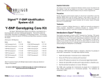
1
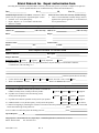
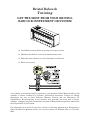
EXPANSION COMMUNICATIONS
PORT RS-232 BOARD
Part No. 392970-01-5
(For Models 3530-XXX)
For The Following BBI Instruction Manuals:
CI-3530-10B, CI-3530-15B, CI-3530-20B, CI-3530-25B,
CI-3530-35B, CI-3530-40B, CI-3530-45B & CI-3530-50B
Bristol Babcock
Product Information Package
PIP-EXP232TF – December, 2003
NOTICE
Copyright Notice
The information in this document is subject to change without notice. Every effort has been
made to supply complete and accurate information. However, Bristol Babcock assumes no
responsibility for any errors that may appear in this document.
Request for Additional Instructions
Additional copies of instruction manuals may be ordered from the address below per
attention of the Sales Order Processing Department. List the instruction book numbers or
give complete model number, serial or software version number. Furnish a return address
that includes the name of the person who will receive the material. Billing for extra copies
will be according to current pricing schedules.
TeleFlowTM, TeleRTUTM and TeleRecorderTM are trademarks of Bristol Babcock. Other
trademarks or copy-righted products mentioned in this document are for information only,
and belong to their respective companies, or trademark holders.
Copyright (c) 2003 Bristol Babcock, 1100 Buckingham St., Watertown, CT 06795. No part of
this manual may be reproduced in any form without the express written permission of
Bristol Babcock.
IMPORTANT! READ INSTRUCTIONS BEFORE STARTING!
Be sure that these instructions are carefully read and understood before any
operation is attempted. Improper use of this device in some applications may result
in damage or injury. The user is urged to keep this book filed in a convenient location
for future reference.
These instructions may not cover all details or variations in equipment or cover
every possible situation to be met in connection with installation, operation or
maintenance. Should problems arise that are not covered sufficiently in the text, the
purchaser is advised to contact Bristol Babcock for further information.
EQUIPMENT APPLICATION WARNING
The customer should note that a failure of this instrument or system, for
whatever reason, may leave an operating process without protection. Depending
upon the application, this could result in possible damage to property or injury to
persons. It is suggested that the purchaser review the need for additional backup
equipment or provide alternate means of protection such as alarm devices, output
limiting, fail-safe valves, relief valves, emergency shutoffs, emergency switches, etc.
If additional information is required, the purchaser is advised to contact Bristol
Babcock.
RETURNED EQUIPMENT WARNING
When returning any equipment to Bristol Babcock for repairs or evaluation,
please note the following: The party sending such materials is responsible to ensure
that the materials returned to Bristol Babcock are clean to safe levels, as such levels
are defined and/or determined by applicable federal, state and/or local law regulations
or codes. Such party agrees to indemnify Bristol Babcock and save Bristol Babcock
harmless from any liability or damage which Bristol Babcock may incur or suffer due
to such party’s failure to so act.
ELECTRICAL GROUNDING
Metal enclosures and exposed metal parts of electrical instruments must be
grounded in accordance with OSHA rules and regulations pertaining to "Design
Safety Standards for Electrical Systems," 29 CFR, Part 1910, Subpart S, dated: April
16, 1981 (OSHA rulings are in agreement with the National Electrical Code).
The grounding requirement is also applicable to mechanical or pneumatic
instruments that include electrically-operated devices such as lights, switches, relays,
alarms, or chart drives.
EQUIPMENT DAMAGE FROM ELECTROSTATIC DISCHARGE VOLTAGE
This product contains sensitive electronic components that can be damaged by
exposure to an electrostatic discharge (ESD) voltage. Depending on the magnitude
and duration of the ESD, this can result in erratic operation or complete failure of the
equipment. Read BBI supplemental document S14006 for proper care and handling
of ESD-sensitive components.
Bristol Babcock 1100 Buckingham Street, Watertown, CT 06795
Telephone (860) 945-2200
WARRANTY
A.
Bristol warrants that goods described herein and manufactured by Bristol are free
from defects in material and workmanship for one year from the date of shipment
unless otherwise agreed to by Bristol in writing.
B.
Bristol warrants that goods repaired by it pursuant to the warranty are free from
defects in material and workmanship for a period to the end of the original warranty
or ninety (90) days from the date of delivery of repaired goods, whichever is longer.
C.
Warranties on goods sold by, but not manufactured by Bristol are expressly limited
to the terms of the warranties given by the manufacturer of such goods.
D.
All warranties are terminated in the event that the goods or systems or any part
thereof are (i) misused, abused or otherwise damaged, (ii) repaired, altered or
modified without Bristol’s consent, (iii) not installed, maintained and operated in
strict compliance with instructions furnished by Bristol, or (iv) worn, injured or
damaged from abnormal or abusive use in service time.
E.
THESE WARRANTIES ARE EXPRESSLY IN LIEU OF ALL OTHER
WARRANTIES EXPRESS OR IMPLIED (INCLUDING WITHOUT LIMITATION
WARRANTIES AS TO MERCHANTABILITY AND FITNESS FOR A PARTICULAR
PURPOSE), AND NO WARRANTIES, EXPRESS OR IMPLIED, NOR ANY
REPRESENTATIONS, PROMISES, OR STATEMENTS HAVE BEEN MADE BY
BRISTOL UNLESS ENDORSED HEREIN IN WRITING. FURTHER, THERE ARE
NO WARRANTIES WHICH EXTEND BEYOND THE DESCRIPTION OF THE
FACE HEREOF.
F.
No agent of Bristol is authorized to assume any liability for it or to make any written
or oral warranties beyond those set forth herein.
REMEDIES
A.
Buyer’s sole remedy for breach of any warranty is limited exclusively to repair or
replacement without cost to Buyer of any goods or parts found by Seller to be
defective if Buyer notifies Bristol in writing of the alleged defect within ten (10) days
of discovery of the alleged defect and within the warranty period stated above, and if
the Buyer returns such goods to Bristol’s Watertown office, unless Bristol’s Watertown office designates a different location, transportation prepaid, within thirty (30)
days of the sending of such notification and which upon examination by Bristol
proves to be defective in material and workmanship. Bristol is not responsible for
any costs of removal, dismantling or reinstallation of allegedly defective or defective
goods. If a Buyer does not wish to ship the product back to Bristol, the Buyer can
arrange to have a Bristol service person come to the site. The Service person’s
transportation time and expenses will be for the account of the Buyer. However,
labor for warranty work during normal working hours is not chargeable.
B.
Under no circumstances will Bristol be liable for incidental or consequential damages
resulting from breach of any agreement relating to items included in this quotation
from use of the information herein or from the purchase or use by Buyer, its
employees or other parties of goods sold under said agreement.
How to return material for Repair or Exchange
Before a product can be returned to Bristol Babcock for repair, upgrade, exchange, or to
verify proper operation, form (GBU 13.01) must be completed in order to obtain a RA
(Return Authorization) number and thus ensure an optimal lead time. Completing the form
is very important since the information permits the Bristol Babcock Repair Dept. to
effectively and efficiently process the repair order.
You can easily obtain a RA number by:
A. FAX
Completing the form (GBU 13.01) and faxing it to (860) 945-3875. A BBI Repair
Dept. representative will return call (or other requested method) with a RA number.
B. E-MAIL
Accessing the form (GBU 13.01) via the Bristol Babcock Web site
(www.bristolbabcock.com) and sending it via E-Mail to [email protected].
A BBI Repair Dept. representative will return E-Mail (or other requested method)
with a RA number.
C. Mail
Mail the form (GBU 13.01) to
Bristol Babcock Inc.
Repair Dept.
1100 Buckingham Street
Watertown, CT 06795
A BBI Repair Dept. representative will return call (or other requested method) with
a RA number.
D. Phone
Calling the BBI Repair Department at (860) 945-2442. A BBI Repair Department
representative will record a RA number on the form and complete Part I, then send
the form to the Customer via fax (or other requested method) for Customer
completion of Parts II & III.
A copy of the completed Repair Authorization Form with issued RA number should be included with the product being returned. This will allow us to quickly track, repair, and
return your product to you.
&VMWXSP&EFGSGO-RG6ITEMV%YXLSVM^EXMSR*SVQ
(Providing this information will permit BBI to effectively and efficiently process your return. Completion is required to
receive optimal lead time. Lack of information may result in increased lead times.)
Date___________________
RA #___________________SH_
Standard Repair Practice is as follows: Variations to this is
practice may be requested in the “Special Requests” section.
• Evaluate / Test / Verify Discrepancy
• Repair / Replace / etc. in accordance with this form
• Return to Customer
Part I
Line No.____________
Please be aware of the Non warranty standard charge:
• There is a $100 minimum evaluation charge, which is
applied to the repair if applicable (√ in “returned” B,C,
or D of part III below)
Please complete the following information for single unit or multiple unit returns
Address No.
(office use only) Address No.
(office use only)
Bill to :
Ship to:
Purchase Order:
Contact Name:____________________________________
Phone:
Fax:
Part II
E-Mail:
Please complete Parts II & III for each unit returned
Model No./Part No.
Description
Range/Calibration
S/N
Reason for return :
1.
Failure
Upgrade
Verify Operation
Other
Describe the conditions of the failure (Frequency/Intermittent, Physical Damage, Environmental Conditions,
Communication, CPU watchdog, etc.)
(Attach a separate sheet if necessary)
2.
Comm. interface used:
3.
What is the Firmware revision? _____________________
Standalone
RS-485
Ethernet
Other:______________
Modem (PLM (2W or 4W) or SNW)
What is the Software &version?
Part III If checking “replaced” for any question below, check an alternate option if replacement is not available
A. If product is within the warranty time period but is excluded due
to BBI’s warranty clause, would you like the product:
repaired
returned
replaced
scrapped?
B. If product were found to exceed the warranty period,
would you like the product:
repaired
returned
replaced
scrapped?
C. If product is deemed not repairable would you like your product:
returned
replaced
scrapped?
D. If BBI is unable to verify the discrepancy, would you like the product:
returned
replaced
*see below?
* Continue investigating by contacting the customer to learn more about the problem experienced? The person to contact that
has the most knowledge of the problem is:
_______________________________ phone
If we are unable to contact this person the backup person is: _________________________ phone
Special Requests:
Ship prepaid to: Bristol Babcock Inc., Repair Dept., 1100 Buckingham Street, Watertown, CT 06795
Phone: 860-945-2442
Fax: 860-945-3875
Form GBU 13.01
Rev. A
Bristol Babcock
Training
GET THE MOST FROM YOUR BRISTOL
BABCOCK INSTRUMENT OR SYSTEM
● Avoid Delays and problems in getting your system on-line
● Minimize installation, start-up and maintenance costs.
● Make the most effective use of our hardware and software.
● Know your system.
As you know, a well-trained staff is essential to your operation. Bristol Babcock offers a full
schedule of classes conducted by full-time, professional instructors. Classes are offered
throughout the year at three locations: Houston, Orlando and our Watertown, CT
headquarters. By participating in our training, your personnel can learn how to install,
calibrate, configure, program and maintain any and all Bristol Babcock products and realize
the full potential of your system.
For information or to enroll in any class, contact our training department in Watertown at
(860) 945-2269. For Houston classes, you can also contact our Houston office, at (713) 6856200.
A Few Words About Bristol Babcock
For over 100 years, Bristol7 has been providing innovative solutions for the measurement
and control industry. Our product lines range from simple analog chart recorders, to
sophisticated digital remote process controllers and flow computers, all the way to turnkey
SCADA systems. Over the years, we have become a leading supplier to the electronic gas
measurement, water purification, and wastewater treatment industries.
On off-shore oil platforms, on natural gas pipelines, and maybe even at your local water
company, there are Bristol Babcock instruments, controllers, and systems running year-in
and year-out to provide accurate and timely data to our customers.
Getting Additional Information
In addition to the information contained in this manual, you may receive additional assistance in using this product from the following sources:
Contacting Bristol Babcock Directly
Bristol Babcock's world headquarters are located at 1100 Buckingham Street, Watertown,
Connecticut 06795, U.S.A.
Our main phone numbers are:
(860) 945-2200
(860) 945-2213 (FAX)
Regular office hours are Monday through Friday, 8:00AM to 4:30PM Eastern Time,
excluding holidays and scheduled factory shutdowns. During other hours, callers may leave
messages using Bristol's voice mail system.
Telephone Support - Technical Questions
During regular business hours, Bristol Babcock's Application Support Group can provide
telephone support for your technical questions.
For technical questions about TeleFlowÔ products call (860) 945-8604.
For technical questions about ControlWave call (860) 945-2244 or (860) 945-2286.
For technical questions regarding Bristol’s OpenEnterprise product, call (860) 945-3865 or
e-mail: [email protected]
For technical questions regarding ACCOL products, Open BSI Utilities, as well as
Bristol's Enterprise Server7/Enterprise Workstation7 products, call (860) 945-2286.
For technical questions about Network 3000 hardware, call (860) 945-2502.
You can e-mail the Application Support Group at: [email protected]
The Application Support Group maintains an area on our web site for software updates and
technical information. Go to: www.bristolbabcock.com/services/techsupport/
For assistance in interfacing Bristol Babcock hardware to radios, contact Bristol Babcock’s
Communication Technology Group in Orlando, FL at (407) 629-9463 or (407) 6299464.
Telephone Support - Non-Technical Questions, Product Orders, etc.
Questions of a non-technical nature (product orders, literature requests, price and delivery
information, etc.) should be directed to the nearest sales office (listed on the rear cover) or to
your Bristol-authorized sales representative.
Please call the main Bristol Babcock number (860-945-2200) if you are unsure which office
covers your particular area.
Visit our Site on the World Wide Web
For general information about Bristol Babcock and its products, please visit our site on the
World Wide Web at: www.bristolbabcock.com
Training Courses
Bristol Babcock’s Training Department offers a wide variety of courses in Bristol hardware
and software at our Watertown, Connecticut headquarters, and at selected Bristol regional
offices, throughout the year. Contact our Training Department at (860) 945-2269 for course
information, enrollment, pricing, and scheduling.
PIP-EXP232TF
EXPANSION COMMUNICATIONS PORT
RS-232 BOARD
PT. Number 392970-01-5
Product Information Package
TABLE OF CONTENTS
SECTION
TITLE
PAGE #
Section 1 - INTRODUCTION
1.1
1.1.1
1.1.2
1.2
1.3
1.3.1
DESCRIPTION................................................................................................................... 1
Function .............................................................................................................................. 1
Features............................................................................................................................... 2
COMPONENT IDENTIFICATION................................................................................... 2
INSTALLATION COMPATIBILITY................................................................................ 2
Restrictions ......................................................................................................................... 2
Section 2 - INSTALLATION & SERVICE
2.1
2.1.1
2.1.1.1
2.1.1.2
2.1.1.3
2.2
EXPCOM232 REMOVAL/REPLACEMENT & INSTALLATION................................. 3
Installation/Removal of the EXPCOM232 Board .............................................................. 3
Installation/Removal for Models 3530-10B, -15B, -40B, -45B & -50B ............................ 3
Installation/Removal for Models 3530-20B & -25B ........................................................ 10
Installation/Removal for Models 3530-35B ..................................................................... 11
RS-232 WIRING............................................................................................................... 12
Section 3 - SPECIFICATIONS
3.1
3.2
PERFORMANCE SPECIFICATIONS ............................................................................ 15
ENVIRONMENTAL SPECIFICATIONS ....................................................................... 15
SUPPLEMENTS
Special Instructions for Class I, Division 2 Hazardous Locations ..............................................Appendix A
Special Instructions for Class I, Division 1 Hazardous Locations ..............................................Appendix B
PIP-EXP232TF
Page 0-1
Table Of Contents
Section 1
INTRODUCTION
1.1 DESCRIPTION
1.1.1 Function
The Expansion Communications Port RS-232 Board (EXPCOM232) provides a single RS232 asynchronous serial communications port to ACCOL-based 3530-XXX models. In
addition to assignments of the resident (host) CPU’s “local” and “network” RS-232 ports,
any model 3530-XXX unit equipped with an EXPCOM232 Board can establish RS-232
communications with an external device. An EXPCOM232 Board plugs into the Expansion
Connector of the TeleFlow or TeleRTU CPU Board and is stood-off by three 15/32” long hex
standoffs and is secured via three screws. The CPU Board Expansion Connector supplies
power and 3530-XXX communication to the EXPCOM232 Board.
EXPCOM232 Boards measure 4.0” by 3.75” and utilizes a 7-position Industrial 3.5mm pitch
plugable connector to interface with an external RS-232 device. 16V bi-directional
Transient Absorption Zener Diodes are placed across all RS-232 outputs.
Programmable baud rates up to 19.2Kbps are supported by the EXPCOM232 Board. TXD,
RXD, RTS, CTS, DTR, CD and GND (RS-232) signals are available at TB1 of the
EXPCOM232 Board. CD (Carrier Detect) (supplied by a DCE attempting to communicate
with a model 3530-XXX), will awaken the 3530-XXX CPU Board. If no activity is required,
the EXPCOM232 Board‘s serial communications controller (SCC) chip and RS-232 drivers
can be put to sleep (low power mode) along with the host/parent 3530-XXX.
Figure 1 - Expansion Communications Port RS-232 Board
PIP-EXP232TF
Page 1
EXPCOM232 Option
1.1.2 Features
·
Low Power
+5V @ 20mA (Max) regulated power is supplied by the host/parent 3530-XXX via the
40-pin Expansion Interface Connector P1.
·
ESD & Transient Susceptibility
The RS-232 I/O circuitry has been designed to meet the requirements of IEC 801-2
for ESD withstand capability up to 10KV and the requirements of ANSI/IEEE
C37.90.1-1989 (formerly IEE 472) for surge withstand capability.
·
EMI Compatibility
EXPCOM232 Boards have been designed to coexist inside a shielded enclosure with
the TeleFlowä electronics. EMI radiation is insignificant and susceptibility is
comparable or superior to associated electronics.
·
Mounting
The EXPCOM232 Board measures 3.75” (9.525cm) in width x 4.0” (10.160cm) in
height and mounts piggy-back on a TeleFlow or TeleRTU CPU Board.
·
RS-232 Serial Port
EXPCOM232 Boards provide an additional RS-232 serial port that is programmable
for rates up to 19.2Kbps. 3530-XXX units equipped with the EXPCOM232 Board can
communicate with a local RS-232 device even though a radio or modem may be
installed on the CPU Board’s network port.
1.2 COMPONENT IDENTIFICATION
EXPCOM232 Boards do not contain LEDs, switches or configuration jumpers. Two connectors are provided; 40-pin connector P1 mates with the host 3530-XX-X (connector J4 TeleFlow CPU or J18 - TeleRTU CPU) and accommodates the TTL interface between the
two entities, while 7-pin connector TB1 mates with the RS-232 device that is being
interfaced to the 3530-XXX. Additionally, the 3.5mm pitch plugable connector TB1 is
removable from its mating EXPCOM232 Board socket.
1.3 INSTALLATION COMPATIBILITY
An EXPCOM232 Board can be installed into any of the following 3530-XXX models:
3530-10B - TeleFlow
3530-15B - TeleRTU
3530-20B - TeleFlow Plus
3530-25B - TeleRTU Plus
3530-35B - TeleRTU Module
3530-40B - TeleFlow ECR
3530-45B - TeleRecorder
3530-50B - TeleFlow Corrector
1.3.1 Restrictions
The 3530-XXX in question must be equipped with ACCOL application software. 3530-XXX
units support installation of only one optional piggyback mounted Expansion Board (I/O,
Comm. or TIB).
EXPCOM232 Option
Page 2
PIP-EXP232TF
Section 2
INSTALLATION & SERVICE
2.1 EXPCOM232 REMOVAL/REPLACEMENT & INSTALLATION
2.1.1 Installation/Removal of the EXPCOM232 Board
In addition to hardware normally contained within the 3530-XXX in question, units with an
installed EXPCOM232 Option will contain the following major parts.
1. Expanded Communications Port RS-232 Board (EXPCOM232)
2. Three #4-40 x 15/32” Standoffs (Note: Models 3530-10B, - 15B, -40B, -45B & -50B will
also contain Three (3) #4-40 x .188” Standoffs & Two (2) #4-40 x 1/8” SEM Screws)
3. Modified PC Shield Assembly (for models 3530-10B, -15B, -40B, -45B & -50B)
WARNING
Never attempt to service a TeleFlow, TeleRTU,
TeleRecorder or TeleFlow Corrector while it is powered
and operating in a hazardous environment. Either the
area must be made safe or the unit must be powered
down, unwired, unmounted, and taken to a safe, nonhazardous area.
WARNING
Never attempt to install or remove any components
(PCBs, Field Wiring, Transducers, etc.) while the unit is
powered and running. Doing so can cause sudden
electrical transients or imbalances that are capable of
causing damage to the module or component in question,
as well as other associated circuit boards. Always turn
off the external/internal power source, including any
additional supply sources used for externally-powered
I/O circuits, before changing or adding any components.
CAUTION
Place any related critical processes under manual or
auxiliary control prior to shutting down or performing
any of the steps discussed herein.
2.1.1.1 Installation/Removal for Models 3530-10B, -15B, -40B, -45B & -50B
To install the optional EXPCOM232 Board into a model 3530-10B, -15B, -40B, -45B or 50B, follow steps 1 through 14 below. To remove the optional EXPCOM232 Board, see step
15. Note: The Instrument Front Cover must be open.
1. To open the Instrument Front Cover, remove the lock if present and turn each of the
three captive screws a quarter (1/4) turn counterclockwise.
PIP-EXP232TF
Page 3
EXPCOM232 Option
Note:
The CPU Board is not to be removed under any
circumstances unless the unit has been moved to an ESD
safe area (see ESDS Manual - S14006).
2. Remove the Power Plug(s), Solar Panel Power Plug, and the Auxiliary Power Plug as
required, from the CPU Board in question.
3. Remove the optional radio or modem if installed.
To remove an optional modem:
Disconnect the phone wires. Loosen the four (4) screws that secure the Modem/Radio
Mounting Plate (with modem) to the Battery Mounting Bracket. Slide the modem to
the left and remove it and then disconnect the D-Type connector from the modem.
To remove an optional radio:
Disconnect the Radio/TeleFlow Interface Cable from the bottom of the Radio. Unplug
the 2-wire power connector associated with the 2-wire Radio Power Interface Cable
from the bottom of the Radio. Loosen the four (4) screws that secure the Modem/Radio
Mounting Plate (with radio) to the Battery Mounting Bracket. Slide the radio to the
left and remove it.
4. Remove the Battery(s) (if present).
To remove the battery(s) from units without an optional modem or radio:
Hold the battery securely and remove the Left Battery Mounting Bracket (secured
with 2 screws. Loosen the screws which secure the Right Battery Mounting Bracket
(Carefully remove the battery (with wiring harness). Remove the Right Battery
Mounting Bracket.
To remove the battery(s) from units with an optional modem or radio:
Carefully remove the battery (with wiring harness). Note: You may have to loosen the
two left 1/4-20 x 3/8” screws that secure the left side of the Battery Mounting Bracket
and the Main Mounting Bracket to the rear of the unit. While holding the Main
Mounting Bracket, remove the four (4) 1/4-20 x 3/8” screws and lock washers that
secure the Battery Mounting Bracket and Main Mounting Bracket to the rear of the
unit. Remove the Battery Mounting Bracket and temporarily reinstall the four screws
to secure the Main Mounting Bracket to the 3530-10B, 15B, -45B or -50B.
5. Disconnect the Local Port, Network Port, RTD, and Field I/O wires from the CPU Bd.
connectors by unplugging their associated Term. Plugs on the front edge of the CPU.
6. Carefully remove the PC Shield which is secured to the Main Mounting Bracket by 2
(#4-40 x 1/4”) screws and to the CPU Board by 2 (#4-40 x 1/4”) screws.
7. Remove the screw (location ‘A’ in Figures 2 & 3) and the two (2) #4-40 x 5/8” Standoffs
(location ‘B’ in Figures 2 & 3) which secure the CPU Board to the Main Mounting
Bracket. Replace these items with the three new #4-40 x 15/32” Standoffs.
Note:
This operation should only be performed in an ESD safe area.
8. Align the EXPCOM232 Board Connector P1 with CPU Board Connector J4 (for 353010B, 40B or -50B) or J18 (for 3530-15B & -45B). Push the EXPCOM232 Board toward
the CPU Board until Connector P1 is fully seated.
EXPCOM232 Option
Page 4
PIP-EXP232TF
Figure 2 - TeleFlow CPU Board – Installation Drawing #1
9. Secure the EXPCOM232 Board to the CPU Board by installing three (3) #4-40 x .188”
Standoffs at locations ‘A’ and ‘B’ (see Figures 2 & 3).
10. Carefully install the Modified PC Shield, securing it to the Main Mounting Bracket (at
locations ‘C’) with two #4-40 x 1/4” screws and to the CPU Board (at locations ‘B’) with
two (2) #4-40 x 1/8” SEM screws (see Figures 4, 5, 6 & 7).
11. Follow steps 2 through 6 in reverse order, replacing rather than removing the item in
question.
PIP-EXP232TF
Page 5
EXPCOM232 Option
12. Connect wiring between the EXPCOM232 Board and the DTE/DCE device to which it
is to be interfaced (see Section 2.2).
13. Configure the new network port in the ACCOL Load resident in the host 3530-XXX
device.
Figure 3 - TeleRTU CPU Board – Installation Drawing #1
14. Close and secure the Instrument Front Cover.
15. To remove an optional EXPCOM232 Board, follow steps 1 through 6 (unplug the RS232 cable during step 5). Remove the PC Shield along with the three Standoffs that
EXPCOM232 Option
Page 6
PIP-EXP232TF
secure the EXPCOM232 Board to the CPU Board. Then unplug the EXPCOM232
Board from the CPU Board in question.
Figure 4 - TeleFlow CPU Board (with EXPCOM232 Installed)
Installation Drawing #2
PIP-EXP232TF
Page 7
EXPCOM232 Option
Figure 5 - TeleRTU CPU Board (with EXPCOM232 Installed)
Installation Drawing #2
EXPCOM232 Option
Page 8
PIP-EXP232TF
Figure 6 - 3530-10B, 3530-40B & 3530-50B (with EXPCOM232 Installed)
Figure 7 - 3530-15B & 3530-45B (with EXPCOM232 Installed)
PIP-EXP232TF
Page 9
EXPCOM232 Option
2.1.1.2 Installation/Removal for Models 3530-20B & -25B
To install the optional EXPCOM232 Board into a model 3530-20B or 3530-25B, follow steps
1 through 11 below. To remove the optional EXPCOM232 Board, perform steps 1 and 2 and
then follow steps 4 through 9 in reverse order, removing rather than installing the item in
question after the system has been shut down. Note: The Instrument Front Cover must be
open.
1. Open the Instrument Front Cover
2. Disconnect power by removing harness connector plug (P8 for TeleFlow - P2 for
TeleRTU) from the CPU Board edge connector (J8 for TeleFlow – J2 for TeleRTU).
Figure 8 - 3530-20B CPU (with EXPCOM232 Installed)
3. Unplug the remaining removable Terminal Blocks (with wiring harnesses installed)
from the CPU Board’s front edge connectors.
4. Remove the two screws that secure the CPU Board’s Sliding Mounting Bracket to the
Fixed Bracket on the bottom of the Battery Bracket. Carefully slide the CPU Board
(and optional EXPCOM232 Board) toward the front of the unit. Remove harness
connections from the Front Panel Switch (J12 on the TeleFlow CPU - J14 on TeleRTU
CPU), the Display Module (J2 on TeleFlow CPU - J16 on TeleRTU CPU), the Wakeup
Switch (J3 on TeleFlow CPU - J16 on TeleRTU CPU), and for TeleFlow CPU Boards
connector J1 (associated with the Multivariable Transducer).
5. Remove the three screws (of five) that secure the CPU Board to the Sliding Mounting
Bracket (locations ‘A’ & ‘B’ in Figures 2 & 3) and replace these items with the three
new #4-40 x 15/32” Standoffs.
Note:
This operation should only be performed in an ESD safe area.
6. Align the EXPCOM232 Board Connector P1 with CPU Board Connector J4 (for 353020B) or J18 (for 3530-25B). Push the EXPCOM232 Board toward the CPU Board until
Connector P1 is fully seated.
7. Secure the EXPCOM232 Board to the CPU Board by installing three (3) #4-40 x 1/4”
SEM screws as illustrated in Figures 8 & 9.
EXPCOM232 Option
Page 10
PIP-EXP232TF
Figure 9 - 3530-25B CPU (with EXPCOM232 Installed)
8. Route the RS-232 cable through a ¾” conduit fitting (user installed) on the bottom of
the enclosure.
9. Connect wiring between the EXPCOM232 Board and the DTE/DCE device to which it
is to be interfaced (see Section 2.2).
10. Configure the new network port in the ACCOL Load resident in the host 3530-XXX
device.
11. Close and secure the Instrument Front Cover.
2.1.1.3 Installation/Removal for Models 3530-35B
To install the optional EXPCOM232 Board into a model 3530-35B, follow steps 1 through 8
below. To remove the optional EXPCOM232 Board, perform step 1 and then follow steps 5
through 7 in reverse order, removing rather than installing the item in question after the
system has been shut down.
1. Disconnect power by removing harness connector plug P2 from the CPU Board edge
connector J2.
2. Unplug the remaining removable Terminal Blocks (with wiring harnesses installed)
from the CPU Board’s front edge connectors.
3. Remove harness connections from the Front Panel Switch (J14), the Display Module
(J16) and the Wakeup Switch (J16).
4. Remove the three screws (of five) that secure the CPU Board to the RTU Mounting
Bracket (locations ‘A’ & ‘B’ in Figures 2 & 3) and replace these items with the three
new #4-40 x 15/32” Standoffs.
Note:
This operation should only be performed in an ESD safe area.
5. Align the EXPCOM232 Board Connector P1 with CPU Board Connector J18. Push the
EXPCOM232 Board toward the CPU Board until Connector P1 is fully seated.
PIP-EXP232TF
Page 11
EXPCOM232 Option
6. Secure the EXPCOM232 Board to the CPU Board by installing three (3) #4-40 x 1/4”
SEM screws as illustrated in Figure 10.
7. Connect wiring between the EXPCOM232 Board and the DTE/DCE device to which it
is to be interfaced (see Section 2.2).
8. Configure the new network port in the ACCOL Load resident in the host 3530-XXX
device.
Figure 10 - 3530-35B (with EXPCOM232 Installed)
2.2 RS-232 WIRING
Table 2-1 and Figure 11 must be referenced to configure the RS-232 cable. Pin 2 of TB1 =
DCD (Data Carrier Detect - DCD). DCD can be used to awaken the 3530-XXX in question
from power conservation (sleep) mode. This signal is not supplied by DTE equipment.
EXPCOM232 Option
Page 12
PIP-EXP232TF
Figure 11 - EXPCOM232 Wiring Diagrams
PIP-EXP232TF
Page 13
EXPCOM232 Option
Either an RS-232 level control signal (high) can be supplied to TB1-2, or TB1-2 may be
connected to the EXC signal on the CPU Board. It must be noted that as long as TB1-2
(DCD) remains HIGH, the 3530-XXX in question will remain awake. Therefore, if TB1-2 is
connected to an EXC signal on the resident CPU Board, power conservation will be
defeated, thus reducing the battery back-up time.
RS-232 cables are typically short (20’ or less in length). When significant distances are a
factor (i.e., between an EXPCOM232 Board and the remote Data Terminal Device (DTE) to
which it is desired to communicate), the RS-232 Port (TB1) cable can be connected to the
RS-232 Port of a modem or that of a BBI Isolated RS-485 Board (see Table 2-1).
Table 2-1
EXPCOM232 Board (DTE) & DCE/DTE - RS-232 Port Pin Assignments
EXPCOM232
RS-232 – TB1
EXPCOM232
RS-232 TB1 or
3530 Network
Modem
9-Pin – J4
PC
(RS-232)
DCE
1 - DCD (Out)
2 - RXD (Out)
3 - TXD (In)
4 - DTR (In)
5 - GND
6 - DSR (Out)
7 - RTS (In)
8 - CTS (Out)
9 - N/A
DTE
3 - TXD (Out)
2 - RXD (In)
5 - GND
8 - CTS (In)
7 - RTS (Out)
-
Port J13/J8
DTE
2 - DCD (In)
6 - RXD (In)
7 - TXD (Out)
3 - DTR (Out)
1 - GND
5 - RTS (Out)
4 - CTS (In)
-
DTE
7 - TXD (Out)
6 - RXD (In)
1 - GND
4 - CTS (In)
5 - RTS (Out)
-
3310/30/35
3305
3332
Notes 1 & 2
DTE
2 - TXD (Out)
4 - RXD (In)
9 - GND
6 - CTS (In)
5 - RTS (Out)
-
BBI
Isolated RS-485
Board Option
J1
DTE
7 - TXD (Out)
6 - RXD (In)
1 - GND
4 - CTS (In)
5 - RTS (Out)
-
Note 1: Ports BIP1 & BIP2
BIP1 and BIP2 are RS-562 Ports (RS-232 compatible.
Note 2: 3310 Ports A & C (MFIB Board)
A & C are RS-423 Ports (RS-232 compatible).
3330 Ports A, B, C, D, G, H, I & J (Enhanced Comm. Boards)
ECB’s 392587-01-7, 392587-02-5, 392587-03-3 & 392903-01-6
A, B, C, D, G, H, I & J are RS-562 Ports (RS-232 compatible).
3335 Ports A, B, C, D, I & J (Enhanced Comm. Boards)
ECB’s 392589-01-0 & 392589-02-8
A, B, C, D, I & J are RS-232 Ports
3335 Ports A, B, C & D (Comm. Engine Boards)
CEB’s 392043-01-7 & 392058-01-4
A, B, C & D are RS-423 Ports (RS-232 compatible)
The device uses compression-type terminals that accommodate up to #14 AWG wire. A
connection is made by inserting the bared end (1/4 inch Max.) into the clamp beneath the
screw and then securing the screw. Insert the bared end fully to prevent short circuits.
Allow some slack in the wires when making terminal connections. The slack makes the
connections more manageable and minimizes mechanical strain on the printed circuit
boards and harnesses.
EXPCOM232 Option
Page 14
PIP-EXP232TF
Section 3
SPECIFICATIONS
3.1 PERFORMANCE SPECIFICATIONS
Baud Rate (Max.):
19.2K Asynchronous
Power Requirements:
+5Vdc @ 20mA Max. (Regulated)
Transient Protection:
16V Bi-directional Transient Absorption Zeners across all
RS-232 outputs
RS-232 Outputs:
TXD (TB1-7)
DTR (TB1-3)
RTS (TB1-5)
RS-232 Inputs:
DCD (TB1-2)
RXD (TB1-6)
CTS (TB1-4)
RS-232 Ground:
GND (TB1-1)
RS-232 Interface Connector:
7-Pin Industrial 3.5mm Pitch Plugable Connector
3.2 ENVIRONMENTAL SPECIFICATIONS
Operating Temperature:
-40° to +60° (C) [-40° to 140° (F)]
Storage Temperature:
-40° to +85° (C) [-40° to 185° (F)]
Humidity:
15% to 90% RH (Non-Condensing)
ESD Susceptibility:
Meets the requirement of IEC 801-2 for ESD withstand
Capability up to 10KV.
EMI Compatibility:
Designed to coexist inside a shielded enclosure with the
TeleFlow electronics. EMI radiation is insignificant and
Susceptibility is comparable or superior to associated
Electronics.
Transient Susceptibility:
Designed to meet the requirements of ANSI/IEEE
C37.90.1-1989 (Formerly IEEE 472) for surge withstand
Capability.
PIP-EXP232TF
Page 15
EXPCOM232 Option
Expansion Communications Port RS-232 Board
Special Instructions for Class I, Division 2 Hazardous Locations
1. The BBI Expansion Communications Port RS-232 Board is listed by Underwriters
Laboratories (UL) as nonincendive and is suitable for use in Class I, Division 2, Groups
A, B, C and D hazardous locations or non-hazardous locations only. Read this document
carefully before installing a nonincendive BBI Expansion Communications Port RS-232
Board. In the event of a conflict between the Expansion Communications Port RS-232
Board User Manual (PIP-EXP232TF) and this document, always follow the instructions
in this document.
2. Wiring must be performed in accordance with Class I, Division 2 wiring methods as
defined in Article 501-4 (b) of the National Electrical Code, NFPA 70 for installations
within the United States, or as specified in Section 18-152 of the Canadian Electrical
Code for installation in Canada.
3. WARNING: EXPLOSION HAZARD - Substitution of components may impair
suitability for use in Class I, Division 2 environments.
4. WARNING: EXPLOSION HAZARD - When situated in a hazardous location,
turn off power before servicing/replacing the unit and before installing or
removing I/O wiring.
5. WARNING: EXPLOSION HAZARD - Do Not disconnect equipment unless the
power has been switched off or the area is known to be nonhazardous.
07/17/2000
Appendix A of PIP-EXP232TF - EXPCOM232 Board
Page 1 of 1
Expansion Communications Port RS-232 Board for 3530-XXX
Special Instructions for Class I, Division 1 Hazardous Locations
1. A version of the Expansion Communications Port RS-232 Board is available that is
listed by Underwriters Laboratories (UL) as intrinsically safe for use in Class I, Division
1, Groups C and D hazardous locations. Read this document carefully before installing
an intrinsically safe Expansion Communications Port RS-232 Board. Refer to the
Expansion Communications Port RS-232 Board User’s Manual (PIP-EXP232TF) for
general information. In the event of a conflict between the Expansion Communications
Port RS-232 Board User’s Manual and this document, always follow the instructions in
this document.
2. Unless the Expansion Communications Port RS-232 Board is used in conjunction with
an IStran Communications Interface Assembly (see CI-3530-Istran) it may not be used
in a Class I, Division 1 hazardous location.
3. When a TeleFlow equipped with an Expansion Communications Port RS-232 Board is
used in a Class I, Division 1 location, it must be used in conjunction with a BBI IStran
Communications Interface and installed per instruction manual CI-3530-IStran and
PIP-EXP232TF.
4. The IStran and Expansion Communications Port RS-232 Board can be located in a
nonhazardous or Division 2 rated area, while the TeleFlow can reside in a Division 1, 2
or nonhazardous area.
A suitable enclosure must be provided for the IStran. When the IStran is mounted in a
Division 2 area, the nonhazardous interface connections shall be made in accordance
with Article 501-4(b) of the National Electrical Code NFPA 70.
CAUTION
When connecting the IStran and Expansion Communications
Port RS-232 Board to a TeleFlow that is mounted in a Division
1 area, wire all circuits using wiring methods specified in
article 504 of the National Electrical Code NFPA 70. Contact
your IStran supplier for assistance.
When installing an Expansion Communications Port RS-232
Board in a TeleFlow that is mounted in a Division 2 area,
ensure that the area is nonhazardous before connecting or
disconnecting the nonhazardous interface.
5. Figures B1 through B4 show variations of approved connections to the Expansion
Communications Port RS-232 Board via a BBI IStran Communications Interface
Assembly.
12/12/03
Appendix B - Document PIP-EXP232TF
Page 1 of 3
Expansion Communications Port RS-232 Board for 3530-XXX
Special Instructions for Class I, Division 1 Hazardous Locations
Figure B1 - Intrinsically Safe System with Radio and EXPCOM232 Board
(with Single Power Source)
Figure B2 - Intrinsically Safe System with Modem and EXPCOM232 Board
(with Single Power Source)
12/12/03
Appendix B - Document PIP-EXP232TF
Page 2 of 3
Expansion Communications Port RS-232 Board for 3530-XXX
Special Instructions for Class I, Division 1 Hazardous Locations
Figure B3 - Intrinsically Safe System with Modem and EXPCOM232 Board
(with Independent Power Sources)
Figure B4 - Intrinsically Safe System with Radio and EXPCOM232 Board
(with Independent Power Sources)
12/12/03
Appendix B - Document PIP-EXP232TF
Page 3 of 3
READER RESPONSE FORM
Please help us make our documentation more useful to you! If you have a complaint, a
suggestion, or a correction regarding this manual, please tell us by mailing this page with your
comments. It's the only way we know we're doing our job by giving you correct, complete, and
useful documentation.
DOCUMENT NUMBER:
PIP-EXP232TF
TITLE: EXPANSION COMMUNICATIONS PORT RS-232 BOARD (for Models 3530-XXX)
Product Information Package
ISSUE DATE:
DEC., 2003
COMMENT/COMPLAINT:
______________________________________________________________________________
______________________________________________________________________________
______________________________________________________________________________
______________________________________________________________________________
______________________________________________________________________________
______________________________________________________________________________
______________________________________________________________________________
______________________________________________________________________________
______________________________________________________________________________
______________________________________________________________________________
______________________________________________________________________________
______________________________________________________________________________
______________________________________________________________________________
Mail this page to:
Bristol Babcock Inc.
1100 Buckingham Street
Watertown, CT 06795
Attn: Technical Publications Group, Dept. 315
Bristol Babcock
1100 Buckingham Street
Watertown, CT 06795
Phone: +1 (860) 945-2200
Fax: +1 (860) 945-2213
Website: www.bristolbabcock.com
U.S.A. Locations:
Northern Region
Bristol Babcock Inc.
1100 Buckingham Street
Watertown, CT 06795
Phone: +1 (860) 945-2381
Fax: +1 (860) 945-2525
[email protected]
Helicoid Instruments
1100 Buckingham Street
Watertown, CT 06795
Phone: +1 (860) 945-2218
Fax: +1 (860) 945-2213
[email protected]
Gulf Coast Region
Bristol Babcock Inc.
2000 Governor's Circle
Suite F
Houston, TX 77092-8731
Phone: +1 (713) 685-6200
Fax: +1 (713) 681-7331
Western Region
Bristol Babcock Inc.
1609 South Grove Avenue
Suites 106 & 107
Ontario, CA 91761
Phone: +1 (909) 923-8488
Fax: +1 (909) 923-8988
Southeast Region
Bristol Babcock Inc.
317 S. North Lake Blvd.
Suite 1016
Altamonte Springs, FL 32701
Phone: +1 (407) 740-7084
Fax: +1 (407) 629-2106
[email protected]
[email protected]
[email protected]
Central Region
Bristol Babcock Inc.
777 South Central
Expressway
Suite 1-C
Richardson, TX 75080
Phone: +1 (972) 238-8197
Fax: +1 (972) 238-8198
[email protected]
Rocky Mountain Region
Bristol Babcock Inc.
906 San Juan Blvd., Suite A
Farmington, NM 87401
Phone: +1 (505) 320-5046
Fax: +1 (505) 327-3273
Communications
Technology Group
Bristol Babcock Inc.
317 S. North Lake Blvd.
Suite 1016
Altamonte Springs, FL 32701
Phone: +1 (407) 629-9464
Fax: +1 (407) 629-2106
Mexico
BBI, S.A. de C.V.
Homero No. 1343, 3er Piso
Col. Morales Polanco
11540 Mexico, D.F.
Mexico
PH: (52-55)-52-81-81-12
FAX: (52-55)-52-81-81-09
[email protected]
United Kingdom
Bristol Babcock Ltd.
Blackpole Road
Worcester, WR3 8YB
United Kingdom
PH: +44 (0) 1905 856950
FAX: +44 (0) 1905 856969
[email protected]
[email protected]
International Affiliates:
Canada
Bristol Babcock, Canada
234 Attwell Drive
Toronto, Ont. M9W 5B3
Canada
PH: 416-675-3820
FAX: 416-674-5129
[email protected]
Calgary Office
Bristol Babcock, Canada
3812 Edmonton Trail N.E.
Calgary, Alberta T2E 5T6
Canada
PH: 403-265-4808
FAX: 403-233-2914
[email protected]
RC Rev: 13-Jun-03
Villahermosa Office
BBI, S.A. de C.V.
Av. Plomo No.2
Bodega No. 1 - Ciudad
Industrial
Villahermosa, Tabasco 86010
Mexico
PH: 52-993-353-3142
FAX: 52-993-353-3145
[email protected]
[email protected]
Middle East
Bristol Babcock Ltd.
Blackpole Road
Worcester, WR3 8YB
United Kingdom
PH: +44 (0) 1905 856950
FAX: +44 (0) 1905 856969
[email protected]
Asia Pacific
Bristol Babcock, Inc.
PO Box 1987
Bunbury, Western Australia
6231
PH: +61 (0) 8 9791 3654
FAX: +61 (0) 8 9791 3173
[email protected]
Victoria, Australia
PH: +61 (0) 3 9384 2171
FAX: +61 (0) 3 8660 2501
Return to CI-3530-10B Table of Contents
Return to CI-3530-15B Table of Contents
Return to CI-3530-20B Table of Contents
Return to CI-3530-25B Table of Contents
Return to CI-3530-35B Table of Contents
Retrun to CI-3530-45B Table of Contents
Return to CI-3530-50B Table of Contents
Return to PIP Table of Contents
Return to the List of Manuals