1
U
P
y
l:
l
G
00
G
l
©
y
00
All
xStack DGS-3600 Series Layer 3 Gigabit Ethernet Managed Switch
_____________________________________________________________________________
Information in this document is subject to change without notice.
© 2007 D-Link Corporation. All rights reserved.
Reproduction in any manner whatsoever without the written permission of D-Link Corporation is strictly forbidden.
Trademarks used in this text: D-Link and the D-LINK logo are trademarks of D-Link Corporation; Microsoft and Windows are registered trademarks of Microsoft
Corporation.
Other trademarks and trade names may be used in this document to refer to either the entities claiming the marks and names or their products. D-Link Corporation
disclaims any proprietary interest in trademarks and trade names other than its own.
August 2007 P/N
ii
xStack DGS-3600 Series Layer 3 Gigabit Ethernet Managed Switch
Table of Contents
Preface .......................................................................................................................................................................................... xi
Intended Readers.......................................................................................................................................................................... xii
Typographical Conventions ......................................................................................................................................................... xii
Notes, Notices, and Cautions ....................................................................................................................................................... xii
Safety Instructions ...................................................................................................................................................................... xiii
Safety Cautions ........................................................................................................................................................................................... xiii
General Precautions for Rack-Mountable Products .....................................................................................................................................xiv
Protecting Against Electrostatic Discharge ...................................................................................................................................................xv
Introduction......................................................................................................................................................1
xStack DGS-3600 Series................................................................................................................................................................ 1
Gigabit Ethernet Technology ..........................................................................................................................................................................1
Switch Description ..........................................................................................................................................................................................1
Features...........................................................................................................................................................................................................2
Ports ................................................................................................................................................................................................................3
Front-Panel Components.................................................................................................................................................................................2
LEDs ...............................................................................................................................................................................................................3
Rear Panel Description....................................................................................................................................................................................4
Side Panel Description ....................................................................................................................................................................................5
10GE Uplink Modules ....................................................................................................................................................................................6
Installing the SFP ports ...................................................................................................................................................................................7
Installation ........................................................................................................................................................8
Package Contents ............................................................................................................................................................................................8
Before You Connect to the Network ...............................................................................................................................................................8
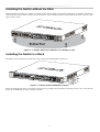
Installing the Switch without the Rack............................................................................................................................................................9
Installing the Switch in a Rack........................................................................................................................................................................9
Mounting the Switch in a Standard 19" Rack................................................................................................................................................10
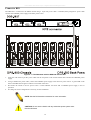
RPS Installation.............................................................................................................................................................................................11
Connecting the Switch ...................................................................................................................................13
Switch to End Node ......................................................................................................................................................................................13
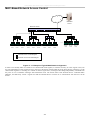
Switch to Hub or Switch ...............................................................................................................................................................................14
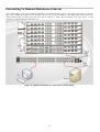
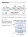
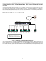
Connecting To Network Backbone or Server................................................................................................................................................15
Introduction to Switch Management ...........................................................................................................16
Management Options ................................................................................................................................................................... 16
Web-based Management Interface ................................................................................................................................................................16
SNMP-Based Management ...........................................................................................................................................................................16
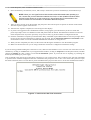
Connecting the Console Port (RS-232 DCE) ................................................................................................................................................16
First Time Connecting to the Switch.............................................................................................................................................................18
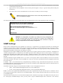
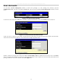
Password Protection ......................................................................................................................................................................................18
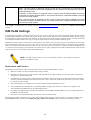
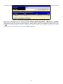
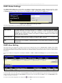
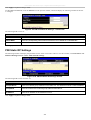
SNMP Settings..............................................................................................................................................................................................19
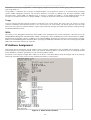
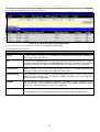
IP Address Assignment .................................................................................................................................................................................20
iii
xStack DGS-3600 Series Layer 3 Gigabit Ethernet Managed Switch
Web-based Switch Configuration.................................................................................................................22
Introduction.................................................................................................................................................................................. 22
Login to Web Manager .................................................................................................................................................................................22
Web-based User Interface .............................................................................................................................................................................23
Web Pages.....................................................................................................................................................................................................24
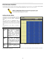
Administration ...............................................................................................................................................25
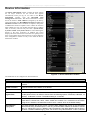
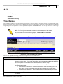
Device Information ...................................................................................................................................................................... 26
Stacking ....................................................................................................................................................................................... 29
Port Configuration........................................................................................................................................................................ 33
Port Settings ..................................................................................................................................................................................................33
Port Error Disabled ...................................................................................................................................................................... 35
Port Description ............................................................................................................................................................................................36
User Accounts.............................................................................................................................................................................. 37
Port Mirroring .............................................................................................................................................................................. 38
System Log Settings..................................................................................................................................................................... 39
System Log Save Mode Settings...................................................................................................................................................................40
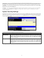
System Severity Settings.............................................................................................................................................................. 41
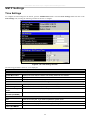
SNTP Settings.............................................................................................................................................................................. 42
Time Settings ................................................................................................................................................................................................42
Time Zone and DST......................................................................................................................................................................................43
MAC Notification Settings .......................................................................................................................................................... 45
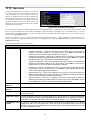
TFTP Services.............................................................................................................................................................................. 46
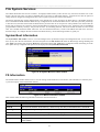
File System Services .................................................................................................................................................................... 47
System Boot Information ..............................................................................................................................................................................47
FS Information ..............................................................................................................................................................................................47
Directory .......................................................................................................................................................................................................48
Rename .........................................................................................................................................................................................................48
Copy..............................................................................................................................................................................................................49
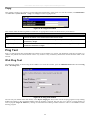
Ping Test ...................................................................................................................................................................................... 49
IPv4 Ping Test...............................................................................................................................................................................................49
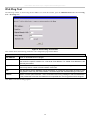
IPv6 Ping Test...............................................................................................................................................................................................50
IPv6 Neighbor.............................................................................................................................................................................. 51
IPv6 Neighbor Settings .................................................................................................................................................................................51
DHCP Auto Configuration Settings............................................................................................................................................. 52
SNMP Manager ........................................................................................................................................................................... 53
SNMP Settings..............................................................................................................................................................................................53
SNMP Traps Settings....................................................................................................................................................................................54
SNMP User Table .........................................................................................................................................................................................54
SNMP View Table ........................................................................................................................................................................................56
SNMP Group Table.......................................................................................................................................................................................57
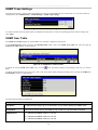
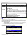
SNMP Community Table Configuration.......................................................................................................................................................58
SNMP Host Table .........................................................................................................................................................................................59
SNMP Engine ID ..........................................................................................................................................................................................60
iv
xStack DGS-3600 Series Layer 3 Gigabit Ethernet Managed Switch
IP-MAC-Port Binding.................................................................................................................................................................. 61
ACL Mode ....................................................................................................................................................................................................61
IP-MAC Binding Port ...................................................................................................................................................................................63
IP-MAC Binding Table.................................................................................................................................................................................64
IP-MAC Binding Blocked.............................................................................................................................................................................65
sFlow............................................................................................................................................................................................ 66
sFlow Global Settings ...................................................................................................................................................................................66
sFlow Analyzer Settings................................................................................................................................................................................67
sFlow Sampler Settings.................................................................................................................................................................................69
sFlow Counter Poller Settings.......................................................................................................................................................................71
D-Link Single IP Management .................................................................................................................................................... 73
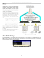
Single IP Management (SIM) Overview .......................................................................................................................................................73
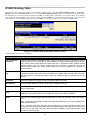
SIM Using the Web Interface........................................................................................................................................................................74
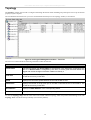
Topology .......................................................................................................................................................................................................76
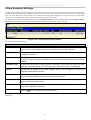
Tool Tips.......................................................................................................................................................................................................78
Right-Click....................................................................................................................................................................................................79
Menu Bar ......................................................................................................................................................................................................81
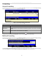
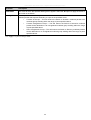
Firmware Upgrade ........................................................................................................................................................................................82
Configuration File Backup/Restore...............................................................................................................................................................82
Upload Log File ............................................................................................................................................................................................83
Layer 2 Features ............................................................................................................................................84
VLANs......................................................................................................................................................................................... 84
Understanding IEEE 802.1p Priority.............................................................................................................................................................84
VLAN Description ........................................................................................................................................................................................84
IEEE 802.1Q VLANs....................................................................................................................................................................................85
Static VLAN Entry........................................................................................................................................................................................89
GVRP Setting................................................................................................................................................................................................91
Double VLANs .............................................................................................................................................................................................92
Protocol VLANs ...........................................................................................................................................................................................96
Protocol Group VLAN Settings ....................................................................................................................................................................97
Protocol VLAN Port Settings........................................................................................................................................................................98
Trunking....................................................................................................................................................................................... 99
Link Aggregation ........................................................................................................................................................................................100
LACP Port Settings .....................................................................................................................................................................................102
IGMP Snooping ......................................................................................................................................................................... 103
IGMP Snooping ..........................................................................................................................................................................................103
Router Port Settings ....................................................................................................................................................................................105
ISM VLAN Settings................................................................................................................................................................... 106
Limited IP Multicast Range ....................................................................................................................................................... 110
MLD Snooping .......................................................................................................................................................................... 111
MLD Control Messages ..............................................................................................................................................................................111
MLD Snooping Settings..............................................................................................................................................................................111
MLD Router Port Settings...........................................................................................................................................................................113
Spanning Tree ............................................................................................................................................................................ 115
v
xStack DGS-3600 Series Layer 3 Gigabit Ethernet Managed Switch
STP Bridge Global Settings ........................................................................................................................................................................118
MST Configuration Identification...............................................................................................................................................................120
MSTP Port Information...............................................................................................................................................................................122
STP Instance Settings..................................................................................................................................................................................123
STP Port Settings ........................................................................................................................................................................................124
Forwarding................................................................................................................................................................................. 126
Unicast Forwarding.....................................................................................................................................................................................126
Multicast Forwarding ..................................................................................................................................................................................126
Multicast Filtering Mode.............................................................................................................................................................................127
Layer 3 Features ..........................................................................................................................................129
IPv6............................................................................................................................................................................................ 130
Overview.....................................................................................................................................................................................................130
Packet Format .............................................................................................................................................................................................131
Address Format ...........................................................................................................................................................................................132
ICMPv6.......................................................................................................................................................................................................134
Neighbor Discovery ....................................................................................................................................................................................134
IP Multinetting ........................................................................................................................................................................... 135
Interface Settings ....................................................................................................................................................................... 136
MD5 Key Settings...................................................................................................................................................................... 140
Route Redistribution Settings .................................................................................................................................................... 141
Routing Table............................................................................................................................................................................. 142
IPv4 Static/Default Route Settings..............................................................................................................................................................142
IPv6 Static/Default Route Settings..............................................................................................................................................................143
Route Preference Settings .......................................................................................................................................................... 145
Static ARP Settings.................................................................................................................................................................... 147
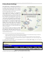
Policy Route Settings ................................................................................................................................................................. 148
RIP ............................................................................................................................................................................................. 150
RIP Global Settings.....................................................................................................................................................................................151
RIP Interface Settings .................................................................................................................................................................................152
OSPF.......................................................................................................................................................................................... 153
Including the NSSA ....................................................................................................................................................................................168
OSPF Global Settings .................................................................................................................................................................................170
OSPF Area Setting ......................................................................................................................................................................................170
OSPF Interface Settings ..............................................................................................................................................................................172
OSPF Virtual Link Settings.........................................................................................................................................................................174
OSPF Area Aggregation Settings................................................................................................................................................................175
OSPF Host Route Settings ..........................................................................................................................................................................176
DHCP/BOOTP Relay ................................................................................................................................................................ 178
DHCP / BOOTP Relay Global Settings ......................................................................................................................................................178
DHCP/BOOTP Relay Interface Settings.....................................................................................................................................................180
DHCP Server ............................................................................................................................................................................. 181
DHCP Server Global Settings .....................................................................................................................................................................181
DHCP Server Exclude Address Settings .....................................................................................................................................................182
Create DHCP Pool ......................................................................................................................................................................................182
vi
xStack DGS-3600 Series Layer 3 Gigabit Ethernet Managed Switch
DHCP Server Dynamic Binding .................................................................................................................................................................185
DHCP Server Manual Binding....................................................................................................................................................................185
DNS Relay ................................................................................................................................................................................. 187
DNS Relay Global Settings.........................................................................................................................................................................187
DNS Relay Static Settings...........................................................................................................................................................................188
VRRP ......................................................................................................................................................................................... 189
VRRP Global Settings.................................................................................................................................................................................189
VRRP Virtual Router Settings ....................................................................................................................................................................189
VRRP Authentication Settings....................................................................................................................................................................193
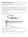
IP Multicast Routing Protocol.................................................................................................................................................... 194
IGMP Interface Settings..............................................................................................................................................................................196
DVMRP Interface Configuration............................................................................................................................................... 198
DVMRP Global Settings.............................................................................................................................................................................198
DVMRP Interface Settings..........................................................................................................................................................................198
PIM Protocol.............................................................................................................................................................................. 200
PIM Global Settings....................................................................................................................................................................................201
PIM Parameter Settings...............................................................................................................................................................................201
PIM Interface Settings.................................................................................................................................................................................202
PIM Candidate BSR Settings ......................................................................................................................................................................203
PIM Candidate RP Settings.........................................................................................................................................................................204
PIM Static RP Settings................................................................................................................................................................................205
PIM Register Checksum Settings................................................................................................................................................................206
QoS ................................................................................................................................................................207
Advantages of QoS .....................................................................................................................................................................................207
Understanding QoS .....................................................................................................................................................................................208
Port Bandwidth .......................................................................................................................................................................... 209
QoS Scheduling Mechanism ...................................................................................................................................................... 209
QoS Output Scheduling ............................................................................................................................................................. 210
Configuring the Combination Queue ..........................................................................................................................................................210
802.1p Default Priority .............................................................................................................................................................. 212
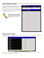
802.1p User Priority................................................................................................................................................................... 212
ACL ...............................................................................................................................................................213
Time Range................................................................................................................................................................................ 213
Access Profile Table .................................................................................................................................................................. 214
ACL Flow Meter........................................................................................................................................................................ 230
CPU Interface Filtering.............................................................................................................................................................. 233
CPU Interface Filtering State Settings ........................................................................................................................................................233
CPU Interface Filtering Profile Table .........................................................................................................................................................233
Security .........................................................................................................................................................246
Traffic Control ........................................................................................................................................................................... 246
Port Security............................................................................................................................................................................... 249
Port Security Entries .................................................................................................................................................................. 250
Port Access Entity (802.1X) ...................................................................................................................................................... 251
vii
xStack DGS-3600 Series Layer 3 Gigabit Ethernet Managed Switch
802.1X Port-Based and MAC-Based Access Control .................................................................................................................................251
Understanding 802.1X Port-based and MAC-based Network Access Control ...........................................................................................254
Port-Based Network Access Control...........................................................................................................................................................254
MAC-Based Network Access Control ........................................................................................................................................................255
Guest VLANs..............................................................................................................................................................................................256
Guest VLAN ...............................................................................................................................................................................................257
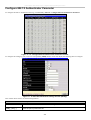
Configure 802.1X Authenticator Parameter................................................................................................................................................258
802.1X User ................................................................................................................................................................................................260
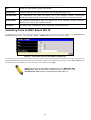
Initializing Ports for Port Based 802.1X .....................................................................................................................................................260
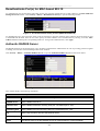
Initializing Ports for MAC Based 802.1X ...................................................................................................................................................261
Reauthenticate Port(s) for Port Based 802.1X.............................................................................................................................................262
Reauthenticate Port(s) for MAC-based 802.1X...........................................................................................................................................263
Authentic RADIUS Server..........................................................................................................................................................................263
Web Authentication Configuration ............................................................................................................................................ 264
Conditions and Limitations .........................................................................................................................................................................264
Trust Host................................................................................................................................................................................... 268
Access Authentication Control .................................................................................................................................................. 269
Authentication Policy and Parameter Settings ............................................................................................................................................270
Application Authentication Settings............................................................................................................................................................270
Authentication Server Group ......................................................................................................................................................................271
Authentication Server Host .........................................................................................................................................................................272
Login Method Lists .....................................................................................................................................................................................274
Enable Method Lists ...................................................................................................................................................................................275
Configure Local Enable Password ..............................................................................................................................................................277
Enable Admin .............................................................................................................................................................................................277
Safeguard Engine ....................................................................................................................................................................... 278
Safeguard Engine Settings ......................................................................................................................................................... 279
Traffic Segmentation.................................................................................................................................................................. 280
Secure Socket Layer (SSL) ........................................................................................................................................................ 281
Download Certificate ..................................................................................................................................................................................281
Ciphersuite ..................................................................................................................................................................................................281
SSH ............................................................................................................................................................................................ 284
SSH Server Configuration...........................................................................................................................................................................284
SSH Authentication Mode and Algorithm Settings.....................................................................................................................................285
SSH User Authentication ............................................................................................................................................................................287
Monitoring ....................................................................................................................................................288
Device Status ............................................................................................................................................................................. 288
Stacking Information.................................................................................................................................................................. 289
Module Information ................................................................................................................................................................... 290
CPU Utilization.......................................................................................................................................................................... 291
Port Utilization........................................................................................................................................................................... 292
Packets ....................................................................................................................................................................................... 293
Received (RX).............................................................................................................................................................................................293
UMB Cast (RX) ..........................................................................................................................................................................................295
viii
xStack DGS-3600 Series Layer 3 Gigabit Ethernet Managed Switch
Transmitted (TX) ........................................................................................................................................................................................297
Errors ......................................................................................................................................................................................... 299
Received (RX).............................................................................................................................................................................................299
Transmitted (TX) ........................................................................................................................................................................................301
Packet Size ................................................................................................................................................................................. 303
Browse Router Port.................................................................................................................................................................... 305
Browse MLD Router Port .......................................................................................................................................................... 305
VLAN Status.............................................................................................................................................................................. 305
Port Access Control ................................................................................................................................................................... 306
Authenticator State......................................................................................................................................................................................306
Authenticator Statistics ...............................................................................................................................................................................308
Authenticator Session Statistics ..................................................................................................................................................................309
Authenticator Diagnostics ...........................................................................................................................................................................310
RADIUS Authentication .............................................................................................................................................................................312
RADIUS Accounting ..................................................................................................................................................................................313
MAC Address Table .................................................................................................................................................................. 315
IGMP Snooping Group .............................................................................................................................................................. 316
MLD Snooping Group ................................................................................................................................................................................317
Trace Route................................................................................................................................................................................ 318
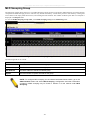
IGMP Snooping Forwarding...................................................................................................................................................... 319
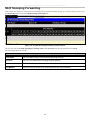
MLD Snooping Forwarding....................................................................................................................................................... 320
IP Forwarding Table .................................................................................................................................................................. 321
Browse Routing Table ............................................................................................................................................................... 322
Browse IP Multicast Forwarding Table ..................................................................................................................................... 322
Browse IP Multicast Interface Table.......................................................................................................................................... 322
Browse IGMP Group Table ....................................................................................................................................................... 323
DVMRP Monitoring .................................................................................................................................................................. 323
Browse DVMRP Routing Table..................................................................................................................................................................323
Browse DVMRP Neighbor Table ...............................................................................................................................................................323
Browse DVMRP Routing Next Hop Table .................................................................................................................................................323
PIM Monitoring ......................................................................................................................................................................... 324
Browse PIM Neighbor Table ......................................................................................................................................................................324
Browse PIM IP Multicast Route Table .......................................................................................................................................................324
Browse PIM RP Set Table ..........................................................................................................................................................................324
OSPF Monitoring....................................................................................................................................................................... 325
Browse OSPF LSDB Table.........................................................................................................................................................................325
Browse OSPF Neighbor Table ....................................................................................................................................................................326
Browse OSPF Virtual Neighbor Table........................................................................................................................................................326
Switch Logs ............................................................................................................................................................................... 327
Browse ARP Table......................................................................................................................................................................................328
Session Table ..............................................................................................................................................................................................328
Switch Maintenance.....................................................................................................................................329
Reset........................................................................................................................................................................................... 329
ix
xStack DGS-3600 Series Layer 3 Gigabit Ethernet Managed Switch
Reboot System ........................................................................................................................................................................... 329
Save Services ............................................................................................................................................................................. 330
Save Changes ..............................................................................................................................................................................................330
Current Configuration Settings ...................................................................................................................................................................331
Logout........................................................................................................................................................................................ 331
Technical Specifications ..............................................................................................................................332
Cables and Connectors ................................................................................................................................334
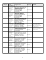
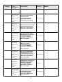
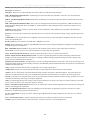
System Log Entries ......................................................................................................................................335
Cable Lengths...............................................................................................................................................347
Glossary ........................................................................................................................................................348
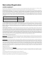
Warranties/Registration..............................................................................................................................351
Tech Support ...............................................................................................................................................................................................358
x
xStack DGS-3600 Series Layer 3 Gigabit Ethernet Managed Switch
Preface
The xStack DGS-3600 Series User Manual is divided into sections that describe the system installation and operating instructions
with examples.
Section 1, Introduction - Describes the Switch and its features.
Section 2, Installation - Helps you get started with the basic installation of the Switch and also describes the front panel, rear
panel, side panels, and LED indicators of the Switch.
Section 3, Connecting the Switch - Tells how you can connect the Switch to your Ethernet/Fast Ethernet network.
Section 4, Introduction to Switch Management - Introduces basic Switch management features, including password protection,
SNMP settings, IP address assignment and connecting devices to the Switch.
Section 5, Introduction to Web-based Switch Management - Talks about connecting to and using the Web-based switch
management feature on the Switch.
Section 6, Administration - A detailed discussion about configuring the basic functions of the Switch, including Device
Information, Stacking, Port Configuration, User Accounts, Port Mirroring, System Log, System Severity Settings, SNTP Settings,
MAC Notification Settings, TFTP Services, File System Services, Ping Test, IPv6 Neighbor, DHCP Auto Configuration, SNMP
Manager, IP-MAC-Port Binding, sFlow, and Single IP Management Settings.
Section 7, Layer 2 Features - A discussion of Layer 2 features of the Switch, including VLAN, Trunking, IGMP Snooping,
MLD Snooping, Spanning Tree, and Forwarding & Filtering.
Section 8, Layer 3 Features - A discussion of Layer 3 features of the Switch, including Interface Settings, MD5 Key Settings,
Route Redistribution Settings, Static/Default Route Settings, Route Preference Settings, Static ARP Settings, Policy Route
Settings, RIP, OSPF, DCHP/BOOTP Relay, DNS Relay, VRRP, and IP Multicast Routing Protocol.
Section 9, QoS - Features information on QoS, including Bandwidth Control, QoS Scheduling Mechanism, QoS Output
Scheduling, 802.1p Default Priority, and 802.1p User Priority.
Section 10, ACL - Discussion on the ACL function of the Switch, including Time Range, Access Profile Table, ACL Flow Meter,
and CPU Interface Filtering.
Section 11, Security – A discussion on the Security functions on the Switch, including Traffic Control, Port Security, 802.1X,
Trust Host, Web Authentication, Trust Host, Access Authentication Control, Safeguard Engine, Traffic Segmentation, SSL, and
SSH.
Section 12, Monitoring – Features information on Monitoring including Device Status, Module Information, CPU Utilization,
Port Utilization, Packets, Errors, Packet Size, Browse Router Port, Browse MLD Router Port, VLAN Status, Port Access Control,
MAC Address Table, IGMP Snooping Group, MLD Snooping Group, Trace Route, IGMP Snooping Forwarding, MLD Snooping
Forwarding, IP Forwarding Table, Browse Routing Table, Browse IP Multicast Forwarding Table, Browse IP Multicast Interface
Table, Browse IGMP Group Table, DVMRP Monitor, PIM Monitor, OSPF Monitor, Switch Logs, Browse ARP Table and
Session Table.
Appendix A, Technical Specifications - Technical specifications for the DSG-3612, DGS-3627, DGS-3627G and the DGS-3650.
Appendix B, Cables and Connectors - Describes the RJ-45 receptacle/connector, straight through and crossover cables and
standard pin assignments.
Appendix C, Cable Lengths - Information on cable types and maximum distances.
Glossary - Lists definitions for terms and acronyms used in this document.
xi
xStack DGS-3600 Series Layer 3 Gigabit Ethernet Managed Switch
Intended Readers
The xStack DGS-3600 Series User Manual contains information for setup and management of the Switch. The term, “the Switch”
will be used when referring to all three switches. This manual is intended for network managers familiar with network
management concepts and terminology.
Typographical Conventions
Convention
Description
[]
In a command line, square brackets indicate an optional entry. For example: [copy filename]
means that optionally you can type copy followed by the name of the file. Do not type the
brackets.
Bold font
Indicates a button, a toolbar icon, menu, or menu item. For example: Open the File menu
and choose Cancel. Used for emphasis. May also indicate system messages or prompts
appearing on your screen. For example: You have mail. Bold font is also used to represent
filenames, program names and commands. For example: use the copy command.
Boldface
Typewriter Font
Indicates commands and responses to prompts that must be typed exactly as printed in the
manual.
Initial capital letter
Indicates a window name. Names of keys on the keyboard have initial capitals. For example:
Click Enter.
Italics
Indicates a window name or a field. Also can indicate a variables or parameter that is
replaced with an appropriate word or string. For example: type filename means that you
should type the actual filename instead of the word shown in italic.
Menu Name > Menu
Option
Menu Name > Menu Option Indicates the menu structure. Device > Port > Port
Properties means the Port Properties menu option under the Port menu option that is
located under the Device menu.
Notes, Notices, and Cautions
A NOTE indicates important information that helps you make better use of your device.
A NOTICE indicates either potential damage to hardware or loss of data and tells you
how to avoid the problem.
A CAUTION indicates a potential for property damage, personal injury, or death.
xii
xStack DGS-3600 Series Layer 3 Gigabit Ethernet Managed Switch
Safety Instructions
Use the following safety guidelines to ensure your own personal safety and to help protect your system from potential damage.
Throughout this document, the caution icon (
) is used to indicate cautions and precautions that you need to review and follow.
Safety Cautions
To reduce the risk of bodily injury, electrical shock, fire, and damage to the equipment, observe the following precautions.
•
Observe and follow service markings.
•
Do not service any product except as explained in your system documentation.
•
Opening or removing covers that are marked with the triangular symbol with a lightning bolt may expose you to
electrical shock.
•
•
Only a trained service technician should service components inside these compartments.
If any of the following conditions occur, unplug the product from the electrical outlet and replace the part or contact your
trained service provider:
•
The power cable, extension cable, or plug is damaged.
•
An object has fallen into the product.
•
The product has been exposed to water.
•
The product has been dropped or damaged.
•
The product does not operate correctly when you follow the operating instructions.
•
Keep your system away from radiators and heat sources. Also, do not block cooling vents.
•
Do not spill food or liquids on your system components, and never operate the product in a wet environment. If the system
gets wet, see the appropriate section in your troubleshooting guide or contact your trained service provider.
•
Do not push any objects into the openings of your system. Doing so can cause fire or electric shock by shorting out interior
components.
•
Use the product only with approved equipment.
•
Allow the product to cool before removing covers or touching internal components.
•
Operate the product only from the type of external power source indicated on the electrical ratings label. If you are not sure
of the type of power source required, consult your service provider or local power company.
•
To help avoid damaging your system, be sure the voltage on the power supply is set to match the power available at your
location:
•
115 volts (V)/60 hertz (Hz) in most of North and South America and some Far Eastern countries such as South
Korea and Taiwan
•
100 V/50 Hz in eastern Japan and 100 V/60 Hz in western Japan
•
230 V/50 Hz in most of Europe, the Middle East, and the Far East
•
Also, be sure that attached devices are electrically rated to operate with the power available in your location.
•
Use only approved power cable(s). If you have not been provided with a power cable for your system or for any ACpowered option intended for your system, purchase a power cable that is approved for use in your country. The power cable
must be rated for the product and for the voltage and current marked on the product's electrical ratings label. The voltage and
current rating of the cable should be greater than the ratings marked on the product.
•
To help prevent electric shock, plug the system and peripheral power cables into properly grounded electrical outlets. These
cables are equipped with three-prong plugs to help ensure proper grounding. Do not use adapter plugs or remove the
grounding prong from a cable. If you must use an extension cable, use a 3-wire cable with properly grounded plugs.
•
Observe extension cable and power strip ratings. Make sure that the total ampere rating of all products plugged into the
extension cable or power strip does not exceed 80 percent of the ampere ratings limit for the extension cable or power strip.
xiii
xStack DGS-3600 Series Layer 3 Gigabit Ethernet Managed Switch
•
To help protect your system from sudden, transient increases and decreases in electrical power, use a surge suppressor, line
conditioner, or uninterruptible power supply (UPS).
•
Position system cables and power cables carefully; route cables so that they cannot be stepped on or tripped over. Be sure
that nothing rests on any cables.
•
Do not modify power cables or plugs. Consult a licensed electrician or your power company for site modifications. Always
follow your local/national wiring rules.
•
When connecting or disconnecting power to hot-pluggable power supplies, if offered with your system, observe the
following guidelines:
•
•
Install the power supply before connecting the power cable to the power supply.
•
Unplug the power cable before removing the power supply.
•
If the system has multiple sources of power, disconnect power from the system by unplugging all power cables from
the power supplies.
Move products with care; ensure that all casters and/or stabilizers are firmly connected to the system. Avoid sudden stops
and uneven surfaces.
General Precautions for Rack-Mountable Products
Observe the following precautions for rack stability and safety. Also, refer to the rack installation documentation accompanying
the system and the rack for specific caution statements and procedures.
•
Systems are considered to be components in a rack. Thus, "component" refers to any system as well as to various peripherals
or supporting hardware.
•
Before working on the rack, make sure that the stabilizers are secured to the rack, extended to the floor, and that the full
weight of the rack rests on the floor. Install front and side stabilizers on a single rack or front stabilizers for joined multiple
racks before working on the rack.
•
Always load the rack from the bottom up, and load the heaviest item in the rack first.
•
Make sure that the rack is level and stable before extending a component from the rack.
•
Use caution when pressing the component rail release latches and sliding a component into or out of a rack; the slide rails
can pinch your fingers.
•
After a component is inserted into the rack, carefully extend the rail into a locking position, and then slide the component
into the rack.
•
Do not overload the AC supply branch circuit that provides power to the rack. The total rack load should not exceed 80
percent of the branch circuit rating.
•
Ensure that proper airflow is provided to components in the rack.
•
Do not step on or stand on any component when servicing other components in a rack.
NOTE: A qualified electrician must perform all connections to DC power and to safety
grounds. All electrical wiring must comply with applicable local, regional or national codes
and practices.
CAUTION: Never defeat the ground conductor or operate the equipment in the absence of a
suitably installed ground conductor. Contact the appropriate electrical inspection authority or
an electrician if you are uncertain that suitable grounding is available.
xiv
xStack DGS-3600 Series Layer 3 Gigabit Ethernet Managed Switch
CAUTION: The system chassis must be positively grounded to the rack cabinet frame. Do
not attempt to connect power to the system until grounding cables are connected. A
qualified electrical inspector must inspect completed power and safety ground wiring. An
energy hazard will exist if the safety ground cable is omitted or disconnected.
CAUTION: Do not replace the battery with an incorrect type. The risk of explosion exists if
the replacement battery is not the correct lithium battery type. Dispose of used batteries
according to the instructions.
Protecting Against Electrostatic Discharge
Static electricity can harm delicate components inside your system. To prevent static damage, discharge static electricity from
your body before you touch any of the electronic components, such as the microprocessor. You can do so by periodically touching
an unpainted metal surface on the chassis.
You can also take the following steps to prevent damage from electrostatic discharge (ESD):
1.
When unpacking a static-sensitive component from its shipping carton, do not remove the component from the antistatic
packing material until you are ready to install the component in your system. Just before unwrapping the antistatic
packaging, be sure to discharge static electricity from your body.
2.
When transporting a sensitive component, first place it in an antistatic container or packaging.
3.
Handle all sensitive components in a static-safe area. If possible, use antistatic floor pads, workbench pads and an
antistatic grounding strap.
xv
xStack DGS-3600 Series Layer 3 Stackable Fast Ethernet Managed Switch
Section 1
Introduction
xStack DGS-3600 Series
Gigabit Ethernet Technology
Switch Description
Features
Ports
Front-Panel Components
Side Panel Description
Rear Panel Description
xStack DGS-3600 Series
The DGS-3600 switch series is a member of the D-Link xStack switch family. xStack is a complete family of stackable devices
that ranges from edge 10/100Mbps switches to core Gigabit switches. xStack provides unsurpassed performance, fault tolerance,
scalable flexibility, robust security, standard-based interoperability and an impressive support for 10 Gigabit technology to futureproof departmental and enterprise network deployments with an easy migration path.
The following manual describes the installation, maintenance and configurations concerning members of the D-Link DGS-3600
switch series, including the DGS-3612G, DGS-3627, DGS-3627G, and the DGS-3650. These four switches are identical in
configurations and very similar in basic hardware and consequentially, most of the information in this manual will be universal to
the total group of Switches. Corresponding screen pictures of the web manager may be taken from any one of these switches but
the configuration will be identical, except for varying port counts. For the remainder of this document, we will refer to the DGS3600 as the switch in question for examples, configurations and explanations.
Gigabit Ethernet Technology
Gigabit Ethernet is an extension of IEEE 802.3 Ethernet utilizing the same packet structure, format, and support for CSMA/CD
protocol, full duplex, flow control, and management objects, but with a tenfold increase in theoretical throughput over 100Mbps
Fast Ethernet and a one hundred-fold increase over 10Mbps Ethernet. Since it is compatible with all 10Mbps and 100Mbps Ethernet environments, Gigabit Ethernet provides a straightforward upgrade without wasting a company's existing investment in
hardware, software, and trained personnel.
The increased speed and extra bandwidth offered by Gigabit Ethernet are essential to coping with the network bottlenecks that
frequently develop as computers and their busses get faster and more users using applications that generate more traffic.
Upgrading key components, such as your backbone and servers to Gigabit Ethernet can greatly improve network response times
as well as significantly speed up the traffic between your sub networks.
Gigabit Ethernet enables fast optical fiber connections to support video conferencing, complex imaging, and similar data-intensive
applications. Likewise, since data transfers occur 10 times faster than Fast Ethernet, servers outfitted with Gigabit Ethernet NIC's
are able to perform 10 times the number of operations in the same amount of time.
In addition, the phenomenal bandwidth delivered by Gigabit Ethernet is the most cost-effective method to take advantage of today
and tomorrow's rapidly improving switching and routing internetworking technologies.
Switch Description
The Switch is equipped with unshielded twisted-pair (UTP) cable ports providing dedicated 10, 100 or 1000 Mbps bandwidth. The
DGS-3627 is equipped with twenty-four 10/100/1000BASE-T ports, and the DGS-3650 has forty-eight 10/100/1000BASE-T
ports, all of which are Auto MDI-X/MDI-II convertible ports that can be used for uplinking to another switch. The DGS-3612GG
is equipped with twelve 100/1000Mbps SFP (Small Form Factor Portable) ports, in addition to four 1000BASE-T located on the
front panel. These ports can be used for connecting PCs, printers, servers, hubs, routers, switches and other networking devices.
The dual speed ports use standard twisted-pair cabling and are ideal for segmenting networks into small, connected sub networks
for superior performance. Each 10/100/1000 port can support up to 2000 Mbps of throughput in full-duplex mode. In addition, the
Switch has four 1000Mbps SFP combo ports located on the front panel. These gigabit combo ports are ideal for connecting to a
server or network backbone.
1
xStack DGS-3600 Series Layer 3 Stackable Fast Ethernet Managed Switch
The DGS-3627G contains twenty-four 1000Mbps SFP (Small Form Factor Portable) ports, in addition to four 1000BASE-T
located on the front panel. The SFP combo ports are to be used with fiber-optical transceiver cabling in order to uplink various
other networking devices for a gigabit link that may span great distances. The SFP ports can also support full-duplex
transmissions, have auto-negotiation and can be used with DEM-310GT (1000BASE-LX), DEM-311GT (1000BASE-SX), DEM312GT2 (1000BASE-SX), DEM-314GT (1000BASE-LH), DEM-315GT (1000BASE-ZX), DEM-330T/R (WDM Transceiver)
and the DEM-331T/R (WDM Transceiver) transceivers. These ports are referred to as “combo” ports which means that both the
SFP ports and the 1000BASE-T ports are numbered the same and cannot be used simultaneously. Attempting to use the ports
simultaneously will cause a link down status for the 1000BASE-T ports. SFP ports will always have priority over these
1000BASE-T ports.
Each switch also contains open slots in the rear of the Switch, which are used to add optional single-port 10GE modules. Two
available slots reside within the DGS-3650, while the DGS-3627 and DGS-3627G both contain three slots. These modules, the
DEM-410CX CX4 and the DEM-410X XFP, are IEEE 802.3ae and IEEE 802.3ak compliant and support full-duplex mode only.
More information will be provided on these modules later in this manual.
This Switch enables the network to use some of the most demanding multimedia and imaging applications concurrently with other
user applications without creating bottlenecks. The built-in console interface can be used to configure the Switch's settings for
priority queuing, VLANs, and port trunk groups, port monitoring, and port speed.
Features
•
•
•
•
•
•
•
•
•
•
•
•
•
•
•
•
•
•
•
•
•
•
•
•
•
•
•
•
•
•
•
•
•
•
IEEE 802.3ad Link Aggregation Control Protocol support.
IEEE 802.1X Port-based and MAC-based Access Control
IEEE 802.1Q VLAN
IEEE 802.1D Spanning Tree, IEEE 802.1W Rapid Spanning Tree and IEEE 802.1s Multiple Spanning Tree support
Access Control List (ACL) support
Single IP Management support
Access Authentication Control utilizing TACACS, XTACACS and TACACS+
Internal Flash Drive for saving configurations and firmware
Simple Network Time Protocol support
MAC Notification support
System and Port Utilization support
System Log Support
Support port-based enable and disable
Address table: Supports up to 16K MAC addresses per device
Supports a packet buffer of up to 2M bytes
Port Trunking with flexible load distribution and fail-over function
IGMP Snooping support
MLD Snooping support
SNMP support
Secure Sockets Layer (SSL) and Secure Shell (SSH) support
Port Mirroring support
Web-based Access Control
MIB support for:
RFC1213 MIB II
RFC1493 Bridge
RFC2819 RMON
RFC2665 Ether-like MIB
RFC2863 Interface MIB
Private MIB
RFC2674 for 802.1p
IEEE 802.1X MIB
IEEE 802.3x flow control in full duplex mode
IEEE 802.1p Priority Queues
IEEE 802.3u 100BASE-TX compliant
2
xStack DGS-3600 Series Layer 3 Stackable Fast Ethernet Managed Switch
•
•
•
•
•
•
•
•
•
RS-232 DCE console port for Switch management
Provides parallel LED display for port status such as link/act, speed, etc.
IEEE 802.3 10BASE-T compliant
High performance switching engine performs forwarding and filtering at wire speed, maximum 14, 881 packets/sec
on each 10Mbps Ethernet port, maximum 148,810 packet/sec on 100Mbps Fast Ethernet port and 1,488,100 for each
Gigabit port.
Full and half-duplex for both 10Mbps and 100Mbps connections. Full duplex allows the switch port to
simultaneously transmit and receive data. It only works with connections to full-duplex-capable end stations and
switches. Connections to a hub must take place at half-duplex
Support broadcast storm filtering
Non-blocking store and forward switching scheme capability to support rate adaptation and protocol conversion
Supports by-port Egress/Ingress rate control.
Efficient self-learning and address recognition mechanism enables forwarding rate at wire speed
Ports
The following table lists the relative ports that are present within each switch:
DGS-3627
DGS-3627G
DGS-3650
DGS-3612G
Twenty-four
10/100/100BASE-T
Twenty-four 1000Mbps SFP
Ports
Forty-eight
10/100/100BASE-T
Twelve 100/1000Mbps
SFP Ports
Four SFP Combo Ports
Four 1000BASE-T Combo
Ports
Four SFP Combo Ports
Four 1000BASE-T
Combo Ports
Three open slots used to
add single-port 10GE
modules
Three open slots used to add
single-port 10GE modules
Two open slots used to
add single-port 10GE
modules
One female DCE RS-232
DB-9 console port
One female DCE RS-232 DB-9
console port
One female DCE RS-232
DB-9 console port
One female DCE RS-232
DB-9 console port
The following table lists the features and compatibility for each type of port present in the xStack DGS-3600 series.
10/100/1000BASE-T
IEEE 802.3 compliant
IEEE 802.3u compliant
IEEE 802.3x flow control
support in full-duplex
One connector in the
rear to add an external
Redundant Power
Supply (DPS-500)
Auto MDI-X/MDI-II cross
over support
SFP Combo
1000BASE-T Combo
Supports the following SFP
transceivers:
DEM-310GT (1000BASE-LX)
DEM-311GT (1000BASE-SX)
DEM-312GT2 (1000BASE-LX)
DEM-314GT (1000BASE-LH)
DEM-315GT (1000BASE-ZX)
DEM-330T/R (WDM)
DEM-331T/R (WDM)
IEEE 802.3 compliant
IEEE 802.3ae compliant
IEEE 802.3u compliant
IEEE 802.3ak compliant
IEEE 802.3ab compliant
Full-duplex only
IEEE 802.3z compliant
Supports the following
modules:
IEEE 802.3x flow control
support in full-duplex
One connector in the
rear to add an external
Redundant Power
Supply (DPS-500)
Will take priority over its
10/100/1000BASE-T combo
ports
10GE Module
DEM-410CX Single-Port CX4
DEM-410X Single-Port XFP
One connector in the rear to
add an external Redundant
Power Supply (DPS-500)
IEEE 802.3z compliant
One connector in the rear to
add an external Redundant
Power Supply (DPS-500)
NOTE: The SFP combo ports on the Switch cannot be used simultaneously with the
corresponding 1000BASE-T ports. If both ports are in use at the same time (ex. port 25
of the SFP and port 25 of the 1000BASE-T), the SFP ports will take priority over the
combo ports and render the 1000BASE-T ports inoperable.
3
xStack DGS-3600 Series Layer 3 Gigabit Ethernet Managed Switch
Front-Panel Components
DGS-3612G
•
Twelve SFP 100/1000Mbps ports
•
Four Combo 1000BASE-T ports located to the right
•
One female DCE RS -232 DB-9 console port
•
LEDs for Power, Console, RPS, and Link/Act/Speed for each port
Figure 1- 1. Front Panel of the DGS-3612GG
DGS-3627
•
Twenty-four 10/100/1000BASE-T ports
•
Four Combo SFP ports located to the right
•
One female DCE RS-232 DB-9 console port
•
LEDs for Power, Console, RPS, Link/Act/Speed and 10GE for each port
•
Stacking Module Numbered LED
Figure 1- 2. Front Panel of the DGS-3627
DGS-3627G
•
Twenty-four SFP 1000Mbps ports
•
Four Combo 1000BASE-T ports located to the right
•
One female DCE RS -232 DB-9 console port
•
LEDs for Power, Console, RPS, Link/Act/Speed and 10GE for each port
•
Stacking Module Numbered LED
Figure 1- 3. Front Panel of the DGS-3627G
DGS-3650
•
Forty-eight 10/100/1000BASE-T ports
•
Four Combo SFP ports located to the right
•
One female DCE RS -232 DB-9 console port
•
LEDs for Power, Console, RPS, Link/Act/Speed and 10GE for each port
•
Stacking Module Numbered LED
Figure 1- 4. Front Panel of the DGS-3650
2
xStack DGS-3600 Series Layer 3 Gigabit Ethernet Managed Switch
LEDs
The following table lists the LEDs located on models of the xStack DGS-3600 switch along with their corresponding description:
LED Indicator
Color
Status
Description
Power
Green
Solid
Power On
Dark
Power Off
Solid
Console On
Dark
Console Off
Solid
RPS in use
Dark
RPS not in use or not present
Console
RPS
Green
Green
Stacking LED (To
be supported in
Release II)
Green
Numbered 1-12
Box ID of the Switch in the switch stack. This field will
read 1 for a switch in standalone mode. When the switch
in question is a master of a switch stack, the number of
the switch in the stack will be displayed, and the letter H
will flash alternatively with this number.
Port LEDs
(10/100/1000Mbps
ports)
Green
Solid
Denotes an active connection at 1000Mbps.
Blinking
Denotes data transfer at 1000Mbps.
Solid
Denotes an active connection at 10/100Mbps.
Blinking
Denotes data transfer at 10/100Mbps.
Dark
No Light
Link Down
Green
Solid
Denotes an active connection at 1000Mbps.
Blinking
Denotes data transfer at 1000Mbps.
Dark
No Light
Link Down
Green
Solid
Denotes an active connection.
Blinking
Denotes data transfer.
No Light
Link Down
SFP Port LED
10GE Module
LEDs (Located on
the front panel)
Orange
Dark
Figure 1- 5. DGS-3612G LEDs
Figure 1- 6. DGS-3627 LEDs
3
xStack DGS-3600 Series Layer 3 Gigabit Ethernet Managed Switch
Figure 1- 7. DGS-3627G LEDs
Figure 1- 8. DGS-3650 LEDs
Rear Panel Description
The rear panels of the DGS-3612G, DGS-3627, DGS-3627G and the DGS-3650 are described below.
DGS-3612G
The rear panel of the DGS-3612G contains an AC power connector, and an outlet for an optional external RPS.
Figure 1- 9. Rear panel view of the DGS-3612G
DGS-3627 and DGS-3627G
The rear panel of DGS-3627 and DGS-3627G contains an AC power connector, an outlet for an optional external RPS and three
slots for additional 10GE optional modules.
Figure 1- 10. Rear panel view of the DGS-3627(G)
DGS-3650
The rear panel of DGS-3650 contains an AC power connector, an outlet for an optional external RPS, a DCE RS-232 console port
and two slots for additional 10GE optional modules.
Figure 1- 11. Rear Panel view of DGS-3650
The rear panel includes an outlet for an optional external redundant power supply. When power fails, the optional external RPS
will take over all the power immediately and automatically. The AC power connector is a standard three-pronged connector that
supports the power cord. Plug-in the female connector of the provided power cord into this socket, and the male side of the cord
into a power outlet. The Switch automatically adjusts its power setting to any supply voltage in the range from 100 ~ 240 VAC at
50 ~ 60 Hz.
4
xStack DGS-3600 Series Layer 3 Gigabit Ethernet Managed Switch
Side Panel Description
The right-hand side panel of the Switch contains a system fan and ventilation along the entire right side. The left hand panel
includes a system fan and a heat vent. The system fans are used to dissipate heat. Do not block these openings on either side of the
Switch. Leave at least 6 inches of space at the rear and sides of the Switch for proper ventilation. Be reminded that without proper
heat dissipation and air circulation, system components might overheat, which could lead to system failure.
Figure 1- 12. Side Panels of the DGS-3627 and the DGS-3627G
Figure 1- 13. Side Panels of the DGS-3650
Figure 1- 14. Side Panels of the DGS-3612G
5
xStack DGS-3600 Series Layer 3 Gigabit Ethernet Managed Switch
10GE Uplink Modules
At the rear of the xStack DGS-3600 series switches reside optional module slots. This slot may be equipped with the DEM-410X
single-port 10GE XFP uplink module, or a DEM-410CX single-port 10GE CX4 uplink module, both sold separately.
Adding the DEM-410X optional module will allow the administrator to add a single-port 10GE stacking module which will
transmit information at a rate of ten gigabits a second. This port is compliant with standard IEEE 802.3ae, supports full-duplex
transmissions only and is to be used with XFP MSA compliant transceivers.
The DEM-410CX will too transfer information at a rate of ten gigabits a second but is used as an uplink module to a network
device. Compliant with the IEEE802.3ak standard, this module will use a 4-laned copper connector to transfer information in fullduplex mode, quickly and accurately. User beware, the cable and connector port used for this module is nearly identical to the
stacking ports and cables used for stacking in the xStack Series, but can in no way be interchangeable.
To install these modules, follow the simple steps listed below.
CAUTION: Before adding the optional module, make sure to disconnect all
power sources connected to the Switch. Failure to do so may result in an
electrical shock, which may cause damage, not only to the individual but to
the Switch as well.
At the back of the Switch to the left is the slot for the optional module, as shown in Figure 1-15 and Figure 1-16. This slot should
be covered with a faceplate that can be easily removed by loosening the screws and pulling off the plate.
Optional Module Slots
Figure 1- 15. Optional Module slots at the rear of the DGS-3627 (or DGS-3627G)
Optional Module Slots
Figure 1- 16. Optional Module slots at the rear of the DGS-3650
After removing the faceplate, remove the DEM-410X or DEM-410CX optional module from its box. The front panel should
resemble the drawings represented here.
Figure 1- 17. Front Panel of the DEM-410X and the DEM-410CX
Take the module and gently slide it in to the available slot at the rear of the Switch until it reaches the back, as shown in the
following figure. At the back of the slot are two sets of plugs that must be connected to the module. Gently, but firmly push in on
the module to secure it to the Switch. The module should fit snugly into the corresponding receptors.
6
xStack DGS-3600 Series Layer 3 Gigabit Ethernet Managed Switch
Figure 1- 18. Inserting the optional modules into the Switch.
Now tighten the two screws at adjacent ends of the module into the available screw holes on the Switch. The upgraded DGS3627/DGS-3627G/DGS-3650 is now ready for use.
Figure 1- 19. DGS-3627 with optional module installed.
Installing the SFP ports
The xStack DGS-3600 Series switches are equipped with SFP (Small Form Factor Portable) ports, which are to be used with
fiber-optical transceiver cabling in order to uplink various other networking devices for a gigabit link that may span great
distances. These SFP ports support full-duplex transmissions, have auto-negotiation and can be used with the DEM-310GT
(1000BASE-LX), DEM-311GT (1000BASE-SX), DEM-312GT2 (1000BASE-LX), DEM-314GT (1000BASE-LH), DEM-315GT
(1000BASE-ZX), DEM-330T/R (WDM) and DEM-331T/R (WDM)transceivers. See the figure below for installing the SFP ports
in the Switch.
Figure 1- 20. Inserting the fiber-optic transceivers into the DGS-3600 series switch
7
xStack DGS-3600 Series Layer 3 Gigabit Ethernet Managed Switch
SECTION 2
Installation
Package Contents
Before You Connect to the Network
Installing the Switch without the Rack
Rack Installation
Power On
RPS Installation
Package Contents
Open the shipping carton of the Switch and carefully unpack its contents. The carton should contain the following items:
•
One Stand-alone Switch
•
One AC power cord
•
This Manual on CD
•
Mounting kit (two brackets and screws)
•
Four rubber feet with adhesive backing
•
DCE RS-232 console cable
If any item is missing or damaged, please contact your local D-Link Reseller for replacement.
Before You Connect to the Network
The site where you install the Switch may greatly affect its performance. Please follow these guidelines for setting up the Switch.
•
Install the Switch on a sturdy, level surface that can support at least 4.24kg (9.35lbs) of weight for the DGS3612G/DGS-3627/DGS-3627G, or 6.02kg (13.27lbs) for DGS-3650. Do not place heavy objects on the Switch.
•
The power outlet should be within 1.82 meters (6 feet) of the Switch.
•
Visually inspect the power cord and see that it is fully secured to the AC/DC power port.
•
Make sure that there is proper heat dissipation from and adequate ventilation around the Switch. Leave at least 10 cm
(4 inches) of space at the front and rear of the Switch for ventilation.
•
Install the Switch in a fairly cool and dry place for the acceptable temperature and humidity operating ranges.
•
Install the Switch in a site free from strong electromagnetic field generators (such as motors), vibration, dust, and
direct exposure to sunlight.
•
When installing the Switch on a level surface, attach the rubber feet to the bottom of the device. The rubber feet
cushion the Switch, protect the casing from scratches and prevent it from scratching other surfaces.
8
xStack DGS-3600 Series Layer 3 Gigabit Ethernet Managed Switch
Installing the Switch without the Rack
When installing the Switch on a desktop or shelf, the rubber feet included with the Switch should first be attached. Attach these
cushioning feet on the bottom at each corner of the device. Allow enough ventilation space between the Switch and any other
objects in the vicinity.
Figure 2 - 1. Prepare Switch for installation on a desktop or shelf
Installing the Switch in a Rack
The Switch can be mounted in a standard 19" rack. Use the following diagrams to guide you.
Figure 2 - 2. Fasten mounting brackets to Switch
Fasten the mounting brackets to the Switch using the screws provided. With the brackets attached securely, users can mount the
Switch in a standard rack as shown in Figure 2-3 below.
9
xStack DGS-3600 Series Layer 3 Gigabit Ethernet Managed Switch
Mounting the Switch in a Standard 19" Rack
CAUTION: Installing systems in a rack without the front and side stabilizers installed could cause the
rack to tip over, potentially resulting in bodily injury under certain circumstances. Therefore, always
install the stabilizers before installing components in the rack. After installing components in a rack, do
not pull more than one component out of the rack on its slide assemblies at one time. The weight of
more than one extended component could cause the rack to tip over and may result in injury.
Figure 2 - 3. Installing Switch in a rack
Power on AC Power
Plug one end of the AC power cord into the power connector of the Switch and the other end into the local power source outlet.
After the Switch is powered on, the LED indicators will momentarily blink. This blinking of the LED indicators represents a reset
of the system.
Power Failure
For AC power supply units, as a precaution, in the event of a power failure, unplug the Switch. When power has resumed, plug the
Switch back in.
10
xStack DGS-3600 Series Layer 3 Gigabit Ethernet Managed Switch
RPS Installation
Follow the instructions below to connect an RPS power supply to the Switch (DPS-500). The DPS-500 is a redundant powersupply unit designed to conform to the voltage requirements of the switches being supported. DPS-500 can be installed into the
DPS-900, or DPS-800.
CAUTION: The AC power cord for the Switch should be disconnected before proceeding
with installation of the DPS-500.
Figure 2 - 4. Installing the DPS-500
CAUTION: Installing systems in a rack without the front and side stabilizers installed could cause the
rack to tip over, potentially resulting in bodily injury under certain circumstances. Therefore, always
install the stabilizers before installing components in the rack. After installing components in a rack, do
not pull more than one component out of the rack on its slide assemblies at one time. The weight of
more than one extended component could cause the rack to tip over and may result in injury.
11
xStack DGS-3600 Series Layer 3 Gigabit Ethernet Managed Switch
Connect to RPS
The DPS-200 is connected to the Master Switch using a 14-pin DC power cable. A standard, three-pronged AC power cable
connects the redundant power supply to the main power source.
Figure 2 - 5. The DGS-3627 with the DPS-500 chassis RPS
1.
Insert one end of the 14-pin DC power cable into the receptacle on the switch and the other end into the redundant power
supply.
2.
Using a standard AC power cable, connect the redundant power supply to the main AC power source. A green LED on the
front of the DPS-500 will glow to indicate a successful connection.
3.
Re-connect the switch to the AC power source. A LED indicator will show that a redundant power supply is now in
operation.
4.
No change in switch configuration is necessary for this installation.
NOTE: See the DPS-500 documentation for more information.
CAUTION: Do not use the Switch with any redundant power system other
than the DPS-500.
12
xStack DGS-3600 Series Layer 3 Gigabit Ethernet Managed Switch
Section 3
Connecting the Switch
Switch to End Node
Switch to Hub or Switch
Connecting to Network Backbone or Server
NOTE: All 10/100/1000Mbps NWay Ethernet ports can support both MDIII and MDI-X connections.
Switch to End Node
End nodes include PCs outfitted with a 10, 100 or 1000 Mbps RJ 45 Ethernet/Fast Ethernet Network Interface Card (NIC) and
most routers. An end node can be connected to the Switch via a twisted-pair Category 3, 4, or 5 UTP/STP cable. The end node
should be connected to any of the ports of the Switch.
Figure 3- 1. Switch connected to an end node
The Link/Act LEDs for each UTP port will light green or amber when the link is valid. A blinking LED indicates packet activity
on that port.
13
xStack DGS-3600 Series Layer 3 Gigabit Ethernet Managed Switch
Switch to Hub or Switch
These connections can be accomplished in a number of ways using a normal cable.
•
A 10BASE-T hub or switch can be connected to the Switch via a twisted-pair Category 3, 4 or 5 UTP/STP cable.
•
A 100BASE-TX hub or switch can be connected to the Switch via a twisted-pair Category 5 UTP/STP cable.
•
A 1000BASE-T switch can be connected to the Switch via a twisted pair Category 5e UTP/STP cable.
•
A switch supporting a fiber-optic uplink can be connected to the Switch’s SFP ports via fiber-optic cabling.
Figure 3- 2. Switch connected to a normal (non-Uplink) port on a hub or switch using a straight or crossover
cable
NOTICE: When the SFP transceiver acquires a link, the associated integrated
10/100/1000BASE-T port is disabled.
14
xStack DGS-3600 Series Layer 3 Gigabit Ethernet Managed Switch
Connecting To Network Backbone or Server
The two Mini-GBIC combo ports are ideal for uplinking to a network backbone or server. The copper ports operate at a speed of
1000, 100 or 10Mbps in full duplex mode. The fiber optic ports can operate at 1000Mbps in full duplex mode. Connections to the
Gigabit Ethernet ports are made using fiber optic cable or Category 5 copper cable, depending on the type of port. A valid
connection is indicated when the Link LED is lit.
Figure 3- 3. Uplink Connection to a server, PC or switch stack.
15
xStack DGS-3600 Series Layer 3 Gigabit Ethernet Managed Switch
Section 4
Introduction to Switch Management
Management Options
Web-based Management Interface
SNMP-Based Management
Managing User Accounts
Command Line Console Interface through the Serial Port
Connecting the Console Port (RS-232 DCE)
First Time Connecting to the Switch
Password Protection
SNMP Settings
IP Address Assignment
Management Options
This system may be managed out-of-band through the console port on the front panel or in-band using Telnet. The user may also
choose the web-based management, accessible through a web browser.
Web-based Management Interface
After you have successfully installed the Switch, you can configure the Switch, monitor the LED panel, and display statistics
graphically using a web browser, such as Netscape Navigator (version 6.2 and higher) or Microsoft® Internet Explorer (version
5.0).
SNMP-Based Management
You can manage the Switch with an SNMP-compatible console program. The Switch supports SNMP version 1.0, version 2.0 and
version 3.0. The SNMP agent decodes the incoming SNMP messages and responds to requests with MIB objects stored in the
database. The SNMP agent updates the MIB objects to generate statistics and counters.
Connecting the Console Port (RS-232 DCE)
The Switch provides an RS-232 serial port that enables a connection to a computer or terminal for monitoring and configuring the
Switch. This port is a female DB-9 connector, implemented as a data terminal equipment (DTE) connection.
To use the console port, you need the following equipment:
•
A terminal or a computer with both a serial port and the ability to emulate a terminal.
•
A null modem or crossover RS-232 cable with a female DB-9 connector for the console port on the Switch.
To connect a terminal to the console port:
1.
Connect the female connector of the RS-232 cable directly to the console port on the Switch, and tighten the captive
retaining screws.
2.
Connect the other end of the cable to a terminal or to the serial connector of a computer running terminal emulation
software. Set the terminal emulation software as follows:
3.
Select the appropriate serial port (COM port 1 or COM port 2).
4.
Set the data rate to 115200 baud.
5.
Set the data format to 8 data bits, 1 stop bit, and no parity.
6.
Set flow control to none.
16
xStack DGS-3600 Series Layer 3 Gigabit Ethernet Managed Switch
7.
Under Properties, select VT100 for Emulation mode.
8.
Select Terminal keys for Function, Arrow, and Ctrl keys. Ensure that you select Terminal keys (not Windows keys).
NOTE: When you use HyperTerminal with the Microsoft® Windows® 2000 operating system, ensure that you have Windows 2000 Service Pack 2 or later installed. Windows 2000
Service Pack 2 allows you to use arrow keys in HyperTerminal's VT100 emulation. See
www.microsoft.com for information on Windows 2000 service packs.
9.
After you have correctly set up the terminal, plug the power cable into the power receptacle on the back of the Switch.
The boot sequence appears in the terminal.
10. After the boot sequence completes, the console login screen displays.
11. If you have not logged into the command line interface (CLI) program, press the Enter key at the User name and
password prompts. There is no default user name and password for the Switch. The administrator must first create user
names and passwords. If you have previously set up user accounts, log in and continue to configure the Switch.
12. Enter the commands to complete your desired tasks. Many commands require administrator-level access privileges. Read
the next section for more information on setting up user accounts. See the xStack DGS-3600 Series CLI Manual on the
documentation CD for a list of all commands and additional information on using the CLI.
13. When you have completed your tasks, exit the session with the logout command or close the emulator program.
14. Make sure the terminal or PC you are using to make this connection is configured to match these settings.
If you are having problems making this connection on a PC, make sure the emulation is set to VT-100. You will be able to set the
emulation by clicking on the File menu in you HyperTerminal window, clicking on Properties in the drop-down menu, and then
clicking the Settings tab. This is where you will find the Emulation options. If you still do not see anything, try rebooting the
Switch by disconnecting its power supply.
Once connected to the console, the screen below will appear on your console screen. This is where the user will enter commands
to perform all the available management functions. The Switch will prompt the user to enter a user name and a password. Upon
the initial connection, there is no user name or password and therefore just press enter twice to access the command line interface.
Figure 4- 1. Initial screen after first connection
17
xStack DGS-3600 Series Layer 3 Gigabit Ethernet Managed Switch
First Time Connecting to the Switch
The Switch supports user-based security that can allow you to prevent unauthorized users from accessing the Switch or changing
its settings. This section tells how to log onto the Switch.
NOTE: The passwords used to access the Switch are case-sensitive; therefore, "S" is
not the same as "s."
When you first connect to the Switch, you will be presented with the first login screen.
NOTE: Press Ctrl+R to refresh the screen. This command can be used at any time to
force the console program in the Switch to refresh the console screen.
Press Enter in both the Username and Password fields. You will be given access to the command prompt DGS-3600:4# shown
below:
There is no initial username or password. Leave the Username and Password fields blank.
Figure 4- 2. Command Prompt
NOTE: The first user automatically gets Administrator level privileges. It is recommended to
create at least one Admin-level user account for the Switch.
Password Protection
The Switch does not have a default user name and password. One of the first tasks when settings up the Switch is to create user
accounts. Once logged in using a predefined administrator-level user name, users will have privileged access to the Switch's
management software.
After your initial login, define new passwords for both default user names to prevent unauthorized access to the Switch, and
record the passwords for future reference.
To create an administrator-level account for the Switch, follow these steps:
•
At the CLI login prompt, enter create account admin followed by the <user name> and press the Enter key.
18
xStack DGS-3600 Series Layer 3 Gigabit Ethernet Managed Switch
•
The switch will then prompt the user for a password. Type the <password> used for the administrator account being
created and press the Enter key.
•
Again, the user will be prompted to enter the same password again to verify it. Type the same password and press
the Enter key.
•
Successful creation of the new administrator account will be verified by a Success message.
NOTE: Passwords are case sensitive. User names and passwords can be
up to 15 characters in length.
The sample below illustrates a successful creation of a new administrator-level account with the user name "newmanager".
DGS-3600:4#create account admin newmanager
Command: create account admin newmanager
Enter a case-sensitive new password:********
Enter the new password again for confirmation:********
Success.
DGS-3600:4#
NOTICE: CLI configuration commands only modify the running configuration file
and are not saved when the Switch is rebooted. To save all your configuration
changes in nonvolatile storage, you must use the save command to copy the
running configuration file to the startup configuration.
SNMP Settings
Simple Network Management Protocol (SNMP) is an OSI Layer 7 (Application Layer) designed specifically for managing and
monitoring network devices. SNMP enables network management stations to read and modify the settings of gateways, routers,
switches, and other network devices. Use SNMP to configure system features for proper operation, monitor performance and
detect potential problems in the Switch, switch group or network.
Managed devices that support SNMP include software (referred to as an agent), which runs locally on the device. A defined set of
variables (managed objects) is maintained by the SNMP agent and used to manage the device. These objects are defined in a
Management Information Base (MIB), which provides a standard presentation of the information controlled by the on-board
SNMP agent. SNMP defines both the format of the MIB specifications and the protocol used to access this information over the
network.
The DGS-3600 Series supports SNMP versions 1, 2c, and 3. You can specify which version of SNMP you want to use to monitor
and control the Switch. The three versions of SNMP vary in the level of security provided between the management station and
the network device.
In SNMP v.1 and v.2, user authentication is accomplished using 'community strings', which function like passwords. The remote
user SNMP application and the Switch SNMP must use the same community string. SNMP packets from any station that has not
been authenticated are ignored (dropped).
The default community strings for the Switch used for SNMP v.1 and v.2 management access are:
•
public - Allows authorized management stations to retrieve MIB objects.
•
private - Allows authorized management stations to retrieve and modify MIB objects.
SNMP v.3 uses a more sophisticated authentication process that is separated into two parts. The first part is to maintain a list of
users and their attributes that are allowed to act as SNMP managers. The second part describes what each user on that list can do
as an SNMP manager.
The Switch allows groups of users to be listed and configured with a shared set of privileges. The SNMP version may also be set
for a listed group of SNMP managers. Thus, you may create a group of SNMP managers that are allowed to view read-only
19
xStack DGS-3600 Series Layer 3 Gigabit Ethernet Managed Switch
information or receive traps using SNMP v.1 while assigning a higher level of security to another group, granting read/write privileges using SNMP v.3.
Using SNMP v.3 individual users or groups of SNMP managers can be allowed to perform or be restricted from performing
specific SNMP management functions. The functions allowed or restricted are defined using the Object Identifier (OID)
associated with a specific MIB. An additional layer of security is available for SNMP v.3 in that SNMP messages may be
encrypted. To read more about how to configure SNMP v.3 settings for the Switch read the section entitled Management.
Traps
Traps are messages that alert network personnel of events that occur on the Switch. The events can be as serious as a reboot
(someone accidentally turned OFF the Switch), or less serious like a port status change. The Switch generates traps and sends
them to the trap recipient (or network manager). Typical traps include trap messages for Authentication Failure, Topology Change
and Broadcast\Multicast Storm.
MIBs
The Switch in the Management Information Base (MIB) stores management and counter information. The Switch uses the
standard MIB-II Management Information Base module. Consequently, values for MIB objects can be retrieved from any SNMPbased network management software. In addition to the standard MIB-II, the Switch also supports its own proprietary enterprise
MIB as an extended Management Information Base. Specifying the MIB Object Identifier may also retrieve the proprietary MIB.
MIB values can be either read-only or read-write.
IP Address Assignment
Each Switch must be assigned its own IP Address, which is used for communication with an SNMP network manager or other
TCP/IP application (for example BOOTP, TFTP). The Switch's default IP address is 10.90.90.90. You can change the default
Switch IP address to meet the specification of your networking address scheme.
The Switch is also assigned a unique MAC address by the factory. This MAC address cannot be changed, and can be found by
entering the command "show switch" into the command line interface, as shown below.
Figure 4- 3. Show switch command
20
xStack DGS-3600 Series Layer 3 Gigabit Ethernet Managed Switch
The Switch's MAC address can also be found from the Web management program on the Switch Information (Basic Settings)
window on the Configuration menu.
The IP address for the Switch must be set before it can be managed with the Web-based manager. The Switch IP address can be
automatically set using BOOTP or DHCP protocols, in which case the actual address assigned to the Switch must be known.
The IP address may be set using the Command Line Interface (CLI) over the console serial port as follows:
Starting at the command line prompt, enter the commands
config ipif System ipaddress xxx.xxx.xxx.xxx/yyy.yyy.yyy.yyy
Where the x's represent the IP address to be assigned to the IP interface named System and the y's represent the corresponding
subnet mask.
Alternatively, you can enter config ipif System ipaddress xxx.xxx.xxx.xxx/z. Where the x's represent the IP address to be
assigned to the IP interface named System and the z represents the corresponding number of subnets in CIDR notation.
The IP interface named System on the Switch can be assigned an IP address and subnet mask, and then be used to connect a
management station to the Switch's Telnet or Web-based management agent.
Figure 4- 4. Assigning the Switch an IP Address
In the above example, the Switch was assigned an IP address of 10.53.13.65 with a subnet mask of 255.0.0.0. The user may also
use the CIDR form to set the address (10.53.13.65/8). The system message Success indicates that the command was executed
successfully. The Switch can now be configured and managed via Telnet and the CLI or via the Web-based management.
21
xStack DGS-3600 Series Layer 3 Gigabit Ethernet Managed Switch
Section 5
Web-based Switch Configuration
Introduction
Login to Web manager
Web-Based User Interface
Web Pages
Introduction
All software functions of the Switch can be managed, configured and monitored via the embedded web-based (HTML) interface.
The Switch can be managed from remote stations anywhere on the network through a standard browser such as Opera, Netscape
Navigator/Communicator, or Microsoft Internet Explorer. The browser acts as a universal access tool and can communicate
directly with the Switch using the HTTP protocol.
The Web-based management module and the Console program (and Telnet) are different ways to access the same internal
switching software and configure it. Thus, all settings encountered in web-based management are the same as those found in the
console program.
Login to Web Manager
To begin managing the Switch, simply run the browser you have installed on your computer and point it to the IP address you
have defined for the device. The URL in the address bar should read something like: http://123.123.123.123, where the numbers
123 represent the IP address of the Switch.
NOTE: The Factory default IP address for the Switch is 10.90.90.90.
This opens the management module's user authentication window, as seen below.
Figure 5- 1. Enter Network Password window
Leave both the User Name field and the Password field blank and click OK. This will open the Web-based user interface. The
Switch management features available in the web-based manager are explained below.
22
xStack DGS-3600 Series Layer 3 Gigabit Ethernet Managed Switch
Web-based User Interface
The user interface provides access to various Switch configuration and management screens, allows you to view performance
statistics, and permits you to graphically monitor the system status.
Areas of the User Interface
The figure below shows the user interface. The user interface is divided into three distinct areas as described in the table.
Area 2
Area 3
Area 1
Figure 5- 2. Main Web-Manager page
Area
Function
Area 1
Select the menu or window to be displayed. The folder icons can be opened to display the hyperlinked menu buttons and subfolders contained within them. Click the D-Link logo to go to the D-Link
website.
Area 2
Presents a graphical near real-time image of the front panel of the Switch. This area displays the
Switch's ports and expansion modules, showing port activity, duplex mode, or flow control,
depending on the specified mode.
Various areas of the graphic can be selected for performing management functions, including port
configuration.
Area 3
Presents switch information based on your selection and the entry of configuration data.
NOTICE: Any changes made to the Switch configuration during the current
session must be saved in the Save Changes web menu (explained below)
or use the command line interface (CLI) command save.
23
xStack DGS-3600 Series Layer 3 Gigabit Ethernet Managed Switch
Web Pages
When you connect to the management mode of the Switch with a web browser, a login window is displayed. Enter a user name
and password to access the Switch's management mode.
Below is a list and description of the main folders available in the web interface:
Administration – Contains windows concerning configuring the basic functions of the Switch, including Device Information, IP
Address, Port Configuration, User Accounts, Port Mirroring, System Log, System Severity Settings, SNTP Settings, MAC
Notification Settings, TFTP Services, File System Services, Ping Test, IPv6 Neighbor, DHCP Auto Configuration, SNMP
Manager, IP-MAC-Port Binding, sFlow and Single IP Management Settings.
Layer 2 Features – Contains windows concerning Layer 2 features of the Switch, including VLAN, Trunking, IGMP Snooping,
MLD Snooping, Spanning Tree and Forwarding & Filtering.
Layer 3 Features – A discussion of Layer 3 features of the Switch, including Interface Settings, MD5 Key Settings, Route
Redistribution Settings, Static/Default Route Settings, Route Preference Settings, Static ARP Settings, Policy Route Settings, RIP,
OSPF, DCHP/BOOTP Relay, DNS Relay, VRRP and IP Multicast Routing Protocol.
QoS – Contains windows concerning Bandwidth Control, QoS Scheduling Mechanism, QoS Output Scheduling, 802.1p Default
Priority and 802.1p User Priority.
ACL – Contains the window for Time Range, Access Profile Table, ACL Flow Meter and CPU Interface Filtering.
Security – Contains windows for Traffic Control, Port Security, 802.1X, Trust Host, Web Authentication, Trust Host, Access
Authentication Control, Safeguard Engine, Traffic Segmentation, SSL and SSH.
Monitoring – Contains windows for Device Status, Module Information, CPU Utilization, Port Utilization, Packets, Errors,
Packet Size, Browse Router Port, Browse MLD Router Port, VLAN Status, Port Access Control, MAC Address Table, IGMP
Snooping Group, MLD Snooping Group, Trace Route, IGMP Snooping Forwarding, MLD Snooping Forwarding, IP Forwarding
Table, Browse Routing Table, Browse IP Multicast Forwarding Table, Browse IP Multicast Interface Table, Browse IGMP Group
Table, DVMRP Monitor, PIM Monitor, OSPF Monitor, Switch Logs, Browse ARP Table and Session Table.
Switch Maintenance – Contains information regarding Reset System, Reboot, Logout and Save Services.
NOTE: Be sure to configure the user name and password in the User
Accounts menu before connecting the Switch to the greater network.
24
xStack DGS-3600 Series Layer 3 Gigabit Ethernet Managed Switch
Section 6
Administration
Device Information (DGS-3600 Web Management Tool)
Stacking
Port Configuration
User Accounts
Port Mirroring
System Log
System Severity Settings
SNTP Settings
MAC Notification Settings
TFTP Services
File System Services
Ping Test
IPv6 Neighbor
DHCP Auto Configuration
SNMP Manager
IP-MA-Port Binding
sFlow
Single IP Management Setting
25
xStack DGS-3600 Series Layer 3 Gigabit Ethernet Managed Switch
Device Information
The Device Information window contains the main settings
for all major functions for the Switch and appears
automatically when you log on. To return to the Device
Information window, click the DGS-3600 Web
Management Tool folder. The Device Information window
shows the Switch’s MAC Address (assigned by the factory
and unchangeable), the Boot PROM, Firmware Version, and
Hardware Version. This information is helpful to keep track
of PROM and firmware updates and to obtain the Switch's
MAC address for entry into another network device's address
table, if necessary. The user may also enter a System Name,
System Location and System Contact to aid in defining the
Switch, to the user's preference. In addition, this screen
displays the status of functions on the Switch to quickly assess
their current global status. Some Functions are hyper-linked to
their configuration window for easy access from the Device
Information window.
Figure 6- 1. Device Information window
The fields that can be configured are described below:
Parameter
Description
System Name
Enter a system name for the Switch, if so desired. This name will identify it in the Switch
network.
System Location
Enter the location of the Switch, if so desired.
System Contact
Enter a contact name for the Switch, if so desired.
Serial Port Auto
Logout Time
Select the logout time used for the console interface. This automatically logs the user out after
an idle period of time, as defined. Choose from the following options: 2 Minutes, 5 Minutes, 10
Minutes, 15 Minutes or Never. The default setting is 10 minutes.
Serial Baud Rate
This field specifies the baud rate for the serial port on the Switch. There are four possible
baud rates to choose from, 9600, 19200, 38400 and 115200. For a connection to the Switch
using the CLI interface, the baud rate must be set to 115200, which is the default setting.
MAC Address
Aging Time
This field specifies the length of time a learned MAC Address will remain in the forwarding
table without being accessed (that is, how long a learned MAC Address is allowed to remain
idle). To change this, type in a different value representing the MAC address age-out time in
seconds. The MAC Address Aging Time can be set to any value between 10 and 1,000,000
26
xStack DGS-3600 Series Layer 3 Gigabit Ethernet Managed Switch
seconds. The default setting is 300 seconds.
IGMP Snooping
To enable system-wide IGMP Snooping capability select Enabled. IGMP snooping is Disabled
by default. Enabling IGMP snooping allows you to specify use of a multicast router only (see
below). To configure IGMP Snooping for individual VLANs, use the IGMP Snooping located
in the IGMP Snooping folder contained in the L2 Features folder.
IGMP Multicast
Router Only
This field specifies that the Switch should only forward all multicast traffic to a multicastenabled router, if enabled. Otherwise, the Switch will forward all multicast traffic to any IP
router. The default is Disabled.
MLD Snooping
To enable system-wide MLD Snooping capability select Enabled. MLD snooping is Disabled
by default. Enabling MLD snooping allows you to specify use of a multicast router only (see
below). To configure MLD Snooping for individual VLANs, use the MLD Snooping window
under the MLD Snooping folder.
MLD Multicast
Router Only
This field specifies that the Switch should only forward all multicast traffic to a multicastenabled router, if enabled. Otherwise, the Switch will forward all multicast traffic to any IP
router. The default is Disabled.
GVRP Status
Use this pull-down menu to enable or disable GVRP on the Switch.
Telnet Status
Telnet configuration is Enabled by default. If you do not want to allow configuration of the
system through Telnet choose Disabled.
Telnet TCP Port
Number (1-65535)
The TCP port number. TCP ports are numbered between 1 and 65535. The "well-known" TCP
port for the Telnet protocol is 23.
Web Status
Web-based management is Enabled by default. If you choose to disable this by selecting
Disabled, you will lose the ability to configure the system through the web interface as soon as
these settings are applied.
Web TCP Port
Number (1-65535)
The web (GUI) port number. TCP ports are numbered between 1 and 65535. The "wellknown" TCP port for the Web protocol is 80.
RMON Status
Remote monitoring (RMON) of the Switch is Enabled or Disabled here.
Link Aggregation
Algorithm
The algorithm that the Switch uses to balance the load across the ports that make up the port
trunk group is defined by this definition. Choose MAC Source, MAC Destination, MAC Src &
Dest, IP Source, IP Destination or IP Src & Dest (See the Link Aggregation section of this
manual).
Switch 802.1X
MAC Address may enable by port or the Switch’s 802.1X function; the default is Disabled.
This field must be enabled to view and configure certain windows for 802.1X. More
information regarding 802.1X, its functions and implementation can be found later in this
section, under the Port Access Entity folder.
Port-Based 802.1X specifies that ports configured for 802.1X are initialized based on the port
number only and are subject to any authorization parameters configured.
MAC-based Authorization specifies that ports configured for 802.1X are initialized based on
the port number and the MAC address of the computer being authorized and are then subject
to any authorization parameters configured.
Auth Protocol
The 802.1X authentication protocol on the Switch is set to RADIUS Eap and cannot be
altered.
HOL Prevention
If this option is enabled it prevents the forwarding of data to a port that is blocked. Traffic that
would normally be sent to the buffer memory of the Switch’s TX queue is dropped so that
memory usage is conserved and performance across all ports remains high.
Jumbo Frame
This field will enable or disable the Jumbo Frame function on the Switch. The default is
Disabled. When enabled, jumbo frames (frames larger than the Ethernet frame size of 1536
bytes) of up to 9220 bytes (tagged) can be transmitted by the Switch.
Syslog State
Enables or disables Syslog State; default is Disabled.
ARP Aging Time (065535)
The user may globally set the maximum amount of time, in minutes, that an Address
Resolution Protocol (ARP) entry can remain in the Switch’s ARP table, without being
accessed, before it is dropped from the table. The value may be set in the range of 0 to 65535
27
xStack DGS-3600 Series Layer 3 Gigabit Ethernet Managed Switch
minutes with a default setting of 20 minutes.
DVMRP State
The user may globally enable or disable the Distance Vector Multicast Routing Protocol
(DVMRP) function by using the pull down menu.
PIM-DM State
The user may globally enable or disable the Protocol Independent Multicast - Dense Mode
(PIM-DM) function by using the pull down menu.
RIP State
The user may globally enable or disable the Routing Information Protocol (RIP) function by
using the pull down menu.
OSPF State
The user may globally enable or disable the Open Shortest Path first (OSPF) function by
using the pull down menu.
Click Apply to implement changes made.
28
xStack DGS-3600 Series Layer 3 Gigabit Ethernet Managed Switch
Stacking
From firmware release v2.00 of this Switch, the xStack DGS-3600 Series now supports switch stacking, where a set of twelve
switches can be combined to be managed by one IP address through Telnet, the GUI interface (web), the console port or through
SNMP. Each switch of this series has either two or three stacking slots located at the rear of the device, which can be used to add
10-gigabit DEM-410CX or DEM-410X stacking modules, sold separately. After adding these stacking ports, the user may connect
these ports together using copper or fiber stacking cables (also sold separately) in one of two possible topologies.
Duplex Chain – As shown in Figure 6-2, The Duplex Chain topology stacks switches together in a chain-link format. Using this
method, data transfer is only possible in one direction and if there is a break in the chain, then data transfer will obviously be
affected.
Duplex Ring – As shown in Figure 6-3, the Duplex Ring stacks switches in a ring or circle format where data can be transferred
in two directions. This topology is very resilient due to the fact that if there is a break in the ring, data can still be transferred
through the stacking cables between switches in the stack.
Figure 6- 2. Switches stacked in a Duplex Chain
Figure 6- 3. Switches stacked in a Duplex Ring
Within each of these topologies, each switch plays a role in the Switch stack. These roles can be set by the user per individual
Switch, or if desired, can be automatically determined by the switch stack. Three possible roles exist when stacking with the
xStack DGS-3600 series.
NOTE: Only ports 26 and 27 of the DGS-3627 support stacking. Port
25 cannot be used for stacking, and is to be used only as a 10Gigabit uplink port.
Primary Master – The Primary Master is the leader of the stack. It will maintain normal operations, monitor operations and the
running topology of the Stack. This switch will also assign Stack Unit IDs, synchronize configurations and transmit commands to
remaining switches in the switch stack. The Primary Master can be manually set by assigning this Switch the highest priority (a
lower number denotes a higher priority) before physically assembling the stack, or it can be determined automatically by the stack
through an election process which determines the lowest MAC address and then will assign that switch as the Primary Master, if
all priorities are the same. The Primary master are physically displayed by the seven segment LED to the far right on the front
panel of the switch where this LED will flash between its given Box ID and ‘H’.
Backup Master – The Backup Master is the backup to the Primary Master, and will take over the functions of the Primary Master
if the Primary Master fails or is removed from the Stack. It also monitors the status of neighboring switches in the stack, will
perform commands assigned to it by the Primary Master and will monitor the running status of the Primary Master. The Backup
Master can be set by the user by assigning this Switch the second highest priority before physically assembling the stack, or it can
29
xStack DGS-3600 Series Layer 3 Gigabit Ethernet Managed Switch
be determined automatically by the stack through an election process which determines the second lowest MAC address and then
will assign that switch as the Backup Master, if all priorities are the same.
Slave – Slave switches constitute the rest of the switch stack and although not Primary or Backup Masters, they can be placed into
these roles when these other two roles fail or are removed from the stack. Slave switches perform operations requested by the
master, monitor the status of neighbor switches in the stack and the stack topology and adhere to the Backup Master’s commands
once it becomes a Primary Master. Slave switches will do a self-check to determine if it is to become the Backup Master if the
Backup Master is promoted to the Primary Master, or if the Backup Master fails or is removed from the switch stack. If both
Primary and Backup masters fail, or are removed from the Switch stack, it will determine if it is to become the Primary Master.
These roles will be determined, first by priority and if the priority is the same, the lowest MAC address.
Once switches have been assembled in the topology desired by the user and powered on, the stack will undergo three processes
until it reaches a functioning state.
Initialization State – This is the first state of the stack, where the runtime codes are set and initialized and the system conducts a
peripheral diagnosis to determine each individual switch is functioning properly.
Master Election State – Once the codes are loaded and initialized, the stack will undergo the Master Election State where it will
discover the type of topology used, elect a Primary Master and then a Backup Master.
Synchronization State – Once the Primary Master and the Backup Master have been established, the Primary Master will assign
Stacking Unit IDs to switches in the stack, synchronize configurations for all switches and then transmit commands to the rest of
the switches based on the users configurations of the Primary Master.
Once these steps have been completed, the switch stack will enter a normal operating mode.
Stack Switch Swapping
The stacking feature of the xStack DGS-3600 supports “hot swapping” of switches in and out of the running stack. Users may
remove or add switches to the stack without powering down or largely affecting the transfer of data between switches in the stack,
with a few minor provisions.
When switches are “hot inserted” into the running stack, the new switch may take on the Backup Master or Slave role, depending
on configurations set on the newly added switch, such as configured priority or MAC address. The new device will not be the
Primary Master, if adding one switch at a time to the Stack. Yet, if adding two stacks together that have both previously
undergone the election process, and therefore both have a Primary Master and a Backup master, a new Primary Master will be
elected from one of the already existing Primary Masters, based on priority or MAC address. This Primary Master will take over
all of the Primary Master’s roles for all new switches that were hot inserted. This process is done using discovery packets that
circulate through the switch stack every 1.5 seconds until the discovery process has been completed.
The “hot remove” action means removing a device from the stack while the stack is still running. The hot removal is detected by
the stack when it fails to receive heartbeat packets during its specified interval from a device, or when one of the stacking ports
links is down. Once the device has been removed, the remaining switches will update their stacking topology database to reflect
the change. Any one of the three roles, Primary Master, Backup Master or Slave, may be removed from the stack, yet different
processes occur for each specific device removal.
If a Slave device has been removed, the Primary Master will inform other switches of the hot remove of this device through the
use of unit leave messages. Switches in the stack will clear the configurations of the unit removed, and dynamically learned
databases, such as ARP, will be cleared as well.
If the Backup Master has been hot removed, a new Backup Master will be chosen through the election process previously
described. Switches in the stack will clear the configurations of the unit removed, and dynamically learned databases, such as
ARP, will be cleared as well. Then the Backup Master will begin backing up the Primary Master when the database
synchronization has been completed by the stack.
If the Primary Master is removed, the Backup Master will assume the Primary Master’s role and a new Backup Master will be
chosen using the election process. Switches in the stack will clear the configurations of the unit removed, and dynamically learned
databases, such as ARP, will be cleared as well. The new Primary Master will inherit the MAC and IP address of the previous
Primary Master to avoid conflict within the stack and the network itself.
If both the Primary Master and the Backup Master are removed, the election process is immediately processed and a new Primary
Master and Backup Master is determined. Switches in the stack will clear the configurations of the units removed, and
dynamically learned databases, such as ARP, will be cleared as well. Static switch configurations still remain in the database of
the remaining switches in the stack and those functions will not be affected.
30
xStack DGS-3600 Series Layer 3 Gigabit Ethernet Managed Switch
NOTE: If there is a Box ID conflict when the stack is in the discovery phase, the device
will enter a special standalone topology mode. Users can only get device information,
configure Box IDs, save and reboot. All stacking ports will be disabled and an error
message will be produced on the local console port of each device in the stack. Users
must reconfigure Box IDs and reboot the stack.
Stacking Mode Settings
To begin the stacking process, users must first enable this device for stacking by using the following window. To view this
window, open the Administration folder and click Stacking > Mode Settings.
Figure 6- 4. Stacking Mode Settings window
Use the pull-down menu, choose Enabled and click Apply to allow stacking of this Switch.
Box Information
The Box Information screen is found in the Administration folder under the heading Stacking. This window is used to
configure stacking parameters associated with all switches in the xStack DGS-3600 Series. The user may configure parameters
such as box ID, box priority and pre-assigning model names to switches to be entered into the switch stack.
Figure 6- 5. Box Information Configuration window
Parameter
Description
Current Box ID
The Box ID of the switch in the stack to be configured.
New Box ID
The new box ID of the selected switch in the stack that was selected in the Current Box ID field.
The user may choose any number between 1 and 12 to identify the switch in the switch stack.
Auto will automatically assign a box number to the switch in the switch stack.
Priority
Displays the priority ID of the Switch. The lower the number, the higher the priority. The box
(switch) with the lowest priority number in the stack is the Primary Master switch. The Primary
Master switch will be used to configure applications of the switch stack.
Information configured in this screen is found in the Monitoring folder under Stack Information.
NOTE: Configured box priority settings will not be implemented until users
physically save it using the Web GUI or the CLI.
IP Interface Setup
Each VLAN must be configured prior to setting up the VLAN’s corresponding IP interface.
31
xStack DGS-3600 Series Layer 3 Gigabit Ethernet Managed Switch
An example is presented below:
VLAN Name
VID
Switch Ports
System (default)
Engineer
Marketing
Finance
Sales
Backbone
1
2
3
4
5
6
5, 6, 7, 8, 21, 22, 23, 24
9, 10, 11, 12
13, 14, 15, 16
17, 18, 19, 20
1, 2, 3, 4
25, 26
Table 6- 1. VLAN Example - Assigned Ports
In this case, six IP interfaces are required, so a CIDR notation of 10.32.0.0/11 (or a 11-bit) addressing scheme will work. This
addressing scheme will give a subnet mask of 11111111.11100000.00000000.00000000 (binary) or 255.224.0.0 (decimal).
Using a 10.xxx.xxx.xxx IP address notation, the above example would give six network addresses and six subnets.
Any IP address from the allowed range of IP addresses for each subnet can be chosen as an IP address for an IP interface on the
switch.
For this example, we have chosen the next IP address above the network address for the IP interface’s IP Address:
VLAN Name
VID
Network Number
IP Address
System (default)
1
10.32.0.0
10.32.0.1
Engineer
2
10.64.0.0
10.64.0.1
Marketing
3
10.96.0.0
10.96.0.1
Finance
4
10.128.0.0
10.128.0.1
Sales
5
10.160.0.0
10.160.0.1
Backbone
6
10.192.0.0
10.192.0.1
Table 6- 2. VLAN Example - Assigned IP Interfaces
The six IP interfaces, each with an IP address (listed in the table above), and a subnet mask of 255.224.0.0 can be entered into the
Setup IP Interface window.
32
xStack DGS-3600 Series Layer 3 Gigabit Ethernet Managed Switch
Port Configuration
This section contains information for configuring various attributes and properties for individual physical ports, including port
speed and flow control.
Port Settings
Click Administration > Port Configuration > Port Settings to display the following window:
To configure switch ports:
1.
Choose the port or sequential range of ports using the From…To… port pull-down menus.
2.
Use the remaining pull-down menus to configure the parameters described below:
Figure 6- 6. Port Configuration window
The following parameters can be configured:
33
xStack DGS-3600 Series Layer 3 Gigabit Ethernet Managed Switch
Parameter
Description
From…. To
Use the pull-down menus to select the port or range of ports to be configured.
State
Toggle this field to either enable or disable a given port or group of ports.
Speed/Duplex
Toggle the Speed/Duplex field to either select the speed and duplex/half-duplex state of the
port. Auto denotes auto-negotiation between 10 and 100 Mbps devices, in full- or half-duplex.
The Auto setting allows the port to automatically determine the fastest settings the device the
port is connected to can handle, and then to use those settings. The other options are Auto,
10M/Half, 10M/Full, 100M/Half and 100M/Full, 1000M/Full_M and 1000M/Full_S. There is no
automatic adjustment of port settings with any option other than Auto.
The Switch allows the user to configure two types of gigabit connections; 1000M/Full_M and
1000M/Full_S. Gigabit connections only support full duplex connections and take on certain
characteristics that are different from the other choices listed.
The 1000M/Full_M (master) and 1000M/Full_S (slave) parameters refer to connections running
a 1000BASE-T cable for connection between the Switch port and other device capable of a
gigabit connection. The master setting (1000M/Full_M) will allow the port to advertise capabilities
related to duplex, speed and physical layer type. The master setting will also determine the
master and slave relationship between the two connected physical layers. This relationship is
necessary for establishing the timing control between the two physical layers. The timing control
is set on a master physical layer by a local source. The slave setting (1000M/Full_S) uses loop
timing, where the timing comes form a data stream received from the master. If one connection
is set for 1000M/Full_M, the other side of the connection must be set for 1000M/Full_S. Any
other configuration will result in a link down status for both ports.
Flow Control
Displays the flow control scheme used for the various port configurations. Ports configured for
full-duplex use 802.3x flow control, half-duplex ports use backpressure flow control, and Auto
ports use an automatic selection of the two. The default is Disabled.
Learning
Enable or disable MAC address learning for the selected ports. When Enabled, destination and
source MAC addresses are automatically listed in the forwarding table. When learning is Disabled, MAC addresses must be manually entered into the forwarding table. This is sometimes
done for security or efficiency. See the section on Forwarding/Filtering for information on
entering MAC addresses into the forwarding table. The default setting is Enabled.
Medium Type
This applies only to the Combo ports. If configuring the Combo ports this defines the type of
transport medium used. SFP ports should be set at Fiber and the Combo 1000BASE-T ports
should be set at Copper.
Click Apply to implement the new settings on the Switch.
34
xStack DGS-3600 Series Layer 3 Gigabit Ethernet Managed Switch
Port Error Disabled
The following window will display the information about ports that have had their connection status disabled, for reasons such as
STP loopback detection or link down status. To view this window, click Port Configuration > Port Error Disabled.
Figure 6- 7. Port Error Disabled window
The following parameters are displayed:
Parameter
Description
Port
Displays the port that has been error disabled.
Port State
Describes the current running state of the port, whether Enabled or Disabled.
Connection Status
This field will read the uplink status of the individual ports, whether enabled or Disabled.
Reason
Describes the reason why the port has been error-disabled, such as a STP loopback
occurrence.
35
xStack DGS-3600 Series Layer 3 Gigabit Ethernet Managed Switch
Port Description
The Switch supports a port description feature where
the user may name various ports on the Switch. To
assign names to various ports, click Administration >
Port Configuration > Port Description to view the
following window:
Use the From and To pull down menu to choose a port
or range of ports to describe, and then enter a
description of the port(s). Click Apply to set the
descriptions in the Port Description Table.
The Medium Type applies only to the Combo ports. If
configuring the Combo ports this defines the type of
transport medium used. SFP ports should be nominated
Fiber and the Combo 1000BASE-T ports should be
nominated Copper. The result will be displayed in the
appropriate switch port number slot (C for copper ports
and F for fiber ports).
Figure 6- 8. Port Description window
36
xStack DGS-3600 Series Layer 3 Gigabit Ethernet Managed Switch
User Accounts
Use the User Account Management window to control user privileges. To view existing User Accounts, open the
Administration folder and click on the User Accounts link. This will open the User Account Management window, as shown
below.
Figure 6- 9. User Accounts window
To add a new user, click on the Add button. To modify or delete an existing user, click on the Modify button for that user.
Figure 6- 10. User Accounts Add Table window
Add a new user by typing in a User Name, and New Password and retype the same password in the Confirm New Password.
Choose the level of privilege (Admin or User) from the Access Right drop-down menu.
Figure 6- 11. User Accounts Modify Table window
Modify or delete an existing user account in the User Account Modify Table. To delete the user account, click on the Delete
button. To change the password, type in the New Password and retype it in the Confirm New Password entry field. The level of
privilege (Admin or User) can be viewed in the Access Right field.
37
xStack DGS-3600 Series Layer 3 Gigabit Ethernet Managed Switch
Port Mirroring
The Switch allows you to copy frames transmitted and received on a port and redirect the copies to another port. You can attach a
monitoring device to the mirrored port, such as a sniffer or an RMON probe, to view details about the packets passing through the
first port. This is useful for network monitoring and troubleshooting purposes. To view the Port Mirroring window, click Port
Mirroring in the Administration folder.
Figure 6- 12. Port Mirroring window
To configure a mirror port:
1.
Select the Source Port from where you want to copy frames and the Target Port, which receives the copies from the
source port.
2.
Select the Source Direction, Ingress, Egress, or Both and change the Status drop-down menu to Enabled.
3.
Click Apply to let the changes take effect.
NOTE: You cannot mirror a fast port onto a slower port. For example, if you try to mirror the
traffic from a 100 Mbps port onto a 10 Mbps port, this can cause throughput problems. The port
you are copying frames from should always support an equal or lower speed than the port to
which you are sending the copies. Also, the target port for the mirroring cannot be a member of
a trunk group. Please note a target port and a source port cannot be the same port.
38
xStack DGS-3600 Series Layer 3 Gigabit Ethernet Managed Switch
System Log Settings
The Switch can send Syslog messages to up to four designated servers using the System Log Server. In the Administration
folder, click System Log Settings, to view the window shown below.
Figure 6- 13. System Log Host window
The parameters configured for adding and editing System Log Server settings are the same. See the table below for a description.
Figure 6- 14. Configure System Log Server – Add window
The following parameters can be set:
Parameter
Description
Index
Syslog server settings index (1-4).
Server IP
The IP address of the Syslog server.
Severity
This drop-down menu allows you to select the level of messages that will be sent. The options
are Warning, Informational, and All.
Facility
Some of the operating system daemons and processes have been assigned Facility values.
Processes and daemons that have not been explicitly assigned a Facility may use any of the
"local use" facilities or they may use the "user-level" Facility. Those Facilities that have been
designated are shown in the following: Bold font indicates the facility values that the Switch is
currently employing.
Numerical
Code
Facility
0
1
2
3
4
5
kernel messages
user-level messages
mail system
system daemons
security/authorization messages
messages generated internally by syslog line printer subsystem
6
network news subsystem
39
xStack DGS-3600 Series Layer 3 Gigabit Ethernet Managed Switch
7
8
9
10
11
12
13
14
15
16
17
18
19
20
21
22
UUCP subsystem
clock daemon
security/authorization messages
FTP daemon
NTP subsystem
log audit
log alert
clock daemon
local use 0 (local0)
local use 1 (local1)
local use 2 (local2)
local use 3 (local3)
local use 4 (local4)
local use 5 (local5)
local use 6 (local6)
local use 7 (local7)
UDP Port (514 or
6000-65535)
Type the UDP port number used for sending Syslog messages. The default is 514.
Status
Choose Enabled or Disabled to activate or deactivate.
Figure 6- 15. Configure System Log Server– Edit window
To set the System Log Server configuration, click Apply. To delete an entry from the System Log Host window, click the
corresponding under the Delete heading of the entry to delete. To return to the System Log Host window, click the Show All
System Log Servers link.
System Log Save Mode Settings
The System Log Save Mode Settings window may be used to choose a method for which to save the switch log to the flash
memory of the Switch. To view this window, open the Administration folder and then click System Log > System Log Save
Mode Settings.
Figure 6- 16. System Log Save Mode Settings
Use the pull-down menu to choose the method for saving the switch log to the Flash memory. The user has three options:
40
xStack DGS-3600 Series Layer 3 Gigabit Ethernet Managed Switch
Time Interval – Users who choose this method can configure a time interval by which the switch will save the log files, in the
box adjacent to this configuration field. The user may set a time between 1 and 65535 minutes. The default setting is one minute.
On Demand – Users who choose this method will only save log files when they manually tell the Switch to do so, using the Save
Services folder under the Save Changes link.
On Trigger – Users who choose this method will have log files saved to the Switch every time a log event occurs on the Switch.
The default setting is On Demand. Click Apply to save changes made. Click Save Log Now to immediately save log files
currently on the switch.
System Severity Settings
The Switch can be configured to allow alerts be logged or sent as a trap to an SNMP agent or both. The level at which the alert
triggers either a log entry or a trap message can be set as well. Use the System Severity Settings menu to set the criteria for alerts.
The current settings are displayed below the Settings menu. In the Administration folder, click System Severity Settings, to
view the window shown below.
Figure 6- 17. System Severity Settings window
Use the drop-down menus to configure the parameters described below.
Parameter
Description
System Severity
Choose how the alerts are used from the drop-down menu. Select log to send the alert of the
Severity Type configured to the Switch’s log for analysis. Choose trap to send it to an SNMP
agent for analysis. Select all to send the chosen alert type to an SNMP agent and the
Switch’s log for analysis.
Severity Level
Choose what level of alert will trigger sending the log entry or trap message as defined by the
Severity Name. Select critical to send only critical events to the Switch’s log or SNMP agent.
Choose warning to send critical and warning events to the Switch’s log or SNMP agent.
Select information to send informational, warning and critical events to the Switch’s log or
SNMP agent.
Click Apply to implement the new System Severity Settings.
41
xStack DGS-3600 Series Layer 3 Gigabit Ethernet Managed Switch
SNTP Settings
Time Settings
To configure the time settings for the Switch, open the Administration folder. Then the SNTP Settings folder and click on the
Time Settings link, revealing the following window for the user to configure.
Figure 6- 18. Time Settings window
The following parameters can be set or are displayed:
Parameter
Description
Current Time
System Boot Time
Displays the time when the Switch was initially started for this session.
Current Time
Displays the Current Time set on the Switch.
Time Source
Displays the time source for the system.
SNTP Settings
SNTP State
Use this pull-down menu to Enabled or Disabled SNTP.
SNTP Primary Server
This is the IP address of the primary server the SNTP information will be taken from.
SNTP Secondary
Server
This is the IP address of the secondary server the SNTP information will be taken from.
SNTP Poll Interval in
Seconds (30-99999)
This is the interval, in seconds, between requests for updated SNTP information.
Set Current Time
Year
Enter the current year, if you want to update the system clock.
Month
Enter the current month, if you would like to update the system clock.
Day
Enter the current day, if you would like to update the system clock.
Time in HH MM SS
Enter the current time in hours, minutes, and seconds.
Click Apply to implement changes made.
42
xStack DGS-3600 Series Layer 3 Gigabit Ethernet Managed Switch
Time Zone and DST
The following are windows used to configure time zones and Daylight Savings time settings for SNTP. Open the Administration
folder, then the SNTP Settings folder and click on the Time Zone and DST link, revealing the following window.
Figure 6- 19. Time Zone and DST window
The following parameters can be set:
Parameter
Description
Time Zone and DST
Daylight Saving Time State
Use this pull-down menu to enable or disable the DST Settings.
Daylight Saving Time Offset
in Minutes
Use this pull-down menu to specify the amount of time that will constitute your local
DST offset - 30, 60, 90, or 120 minutes.
Time Zone Offset from GMT
in +/- HH:MM
Use these pull-down menus to specify your local time zone's offset from Greenwich
Mean Time (GMT.)
43
xStack DGS-3600 Series Layer 3 Gigabit Ethernet Managed Switch
DST Repeating Settings
Using repeating mode will enable DST seasonal time adjustment. Repeating mode requires that the DST beginning
and ending date be specified using a formula. For example, specify to begin DST on Saturday during the second
week of April and end DST on Sunday during the last week of October.
From: Which Day
Enter the week of the month that DST will start.
From: Day of Week
Enter the day of the week that DST will start on.
From: Month
Enter the month DST will start on.
From: Time in HH:MM
Enter the time of day that DST will start on.
To: Which Day
Enter the week of the month the DST will end.
To: Day of Week
Enter the day of the week that DST will end.
To: Month
Enter the month that DST will end.
To: Time in HH:MM
Enter the time DST will end.
DST Annual Settings
Using annual mode will enable DST seasonal time adjustment. Annual mode requires that the DST beginning and
ending date be specified concisely. For example, specify to begin DST on April 3 and end DST on October 14.
From: Month
Enter the month DST will start on, each year.
From: Day
Enter the day of the week DST will start on, each year.
From: Time in HH:MM
Enter the time of day DST will start on, each year.
To: Month
Enter the month DST will end on, each year.
To: Day
Enter the day of the week DST will end on, each year.
To: Time in HH:MM
Enter the time of day that DST will end on, each year.
Click Apply to implement changes made to the Time Zone and DST window.
44
xStack DGS-3600 Series Layer 3 Gigabit Ethernet Managed Switch
MAC Notification Settings
MAC Notification is used to monitor MAC addresses learned and entered
into the forwarding database. To globally set MAC notification on the
Switch, open the following window by opening the MAC Notification
Settings in the Administration folder.
Global Settings
The following parameters may be viewed and modified:
Parameter
Description
State
Enable or disable MAC notification globally on the
Switch
Interval
(sec)
The time in seconds between notifications.
History
Size
The maximum number of entries listed in the history
log used for notification. Up to 500 entries can be
specified.
Port Settings
To change MAC notification settings for a port or group of ports on the
Switch, configure the following parameters.
Parameter
Description
From…To
Select a port or group of ports to enable for MAC
notification using the pull-down menus.
State
Enable MAC Notification for the ports selected using
the pull-down menu.
Click Apply to implement changes made.
Figure 6- 20. MAC Notification Settings
45
xStack DGS-3600 Series Layer 3 Gigabit Ethernet Managed Switch
TFTP Services
Trivial File Transfer Protocol (TFTP) services allow
the Switch's firmware to be upgraded by transferring
a new firmware file from a TFTP server to the
Switch. A configuration file can also be loaded into
the Switch from a TFTP server. Switch settings can
be saved to the TFTP server, and a history log can be
uploaded from the Switch to the TFTP server. The
TFTP server must be running TFTP server software
to perform the file transfer.
Figure 6- 21. TFTP Services window
The user also has the option of transferring firmware and configuration files to and from the internal Flash drive, located on the
Switch. Using this window, the user can add a configuration or firmware file from a TFTP server to the flash memory, or transfer
that firmware or configuration file to a TFTP server. More about configuring the internal Flash drive can be found in the next
section entitled Flash File Services.
TFTP server software is a part of many network management software packages – such as NetSight, or can be obtained as a
separate program. To update the Switch's firmware or configuration file, open the TFTP Services hyperlink, located in the
Administration folder.
The following parameters can be configured:
Parameter
Description
Active
Select a service for the TFTP server to perform from the drop down window:
•
Download Firmware - Enter the IP address of the TFTP server and specify the
location of the new firmware on the TFTP server. Click Start to record the IP
address of the TFTP server and to initiate the file transfer.
•
Download Configuration - Enter the IP address of the TFTP server, and the path
and filename for the Configuration file on the TFTP server. Click Start to record the
IP address of the TFTP server and to initiate the file transfer.
•
Upload Configuration - Enter the IP address of the TFTP server and the path and
filename for the switch settings on the TFTP server. Click Start to record the IP
address of the TFTP server and to initiate the file transfer.
•
Upload Log - Enter the IP address of the TFTP server and the path and filename
for the history log on the TFTP server. Click Start to record the IP address of the
TFTP server and to initiate the file transfer.
•
Upload Attack Log - Enter the IP address of the TFTP server and the path and
filename for the attack log on the TFTP server. Click Start to record the IP address
of the TFTP server and to initiate the file transfer.
•
Upload Firmware - Enter the IP address of the TFTP server and the path and
filename for the place to put this firmware on the TFTP server. Click Start to record
the IP address of the TFTP server and to initiate the file transfer.
Server IPv4
Address
Enter the IPv4 address of the server from which to download firmware.
Server IPv6
Address
Enter the IPv6 address of the server from which to download firmware.
Local File Name
Enter the path and filename of the firmware or configuration file to upload or download, located
on the TFTP server.
Image File in Flash
To select a firmware file from the internal Flash drive to be transferred, or to load a firmware file
on to the Flash drive, enter the path and filename here and click the corresponding check box.
Remember, the only path that can be used on the flash is named C:/. (ex. c:/runtime.had)
Configuration File
in Flash
To select a configuration file from the internal Flash drive to be transferred, or to load a
configuration file on to the Flash drive, enter the path and filename here and click the
corresponding check box. Remember, the only path that can be used on the flash is named
C:/. (ex. c:/configuration.had)
Click Start to initiate the file transfer.
46
xStack DGS-3600 Series Layer 3 Gigabit Ethernet Managed Switch
File System Services
The xStack DGS-3600 switch series contains a 16-megabyte Flash memory where the user may store files for further use on the
Switch. The user may place over 200 re-nameable files on the FAT 16 mode Flash memory, of which the user has the option of
setting firmware images and configuration files as boot up files, upon the next reboot of the Switch.
The Switch automatically assigns default names to the default boot up files located in the flash memory. The default firmware
files is named RUN.HAD while the default boot up configuration file is named STARTUP.CFG. After the system has powered up
or has been reset, the Switch will check the Flash memory for these files. If no corruption or other problems exist on the Flash, the
Switch will use the files set as the boot up files and load them into the Switch. If a problem occurs, the Switch will use the PROM
(programmable read-only memory) will provide the FAT 16 re-building function, which will format the Flash as FAT 16 and
enter the Z-modem download mode where the user will download firmware, saved as RUN.HAD and then boot from this
firmware image. To configure the files located on the Flash memory, use the following windows to guide you.
System Boot Information
The System Boot Info Table is used to view and configure boot up firmware images and configuration files. To set a file as a
boot up file, enter the unit ID number, file name and path into the File Name field under the Boot Image Settings heading and
click Apply. The Switch will recognize .HAD files as firmware images and .CFG files as configuration files when being set as the
boot up file. Newly configured boot up files will be displayed in the System Boot Info Table.
Figure 6- 22. System Boot Info Table window
FS Information
The FS Information window allows users to view the settings of the Flash Drive in the Switch. This information is read-only and
is just a description of the internal Flash memory.
Figure 6- 23. Media Information window
This window offers the following information about the internal Flash Drive.
Parameter
Description
Unit
Choose the switch in the switch stack for which to view media information.
Drive ID
The name of the drive of the memory. There is only one drive in the Flash and it is named C:.
Media Type
The type of storage media present in this Switch, which is a Flash memory system.
Size
Denotes the size of the flash memory, which is 15 megabytes.
Label
The label that has been factory set for this Flash memory.
FS Type
The type of File System present in the Switch. For this release, only a FAT16 file system is used
in the Switch.
47
xStack DGS-3600 Series Layer 3 Gigabit Ethernet Managed Switch
Directory
The Directory window allows users to view files stored in the flash memory of the Switch. In future releases, more than one drive
may be located in the Flash drive, but for this release, the only drive located on the Flash memory of the Switch is C:. Therefore,
to view files located on C:, the user should enter C: into the Drive ID field and click Find. Saved files will appear in the Directory
table. This window will also display the total number of files (Total Files), the amount of free bytes left (Total free size), and the
amount of memory space used for normal running of the Switch (System reserved flash size).
Figure 6- 24. Directory window
The previous window contains the following information:
Parameter
Description
Drive ID
Enter the name of the drive located on the Flash memory. There is only one drive in the Flash
and it is named C:.
Name
Denotes the name of the file located on the Switch’s Flash memory. The default firmware image
is called RUN.HAD, while the default configuration file is specified as STARTUP.CFG.
Size
Denotes the size of the save file, in bytes.
Date
Displays the date that the file was loaded onto the Switch.
Boot up
An ‘*’ in this field denotes that the corresponding file is a boot up configuration file or firmware
image.
Delete
Click the
in this field corresponding to the file to be deleted from the Flash memory.
Remember, once deleted, it cannot be restored by the switch unless downloaded again from an
outside source.
Rename
The following window is used to rename files that are presently located in the Flash memory of the Switch. To rename a file,
simply choose the unit where the file is, type the path and name of the current file (ex. c:/triton) into the Old File Name field, and
then the new file and path into the New File Name field and click Apply. Remember, the path must be included in both fields,
which is c:/ on this Switch. Users may return to the Directory window to view changes made in the file names.
Figure 6- 25. Rename window
48
xStack DGS-3600 Series Layer 3 Gigabit Ethernet Managed Switch
Copy
This window is used to copy a directory located within the Flash memory of the switch. To view this window, click Maintenance
> CF Services > System Services > Copy. Click Copy to initiate copying the file.
Figure 6- 26. Copy File window
This window offers the following fields to aid the user in copying files located in the Flash memory of the Switch.
Parameter
Description
Unit
Choose the switch in the switch stack where the file exists.
Source File (Full Path)
Enter the full path and file name of the directory to be copied. This entry cannot exceed 64
characters in length.
Target File (Full Path)
Enter the file name of the directory and the path to place the copy. This entry cannot
exceed 64 characters in length.
Ping Test
Ping is a small program that sends ICMP Echo packets to the IP address you specify. The destination node then responds to or
"echoes" the packets sent from the Switch. This is very useful to verify connectivity between the Switch and other nodes on the
network.
IPv4 Ping Test
The following window is used to Ping an IPv4 address. To locate this window, open the Administration folder and click Ping
Test > IPv4 Ping Test.
Figure 6- 27. Ping Test window
The user may use Infinite times radio button, in the Repeat Pinging for field, which will tell the ping program to keep sending
ICMP Echo packets to the specified IP address until the program is stopped. The user may opt to choose a specific number of
times to ping the Target IP Address by clicking its radio button and entering a number between 1 and 255. Click Start to initiate
the Ping program.
49
xStack DGS-3600 Series Layer 3 Gigabit Ethernet Managed Switch
IPv6 Ping Test
The following window is used to Ping an IPv6 address. To locate this window, open the Administration folder and click Ping
Test > IPv6 Ping Test.
Figure 6- 28. IPv6 Ping Test window
This window allows the following parameters to be configured to ping an IPv6 address.
Parameter
Description
IPv6 Address
Enter an IPv6 address to be pinged.
Interface
The Interface field is used for addresses on the link-local network. It is recommended that the
user enter the specific interface for a link-local IPv6 address. For Global IPv6 addresses, this
field may be omitted.
Repeat Times
Enter the number of times desired to attempt to ping the IPv6 address configured in this window.
Users may enter a number of times between 0 and 255.
Size
Use this field to set the datagram size of the packet, or in essence, the number of bytes in each
ping packet. Users may set a size between 1 and 6000 bytes with a default setting of 100 bytes.
Timeout
Select a timeout period between 1 and 10 seconds for this Ping message to reach its destination.
If the packet fails to find the IPv6 address in this specified time, the Ping packet will be dropped.
Click Start to initialize the Ping program.
50
xStack DGS-3600 Series Layer 3 Gigabit Ethernet Managed Switch
IPv6 Neighbor
IPv6 neighbors are devices on the link-local network that have been detected as being IPv6 devices. These devices can forward
packets and keep track of the reachability of routers, as well as if changes occur within link-layer addresses of nodes on the
network or if identical unicast addresses are present on the local link. The following two windows are used to view IPv6
neighbors, and add or delete them from the Neighbor cache.
IPv6 Neighbor Settings
The following window is used to view and configure current IPv6 neighbors of the Switch. To view this window, open the
Administration folder and click IPv6 Neighbor > IPv6 Neighbor Settings.
Figure 6- 29. IPv6 Neighbor Settings window
The following fields can be viewed or configured:
Parameter
Description
Interface Name
Enter the Interface Name of the device for which to search IPv6 neighbors. Click Find to begin
the search.
Neighbor IPv6
Address
Enter the IPv6 address of the neighbor of the IPv6 device to be searched. Click Find to begin
the search.
State
Users may also search by running state of the IPv6 neighbor. Click the State check box and
choose to search for Static IPv6 neighbors or Dynamic IPv6 neighbors. Click Find to begin the
search.
Neighbor
Displays the IPv6 address of the neighbor device.
Link Layer Address
Displays the MAC Address of the corresponding IPv6 device.
Interface
Displays the Interface name associated with this IPv6 address.
State
Displays the running state of the corresponding IPv6 neighbor. The user may see six possible
entries in this field, which are Incomplete, Stale, Probe, Reachable, Delay or Static.
To remove an entry, click the Delete button for the entry being removed. To completely clear the IPv6 Neighbor Settings, click
the Clear All button. To add a new entry, click the Add button, revealing the following screen to configure:
51
xStack DGS-3600 Series Layer 3 Gigabit Ethernet Managed Switch
Figure 6- 30. IPv6 Neighbor Settings – Add window
The following fields can be set or viewed:
Parameter
Description
Interface Name
Enter the name of the Interface associated with this entry, if any.
Neighbor IPv6 Address
The IPv6 address of the neighbor entry. Specify the address using the hexadecimal
IPv6 Address (IPv6 Address is hexadecimal number, for example 1234::5D7F/32).
Link Layer MAC Address
The MAC address of the IPv6 neighbor entry.
After entering the IPv6 Address and MAC Address of the Static IPv6 Neighbor entry, click Apply to implement the new entry.
To return to the IPv6 Neighbor window, click the Show All IPv6 Neighbor Entries link.
DHCP Auto Configuration Settings
This window is used to enable the DHCP Autoconfiguration feature on the Switch. When enabled, the Switch is instructed to
receive a configuration file from a TFTP server, which will set the Switch to become a DHCP client automatically on boot up. To
employ this method, the DHCP server must be set up to deliver the TFTP server IP address and configuration file name
information in the DHCP reply packet. The TFTP server must be up and running and hold the necessary configuration file stored
in its base directory when the request is received from the Switch. For more information about loading a configuration file for use
by a client, see the DHCP server and/or TFTP server software instructions. The user may also consult the Upload screen
description located in the Maintenance section of this manual.
If the Switch is unable to complete the DHCP auto configuration, the previously saved configuration file present in the Switch’s
memory will be used.
Figure 6- 31. DHCP Auto Configuration Settings window
To enable the DHCP Auto Configuration State, use the pull-down menu to choose Enabled and click the Apply button.
52
xStack DGS-3600 Series Layer 3 Gigabit Ethernet Managed Switch
SNMP Manager
SNMP Settings
Simple Network Management Protocol (SNMP) is an OSI Layer 7 (Application Layer) designed specifically for managing and
monitoring network devices. SNMP enables network management stations to read and modify the settings of gateways, routers,
switches, and other network devices. Use SNMP to configure system features for proper operation, monitor performance and
detect potential problems in the Switch, switch group or network.
Managed devices that support SNMP include software (referred to as an agent), which runs locally on the device. A defined set of
variables (managed objects) is maintained by the SNMP agent and used to manage the device. These objects are defined in a
Management Information Base (MIB), which provides a standard presentation of the information controlled by the on-board
SNMP agent. SNMP defines both the format of the MIB specifications and the protocol used to access this information over the
network.
The xStack DGS-3600 Series supports the SNMP versions 1, 2c, and 3. The default SNMP setting is disabled. You must enable
SNMP. Once SNMP is enabled you can choose which version you want to use to monitor and control the Switch. The three
versions of SNMP vary in the level of security provided between the management station and the network device.
In SNMP v.1 and v.2, user authentication is accomplished using 'community strings', which function like passwords. The remote
user SNMP application and the Switch SNMP must use the same community string. SNMP packets from any station that has not
been authenticated are ignored (dropped).
The default community strings for the Switch used for SNMP v.1 and v.2 management access are:
•
public - Allows authorized management stations to retrieve MIB objects.
•
private - Allows authorized management stations to retrieve and modify MIB objects.
SNMPv3 uses a more sophisticated authentication process that is separated into two parts. The first part is to maintain a list of
users and their attributes that are allowed to act as SNMP managers. The second part describes what each user on that list can do
as an SNMP manager.
The Switch allows groups of users to be listed and configured with a shared set of privileges. The SNMP version may also be set
for a listed group of SNMP managers. Thus, you may create a group of SNMP managers that are allowed to view read-only
information or receive traps using SNMPv1 while assigning a higher level of security to another group, granting read/write privileges using SNMPv3.
Using SNMPv3 individual users or groups of SNMP managers can be allowed to perform or be restricted from performing
specific SNMP management functions. The functions allowed or restricted are defined using the Object Identifier (OID)
associated with a specific MIB. An additional layer of security is available for SNMPv3 in that SNMP messages may be
encrypted. To read more about how to configure SNMPv3 settings for the Switch read the next section.
Traps
Traps are messages that alert network personnel of events that occur on the Switch. The events can be as serious as a reboot
(someone accidentally turned OFF the Switch), or less serious like a port status change. The Switch generates traps and sends
them to the trap recipient (or network manager). Typical traps include trap messages for Authentication Failure, Topology Change
and Broadcast\Multicast Storm.
MIBs
The Switch in the Management Information Base (MIB) stores management and counter information. The Switch uses the
standard MIB-II Management Information Base module. Consequently, values for MIB objects can be retrieved from any SNMPbased network management software. In addition to the standard MIB-II, the Switch also supports its own proprietary enterprise
MIB as an extended Management Information Base. Specifying the MIB Object Identifier may also retrieve the proprietary MIB.
MIB values can be either read-only or read-write.
The xStack DGS-3600 Series incorporates a flexible SNMP management for the switching environment. SNMP management can
be customized to suit the needs of the networks and the preferences of the network administrator. Use the SNMP V3 menus to
select the SNMP version used for specific tasks.
The xStack DGS-3600 Series supports the Simple Network Management Protocol (SNMP) versions 1, 2c, and 3. The
administrator can specify the SNMP version used to monitor and control the Switch. The three versions of SNMP vary in the level
of security provided between the management station and the network device.
SNMP settings are configured using the menus located on the SNMP V3 folder of the web manager. Workstations on the network
that are allowed SNMP privileged access to the Switch can be restricted with the Management Station IP Address menu.
53
xStack DGS-3600 Series Layer 3 Gigabit Ethernet Managed Switch
SNMP Traps Settings
The following window is used to enable and disable trap settings for the SNMP function on the Switch. To view this window for
configuration, click Administration > SNMP Manager > SNMP Trap Settings:
Figure 6- 32. SNMP Trap Settings window
To enable or disable the Traps State and/or the Authenticate Traps State, use the corresponding pull-down menu to change and
click Apply.
SNMP User Table
The SNMP User Table displays all of the SNMP User's currently configured on the Switch.
In the SNMP Manager folder, located in the Administration folder, click on the SNMP User Table link. This will open the
SNMP User Table window, as shown below.
Figure 6- 33. SNMP User Table window
To delete an existing SNMP User Table entry, click the
delete.
below the Delete heading corresponding to the entry you wish to
To display the detailed entry for a given user, click on the View button under the Display heading. This will open the SNMP User
Table Display window, as shown below.
Figure 6- 34. SNMP User Table Display window
The following parameters are displayed:
Parameter
Description
User Name
An alphanumeric string of up to 32 characters. This is used to identify the SNMP users.
Group Name
This name is used to specify the SNMP group created can request SNMP messages.
SNMP Version
V1 - Indicates that SNMP version 1 is in use.
V2 - Indicates that SNMP version 2 is in use.
V3 - Indicates that SNMP version 3 is in use.
54
xStack DGS-3600 Series Layer 3 Gigabit Ethernet Managed Switch
Auth-Protocol
None - Indicates that no authorization protocol is in use.
MD5 - Indicates that the HMAC-MD5-96 authentication level will be used.
SHA - Indicates that the HMAC-SHA authentication protocol will be used.
Priv-Protocol
None - Indicates that no authorization protocol is in use.
DES - Indicates that DES 56-bit encryption is in use based on the CBC-DES (DES-56)
standard.
To return to the SNMP User Table, click the Show All SNMP User Table Entries link. To add a new entry to the SNMP User
Table Configuration window, click on the Add button on the SNMP User Table window. This will open the SNMP User Table
Configuration window, as shown below.
Figure 6- 35. SNMP User Table Configuration window
The following parameters can set:
Parameter
Description
User Name
Enter an alphanumeric string of up to 32 characters. This is used to identify the SNMP user.
Group Name
This name is used to specify the SNMP group created can request SNMP messages.
SNMP Version
V1 - Specifies that SNMP version 1 will be used.
V2 - Specifies that SNMP version 2 will be used.
V3 - Specifies that SNMP version 3 will be used.
Auth-Protocol
MD5 - Specifies that the HMAC-MD5-96 authentication level will be used. This field is only
operable when V3 is selected in the SNMP Version field and the Encryption field has been
checked. This field will require the user to enter a password.
SHA - Specifies that the HMAC-SHA authentication protocol will be used. This field is only
operable when V3 is selected in the SNMP Version field and the Encryption field has been
checked. This field will require the user to enter a password.
Priv-Protocol
None - Specifies that no authorization protocol is in use.
DES - Specifies that DES 56-bit encryption is in use, based on the CBC-DES (DES-56)
standard. This field is only operable when V3 is selected in the SNMP Version field and the
Encryption field has been checked. This field will require the user to enter a password
between 8 and 16 alphanumeric characters.
Encrypted
Checking the corresponding box will enable encryption for SNMP V3 and is only operable in
SNMP V3 mode.
To implement changes made, click Apply. To return to the SNMP User Table, click the Show All SNMP User Table Entries link.
55
xStack DGS-3600 Series Layer 3 Gigabit Ethernet Managed Switch
SNMP View Table
The SNMP View Table is used to assign views to community strings that define which MIB objects can be accessed by a remote
SNMP manager. To view the SNMP View Table window, open the SNMP Manager folder under Administration and click the
SNMP View Table entry. The following window should appear:
Figure 6- 36. SNMP View Table window
To delete an existing SNMP View Table entry, click the in the Delete column corresponding to the entry to delete. To create a
new entry, click the Add button and a separate window will appear.
Figure 6- 37. SNMP View Table Configuration window
The SNMP Group created with this table maps SNMP users (identified in the SNMP User Table) to the views created in the
previous window.
The following parameters can set:
Parameter
Description
View Name
Type an alphanumeric string of up to 32 characters. This is used to identify the new SNMP
view being created.
Subtree OID
Type the Object Identifier (OID) Subtree for the view. The OID identifies an object tree (MIB
tree) that will be included or excluded from access by an SNMP manager.
View Type
Select Included to include this object in the list of objects that an SNMP manager can
access. Select Excluded to exclude this object from the list of objects that an SNMP
manager can access.
To implement your new settings, click Apply. To return to the SNMP View Table, click the Show All SNMP View Table Entries
link.
56
xStack DGS-3600 Series Layer 3 Gigabit Ethernet Managed Switch
SNMP Group Table
An SNMP Group created with this table maps SNMP users (identified in the SNMP User Table) to the views created in the
previous menu. To view the SNMP Group Table window, open the SNMP Manager folder in the Administration folder and
click the SNMP Group Table entry. The following window should appear:
Figure 6- 38. SNMP Group Table window
To delete an existing SNMP Group Table entry, click the corresponding
under the Delete heading.
To display the current settings for an existing SNMP Group Table entry, click the View button located under the Display
heading, which will show the following window.
Figure 6- 39. SNMP Group Table Display window
To add a new entry to the Switch's SNMP Group Table, click the Add button in the upper left-hand corner of the SNMP Group
Table window. This will open the SNMP Group Table Configuration window, as shown below.
Figure 6- 40. SNMP Group Table Configuration window
57
xStack DGS-3600 Series Layer 3 Gigabit Ethernet Managed Switch
The following parameters can set:
Parameter
Description
Group Name
Type an alphanumeric string of up to 32 characters. This is used to identify the new SNMP
group of SNMP users.
Read View Name
This name is used to specify the SNMP group created can request SNMP messages.
Write View Name
Specify a SNMP group name for users that are allowed SNMP write privileges to the Switch's
SNMP agent.
Notify View Name
Specify a SNMP group name for users that can receive SNMP trap messages generated by
the Switch's SNMP agent.
Security Model
SNMPv1 - Specifies that SNMP version 1 will be used.
SNMPv2 - Specifies that SNMP version 2c will be used. The SNMPv2 supports both
centralized and distributed network management strategies. It includes improvements in the
Structure of Management Information (SMI) and adds some security features.
SNMPv3 - Specifies that the SNMP version 3 will be used. SNMPv3 provides secure access
to devices through a combination of authentication and encrypting packets over the network.
Security Level
The Security Level settings only apply to SNMPv3.
NoAuthNoPriv - Specifies that there will be no authorization and no encryption of packets sent
between the Switch and a remote SNMP manager.
AuthNoPriv - Specifies that authorization will be required, but there will be no encryption of
packets sent between the Switch and a remote SNMP manager.
AuthPriv - Specifies that authorization will be required, and that packets sent between the
Switch and a remote SNMP manger will be encrypted.
To implement your new settings, click Apply. To return to the SNMP Group Table, click the Show All SNMP Group Table
Entries link.
SNMP Community Table Configuration
Use this table to create an SNMP community string to define the relationship between the SNMP manager and an agent. The
community string acts like a password to permit access to the agent on the Switch. One or more of the following characteristics
can be associated with the community string:
•
An Access List of IP addresses of SNMP managers that are permitted to use the community string to gain access to
the Switch's SNMP agent.
•
Any MIB view that defines the subset of all MIB objects will be accessible to the SNMP community.
•
Read/write or read-only level permission for the MIB objects accessible to the SNMP community.
To configure SNMP Community entries, open the SNMP Manager folder, (located in the Administration folder) and click the
SNMP Community Table link, which will open the following window:
Figure 6- 41. SNMP Community Table Configuration window
The following parameters can set:
58
xStack DGS-3600 Series Layer 3 Gigabit Ethernet Managed Switch
Parameter
Description
Community Name
Type an alphanumeric string of up to 32 characters that is used to identify members of an
SNMP community. This string is used like a password to give remote SNMP managers
access to MIB objects in the Switch's SNMP agent.
View Name
Type an alphanumeric string of up to 32 characters that is used to identify the group of MIB
objects that a remote SNMP manager is allowed to access on the Switch. The view name
must exist in the SNMP View Table.
Access Right
Read Only - Specifies that SNMP community members using the community string created
can only read the contents of the MIBs on the Switch.
Read Write - Specifies that SNMP community members using the community string created
can read from, and write to the contents of the MIBs on the Switch.
To implement the new settings, click Apply. To delete an entry from the SNMP Community Table, click the
heading, corresponding to the entry to delete.
under the Delete
SNMP Host Table
Use the SNMP Host Table window to set up SNMP trap recipients. Open the SNMP Manager folder, (located in the
Administration folder) and click on the SNMP Host Table link. This will open the SNMP Host Table window, as shown
below. To delete an existing SNMP Host Table entry, click the corresponding under the Delete heading. To display the current
settings for an existing SNMP Group Table entry, click the blue link for the entry under the Host IP Address heading.
Figure 6- 42. SNMP Host Table window
Users now have the choice of adding an IPv4 or an IPv6 host to the SNMP host table. To add a new IPv4 entry to the Switch's
SNMP Host Table, click the Add IPv4 Host button in the upper left-hand corner of the window. This will open the SNMP Host
Table Configuration window, as shown below.
Figure 6- 43. SNMP IPv4 Host Table Configuration window
The following parameters can set:
Parameter
Description
Host IPv4 Address
Type the IPv4 address of the remote management station that will serve as the SNMP host
for the Switch.
SNMP Version
V1 - To specifies that SNMP version 1 will be used.
V2 - To specify that SNMP version 2 will be used.
V3-NoAuth-NoPriv - To specify that the SNMP version 3 will be used, with a NoAuth-NoPriv
security level.
V3-Auth-NoPriv - To specify that the SNMP version 3 will be used, with an Auth-NoPriv
security level.
V3-Auth-Priv - To specify that the SNMP version 3 will be used, with an Auth-Priv security
level.
59
xStack DGS-3600 Series Layer 3 Gigabit Ethernet Managed Switch
Community String or
SNMP V3 User Name
Type in the community string or SNMP V3 user name as appropriate.
To add a new IPv6 entry to the Switch's SNMP Host Table, click the Add IPv6 Host button in the upper left-hand corner of the
window. This will open the SNMP Host Table Configuration window, as shown below.
Figure 6- 44. SNMP IPv6 Host Table Configuration window
The following parameters can set:
Parameter
Description
Host IPv6 Address
Type the IPv6 address of the remote management station that will serve as the SNMP host
for the Switch.
SNMP Version
V1 - To specifies that SNMP version 1 will be used.
V2 - To specify that SNMP version 2 will be used.
V3-NoAuth-NoPriv - To specify that the SNMP version 3 will be used, with a NoAuth-NoPriv
security level.
V3-Auth-NoPriv - To specify that the SNMP version 3 will be used, with an Auth-NoPriv
security level.
V3-Auth-Priv - To specify that the SNMP version 3 will be used, with an Auth-Priv security
level.
Community String or
SNMP V3 User Name
Type in the community string or SNMP V3 user name as appropriate.
To implement your new settings, click Apply. To return to the SNMP Host Table, click the Show All SNMP Host Table Entries
link.
SNMP Engine ID
The Engine ID is a unique identifier used for SNMP V3
implementations. This is an alphanumeric string used to
identify the SNMP engine on the Switch. To display the
Switch's SNMP Engine ID, open the SNMP Manger
folder, (located in the Administration) folder and click
on the SNMP Engine ID link. This will open the
Figure 6- 45. SNMP Engine ID window
SNMP Engine ID Configuration window, as shown
below.
To change the Engine ID, type the new Engine ID in the space provided and click the Apply button.
60
xStack DGS-3600 Series Layer 3 Gigabit Ethernet Managed Switch
IP-MAC-Port Binding
The IP network layer uses a four-byte address. The Ethernet link layer uses a six-byte MAC address. Binding these two address
types together allows the transmission of data between the layers. The primary purpose of IP-MAC binding is to restrict the access
to a switch to a number of authorized users. Only the authorized client can access the Switch’s port by checking the pair of IPMAC addresses with the pre-configured database. If an unauthorized user tries to access an IP-MAC binding enabled port, the
system will block the access by dropping its packet. The maximum number of IP-MAC binding entries is dependant on chip
capability (e.g. the ARP table size) and storage size of the device. For the xStack DGS-3600 Series switches, the maximum
number of IP-MAC Binding entries is 500. The creation of authorized users can be manually configured by CLI or Web. The
function is port-based, meaning a user can enable or disable the function on the individual port.
ACL Mode
Due to some special cases that have arisen with the
IP-MAC binding, this Switch has been equipped
with a special ACL Mode for IP-MAC Binding,
which should alleviate this problem for users. When
enabled in the IP-MAC Binding Port window, the
Switch will create two entries in the Access Profile
Table as shown below. The entries may only be
created if there are at least two Access Profile IDs
available on the Switch. If not, when the ACL
Mode is enabled, an error message will be prompted
to the user. When the ACL Mode is enabled, the
Switch will only accept IP packets from a created
Figure 6- 46. Access Profile Table window
entry in the IP-MAC Binding Setting window. All
others will be discarded.
To view the particular configurations associated with these two entries, click their corresponding View button, which will display
the following:
Figure 6- 47. Access Profile Entry Display windows for IP-MAC ACL Mode Enabled Entries
These two entries cannot be modified or deleted using the Access Profile Table. The user may only remove these two entries by
disabling the ACL Mode in the IP-MAC Binding Port window.
Also, rules will be created for every port on the Switch. To view the ACL rule configurations set for the ACL mode, click the
corresponding modify button of the entry in the Access Profile Table, which will produce a window similar to the example to the
right. The user may view the configurations on a port-by-port basis by clicking the View button under the Display heading of the
corresponding port entry. These entries cannot be modified or deleted, and new rules cannot be added. Yet, these windows will
offer vital information to the user when configuring other access profile entries.
Figure 6- 48. Access Rule Table windows for IP-MAC Binding rule
61
xStack DGS-3600 Series Layer 3 Gigabit Ethernet Managed Switch
Figure 6- 49. Access Rule Display windows for IP MAC Binding
NOTE: When configuring the ACL mode function of the IP-MAC binding function, please pay
close attention to previously set ACL entries. Since the ACL mode entries will fill the first two
available access profiles and access profile IDs denote the ACL priority, the ACL mode entries
may take precedence over other configured ACL entries. This may render some user-defined
ACL parameters inoperable due to the overlapping of settings combined with the ACL entry
priority (defined by profile ID). For more information on ACL settings, please see “Configuring
the Access Profile” section mentioned previously in this chapter.
NOTE: Once ACL profiles have been created by the Switch through the IP-MAC binding
function, the user cannot modify, delete or add ACL rules to these ACL mode access profile
entries. Any attempt to modify, delete or add ACL rules will result in a configuration error as
seen in the previous figure.
NOTE: When uploading configuration files to the Switch, be aware of the ACL configurations
loaded, as compared to the ACL mode access profile entries set by this function, which may
cause both access profile types to experience problems.
62
xStack DGS-3600 Series Layer 3 Gigabit Ethernet Managed Switch
IP-MAC Binding Port
To enable or disable IP-MAC binding on specific ports, click
IP-MAC Binding Port in the IP-MAC Binding folder on the
Administration Menu to open the IP-MAC Binding Ports
Setting window. Select a port or a range of ports with the
From and To fields. Enable or disable the port with the State
field. The user may also enable the ACL Mode for IP-MAC
Binding which will create two Access Profile Entries on the
Switch, as previously stated. Click Apply to save changes.
Figure 6- 50. IP-MAC Binding Ports Setting window
63
xStack DGS-3600 Series Layer 3 Gigabit Ethernet Managed Switch
IP-MAC Binding Table
The window shown below can be used to create IP-MAC binding entries. Click the IP-MAC Binding Table on the IP-MAC
Binding folder on the Administration menu to view the IP-MAC Binding Setting window. Enter the IP and MAC addresses of
the authorized users in the appropriate fields and click Add. To modify either the IP address or the MAC address of the binding
entry, make the desired changes in the appropriate field and Click Modify. To find an IP-MAC binding entry, enter the IP and
MAC addresses and click Find. To delete an entry click Delete. To clear all the entries from the table click Delete All.
Figure 6- 51. Address Binding ACL Mode Settings window
The following fields can be set or modified:
Parameter
Description
Address Binding
ACL Mode
This field will enable and disable the ACL mode for IP-MAC binding on the Switch, without
altering previously set configurations. When enabled, the Switch will automatically create two
ACL packet content mask entries that will aid the user in processing certain IP-MAC binding
entries created. The ACL entries created when this command is enabled, can only be
automatically installed if the Access Profile table has two entries available of the possible 14
entries allowed.
ACL Binding Trap
Log
This field will enable and disable the sending of trap log messages for IP-MAC binding. When
enabled, the Switch will send a trap log message to the SNMP agent and the Switch log when
an ARP packet is received that doesn’t match the IP-MAC binding configuration set on the
Switch.
IP Address
Enter the IP address you wish to bind to the MAC address set below.
MAC Address
Enter the MAC address you wish to bind to the IP Address set above.
All Ports
Click this check box to configure this IP-MAC binding entry (IP Address + MAC Address) for all
ports on the Switch.
Ports
Specify the switch ports for which to configure this IP-MAC binding entry (IP Address + MAC
Address). Click the All check box to configure this entry for all ports on the Switch.
Mode
The user may set the IP-MAC Binding Mode here by using the pull-down menu. The choices
are:
ARP – Choosing this selection will set a normal IP-Mac Binding entry for the IP address and
MAC address entered.
ACL – Choosing this entry will allow only packets from the source IP-MAC binding entry
created here. All other packets with a different IP address will be discarded by the Switch. This
mode can only be used if the ACL Mode has been enabled in the IP-MAC Binding Ports
window as seen previously.
64
xStack DGS-3600 Series Layer 3 Gigabit Ethernet Managed Switch
IP-MAC Binding Blocked
To view unauthorized devices that have been blocked by IP-MAC binding restrictions open the IP-MAC Binding Blocked
window show below. Click IP-MAC Binding Blocked in the IP-MAC Blocked folder on the Configuration menu to open the
IP-MAC Binding Blocked window.
Figure 6- 52. IP-MAC Binding Blocked window
To find an unauthorized device that has been blocked by the IP-MAC binding restrictions, enter the VLAN name and MAC
Address in the appropriate fields and click Find. To delete an entry click the delete button next to the entry’s MAC address. To
delete all the entries in the IP-MAC Binding Blocked Table click Delete All.
65
xStack DGS-3600 Series Layer 3 Gigabit Ethernet Managed Switch
sFlow
sFlow is a feature for the xStack DGS-3600 Series
that allows users to monitor network traffic running
through the switch to identify network problems
through packet sampling and packet counter
information of the Switch. The Switch itself is the
sFlow agent where packet data is retrieved and sent
to an sFlow Analyzer where it can be scrutinized and
utilized to resolve the problem.
The Switch can configure the settings for the sFlow
Analyzer but the remote sFlow Analyzer device must
have an sFlow utility running on it to retrieve and
analyze the data it receives from the sFlow agent.
The Switch itself will collect three types of packet
data:
1.
It will take sample packets from the normal
running traffic of the Switch based on a
sampling interval configured by the user.
2.
The Switch will take a poll of the IF
counters located on the switch.
3.
The Switch will also take a part of the
packet header. The length of the packet
header can also be determined by the user.
Once this information has been gathered by the
switch, it is packaged into a packet called an sFlow
datagram, which is then sent to the sFlow Analyzer
for analysis.
For a better understanding of the sFlow feature of
this Switch, refer to the adjacent diagram.
Figure 6- 53. sFlow Basic Setup
sFlow Global Settings
The following window is used to globally enable the sFlow feature for the Switch. Simply use the pull-down menu and click
Apply to enable or disable sFlow. This window will also display the sFlow version currently being utilized by the Switch, along
with the sFlow Address which is the Switch’s IP address.
Figure 6- 54. sFlow Global Settings window
66
xStack DGS-3600 Series Layer 3 Gigabit Ethernet Managed Switch
sFlow Analyzer Settings
The following windows are used to configure the parameters for the remote sFlow Analyzer (collector) that will be used to gather
and analyze sFlow Datagrams that originate from the Switch. Users must have the proper sFlow software set on the Analyzer in
order to receive datagrams from the switch to be analyzed, and to analyze these datagrams. Users may specify up to four unique
analyzers to receive datagrams, yet the virtual port used must be unique to each entry.
To configure the settings for the sFlow analyzer, click the Administration link, open the sFlow folder and click sFlow Analyzer
Settings, which will produce the following window, displaying the parameters for the sFlow Analyzer.
Figure 6- 55. sFlow Analyzer Settings window
The following fields are displayed:
Parameter
Description
Server ID
This field denotes the ID of the Analyzer Server that has been added to the sFlow settings. Up
to four entries can be added, but each entry must have its own unique UDP Port.
Owner
Displays the owner of the entry made here. The user that added this sFlow analyzer
configured this name.
Timeout
Displays the configured time, in seconds, after which the Analyzer server will time out. When
the server times out, all sFlow samples and counter polls associated with this server will be
deleted.
Countdown Time
Displays the current time remaining before this Analyzer server times out. When the server
times out, all sFlow samples and counter polls associated with this server will be deleted.
Address
Displays the IP address of the sFlow Analyzer Server. This IP address is where sFlow
datagrams will be sent for analysis.
Port
Displays the previously configured UDP port where sFlow datagrams will be sent for analysis.
Only one Analyzer Address can be set for one UDP Analyzer Port.
Max Datagram Size
This field displays the maximum number of data bytes in a single sFlow datagram that will be
sent to this sFlow Analyzer Server.
Modify
Click the Modify button to display the sFlow Counter Analyzer Edit window, so that users
may edit the settings for this server.
Delete
Click the
of the corresponding entry to be deleted.
To add a new sFlow Analyzer, click the Add button in the previous window that will display the following window to be
configured:
67
xStack DGS-3600 Series Layer 3 Gigabit Ethernet Managed Switch
Figure 6- 56. sFlow Counter Analyzer – Add window
The following fields can be set or modified:
Parameter
Description
Analyzer Server
Enter an integer from 1 to 4 to denote the sFlow Analyzer to be added. Up to four entries can
be added, but each entry must have its own unique Collector Port.
Owner
Users may enter an alphanumeric string of up to 16 characters to define the owner of this
entry. Users are encouraged to give this field a name that will help them identify this entry.
When an entry is made in this field, the following Timeout field is automatically set to 400
seconds, unless the user alters the Timeout field.
Timeout
This field is used to specify the timeout for the Analyzer server. When the server times out, all
sFlow samples and counter polls associated with this server will be deleted. The user may set
a time between 1 and 2000000 seconds with a default setting of 400 seconds.
Collector Address
The IP address of the sFlow Analyzer Server. If this field is not specified, the entry will become
0.0.0.0 and therefore the entry will be inactive. Users must set this field.
Collector Port
The destination UDP port where sFlow datagrams will be sent. The default setting for this field
is 6343. Only one Analyzer Server address can be set for one UDP Collector Port.
Max Datagram Size
This field will specify the maximum number of data bytes that can be packaged into a single
sFlow datagram. Users may select a value between 300 and 1400 bytes with a default setting
of 1400 bytes.
Click Apply to save changes made.
To edit an entry that has already been configured, click the Modify button of an entry in the sFlow Analyzer Settings window
which will produce the following window for the user to configure. This window holds the same information as the previous Add
window and therefore, the previous descriptions of the parameters remain valid here. Click Apply to save changes made to this
window.
Figure 6- 57. sFlow Counter Analyzer – Edit window
68
xStack DGS-3600 Series Layer 3 Gigabit Ethernet Managed Switch
sFlow Sampler Settings
The sFlow Sampler Settings window will allow users to configure the Switch’s settings for taking sample packets from the
network, including the sampling rate and the amount of the packet header to be extracted. To configure the settings for the sFlow
Sampler, click the Administration link, open the sFlow folder and click sFlow Sampler Settings, which will produce the
following window, displaying the parameters for the sFlow Sampler.
Figure 6- 58. sFlow Sampler Settings window
The following fields are displayed:
Parameter
Description
Port
Displays the port from which packet samples are being extracted.
Analyzer Server ID
Displays the ID of the Analyzer Server where datagrams, containing the packet sampling
information taken using this sampling mechanism, will be sent.
Configured rate
Displays the configured rate of packet sampling for this port based on a multiple of 256. For
example, if a figure of 20 is in this field, the switch will sample one out of every 5120 packets
(20 x 256 = 5120) that pass through the individual port.
Active Rate
Displays the current rate op packet sampling being performed by the Switch for this port,
based on a multiple of 256. For example, if a figure of 20 is in this field, the switch will sample
one out of every 5120 packets (20 x 256 = 5120) that pass through the individual port.
Max Header Size
Displays the number of leading bytes of the sampled packet header. This sampled header will
be encapsulated with the datagram to be forwarded to the Analyzer Server.
Modify
Click this button to modify the settings for this entry. The sFlow Sampler Settings Edit
window will be produced for the user to configure.
Delete
Click the
of the corresponding entry to be deleted.
To add a new sFlow Sampler setting, click the Add button in the previous window which will display the following window to be
configured:
Figure 6- 59. sFlow Sampler – Add window
69
xStack DGS-3600 Series Layer 3 Gigabit Ethernet Managed Switch
The following fields may be set:
Parameter
Description
From
Choose the beginning port of the range of ports to be configured for packet sampling.
To
Choose the ending port of the range of ports to be configured for packet sampling.
Analyzer Server ID
Enter the previously configured Analyzer Server ID to state the device that will be receiving
datagrams from the Switch. These datagrams will include the sample packet information taken
using the sampling mechanism configured here.
Rate
Users can set the rate of packet sampling here. The value entered here is to be multiplied by
256 to get the percentage of packets sampled. For example, if the user enters a figure of 20
into this field, the switch will sample one out of every 5120 packets (20 x 256 = 5120) that pass
through the individual port. Users may enter a value between 1 and 65535. An entry of 0
disables the packet sampling. Since this is the default setting, users are reminded to configure
a rate here or this function will not function.
Max Header Size
This field will set the number of leading bytes of the sampled packet header. This sampled
header will be encapsulated with the datagram to be forwarded to the Analyzer Server. The
user may set a value between 18 and 256 bytes. The default setting is 128 bytes.
Click Apply to save changes made.
To edit an entry that has already been configured, click the Modify button of an entry in the sFlow Sampler Settings window
which will produce the following window for the user to configure. This window holds the same information as the previous Add
window and therefore, the previous descriptions of the parameters remain valid here. Click Apply to save changes made to this
window.
Figure 6- 60. sFlow Sampler – Edit window
Please note that the Analyzer Server ID cannot be changed in this window. To change this setting, users must delete this entry and
configure a new entry with a new Analyzer server ID.
70
xStack DGS-3600 Series Layer 3 Gigabit Ethernet Managed Switch
sFlow Counter Poller Settings
The following windows will allow the user to configure the settings for the Switch’s counter poller. This mechanism will take a
poll of the IF counters of the Switch and them package them with the other previously mentioned data into a datagram which will
be sent to the sFlow Analyzer Server for examination. To configure the settings for the sFlow Counter Poller, click the
Administration link, open the sFlow folder and click sFlow Poller Settings, which will produce the following window,
displaying the parameters for the sFlow Counter Poller.
Figure 6- 61. sFlow Counter Poller Settings window
The following fields are displayed:
Parameter
Description
Port
Displays the port from which packet counter samples are being taken.
Analyzer Server ID
Displays the ID of the Analyzer Server where datagrams, containing the packet counter polling
information taken using this polling mechanism, will be sent.
Polling Interval
The Polling Interval displayed here, is measured in seconds and will take a poll of the IF
counters for the corresponding port, every time the interval reaches 0 seconds.
Modify
Click this button to modify the settings for this entry. The sFlow Sampler Settings Edit
window will be produced for the user to configure.
Delete
Click the
of the corresponding entry to be deleted.
To add a new sFlow Counter Poller setting, click the Add button in the previous window which will display the following window
to be configured:
Figure 6- 62. sFlow Counter Poller – Add window
The following fields may be set:
Parameter
Description
From
Choose the beginning port of the range of ports to be configured for counter polling.
To
Choose the ending port of the range of ports to be configured for counter polling.
71
xStack DGS-3600 Series Layer 3 Gigabit Ethernet Managed Switch
Analyzer Server ID
Enter the previously configured Analyzer Server ID to state the device that will be receiving
datagrams from the Switch. These datagrams will include the counter poller information taken
using the polling mechanism configured here.
Polling Interval
Users may configure the Polling Interval here. The switch will take a poll of the IF counters
every time this interval reaches 0, and this information will be included in the sFlow datagrams
that will be sent to the sFlow Analyzer for examination. Checking the Disabled check box will
disable the counter polling for this entry.
Click Apply to save changes made.
To edit an entry that has already been configured, click the Modify button of an entry in the sFlow Sampler Settings window
which will produce the following window for the user to configure. This window holds the same information as the previous Add
window and therefore, the previous descriptions of the parameters remain valid here. Click Apply to save changes made to this
window.
Figure 6- 63. sFlow Counter Poller – Edit window
Please note that the Analyzer Server ID cannot be changed in this window. To change this setting, users must delete this entry and
configure a new entry with a new Analyzer server ID.
72
xStack DGS-3600 Series Layer 3 Gigabit Ethernet Managed Switch
D-Link Single IP Management
Single IP Management (SIM) Overview
Simply put, D-Link Single IP Management is a concept that will stack switches together over Ethernet instead of using stacking
ports or modules. There are some advantages in implementing the "Single IP Management" feature:
1.
2.
3.
SIM can simplify management of small workgroups or wiring closets while scaling the network to handle increased
bandwidth demand.
SIM can reduce the number of IP address needed in your network.
SIM can eliminate any specialized cables for stacking connectivity and remove the distance barriers that typically limit
your topology options when using other stacking technology.
Switches using D-Link Single IP Management (labeled here as SIM) must conform to the following rules:
•
•
•
•
•
SIM is an optional feature on the Switch and can easily be enabled or disabled through the Command Line Interface
or Web Interface. SIM grouping has no effect on the normal operation of the Switch in the user's network.
There are three classifications for SIM. The Commander Switch (CS), which is the master switch of the group,
Member Switch (MS), which is a switch that is recognized by the CS a member of a SIM group, and a Candidate
Switch (CaS), which is a Switch that has a physical link to the SIM group but has not been recognized by the CS as a
member of the SIM group.
A SIM group can only have one Commander Switch (CS).
All switches in a particular SIM group must be in the same IP subnet (broadcast domain). Members of a SIM group
cannot cross a router.
A SIM group accepts up to 33 switches (numbered 1-32), including the Commander Switch (numbered 0).
There is no limit to the number of SIM groups in the same IP subnet (broadcast domain), however a single switch can only belong
to one group.
If multiple VLANs are configured, the SIM group will only utilize the management VLAN on any switch.
SIM allows intermediate devices that do not support SIM. This enables the user to manage switches that are more than one hop
away from the CS.
The SIM group is a group of switches that are managed as a single entity. SIM switches may take on three different roles:
1.
2.
3.
Commander Switch (CS) - This is a switch that has been manually configured as the controlling device for a group, and
takes on the following characteristics:
• It has an IP Address.
• It is not a commander switch or member switch of another Single IP group.
• It is connected to the member switches through its management VLAN.
Member Switch (MS) - This is a switch that has joined a single IP group and is accessible from the CS, and it takes on
the following characteristics:
•
It is not a CS or MS of another Single IP group.
•
It is connected to the CS through the CS management VLAN.
Candidate Switch (CaS) - This is a switch that is ready to join a SIM group but is not yet a member of the SIM group.
The Candidate Switch may join the SIM group of a switch by manually configuring it to be a MS of a SIM group. A
switch configured as a CaS is not a member of a SIM group and will take on the following characteristics:
•
It is not a CS or MS of another Single IP group.
•
It is connected to the CS through the CS management VLAN
After configuring one switch to operate as the CS of a SIM group, additional switches may join the group through a direct
connection to the Commander switch. Only the Commander switch will allow entry to the candidate switch enabled for SIM. The
CS will then serve as the in band entry point for access to the MS. The CS's IP address will become the path to all MS's of the
group and the CS's Administrator's password, and/or authentication will control access to all MS's of the SIM group.
With SIM enabled, the applications in the CS will redirect the packet instead of executing the packets. The applications will
decode the packet from the administrator, modify some data, then send it to the MS. After execution, the CS may receive a
response packet from the MS, which it will encode and send it back to the administrator.
When a CaS becomes a MS, it automatically becomes a member of the first SNMP community (include read/write and read only)
to which the CS belongs. However, if a MS has its own IP address, it can belong to SNMP communities to which other switches
in the group, including the CS, do not belong.
73
xStack DGS-3600 Series Layer 3 Gigabit Ethernet Managed Switch
The Upgrade to v1.6
To better improve SIM management, the xStack DGS-3600 Series switches have been upgraded to version 1.61 in this release.
Many improvements have been made, including:
1. The Commander Switch (CS) now has the capability to automatically rediscover member switches that have left the SIM
group, either through a reboot or web malfunction. This feature is accomplished through the use of Discover packets and Maintain
packets that previously set SIM members will emit after a reboot. Once a MS has had its MAC address and password saved to the
CS’s database, if a reboot occurs in the MS, the CS will keep this MS information in its database and when a MS has been
rediscovered, it will add the MS back into the SIM tree automatically. No configuration will be necessary to rediscover these
switches.
There are some instances where pre-saved MS switches cannot be rediscovered. For example, if the Switch is still powered down,
if it has become the member of another group, or if it has been configured to be a Commander Switch, the rediscovery process
cannot occur.
2. The topology map now includes new features for connections that are a member of
a port trunking group. It will display the speed and number of Ethernet connections
creating this port trunk group, as shown in the adjacent picture.
NOTE: For more details regarding improvements made
in SIMv1.6, please refer to the D-Link Single IP
Management White Paper located on the D-Link
website.
3. This version will support switch upload and downloads for firmware, configuration files and log files, as follows:
Firmware – The switch now supports MS firmware downloads from a TFTP server.
Configuration Files – This switch now supports downloading and uploading of configuration files both to (for configuration
restoration) and from (for configuration backup) MS’s, using a TFTP server..
Log – The switch now supports uploading MS log files to a TFTP server.
4. The user may zoom in and zoom out when utilizing the topology window to get a better, more defined view of the
configurations.
SIM Using the Web Interface
All switches are set as Candidate (CaS) switches as their factory default configuration and Single IP Management will be disabled.
To enable SIM for the Switch using the Web interface, go to the Single IP Management Settings folder, located in the
Administration folder, and click the SIM Settings link, revealing the following window.
Figure 6- 64. SIM Settings window (disabled)
Change the SIM State to Enabled using the pull down menu and click Apply. The screen will then refresh and the SIM Settings
window will look like this:
Figure 6- 65. SIM Settings window (enabled)
74
xStack DGS-3600 Series Layer 3 Gigabit Ethernet Managed Switch
If the Switch Administrator wishes to configure the Switch as a Commander Switch (CS), select commander from the Role State
field and click Apply.
The following parameters can be set:
Parameters
Description
SIM State
Use the pull down menu to either enable or disable the SIM state on the Switch. Disabled will
render all SIM functions on the Switch inoperable.
Role State
Use the pull down menu to change the SIM role of the Switch. The two choices are:
•
Candidate - A Candidate Switch (CaS) is not the member of a SIM group but is
connected to a Commander Switch. This is the default setting for the SIM role.
•
Commander - Choosing this parameter will make the Switch a Commander Switch
(CS). The user may join other switches to this Switch, over Ethernet, to be part of
its SIM group. Choosing this option will also enable the Switch to be configured for
SIM.
Discovery Interval
The user may set the discovery protocol interval, in seconds that the Switch will send out
discovery packets. Returning information to a Commander Switch will include information
about other switches connected to it. (Ex. MS, CaS). The user may set the Discovery Interval
from 30 to 90 seconds.
Holdtime
This parameter may be set for the time, in seconds the Switch will hold information sent to it
from other switches, utilizing the Discovery Interval. The user may set the hold time from 100
to 255 seconds.
Click Apply to implement the settings changed.
After enabling the Switch to be a Commander Switch (CS), the Single IP Management folder will then contain four added links
to aid the user in configuring SIM through the web, including Topology, Firmware Upgrade and Configuration
Backup/Restore and Upload Log File.
75
xStack DGS-3600 Series Layer 3 Gigabit Ethernet Managed Switch
Topology
The Topology window will be used to configure and manage the Switch within the SIM group and requires Java script to function
properly on your computer.
The Java Runtime Environment on your server should initiate and lead you to the topology window, as seen below.
Figure 6- 66. Single IP Management window - Tree View
The Tree View window holds the following information under the Data tab:
Parameter
Description
Device Name
This field will display the Device Name of the switches in the SIM group configured by the
user. If no Device Name is configured by the name, it will be given the name default and
tagged with the last six digits of the MAC Address to identify it.
Local Port
Displays the number of the physical port on the CS that the MS or CaS is connected to. The
CS will have no entry in this field.
Speed
Displays the connection speed between the CS and the MS or CaS.
Remote Port
Displays the number of the physical port on the MS or CaS that the CS is connected to. The
CS will have no entry in this field.
MAC Address
Displays the MAC Address of the corresponding Switch.
Model Name
Displays the full Model Name of the corresponding Switch.
To view the Topology Map, click the View menu in the toolbar and then Topology, which will produce the following screen. The
Topology View will refresh itself periodically (20 seconds by default).
76
xStack DGS-3600 Series Layer 3 Gigabit Ethernet Managed Switch
Figure 6- 67. Topology view
This window will display how the devices within the Single IP Management Group are connected to other groups and devices.
Possible icons in this screen are as follows:
Icon
Description
Group
Layer 2 commander switch
Layer 3 commander switch
Commander switch of other group
Layer 2 member switch.
Layer 3 member switch
Member switch of other group
Layer 2 candidate switch
Layer 3 candidate switch
Unknown device
Non-SIM devices
77
xStack DGS-3600 Series Layer 3 Gigabit Ethernet Managed Switch
Tool Tips
In the Topology view window, the mouse plays an important role in configuration and in viewing device information. Setting the
mouse cursor over a specific device in the topology window (tool tip) will display the same information about a specific device as
the Tree view does. See the window below for an example.
Figure 6- 68. Device Information Utilizing the Tool Tip
Setting the mouse cursor over a line between two devices will display the connection speed between the two devices, as shown
below.
Figure 6- 69. Port Speed Utilizing the Tool Tip
78
xStack DGS-3600 Series Layer 3 Gigabit Ethernet Managed Switch
Right-Click
Right clicking on a device will allow the user to perform various functions, depending on the role of the Switch in the SIM group
and the icon associated with it.
Group Icon
Figure 6- 70. Right-Clicking a Group Icon
The following options may appear for the user to configure:
•
Collapse - To collapse the group that will be represented by a single icon.
•
Expand - To expand the SIM group, in detail.
•
Property - To pop up a window to display the group information.
Figure 6- 71. Property window
This window holds the following information:
Parameter
Description
Device Name
This field will display the Device Name of the switches in the SIM group configured by the
user. If no Device Name is configured by the name, it will be given the name default and
tagged with the last six digits of the MAC Address to identify it.
Module Name
Displays the full module name of the switch that was right-clicked.
MAC Address
Displays the MAC Address of the corresponding Switch.
Remote Port No.
Displays the number of the physical port on the MS or CaS that the CS is connected to. The
CS will have no entry in this field.
Local Port No.
Displays the number of the physical port on the CS that the MS or CaS is connected to. The
CS will have no entry in this field.
Port Speed
Displays the connection speed between the CS and the MS or CaS
Click Close to close the Property window.
79
xStack DGS-3600 Series Layer 3 Gigabit Ethernet Managed Switch
Commander Switch Icon
Figure 6- 72. Right Clicking a Commander Icon
The following options may appear for the user to configure:
•
Collapse - To collapse the group that will be represented by a single icon.
•
Expand - To expand the SIM group, in detail.
•
Property - To pop up a window to display the group information.
Member Switch Icon
Figure 6- 73. Right-Clicking a Member icon
The following options may appear for the user to configure:
•
Collapse - To collapse the group that will be represented by a single icon.
•
Expand - To expand the SIM group, in detail.
•
Remove from group - Remove a member from a group.
•
Configure - Launch the web management to configure the Switch.
•
Property - To pop up a window to display the device information.
Candidate Switch Icon
Figure 6- 74. Right-Clicking a Candidate icon
The following options may appear for the user to configure:
•
Collapse - To collapse the group that will be represented by a single icon.
•
Expand - To expand the SIM group, in detail.
80
xStack DGS-3600 Series Layer 3 Gigabit Ethernet Managed Switch
•
Add to group - Add a candidate to a group. Clicking this option will reveal the following window for the user to
enter a password for authentication from the Candidate Switch before being added to the SIM group. Click OK to
enter the password or Cancel to exit the window.
Figure 6- 75. Input password window
•
Property - To pop up a window to display the device information.
Menu Bar
The Single IP Management window contains a menu bar for device configurations, as seen below.
Figure 6- 76. Menu Bar of the Topology View
The five menus on the menu bar are as follows.
File
•
Print Setup - Will view the image to be printed.
•
Print Topology - Will print the topology map.
•
Preference - Will set display properties, such as polling interval, and the views to open at SIM startup.
Group
•
Add to group - Add a candidate to a group. Clicking this option will reveal the following screen for the user to enter
a password for authentication from the Candidate Switch before being added to the SIM group. Click OK to enter
the password or Cancel to exit the window.
Figure 6- 77. Input password window
•
Remove from Group - Remove an MS from the group.
Device
•
Configure - Will open the web manager for the specific device.
•
Refresh - Update the views with the latest status.
•
Topology - Display the Topology view.
•
About - Will display the SIM information, including the current SIM version.
View
Help
81
xStack DGS-3600 Series Layer 3 Gigabit Ethernet Managed Switch
NOTE: Upon this firmware release, some functions of the SIM can only be
configured through the Command Line Interface. See the DGS-3600 CLI
Manual for more information on SIM and its configurations.
Firmware Upgrade
This screen is used to upgrade firmware from the Commander Switch to the Member Switch. To access the following window,
click Administration > Single IP Management Settings > Firmware Upgrade. Member Switches will be listed in the table and
will be specified by Port (port on the CS where the MS resides), MAC Address, Model Name and Version. To specify a certain
Switch for firmware download, click its corresponding check box under the Port heading. To update the firmware, enter the
Server IP Address where the firmware resides and enter the Path/Filename of the firmware. Click Download to initiate the file
transfer.
Figure 6- 78. Firmware Upgrade window
Configuration File Backup/Restore
This screen is used to upgrade configuration files from the Commander Switch to the Member Switch using a TFTP server.
Member Switches will be listed in the table and will be specified by Port (port on the CS where the MS resides), MAC Address,
Model Name and Version. To specify a certain Switch for upgrading configuration files, click its corresponding radio button
under the Port heading. To update the configuration file, enter the Server IP Address where the file resides and enter the
Path/Filename of the configuration file. Click Download to initiate the file transfer from a TFTP server to the Switch. Click
Upload to backup the configuration file to a TFTP server. To access the following window, click Administration > Single IP
Management Settings > Configuration Backup/Restore.
Figure 6- 79. Configuration File Backup/Restore window
82
xStack DGS-3600 Series Layer 3 Gigabit Ethernet Managed Switch
Upload Log File
The following window is used to upload log files from SIM member switches to a specified PC. To view this window click
Administration > Single IP Management > Upload Log File. To upload a log file, enter the IP address of the SIM member
switch and then enter a path on your PC where you wish to save this file. Click Upload to initiate the file transfer.
Figure 6- 80. Upload Log File window
83
xStack DGS-3600 Series Layer 3 Gigabit Ethernet Managed Switch
Section 7
Layer 2 Features
VLAN
Trunking
IGMP Snooping
MLD Snooping
Spanning Tree
Forwarding & Filtering
The following section will aid the user in configuring security functions for the Switch. The Switch includes various functions for
VLAN, Trunking, IGMP Snooping, Spanning Tree, and Forwarding, all discussed in detail in the following section.
VLANs
Understanding IEEE 802.1p Priority
Priority tagging is a function defined by the IEEE 802.1p standard designed to provide a means of managing traffic on a network
where many different types of data may be transmitted simultaneously. It is intended to alleviate problems associated with the
delivery of time critical data over congested networks. The quality of applications that are dependent on such time critical data,
such as video conferencing, can be severely and adversely affected by even very small delays in transmission.
Network devices that are in compliance with the IEEE 802.1p standard have the ability to recognize the priority level of data
packets. These devices can also assign a priority label or tag to packets. Compliant devices can also strip priority tags from
packets. This priority tag determines the packet's degree of expeditiousness and determines the queue to which it will be assigned.
Priority tags are given values from 0 to 7 with 0 being assigned to the lowest priority data and 7 assigned to the highest. The
highest priority tag 7 is generally only used for data associated with video or audio applications, which are sensitive to even slight
delays, or for data from specified end users whose data transmissions warrant special consideration.
The Switch also allows further tailoring of how priority tagged data packets are handled on your network. Using queues to
manage priority tagged data allows users to specify its relative priority to suit the needs of your network. There may be
circumstances where it would be advantageous to group two or more differently tagged packets into the same queue. Generally,
however, it is recommended that the highest priority queue, Queue 7, be reserved for data packets with a priority value of 7.
Packets that have not been given any priority value are placed in Queue 0 and thus given the lowest priority for delivery.
Strict mode and weighted round robin system are employed on the Switch to determine the rate at which the queues are emptied of
packets. The ratio used for clearing the queues is 4:1. This means that the highest priority queue, Queue 7, will clear 4 packets for
every 1 packet cleared from Queue 0.
Remember, the priority queue settings on the Switch are for all ports, and all devices connected to the Switch will be affected.
This priority queuing system will be especially beneficial if your network employs switches with the capability of assigning
priority tags.
VLAN Description
A Virtual Local Area Network (VLAN) is a network topology configured according to a logical scheme rather than the physical
layout. VLANs can be used to combine any collection of LAN segments into an autonomous user group that appears as a single
LAN. VLANs also logically segment the network into different broadcast domains so that packets are forwarded only between
ports within the VLAN. Typically, a VLAN corresponds to a particular subnet, although not necessarily.
VLANs can enhance performance by conserving bandwidth, and improve security by limiting traffic to specific domains.
A VLAN is a collection of end nodes grouped by logic instead of physical location. End nodes that frequently communicate with
each other are assigned to the same VLAN, regardless of where they are physically on the network. Logically, a VLAN can be
equated to a broadcast domain, because broadcast packets are forwarded to only members of the VLAN on which the broadcast
was initiated.
84
xStack DGS-3600 Series Layer 3 Gigabit Ethernet Managed Switch
Notes About VLANs on the DGS-3600 Series
No matter what basis is used to uniquely identify end nodes and assign these nodes VLAN membership, packets cannot cross
VLANs without a network device performing a routing function between the VLANs.
The DGS-3600 Series supports IEEE 802.1Q VLANs. The port untagging function can be used to remove the 802.1Q tag from
packet headers to maintain compatibility with devices that are tag-unaware.
The Switch's default is to assign all ports to a single 802.1Q VLAN named "default."
The "default" VLAN has a VID = 1.
IEEE 802.1Q VLANs
Some relevant terms:
•
Tagging - The act of putting 802.1Q VLAN information into the header of a packet.
•
Untagging - The act of stripping 802.1Q VLAN information out of the packet header.
•
Ingress port - A port on a switch where packets are flowing into the Switch and VLAN decisions must be made.
•
Egress port - A port on a switch where packets are flowing out of the Switch, either to another switch or to an end
station, and tagging decisions must be made.
IEEE 802.1Q (tagged) VLANs are implemented on the Switch. 802.1Q VLANs require tagging, which enables them to span the
entire network (assuming all switches on the network are IEEE 802.1Q-compliant).
VLANs allow a network to be segmented in order to reduce the size of broadcast domains. All packets entering a VLAN will only
be forwarded to the stations (over IEEE 802.1Q enabled switches) that are members of that VLAN, and this includes broadcast,
multicast and unicast packets from unknown sources.
VLANs can also provide a level of security to your network. IEEE 802.1Q VLANs will only deliver packets between stations that
are members of the VLAN.
Any port can be configured as either tagging or untagging. The untagging feature of IEEE 802.1Q VLANs allows VLANs to work
with legacy switches that don't recognize VLAN tags in packet headers. The tagging feature allows VLANs to span multiple
802.1Q-compliant switches through a single physical connection and allows Spanning Tree to be enabled on all ports and work
normally.
The IEEE 802.1Q standard restricts the forwarding of untagged packets
to the VLAN of which the receiving port is a member.
The main characteristics of IEEE 802.1Q are as follows:
•
Assigns packets to VLANs by filtering.
•
Assumes the presence of a single global spanning tree.
•
Uses an explicit tagging scheme with one-level tagging.
•
802.1Q VLAN Packet Forwarding
•
Packet forwarding decisions are made based upon the
following three types of rules:
•
Ingress rules - rules relevant to the classification of received
frames belonging to a VLAN.
•
Forwarding rules between ports - decides whether to filter
or forward the packet.
•
Egress rules - determines if the packet must be sent tagged
or untagged.
Figure 7- 1. IEEE 802.1Q Packet Forwarding
85
xStack DGS-3600 Series Layer 3 Gigabit Ethernet Managed Switch
802.1Q VLAN Tags
The figure below shows the 802.1Q VLAN tag. There are four additional octets inserted after the source MAC address. Their
presence is indicated by a value of 0x8100 in the EtherType field. When a packet's EtherType field is equal to 0x8100, the packet
carries the IEEE 802.1Q/802.1p tag. The tag is contained in the following two octets and consists of 3 bits of user priority, 1 bit of
Canonical Format Identifier (CFI - used for encapsulating Token Ring packets so they can be carried across Ethernet backbones),
and 12 bits of VLAN ID (VID). The 3 bits of user priority are used by 802.1p. The VID is the VLAN identifier and is used by the
802.1Q standard. Because the VID is 12 bits long, 4094 unique VLANs can be identified.
The tag is inserted into the packet header making the entire packet longer by 4 octets. All of the information originally contained
in the packet is retained.
Figure 7- 2. IEEE 802.1Q Tag
The EtherType and VLAN ID are inserted after the MAC source address, but before the original EtherType/Length or Logical
Link Control. Because the packet is now a bit longer than it was originally, the Cyclic Redundancy Check (CRC) must be
recalculated.
Figure 7- 3. Adding an IEEE 802.1Q Tag
86
xStack DGS-3600 Series Layer 3 Gigabit Ethernet Managed Switch
Port VLAN ID
Packets that are tagged (are carrying the 802.1Q VID information) can be transmitted from one 802.1Q compliant network device
to another with the VLAN information intact. This allows 802.1Q VLANs to span network devices (and indeed, the entire
network, if all network devices are 802.1Q compliant).
Unfortunately, not all network devices are 802.1Q compliant. These devices are referred to as tag-unaware. 802.1Q devices are
referred to as tag-aware.
Prior to the adoption of 802.1Q VLANs, port-based and MAC-based VLANs were in common use. These VLANs relied upon a
Port VLAN ID (PVID) to forward packets. A packet received on a given port would be assigned that port's PVID and then be
forwarded to the port that corresponded to the packet's destination address (found in the Switch's forwarding table). If the PVID of
the port that received the packet is different from the PVID of the port that is to transmit the packet, the Switch will drop the
packet.
Within the Switch, different PVIDs mean different VLANs (remember that two VLANs cannot communicate without an external
router). So, VLAN identification based upon the PVIDs cannot create VLANs that extend outside a given switch (or switch stack).
Every physical port on a switch has a PVID. 802.1Q ports are also assigned a PVID, for use within the Switch. If no VLANs are
defined on the Switch, all ports are then assigned to a default VLAN with a PVID equal to 1. Untagged packets are assigned the
PVID of the port on which they were received. Forwarding decisions are based upon this PVID, in so far as VLANs are concerned. Tagged packets are forwarded according to the VID contained within the tag. Tagged packets are also assigned a PVID,
but the PVID is not used to make packet-forwarding decisions, the VID is.
Tag-aware switches must keep a table to relate PVIDs within the Switch to VIDs on the network. The Switch will compare the
VID of a packet to be transmitted to the VID of the port that is to transmit the packet. If the two VIDs are different, the Switch
will drop the packet. Because of the existence of the PVID for untagged packets and the VID for tagged packets, tag-aware and
tag-unaware network devices can coexist on the same network.
A switch port can have only one PVID, but can have as many VIDs as the Switch has memory in its VLAN table to store them.
Because some devices on a network may be tag-unaware, a decision must be made at each port on a tag-aware device before
packets are transmitted - should the packet to be transmitted have a tag or not? If the transmitting port is connected to a tagunaware device, the packet should be untagged. If the transmitting port is connected to a tag-aware device, the packet should be
tagged.
Tagging and Untagging
Every port on an 802.1Q compliant switch can be configured as tagging or untagging.
Ports with tagging enabled will put the VID number, priority and other VLAN information into the header of all packets that flow
into and out of it. If a packet has previously been tagged, the port will not alter the packet, thus keeping the VLAN information
intact. Other 802.1Q compliant devices on the network to make packet-forwarding decisions can then use the VLAN information
in the tag.
Ports with untagging enabled will strip the 802.1Q tag from all packets that flow into and out of those ports. If the packet doesn't
have an 802.1Q VLAN tag, the port will not alter the packet. Thus, all packets received by and forwarded by an untagging port
will have no 802.1Q VLAN information. (Remember that the PVID is only used internally within the Switch). Untagging is used
to send packets from an 802.1Q-compliant network device to a non-compliant network device.
Ingress Filtering
A port on a switch where packets are flowing into the Switch and VLAN decisions must be made is referred to as an ingress port.
If ingress filtering is enabled for a port, the Switch will examine the VLAN information in the packet header (if present) and
decide whether or not to forward the packet.
If the packet is tagged with VLAN information, the ingress port will first determine if the ingress port itself is a member of the
tagged VLAN. If it is not, the packet will be dropped. If the ingress port is a member of the 802.1Q VLAN, the Switch then
determines if the destination port is a member of the 802.1Q VLAN. If it is not, the packet is dropped. If the destination port is a
member of the 802.1Q VLAN, the packet is forwarded and the destination port transmits it to its attached network segment.
If the packet is not tagged with VLAN information, the ingress port will tag the packet with its own PVID as a VID (if the port is
a tagging port). The Switch then determines if the destination port is a member of the same VLAN (has the same VID) as the
ingress port. If it does not, the packet is dropped. If it has the same VID, the packet is forwarded and the destination port transmits
it on its attached network segment.
This process is referred to as ingress filtering and is used to conserve bandwidth within the Switch by dropping packets that are
not on the same VLAN as the ingress port at the point of reception. This eliminates the subsequent processing of packets that will
just be dropped by the destination port.
87
xStack DGS-3600 Series Layer 3 Gigabit Ethernet Managed Switch
Default VLANs
The Switch initially configures one VLAN, VID = 1, called "default." The factory default setting assigns all ports on the Switch to
the "default." As new VLANs are configured in Port-based mode, their respective member ports are removed from the "default."
Packets cannot cross VLANs. If a member of one VLAN wants to connect to another VLAN, the link must be through an external
router.
NOTE: If no VLANs are configured on the Switch, then all packets will be forwarded to any
destination port. Packets with unknown source addresses will be flooded to all ports.
Broadcast and multicast packets will also be flooded to all ports.
An example is presented below:
VLAN Name
VID
Switch Ports
System (default)
1
5, 6, 7, 8, 21, 22, 23, 24
Engineering
2
9, 10, 11, 12
Marketing
3
13, 14, 15, 16
Finance
4
17, 18, 19, 20
Sales
5
1, 2, 3, 4
Figure 7- 4. VLAN Example - Assigned Ports
VLAN Segmentation
Take for example a packet that is transmitted by a machine on Port 1 that is a member of VLAN 2. If the destination lies on
another port (found through a normal forwarding table lookup), the Switch then looks to see if the other port (Port 10) is a member
of VLAN 2 (and can therefore receive VLAN 2 packets). If Port 10 is not a member of VLAN 2, then the packet will be dropped
by the Switch and will not reach its destination. If Port 10 is a member of VLAN 2, the packet will go through. This selective
forwarding feature based on VLAN criteria is how VLANs segment networks. The key point being that Port 1 will only transmit
on VLAN 2.
Network resources such as printers and servers however, can be shared across VLANs. This is achieved by setting up overlapping
VLANs. That is ports can belong to more than one VLAN group. For example, setting VLAN 1 members to ports 1, 2, 3, and 4
and VLAN 2 members to ports 1, 5, 6, and 7. Port 1 belongs to two VLAN groups. Ports 8, 9, and 10 are not configured to any
VLAN group. This means ports 8, 9, and 10 are in the same VLAN group.
VLAN and Trunk Groups
The members of a trunk group have the same VLAN setting. Any VLAN setting on the members of a trunk group will apply to
the other member ports.
NOTE: In order to use VLAN segmentation in conjunction with port trunk groups, you can first
set the port trunk group(s), and then you may configure VLAN settings. If users wish to change
the port trunk grouping with VLANs already in place, there will be no need to reconfigure the
VLAN settings after changing the port trunk group settings. VLAN settings will automatically
change in conjunction with the change of the port trunk group settings.
88
xStack DGS-3600 Series Layer 3 Gigabit Ethernet Managed Switch
Static VLAN Entry
In the L2 Features folder, click VLAN > Static VLAN Entries to open the following window:
Figure 7- 5. Current Static VLAN Entries window
The Current Static VLAN Entries window lists all previously configured VLANs by VLAN ID and VLAN Name. To delete an
existing 802.1Q VLAN, click the corresponding button under the Delete heading.
To create a new 802.1Q VLAN, click the Add button in the Current Static VLAN Entries window. A new window will appear,
as shown below, to configure the port settings and to assign a unique name and number to the new VLAN. See the table below for
a description of the parameters in the new window.
Figure 7- 6. Static VLAN window - Add
To return to the 802.1Q Static VLANs window, click the Show All Static VLAN Entries link. To change an existing 802.1Q
VLAN entry, click the Modify button of the corresponding entry to modify. A new menu will appear to configure the port settings
and to assign a unique name and number to the new VLAN. See the table below for a description of the parameters in the new
menu.
NOTE: The Switch supports up to 4k static VLAN entries.
NOTE: The current firmware version requires the user to manually
configure the PVID for untagged ports or the host may not connect to the
Switch correctly.
89
xStack DGS-3600 Series Layer 3 Gigabit Ethernet Managed Switch
Figure 7- 7. Static VLAN window - Modify
The following fields can then be set in either the Add or Modify 802.1Q Static VLANs windows:
Parameter
Description
Unit
Choose the switch in the switch stack for which to modify VLANs.
VID (VLAN ID)
Allows the entry of a VLAN ID in the Add window, or displays the VLAN ID of an existing
VLAN in the Modify window. VLANs can be identified by either the VID or the VLAN name.
VLAN Name
Allows the entry of a name for the new VLAN in the Add window, or displays the VLAN name
in the Modify window.
Advertisement
Enabling this function will allow the Switch to send out GVRP packets to outside sources,
notifying that they may join the existing VLAN.
Port Settings - Allows an individual port to be specified as member of a VLAN.
Tag
Specifies the port as either 802.1Q tagging or 802.1Q untagged. Checking the box will designate the port as Tagged.
None
Allows an individual port to be specified as a non-VLAN member.
Egress
Select this to specify the port as a static member of the VLAN. Egress member ports are ports
that will be transmitting traffic for the VLAN. These ports can be either tagged or untagged.
Forbidden
Select this to specify the port as not being a member of the VLAN and that the port is
forbidden from becoming a member of the VLAN dynamically.
Click Apply to implement changes made.
90
xStack DGS-3600 Series Layer 3 Gigabit Ethernet Managed Switch
GVRP Setting
In the L2 Features menu, open the VLAN folder and click GVRP Settings. The GVRP Settings window, shown on the right,
allows you to determine whether the Switch will share its VLAN configuration information with other GARP VLAN Registration
Protocol (GVRP) enabled switches. In addition, Ingress Checking can be used to limit traffic by filtering incoming packets whose
PVID does not match the PVID of the port. Results can be seen in the table under the configuration settings, as seen below.
Figure 7- 8. GVRP Settings window
Parameter
Description
Unit
Select the switch in the switch stack for which to modify GVRP settings.
From/To
These two fields allow you to specify the range of ports that will be included in the Port-based VLAN
that you are creating using the 802.1Q Port Settings window.
GVRP
The GARP VLAN Registration Protocol (GVRP) enables the port to dynamically become a member
of a VLAN. GVRP is Disabled by default.
Ingress
Check
This field can be toggled using the space bar between Enabled and Disabled. Enabled enables the
port to compare the VID tag of an incoming packet with the PVID number assigned to the port. If the
two are different, the port filters (drops) the packet. Disabled disables ingress filtering. Ingress
Checking is Enabled by default.
Acceptable
Frame
Type
This field denotes the type of frame that will be accepted by the port. The user may choose between
Tagged Only, which means only VLAN tagged frames will be accepted, and Admit_All, which mean
both tagged and untagged frames will be accepted. Admit_All is enabled by default.
PVID
The read-only field in the 802.1Q Port Table shows the current PVID assignment for each port,
which may be manually assigned to a VLAN when created in the 802.1Q Port Settings table. The
Switch's default is to assign all ports to the default VLAN with a VID of 1. The PVID is used by the
port to tag outgoing, untagged packets, and to make filtering decisions about incoming packets. If
the port is specified to accept only tagged frames - as tagging, and an untagged packet is forwarded
to the port for transmission, the port will add an 802.1Q tag using the PVID to write the VID in the
tag. When the packet arrives at its destination, the receiving device will use the PVID to make VLAN
forwarding decisions. If the port receives a packet, and Ingress filtering is enabled, the port will
compare the VID of the incoming packet to its PVID. If the two are unequal, the port will drop the
packet. If the two are equal, the port will receive the packet.
Click Apply to implement changes made.
91
xStack DGS-3600 Series Layer 3 Gigabit Ethernet Managed Switch
Double VLANs
Double or Q-in-Q VLANs allow network providers to expand their VLAN configurations to place customer VLANs within a
larger inclusive VLAN, which adds a new layer to the VLAN configuration. This basically lets large ISP's create L2 Virtual
Private Networks and also create transparent LANs for their customers, which will connect two or more customer LAN points
without over-complicating configurations on the client's side. Not only will over-complication be avoided, but also now the
administrator has over 4000 VLANs in which over 4000 VLANs can be placed, therefore greatly expanding the VLAN network
and enabling greater support of customers utilizing multiple VLANs on the network.
Double VLANs are basically VLAN tags placed within existing IEEE 802.1Q VLANs which we will call SPVIDs (Service
Provider VLAN IDs). These VLANs are marked by a TPID (Tagged Protocol ID), configured in hex form to be encapsulated
within the VLAN tag of the packet. This identifies the packet as double-tagged and segregates it from other VLANs on the
network, therefore creating a hierarchy of VLANs within a single packet.
Here is an example Double VLAN tagged packet.
Destination Address
Source Address
SPVLAN (TPID +
Service Provider
VLAN Tag)
802.1Q CEVLAN Tag
(TPID + Customer VLAN
Tag)
Ether Type
Payload
Consider the example below:
Figure 7- 9. Double VLAN Example
In this example, the Service Provider Access Network switch (Provider edge switch) is the device creating and configuring
Double VLANs. Both CEVLANs (Customer VLANs), 10 and 11, are tagged with the SPVID 100 on the Service Provider Access
Network and therefore belong to one VLAN on the Service Provider’s network, thus being a member of two VLANs. In this way,
the Customer can retain its normal VLAN and the Service Provider can congregate multiple Customer VLANs within one
SPVLAN, thus greatly regulating traffic and routing on the Service Provider switch. This information is then routed to the Service
Provider’s main network and regarded there as one VLAN, with one set of protocols and one routing behavior.
92
xStack DGS-3600 Series Layer 3 Gigabit Ethernet Managed Switch
Regulations for Double VLANs
Some rules and regulations apply with the implementation of the Double VLAN procedure.
1.
All ports must be configured for the SPVID and its corresponding TPID on the Service Provider’s edge switch.
2.
All ports must be configured as Access Ports or Uplink ports. Access ports can only be Ethernet ports while Uplink ports
must be Gigabit ports.
3.
Provider Edge switches must allow frames of at least 1522 bytes or more, due to the addition of the SPVID tag.
4.
Access Ports must be an un-tagged port of the service provider VLANs. Uplink Ports must be a tagged port of the service
provider VLANs.
5.
The switch cannot have both double and normal VLANs co-existing. Once the change of VLAN is made, all Access
Control lists are cleared and must be reconfigured.
6.
Once Double VLANs are enabled, GVRP must be disabled.
7.
All packets sent from the CPU to the Access ports must be untagged.
8.
The following functions will not operate when the switch is in Double VLAN mode:
•
Guest VLANs
•
Web-based Access Control
•
IP Multicast Routing
•
GVRP
•
All Regular 802.1Q VLAN functions
Double VLAN Settings
In the L2 Features menu, open the VLAN folder and click Double VLAN Settings, which will display the following window to
enable the Double VLAN feature.
Figure 7- 10. Double VLAN State Settings
Choose Enabled using the pull-down menu and click Apply. The user will be prompted with the following warning window.
Click OK to continue.
After being prompted with a success message, the user will be presented with this window to configure for Double VLANs.
Figure 7- 11. Double VLAN Table
Parameters shown in the previous window are explained below:
93
xStack DGS-3600 Series Layer 3 Gigabit Ethernet Managed Switch
Parameter
Description
Double VLAN
State
Use the pull-down menu to enable or disable the Double VLAN function on this Switch. Enabling
the Double VLAN will return all previous VLAN configurations to the factory default settings and
remove Static VLAN configurations from the GUI.
SPVID
The VLAN ID number of this potential Service Provider VLAN.
VLAN Name
The name of the VLAN on the Switch.
TPID
The tagged protocol ID of the corresponding VLAN that will be used in identification of this
potential Double VLAN, written in hex form.
The user may view configurations for a Double VLAN by clicking its corresponding
read-only window.
button, which will display the following
Figure 7- 12. Double VLAN Information window
Parameters shown in the previous window are explained below:
Parameter
Description
SPVID
The VLAN ID number of this potential Service Provider VLAN.
VLAN Name
The name of the VLAN on the Switch.
TPID
The tagged protocol ID of the corresponding VLAN that will be used in identification of this
potential Double VLAN, written in hex form.
Uplink Ports
These ports are set as uplink ports on the Switch. Uplink ports are for connecting Switch VLANs
to the Service Provider VLANs on a remote source. Only gigabit ports can be configured as
uplink ports.
Access Ports
These are the ports that are set as access ports on the Switch. Access ports are for connecting
Switch VLANs to customer VLANs. Gigabit ports cannot be configured as access ports.
Unknown Ports
These are the ports that are a part of the VLAN but have yet to be defined as Access or Uplink
ports.
To create a Double VLAN, click the Add button, revealing the following window for the user to configure.
Figure 7- 13. Double VLAN Creation window
To create a Double VLAN, enter the following parameters and click Apply.
94
xStack DGS-3600 Series Layer 3 Gigabit Ethernet Managed Switch
Parameter
Description
VLAN Name
Enter the pre-configured VLAN name to create as a Double VLAN.
SPVID
Enter the VID for the Service Provider VLAN with an integer between 1 and 4094.
TPID
Enter the TPID in hex form to aid in packet identification of the Service Provider VLAN.
Click Apply to implement changes made.
To configure the parameters for a previously created Service Provider VLAN, click the
button of the corresponding SPVID
in the Double VLAN Table as shown in Figure 7-11. The following window will appear for the user to configure.
Figure 7- 14. Double VLAN Configuration window
To configure a Double VLAN, enter the following parameters and click Apply.
Parameter
Description
VLAN Name
The name of the pre-configured VLAN name to be configured.
TPID
The tagged protocol ID. Enter the new TPID in hex form to aid in packet identification of the
Service Provider VLAN.
Operation
Allows one of the following three acts to be performed:
Add ports – Will allow users to add ports to this Service Provider VLAN using the Port List field
below.
Delete ports – Will allow users to remove ports from the Service Provider VLAN configured,
using the Port List field below.
Config TPID – Will allow users to configure the Tagged Protocol ID of the Service Provider
VLAN, in hex form.
Port Type
Allows the user to choose the type of port being utilized by the Service Provider VLAN. The user
may choose:
Access - Access ports are for connecting Switch VLANs to customer VLANs. Gigabit ports
cannot be configured as access ports.
Uplink - Uplink ports are for connecting Switch VLANs to the Provider VLANs on a remote
source. Only gigabit ports can be configured as uplink ports.
Port List
Use the From and To fields to set a list of ports to be placed in, or removed from, the Service
Provider VLAN. The port list is specified by listing the lowest switch number and the beginning
port number on that switch, separated by a colon. Then the highest switch number, and the
highest port number of the range (also separated by a colon) are specified. The beginning and
end of the port list range are separated by a dash. For example, 1:3 specifies switch number 1,
port 3. 2:4 specifies switch number 2, port 4. 1:3 - 2:4 specifies all of the ports between switch 1,
port 3 and switch 2, port 4 − in numerical order. Entering all will denote all ports on the Switch.
95
xStack DGS-3600 Series Layer 3 Gigabit Ethernet Managed Switch
Protocol VLANs
The xStack DGS-3600 Switch Series incorporates the idea of protocol-based VLANs. This standard, defined by the IEEE 802.1v
standard maps packets to protocol-defined VLANs by examining the type octet within the packet header to discover the type of
protocol associated with it. After assessing the protocol, the Switch will forward the packets to all ports within the protocolassigned VLAN. This feature will benefit the administrator by better balancing load sharing and enhancing traffic classification.
The Switch supports fourteen pre-defined protocols for configuration. The user can define a protocol by properly configuring the
protocol value.
The following is a list of protocol values for some common protocols.
Protocol
Type Header in Hexadecimal Form
IP over Ethernet
0x0800
IPX 802.3
0xFFFF
IPX 802.2
0xE0E0
IPX SNAP
0x8137
IPX over Ethernet2
0x8137
decLAT
0x6004
SNA 802.2
0x0404
netBios
0xF0F0
XNS
0x0600
VINES
0x0BAD
IPV6
0x86DD
AppleTalk
0x809B
RARP
0x8035
SNA over Ethernet2
0x80D5
Table 7- 1. Protocol VLAN and the corresponding protocol value
The following windows are used to create Protocol VLAN groups on the switch. The purpose of these Protocol VLAN groups is
to identify ingress untagged packets and quickly and accurately send them to their destination. Ingress untagged packets can be
identified by a protocol value in the packet header, which has been stated here by the user. Once identified, these packets can be
tagged with the appropriate tags for VLAN and priority and then relayed to their destination.
To achieve this goal, users must first properly set the type of protocol, along with the identifying value located in the packet
header and apply it to a protocol group, which is identified by an ID number. Once the group has been created and configured,
then users must add it to a port or set of ports using the Protocol VLAN Port Settings window, and configure the appropriate
VLAN and priority tags for these untagged packets. When these actions are completed and saved to the switch, then the ingress
and untagged packets can be appropriately dealt with and forwarded through the switch.
96
xStack DGS-3600 Series Layer 3 Gigabit Ethernet Managed Switch
Protocol Group VLAN Settings
To begin the Protocol Group VLAN configurations, click L2 Features > Protocol VLAN > Protocol VLAN Group Settings,
which will display the following window.
Figure 7- 15. Protocol VLAN Group Settings window
Click the Add button to reveal the following window for the user to configure:
Figure 7- 16. Protocol VLAN Group – Add window
To modify an existing entry, click the corresponding Modify button of a Protocol VLAN Group to reveal the following window
for the user to configure:
Figure 7- 17. Protocol VLAN Group – Edit window
The Add and Modify windows of the Protocol VLAN Group hold the following fields to be configured:
Parameter
Description
Group ID
Enter an integer from 1 to 16 to identify the protocol VLAN group being created here. For the
Modify window, this field will display the Protocol Group ID number of the group being configured.
Action
Use the pull-down menu to add or delete the protocol to this group. This protocol is identified using
the following Protocol field.
Protocol
Use the pull-down menu to select the frame type to be added or deleted from this profile. The
frame type indicates the frame format. The user has three choices for frame type:
•
Ethernet II – Choose this parameter if you wish this protocol group to employ the
Ethernet II frame type. In this frame type, the protocol is identified by the 16-bit (2 octet)
IEEE802.3 type field in the packet header, which is to be stated using the following
Protocol Value.
•
IEEE802.3 SNAP – Choose this parameter if you wish this protocol group to employ the
Sub Network Access Protocol (SNAP) frame type. For this frame type, the protocol is
identified by the 16-bit (2 octet) IEEE802.3 type field in the packet header, which is to be
97
xStack DGS-3600 Series Layer 3 Gigabit Ethernet Managed Switch
stated using the following Protocol Value.
•
Protocol Value
IEEE802.3 LLC – Choose this parameter if you wish this protocol group to employ the
Link Logical Control (LLC) frame type. For this frame type, the protocol is identified by the
2-octet IEEE802.3 Link Service Access Point (LSAP) pair field in the packet header,
which is to be stated using the following Protocol Value. The first octet defines the
Destination Service Access Point value and the second octet is the Source Service
Access Point (SSAP) value.
Enter the corresponding protocol value of the protocol identified in the previous field. This value
must be stated in a hexadecimal form.
Click Apply to implement changes made.
Protocol VLAN Port Settings
The following window is used to add a Protocol VLAN Group profile to a port or list of ports and adjust the tags for incoming
untagged packets before being relayed through the Switch. To view this window, click L2 Features > Protocol VLAN >
Protocol VLAN Port Settings, which will display the following window.
Figure 7- 18. Protocol VLAN Port Settings window
The following fields may be configured:
Parameter
Description
Port List
Use this parameter to assign ports to a Protocol VLAN Group or remove them from the Protocol
VLAN Group. Clicking the Select All Ports check box will configure this Protocol VLAN Group to
all ports on the switch.
Action
Use the pull-down menu to add or delete the following Group ID to or from the ports selected in
the previous field.
Group ID
Enter the ID number of the Protocol VLAN Group for which to add or remove from the selected
ports. Clicking the Select All Groups check box will apply all Protocol VLAN groups to the ports
listed in the Port List field.
VLAN ID / VLAN
Name
Use this field to add a VLAN to be associated with this configuration. Select the correct radio
button if you are using a VLAN Name or a VID (VLAN ID).
Click Apply to implement changes made. The Protocol VLAN Port Table in the bottom half of the screen will display correctly
configured ports to Protocol Group configurations, along with associated VLANs and priorities. Users may use the Port List
Search in the middle of the window to display configurations based on ports on the switch. Clicking the Show All Protocol
VLAN Port Table Entries link will display all Protocol VLAN Port Table entries.
98
xStack DGS-3600 Series Layer 3 Gigabit Ethernet Managed Switch
Trunking
Understanding Port Trunk Groups
Port trunk groups are used to combine a number of ports together to make a single high-bandwidth data pipeline. The DGS-3600
Series supports up to 32 port trunk groups with 2 to 8 ports in each group. A potential bit rate of 8000 Mbps can be achieved.
Figure 7- 19. Example of Port Trunk Group
The Switch treats all ports in a trunk group as a single port. Data transmitted to a specific host (destination address) will always be
transmitted over the same port in a trunk group. This allows packets in a data stream to arrive in the same order they were sent.
NOTE: If any ports within the trunk group become disconnected, packets intended
for the disconnected port will be load shared among the other unlinked ports of the
link aggregation group.
99
xStack DGS-3600 Series Layer 3 Gigabit Ethernet Managed Switch
Link aggregation allows several ports to be grouped together and to act as a single link. This gives a bandwidth that is a multiple
of a single link's bandwidth.
Link aggregation is most commonly used to link a bandwidth intensive network device or devices, such as a server, to the
backbone of a network.
The Switch allows the creation of up to 32 link aggregation groups, each group consisting of two to eight links (ports). All of the
ports in the group must be members of the same VLAN, and their STP status, static multicast, traffic control, traffic segmentation,
port bandwidth and 802.1p default priority configurations must be identical. Port security, port mirroring and 802.1X must not be
enabled on the trunk group. Further, the aggregated links must all be of the same speed when in the LACP state and should be
configured as full duplex.
The Master Port of the group is to be configured by the user, and all configuration options, including the VLAN configuration that
can be applied to the Master Port, are applied to the entire link aggregation group.
Load balancing is automatically applied to the ports in the aggregated group, and a link failure within the group causes the
network traffic to be directed to the remaining links in the group.
The Spanning Tree Protocol will treat a link aggregation group as a single link, on the switch level. On the port level, the STP will
use the port parameters of the Master Port in the calculation of port cost and in determining the state of the link aggregation group.
If two redundant link aggregation groups are configured on the Switch, STP will block one entire group; in the same way STP will
block a single port that has a redundant link.
Link Aggregation
To configure port trunking, click on the Link Aggregation hyperlink in the Trunking folder under L2 Features to bring up the
following window:
Figure 7- 20. Port Link Aggregation Group window
To configure port trunk groups, click the Add button to add a new trunk group and use the Link Aggregation Group
Configuration window (see example below) to set up trunk groups. To modify a port trunk group, click the Hyperlinked Group
ID. To delete a port trunk group, click the corresponding under the Delete heading in the Link Aggregation Group Entries
table.
Figure 7- 21. Link Aggregation Group Configuration window– Add
100
xStack DGS-3600 Series Layer 3 Gigabit Ethernet Managed Switch
Figure 7- 22. Link Aggregation Group Configuration window- Modify
The user-changeable parameters are as follows:
Parameter
Description
Group ID
Select an ID number for the group, between 1 and 32.
State
Trunk groups can be toggled between Enabled and Disabled. This is used to turn a port
trunking group on or off. This is useful for diagnostics, to quickly isolate a bandwidth intensive
network device or to have an absolute backup aggregation group that is not under automatic
control.
Master Port
Choose the Master Port for the trunk group using the pull-down menu.
Member Ports
Choose the members of a trunked group. Up to eight ports per group can be assigned to a
group.
Flooding Port
A trunking group must designate one port to allow transmission of broadcasts and unknown
unicasts.
Active Port
In Static mode, these ports are uplinked ports, while in LACP mode, these ports are protocol
activated ports.
Type
This pull-down menu allows you to select between Static and LACP (Link Aggregation Control
Protocol). LACP allows for the automatic detection of links in a Port Trunking Group.
After setting the previous parameters, click Apply to allow changes to be implemented. Successfully created trunk groups will be
show in the Link Aggregation Group Entries table as seen in Figure 7-16.
101
xStack DGS-3600 Series Layer 3 Gigabit Ethernet Managed Switch
LACP Port Settings
The LACP Port Settings window is used in conjunction with the
Link Aggregation window to create port trunking groups on the
Switch. Using the following window, the user may set which ports
will be active and passive in processing and sending LACP control
frames. To view this window, click L2 Features > Trunking >
LACP Port Settings.
The user may set the following parameters:
Parameter
Description
From/To
A consecutive group of ports may be
configured starting with the selected port.
Mode
Active - Active LACP ports are capable of
processing and sending LACP control
frames. This allows LACP compliant devices
to negotiate the aggregated link so the group
may be changed dynamically as needs
require. In order to utilize the ability to
change an aggregated port group, that is, to
add or subtract ports from the group, at least
one of the participating devices must
designate LACP ports as active. Both
devices must support LACP.
Passive - LACP ports that are designated as
passive cannot initially send LACP control
frames. In order to allow the linked port
group to negotiate adjustments and make
changes dynamically, one end of the
connection must have "active" LACP ports
(see above).
After setting the previous parameters, click Apply to allow your
changes to be implemented. The LACP Port Table shows which
ports are active and/or passive.
Figure 7- 23. LACP Port Settings window
102
xStack DGS-3600 Series Layer 3 Gigabit Ethernet Managed Switch
IGMP Snooping
Internet Group Management Protocol (IGMP) snooping allows the Switch to recognize IGMP queries and reports sent between
network stations or devices and an IGMP host. When enabled for IGMP snooping, the Switch can open or close a port to a
specific device based on IGMP messages passing through the Switch.
In order to use IGMP Snooping it must first be enabled for the entire Switch (see the DGS-3600 Web Management Tool). You
may then fine-tune the settings for each VLAN using the IGMP Snooping link in the L2 Features folder. When enabled for
IGMP snooping, the Switch can open or close a port to a specific multicast group member based on IGMP messages sent from the
device to the IGMP host or vice versa. The Switch monitors IGMP messages and discontinues forwarding multicast packets when
there are no longer hosts requesting that they continue.
IGMP Snooping
Use the IGMP Snooping Settings window to view IGMP Snooping configurations. To modify the settings, click the Modify
button of the VLAN ID to change.
Figure 7- 24. IGMP Snooping Settings window
Clicking the Modify button will open the IGMP Snooping Settings window, shown below:
Figure 7- 25. IGMP Snooping Settings-Edit window
The following parameters may be viewed or modified:
103
xStack DGS-3600 Series Layer 3 Gigabit Ethernet Managed Switch
Parameter
Description
VLAN ID
This is the VLAN ID that, along with the VLAN Name, identifies the VLAN for which to modify
the IGMP Snooping Settings.
VLAN Name
This is the VLAN Name that, along with the VLAN ID, identifies the VLAN for which to modify
the IGMP Snooping Settings.
Query Interval
The Query Interval field is used to set the time (in seconds) between transmitting IGMP
queries. Entries between 1 and 65535 seconds are allowed. Default = 125.
Max Response Time
This determines the maximum amount of time in seconds allowed before sending an IGMP
response report. The Max Response Time field allows an entry between 1 and 25
(seconds). Default = 10.
Robustness Variable
Adjust this variable according to expected packet loss. If packet loss on the VLAN is
expected to be high, the Robustness Variable should be increased to accommodate
increased packet loss. This entry field allows an entry of 1 to 255. Default = 2.
Last Member Query
Interval
This field specifies the maximum amount of time between group-specific query messages,
including those sent in response to leave group messages. Default = 1.
Host Timeout
This is the maximum amount of time in seconds allowed for a host to continue membership
in a multicast group without the Switch receiving a host membership report. Default = 260.
Route Timeout
This is the maximum amount of time in seconds a route is kept in the forwarding table
without receiving a membership report. Default = 260.
Leave Timer
This specifies the maximum amount of time in seconds between the Switch receiving a
leave group message from a host, and the Switch issuing a group membership query. If no
response to the membership query is received before the Leave Timer expires, the
(multicast) forwarding entry for that host is deleted. The default setting is 2 seconds.
Querier State
Choose Enabled to enable transmitting IGMP Query packets or Disabled to disable. The
default is Disabled.
Querier Router
Behavior
This read-only field describes the behavior of the router for sending query packets. Querier
will denote that the router is sending out IGMP query packets. Non-Querier will denote that
the router is not sending out IGMP query packets. This field will only read Querier when the
Querier State and the State fields have been Enabled.
State
Select Enabled to implement IGMP Snooping. This field is Disabled by default.
Fast Leave
This parameter allows the user to enable the Fast Leave function. Enabled, this function will
allow members of a multicast group to leave the group immediately (without the
implementation of the Last Member Query Timer) when an IGMP Leave Report Packet is
received by the Switch. The default is Disabled.
Click Apply to implement the new settings. Click the Show All IGMP Group Entries link to return to the IGMP Snooping
Settings window.
104
xStack DGS-3600 Series Layer 3 Gigabit Ethernet Managed Switch
Router Port Settings
A static router port is a port that has a multicast router attached to it. Generally, this router would have a connection to a WAN or
to the Internet. Establishing a router port will allow multicast packets coming from the router to be propagated through the
network, as well as allowing multicast messages (IGMP) coming from the network to be propagated to the router.
A router port has the following behavior:
•
All IGMP Report packets will be forwarded to the router port.
•
IGMP queries (from the router port) will be flooded to all ports.
•
All UDP multicast packets will be forwarded to the router port. Because routers do not send IGMP reports or
implement IGMP snooping, a multicast router connected to the router port of a Layer 3 switch would not be able to
receive UDP data streams unless the UDP multicast packets were all forwarded to the router port.
A router port will be dynamically configured when IGMP query packets, DVMRP multicast or PIM-DM multicast packets are
detected flowing into a port.
Open the IGMP Snooping folder in the L2 Features folder and the click on the Router Port Settings link to open the following
page, as shown below.
Figure 7- 26. Router Port Settings window
The previous window displays all of the current entries to the Switch's static router port table. To modify an entry, click the
Modify button. This will open the Router Port window, as shown below.
Figure 7- 27. Router Port – Modify window
The following parameters can be set:
Parameter
Description
VID (VLAN ID)
This is the VLAN ID that, along with the VLAN Name, identifies the VLAN where the multicast
router is attached.
VLAN Name
This is the name of the VLAN where the multicast router is attached.
Member Ports
Ports on the Switch that will have a multicast router attached to them. There are three options for
which to configure these ports:
None – Click this option to not set these ports as router ports
105
xStack DGS-3600 Series Layer 3 Gigabit Ethernet Managed Switch
Static – Click this option to designate a range of ports as being connected to a multicast-enabled
router. This command will ensure that all packets with this router as its destination will reach the
multicast-enabled router.
Forbidden – Click this option to designate a port or range of ports as being forbidden from being
connected to multicast enabled routers. This ensures that these configured forbidden ports will
not send out routing packets.
Both - Click this option to designate a port or range of ports as being both forbidden from being
connected to multicast enabled routers. This ensures that these configured forbidden ports will
not send out routing packets.
Click Apply to implement the new settings, Click the Show All Router Port Entries link to return to the Router Port Settings
window.
ISM VLAN Settings
In a switching environment, multiple VLANs may exist. Every time a multicast query passes through the Switch, the switch must
forward separate different copies of the data to each VLAN on the system, which, in turn, increases data traffic and may clog up
the traffic path. To lighten the traffic load, multicast VLANs may be incorporated. These multicast VLANs will allow the Switch
to forward this multicast traffic as one copy to recipients of the multicast VLAN, instead of multiple copies.
Regardless of other normal VLANs that are incorporated on the Switch, users may add any ports to the multicast VLAN where
they wish multicast traffic to be sent. Users are to set up a source port, where the multicast traffic is entering the switch, and then
set the ports where the incoming multicast traffic is to be sent. The source port cannot be a recipient port and if configured to do
so, will cause error messages to be produced by the switch. Once properly configured, the stream of multicast data will be relayed
to the receiver ports in a much more timely and reliable fashion.
NOTE: The ISM VLAN function in the current firmware release is only supported when the
Switch is in standalone mode.
Restrictions and Provisos
The Multicast VLAN feature of this switch does have some restrictions and limitations, such as:
1.
Multicast VLANs can only be implemented on edge switches.
2.
Member ports and source ports can be used in multiple ISM VLANs. But member ports and source ports cannot be the
same port in a specific ISM VLAN.
3.
The Multicast VLAN is exclusive with normal 802.1q VLANs, which means that VLAN IDs (VIDs) and VLAN Names
of 802.1q VLANs and ISM VLANs cannot be the same. Once a VID or VLAN Name is chosen for any VLAN, it cannot
be used for any other VLAN.
4.
The normal display of configured VLANs will not display configured Multicast VLANs.
5.
Once an ISM VLAN is enabled, the corresponding IGMP snooping state of this VLAN will also be enabled. Users
cannot disable the IGMP feature for an enabled ISM VLAN.
6.
One Range (and Range Name) of multicast IP addresses can be added to multiple ISM VLANs, yet multiple Ranges can
be added to one ISM VLAN.
7.
Router ports cannot be deleted if they are the source ports for ISM VLANs.
The following windows will allow users to create and configure multicast VLANs for the switch. To view these windows, open
the L2 Features folder, and then click IGMP Snooping > ISM VLAN Settings, which will lead to the following window.
106
xStack DGS-3600 Series Layer 3 Gigabit Ethernet Managed Switch
Figure 7- 28. IGMP Snooping Multicast VLAN Table window
The previous window displays the settings for previously created Multicast VLANs. To view the settings for a previously created
multicast VLAN, click the Modify button of the corresponding ISM VLAN you wish to modify. To create a new Multicast
VLAN, click the Add button in the top left-hand corner of the screen, which will produce the following window to be configured.
Figure 7- 29. IGMP Snooping Multicast VLAN Settings – Add window
Enter a name for the ISM VLAN into the VLAN Name field and choose a VID between 2 and 4094. Entries in these two fields
must not have been previously configured on the switch or an error message will be prompted to the user. Once these two fields
have been filled, click the Apply button, which will automatically adjust the current window to resemble the following window.
Figure 7- 30. IGMP Snooping Multicast VLAN Settings – Add window modified
Both the Add and Modify windows of the IGMP Multicast VLAN Settings have the following configurable fields.
Parameter
Description
VLAN Name
Enter the name of the new Multicast VLAN to be created. This name can be up to 32 characters
in length. This field will display the pre-created name of a Multicast VLAN in the Modify window.
VID
Add or edit the corresponding VLAN ID of the Multicast VLAN. Users may enter a value between
2 and 4094.
State
Use the pull-down menu to enable or disable the selected Multicast VLAN.
Member Port
Enter a port or list of ports to be added to the Multicast VLAN. Member ports will become the
untagged members of the multicast VLAN.
Source Port
Enter a port or list of ports to be added to the Multicast VLAN. Source ports will become the
tagged members of the multicast VLAN.
Replace Source
IP
This field is used to replace the source IP address of incoming packets sent by the host before
being forwarded to the source port.
107
xStack DGS-3600 Series Layer 3 Gigabit Ethernet Managed Switch
Click Apply to implement settings made.
IP Multicast Address Range Settings
So now that the multicast VLAN has been set, users are now able to configure the range of multicast addresses that will be
accepted by the source port to be forwarded to the receiver ports. This is done through the use of the IP Multicast Address
Range window along with the ISM VLAN Settings window. First the user must set the multicast addresses to be used by opening
the IP Multicast Address Range window located in the IGMP Snooping folder. The following window will be displayed for the
user.
Figure 7- 31. IP Multicast Address Range Table window
Click the Add button to display the following window.
Figure 7- 32. IP Multicast Address Range Setting – Add window
The following parameters can be set:
Parameter
Description
Range Name
Enter an alphanumeric name of no more than 32 characters to define the Multicast Address
range. This name will be used to define the multicast address range when it is added to a
multicast VLAN.
From… To…
Enter the range of multicast addresses that will be accepted by the multicast VLAN using this
range name. A range of multicast addresses may be separated by a dash (Ex. 225.1.1.1225.1.1.10).
Click Apply to set this Range Name with these multicast addresses.
Once this Range has been set into the switch, users must add it to the multicast VLAN so packets containing these addresses will
be accepted. To do this, users must return to the IGMP Snooping Multicast VLAN Table by clicking IGMP Snooping > ISM
VLAN Settings, which will lead to the following window.
Figure 7- 33. IGMP Snooping Multicast VLAN Table window
Now, click the Group List Modify button, which will produce the following window where users can add the Range Name.
108
xStack DGS-3600 Series Layer 3 Gigabit Ethernet Managed Switch
Figure 7- 34. IGMP Snooping Multicast VLAN Group List Settings window
Simply enter the Range Name that was configured in the IP Multicast Address Range Setting – Add window into the Range
Name field and click Add. The result will be displayed in the bottom half of the window above (the range name Speed was
configured here) along with the range of multicast addresses. Multiple multicast ranges may be added to a multicast VLAN. Click
the
under the Delete heading to remove a Range from a multicast VLAN. All set multicast ranges may be removed
simultaneously from a multicast VLAN by clicking the Remove All button.
109
xStack DGS-3600 Series Layer 3 Gigabit Ethernet Managed Switch
Limited IP Multicast Range
The Limited IP Multicast Range window allows
the user to specify which multicast address(es)
reports are to be received on specified ports on the
Switch. This function will therefore limit the number
of reports received and the number of multicast
groups configured on the Switch. The user may set
an IP address or range of IP addresses, by entering a
pre-configured Range Name, to accept reports
(Permit) or deny reports (Deny) coming into the
specified switch ports. Click L2 Features > IGMP
Snooping > Limited Multicast Address Range
Settings to display the adjacent window:
To configure Limited IP Multicast Range:
Use the remaining pull-down menus to configure the
parameters described below:
Parameter
Description
Limited IP Multicast Address Range Port
Settings (Click Apply to save changes)
From…
To…
Select a range of ports to be
granted access or denied access
from receiving multicast information.
Access
Toggle the Access field to either
Permit or Deny to limit or grant
access to a specified range of
Multicast addresses on a particular
port or range of ports.
Limited IP Multicast Address Range
Settings
From…
To…
Select a port or range of ports to be
allowed
access
to
multicast
information from a specific multicast
IP range.
Range
Name
Enter the pre-configured Range
Name denoting a range of multicast
IP addresses for the ports listed in
the previous fields.
Add
Click this button to add the Range
Name to these ports.
Delete
Click this button to delete this range
name from the list of ports.
Delete
All
Click this button to delete all
configured range names from the
list of ports.
Figure 7- 35. Limited IP Multicast Address Range Port Settings window
Users may view the Limited Multicast IP Range settings on a port-by-port basis using the pull down menus under the Limited IP
Multicast Address Range Table by Port. Configured entries will be displayed in the Limited IP Multicast Address Range
Port Table.
110
xStack DGS-3600 Series Layer 3 Gigabit Ethernet Managed Switch
MLD Snooping
Multicast Listener Discovery (MLD) Snooping is an IPv6 function used similarly to IGMP snooping in IPv4. It is used to discover
ports on a VLAN that are requesting multicast data. Instead of flooding all ports on a selected VLAN with multicast traffic, MLD
snooping will only forward multicast data to ports that wish to receive this data through the use of queries and reports produced by
the requesting ports and the source of the multicast traffic.
MLD snooping is accomplished through the examination of the layer 3 part of an MLD control packet transferred between end
nodes and a MLD router. When the Switch discovers that this route is requesting multicast traffic, it adds the port directly attached
to it into the correct IPv6 multicast table, and begins the process of forwarding multicast traffic to that port. This entry in the
multicast routing table records the port, the VLAN ID and the associated multicast IPv6 multicast group address and then
considers this port to be a active listening port. The active listening ports are the only ones to receive multicast group data.
MLD Control Messages
Three types of messages are transferred between devices using MLD snooping. These three messages are all defined by three
ICMPv6 packet headers, labeled 130, 131 and 132.
1.
Multicast Listener Query – Similar to the IGMPv2 Host Membership Query for IPv4, and labeled as 130 in the
ICMPv6 packet header, this message is sent by the router to ask if any link is requesting multicast data. There are two
types of MLD query messages emitted by the router. The General Query is used to advertise all multicast addresses that
are ready to send multicast data to all listening ports, and the Multicast Specific query, which advertises a specific
multicast address that is also ready. These two types of messages are distinguished by a multicast destination address
located in the IPv6 header and a multicast address in the Multicast Listener Query Message.
2.
Multicast Listener Report – Comparable to the Host Membership Report in IGMPv2, and labeled as 131 in the ICMP
packet header, this message is sent by the listening port to the Switch stating that it is interested in receiving multicast
data from a multicast address in response to the Multicast Listener Query message.
3.
Multicast Listener Done – Akin to the Leave Group Message in IGMPv2, and labeled as 132 in the ICMPv6 packet
header, this message is sent by the multicast listening port stating that it is no longer interested in receiving multicast data
from a specific multicast group address, therefore stating that it is “done” with the multicast data from this address. Once
this message is received by the Switch, it will no longer forward multicast traffic from a specific multicast group address
to this listening port.
MLD Snooping Settings
To configure the settings for MLD snooping, click L2 Features > MLD Snooping > MLD Snooping Settings, which will open
the following window.
Figure 7- 36. MLD Snooping Settings window
This window displays the current MLD Snooping settings set on the Switch, defined by VLAN. To configure a specific VLAN for
MLD snooping, click the VLAN’s corresponding Modify button, which will display the following window for the user to
configure.
111
xStack DGS-3600 Series Layer 3 Gigabit Ethernet Managed Switch
Figure 7- 37. MLD Snooping Settings - Edit window
The following parameters may be viewed or modified:
Parameter
Description
VLAN ID
This is the VLAN ID that, along with the VLAN Name, identifies the VLAN for which
to modify the MLD Snooping Settings.
VLAN Name
This is the VLAN Name that, along with the VLAN ID, identifies the VLAN for which
to modify the MLD Snooping Settings.
Query Interval
The Query Interval field is used to set the time (in seconds) between transmitting
MLD queries. Entries between 1 and 65535 seconds are allowed. Default = 125.
Max Response Time
This determines the maximum amount of time in seconds allowed to wait for a
response for MLD port listeners. The Max Response Time field allows an entry
between 1 and 25 (seconds). Default = 10.
Robustness Variable
Provides fine-tuning to allow for expected packet loss on a subnet. The user may
choose a value between 1 and 255 with a default setting of 2. If a subnet is expected
to be lossy, the user may wish to increase this interval.
Last Listener Query Interval
The maximum amount of time to be set between group-specific query messages.
This interval may be reduced to lower the amount of time it takes a router to detect
the loss of a last listener group. The user may set this interval between 1 and 25
seconds with a default setting of 1 second.
Node Timeout
Specifies the link node timeout, in seconds. After this timer expires, this node will no
longer be considered as listening node. The user may specify a time between 1 and
16711450 with a default setting of 260 seconds.
Router Timeout
Specifies the maximum amount of time a router can remain in the Switch’s routing
table as a listening node of a multicast group without the Switch receiving a node
listener report. The user may specify a time between 1 and 16711450 with a default
setting of 260 seconds.
112
xStack DGS-3600 Series Layer 3 Gigabit Ethernet Managed Switch
Done Timer
Specifies the maximum amount of time a router can remain in the Switch after
receiving a done message from the group without receiving a node listener report.
The user may specify a time between 1 and 16711450 with a default setting of 2
seconds.
Querier State
Choose Enabled to enable transmitting MLD Snooping Query packets or Disabled to
disable. The default is Disabled.
Querier Router Behavior
This read-only field describes the current querier state of the Switch, whether
Querier, which will send out Multicast Listener Query Messages to links, or NonQuerier, which will not send out Multicast Listener Query Messages.
State
Used to enable or disable MLD snooping for the specified VLAN. This field is
Disabled by default.
Fast Done
This parameter allows the user to enable the fast done function. Enabled, this
function will allow members of a multicast group to leave the group immediately
when a done message is received by the Switch.
NOTE: The robustness variable of the MLD snooping querier is used in creating the following
MLD message intervals:
Group Listener Interval – The amount of time that must pass before a multicast router decides
that there are no more listeners present of a group on a network. Calculated as (robustness
variable * query interval ) + (1 * query response interval).
Querier Present Interval – The amount of time that must pass before a multicast router
decides that there are no other querier devices present. Calculated as (robustness variable *
query interval) + (0.5 * query response interval).
Last Listener Query Count – The amount of group-specific queries sent before the router
assumes there are no local listeners in this group. The default value is the value of the
robustness variable.
Click Apply to implement changes made. Click the Show All MLD Snooping Entries link to return to the MLD Snooping Settings
window.
MLD Router Port Settings
The following window is used to designate a port or range of ports as being connected to multicast enabled routers. When IPv6
routing control packets, such as DVMRP, OSPF or RIP, or MLD Query packets are found in an Ethernet port or specified VLAN,
the Switch will set these ports as dynamic router ports. Once set, this will ensure that all packets with a multicast router as its
destination will arrive at the multicast-enabled router, regardless of protocol. If the Router’s Aging Time expires and no routing
control packets or query packets are received by the port, that port will be removed from being a router port.
To configure the settings for MLD Router Ports, click L2 Features > MLD Snooping > MLD Router Port Settings, which will
open the following window.
Figure 7- 38. Router Port Settings window for MLD
To configure the router ports settings for a specified VLAN, click its corresponding Modify button, which will produce the
following window for the user to configure.
113
xStack DGS-3600 Series Layer 3 Gigabit Ethernet Managed Switch
Figure 7- 39. Router Port- Modify window
The following parameters can be set:
Parameter
Description
VID (VLAN ID)
This is the VLAN ID that, along with the VLAN Name, identifies the VLAN where the MLD
multicast router is attached.
VLAN Name
This is the name of the VLAN where the MLD multicast router is attached.
Member Ports
Ports on the Switch that will have a multicast router attached to them. There are three options
for which to configure these ports:
None – Click this option to not set these ports as router ports
Static – Click this option to designate a range of ports as being connected to a multicastenabled router. This command will ensure that all packets with this router as its destination will
reach the multicast-enabled router.
Forbidden – Click this option to designate a port or range of ports as being forbidden from
being connected to multicast enabled routers. This ensures that these configured forbidden
ports will not send out routing packets.
Both - Click this option to designate a port or range of ports as being both forbidden from being
connected to multicast enabled routers. This ensures that these configured forbidden ports will
not send out routing packets.
Click Apply to implement the new settings.
114
xStack DGS-3600 Series Layer 3 Gigabit Ethernet Managed Switch
Spanning Tree
This Switch supports three versions of the Spanning Tree Protocol; 802.1D STP, 802.1w Rapid STP and 802.1s MSTP. 802.1D
STP will be familiar to most networking professionals. However, since 802.1w RSTP and 802.1s MSTP has been recently
introduced to D-Link managed Ethernet switches, a brief introduction to the technology is provided below followed by a
description of how to set up 802.1D STP, 802.1w RSTP and 802.1s MSTP.
802.1s MSTP
Multiple Spanning Tree Protocol, or MSTP, is a standard defined by the IEEE community that allows multiple VLANs to be
mapped to a single spanning tree instance, which will provide multiple pathways across the network. Therefore, these MSTP
configurations will balance the traffic load, preventing wide scale disruptions when a single spanning tree instance fails. This will
allow for faster convergences of new topologies for the failed instance. Frames designated for these VLANs will be processed
quickly and completely throughout interconnected bridges utilizing any of the three spanning tree protocols (STP, RSTP or
MSTP).
This protocol will also tag BPDU packets so receiving devices can distinguish spanning tree instances, spanning tree regions and
the VLANs associated with them. An MSTI ID will classify these instances. MSTP will connect multiple spanning trees with a
Common and Internal Spanning Tree (CIST). The CIST will automatically determine each MSTP region, its maximum possible
extent and will appear as one virtual bridge that runs a single spanning tree. Consequentially, frames assigned to different VLANs
will follow different data routes within administratively established regions on the network, continuing to allow simple and full
processing of frames, regardless of administrative errors in defining VLANs and their respective spanning trees.
Each switch utilizing the MSTP on a network will have a single MSTP configuration that will have the following three attributes:
1.
A configuration name defined by an alphanumeric string of up to 32 characters (defined in the MST Configuration
Identification window in the Configuration Name field).
2.
A configuration revision number (named here as a Revision Level and found in the MST Configuration Identification
window) and;
3.
A 4096-element table (defined here as a VID List in the MST Configuration Identification window), which will
associate each of the possible 4096 VLANs supported by the Switch for a given instance.
To utilize the MSTP function on the Switch, three steps need to be taken:
1.
The Switch must be set to the MSTP setting (found in the STP Bridge Global Settings window in the STP Version
field).
2.
The correct spanning tree priority for the MSTP instance must be entered (defined here as a Priority in the STP Instance
Settings window when configuring an MSTI ID settings).
3.
VLANs that will be shared must be added to the MSTP Instance ID (defined here as a VID List in the MST
Configuration Identification window when configuring an MSTI ID settings).
802.1w Rapid Spanning Tree
The Switch implements three versions of the Spanning Tree Protocol, the Multiple Spanning Tree Protocol (MSTP) as defined by
the IEEE 802.1s, the Rapid Spanning Tree Protocol (RSTP) as defined by the IEEE 802.1w specification and a version compatible
with the IEEE 802.1D STP. RSTP can operate with legacy equipment implementing IEEE 802.1D, however the advantages of
using RSTP will be lost.
The IEEE 802.1w Rapid Spanning Tree Protocol (RSTP) evolved from the 802.1D STP standard. RSTP was developed in order to
overcome some limitations of STP that impede the function of some recent switching innovations, in particular, certain Layer 3
functions that are increasingly handled by Ethernet switches. The basic function and much of the terminology is the same as STP.
Most of the settings configured for STP are also used for RSTP. This section introduces some new Spanning Tree concepts and
illustrates the main differences between the two protocols.
Port Transition States
An essential difference between the three protocols is in the way ports transition to a forwarding state and in the way this
transition relates to the role of the port (forwarding or not forwarding) in the topology. MSTP and RSTP combine the transition
states disabled, blocking and listening used in 802.1D and creates a single state Discarding. In either case, ports do not forward
packets. In the STP port transition states disabled, blocking or listening or in the RSTP/MSTP port state discarding, there is no
functional difference, the port is not active in the network topology. Table 7-1 below compares how the three protocols differ
regarding the port state transition.
115
xStack DGS-3600 Series Layer 3 Gigabit Ethernet Managed Switch
All three protocols calculate a stable topology in the same way. Every segment will have a single path to the root bridge. All
bridges listen for BPDU packets. However, BPDU packets are sent more frequently - with every Hello packet. BPDU packets are
sent even if a BPDU packet was not received. Therefore, each link between bridges is sensitive to the status of the link. Ultimately
this difference results in faster detection of failed links, and thus faster topology adjustment. A drawback of 802.1D is this absence
of immediate feedback from adjacent bridges.
802.1s MSTP
802.1w RSTP
802.1D STP
Forwarding
Learning
Disabled
Disabled
Disabled
No
No
Discarding
Discarding
Blocking
No
No
Discarding
Discarding
Listening
No
No
Learning
Learning
Learning
No
Yes
Forwarding
Forwarding
Forwarding
Yes
Yes
Table 7- 2. Comparing Port States
RSTP is capable of a more rapid transition to a forwarding state - it no longer relies on timer configurations - RSTP compliant
bridges are sensitive to feedback from other RSTP compliant bridge links. Ports do not need to wait for the topology to stabilize
before transitioning to a forwarding state. In order to allow this rapid transition, the protocol introduces two new variables: the
edge port and the point-to-point (P2P) port.
Edge Port
The edge port is a configurable designation used for a port that is directly connected to a segment where a loop cannot be created.
An example would be a port connected directly to a single workstation. Ports that are designated as edge ports transition to a
forwarding state immediately without going through the listening and learning states. An edge port loses its status if it receives a
BPDU packet, immediately becoming a normal spanning tree port.
P2P Port
A P2P port is also capable of rapid transition. P2P ports may be used to connect to other bridges. Under RSTP/MSTP, all ports
operating in full-duplex mode are considered to be P2P ports, unless manually overridden through configuration.
802.1D/802.1w/802.1s Compatibility
MSTP or RSTP can interoperate with legacy equipment and is capable of automatically adjusting BPDU packets to 802.1D format
when necessary. However, any segment using 802.1D STP will not benefit from the rapid transition and rapid topology change
detection of MSTP or RSTP. The protocol also provides for a variable used for migration in the event that legacy equipment on a
segment is updated to use RSTP or MSTP.
The Spanning Tree Protocol (STP) operates on two levels:
1.
On the switch level, the settings are globally implemented.
2.
On the port level, the settings are implemented on a per user-defined group of ports basis.
STP Loopback Detection
When connected to other switches, STP is an important configuration in consistency for delivering packets to ports and can
greatly improve the throughput of your switch. Yet, even this function can malfunction with the emergence of STP BPDU packets
that occasionally loop back to the Switch, such as BPDU packets looped back from an unmanaged switch connected to the DGS3600 Series switches. To maintain the consistency of the throughput, the xStack DGS-3600 Series switches implement the STP
Loopback Detection function.
When the STP Loopback Detection function is enabled, the Switch will be protected against a loop occurring between switches.
Once a BPDU packet returns to the Switch, this function will detect that there is an anomaly occurring and will place the receiving
port in an error-disabled state. Consequentially, a message will be placed in the Switch’s Syslog and will be defined there as
“BPDU Loopback on Port #”.
Setting the Loopback Timer
The Loopback timer plays a key role in the next step the switch will take to resolve this problem. Choosing a non-zero value on
the timer will enable the Auto-Recovery Mechanism. When the timer expires, the switch will again look for its returning BPDU
packet on the same port. If no returning packet is received, the switch will recover the port as a Designated Port in the Discarding
116
xStack DGS-3600 Series Layer 3 Gigabit Ethernet Managed Switch
State. If another returning BPDU packet is received, the port will remain in a blocked state, the timer will reset to the specified
value, restart, and the process will begin again.
For those who choose not to employ this function, the Loopback Recovery time must be set to zero. In this case, when a BPDU
packet is returned to the Switch, the port will be placed in a blocking state and a message will be sent to the Syslog of the switch.
To recover the port, the administrator must disable the state of the problematic port and enable it again. This is the only method
available to recover the port when the Loopback Recover Time is set to 0.
Regulations and Restrictions for the Loopback Detection Function
•
All three versions of STP (STP, RSTP and MSTP) can enable this feature.
•
May be configured globally (STP Global Bridge Settings), or per port (MSTP Port Information).
•
Neighbor switches of the xStack DGS-3600 Series switches must have the capability to forward BPDU packets. Switches
the fail to meet this requirement will disable this function for the port in question on the xStack DGS-3600 Series switches.
•
Loopback Detection is globally enabled for the switch, yet the port-by-port default setting is disabled.
•
The default setting for the Loopback timer is 60 seconds.
•
This setting will only be operational if the interface is STP-enabled.
The Loopback Detection feature can only prevent BPDU loops on the xStack DGS-3600 Series switches designated ports. It can
detect a loop condition occurring on the user’s side connected to the edge port, but it cannot detect the Loopback condition on the
elected root port of STP on another switch.
117
xStack DGS-3600 Series Layer 3 Gigabit Ethernet Managed Switch
STP Bridge Global Settings
To open the following window, open the Spanning Tree folder in the L2 Features menu and click the STP Bridge Global
Settings link.
Figure 7- 40. STP Bridge Global Settings window – RSTP (default)
Figure 7- 41. STP Bridge Global Settings window - MSTP
Figure 7- 42. STP Bridge Global Settings – STP Compatible window
118
xStack DGS-3600 Series Layer 3 Gigabit Ethernet Managed Switch
NOTE: The Hello Time cannot be longer than the Max. Age. Otherwise, a configuration error will
occur. Observe the following formulas when setting the above parameters:
Max. Age <= 2 x (Forward Delay - 1 second)
Max. Age >= 2 x (Hello Time + 1 second)
The following parameters can be set:
Parameter
Description
STP Status
Use the pull-down menu to enable or disable STP globally on the Switch. The default is
Disabled.
Hello Time
The Hello Time can be set from 1 to 10 seconds. This is the interval between two
transmissions of BPDU packets sent by the Root Bridge to tell all other switches that it is
indeed the Root Bridge.
Max Age
The Max Age may be set to ensure that old information does not endlessly circulate through
redundant paths in the network, preventing the effective propagation of the new information.
Set by the Root Bridge, this value will aid in determining that the Switch has spanning tree
configuration values consistent with other devices on the bridged LAN. If the value ages out
and a BPDU has still not been received from the Root Bridge, the Switch will start sending
its own BPDU to all other switches for permission to become the Root Bridge. If it turns out
that your switch has the lowest Bridge Identifier, it will become the Root Bridge. The user
may choose a time between 6 and 40 seconds. The default value is 20.
Forward Delay
The Forward Delay can be from 4 to 30 seconds. Any port on the Switch spends this time in
the listening state while moving from the blocking state to the forwarding state.
Max Hops
Used to set the number of hops between devices in a spanning tree region before the BPDU
(bridge protocol data unit) packet sent by the Switch will be discarded. Each switch on the
hop count will reduce the hop count by one until the value reaches zero. The Switch will then
discard the BPDU packet and the information held for the port will age out. The user may set
a hop count from 1 to 20. The default is 20.
TX Hold Count
Used to set the maximum number of Hello packets transmitted per interval. The count can
be specified from 1 to 10. The default is 3.
Forwarding BPDU
This field can be Enabled or Disabled. When Enabled, it allows the forwarding of STP BPDU
packets from other network devices. The default is Enabled.
Loopback Detection
This feature is used to temporarily shutdown a port on the Switch when a BPDU packet has
been looped back to the switch. When the Switch detects its own BPDU packet coming
back, it signifies a loop on the network. STP will automatically be blocked and an alert will be
sent to the administrator. The LBD STP port will restart (change to discarding state) when
the LBD Recover Time times out. The Loopback Detection function will only be
implemented on one port at a time. The user may enable or disable this function using the
pull-down menu. The default is Enabled.
LBD Recover Time
This field will set the time the STP port will wait before recovering the STP state set. 0 will
denote that the LBD will never time out or restart until the administrator personally changes
it. The user may also set a time between 60 and 1000000 seconds. The default is 60
seconds.
NOTE: The Loopback Detection function can only be implemented on the Switch if it is configured
both on the STP Global Settings window, and on the STP Port Settings window. Enabling this feature
through only one of these windows will not fully enable the Loopback Detection function.
Click Apply to implement changes made.
119
xStack DGS-3600 Series Layer 3 Gigabit Ethernet Managed Switch
MST Configuration Identification
The following screens in the MST Configuration Identification window allow the user to configure a MSTI instance on the
Switch. These settings will uniquely identify a multiple spanning tree instance set on the Switch. The Switch initially possesses
one CIST or Common Internal Spanning Tree of which the user may modify the parameters for but cannot change the MSTI ID
for, and cannot be deleted. To view the MST Configuration Identification window, click L2 Features > Spanning Tree > MST
Configuration Identification:
Figure 7- 43. MST Configuration Identification and Settings window
The window above contains the following information:
Parameter
Description
Configuration Name
A previously configured name set on the Switch to uniquely identify the MSTI (Multiple
Spanning Tree Instance). If a configuration name is not set, this field will show the MAC
address to the device running MSTP. This field can be set in the STP Bridge Global Settings
window.
Revision Level
This value, along with the Configuration Name will identify the MSTP region configured on
the Switch. The user may choose a value between 0 and 65535 with a default setting of 0.
MSTI ID
This field shows the MSTI IDs currently set on the Switch. This field will always have the
CIST MSTI, which may be configured but not deleted. Clicking the hyperlinked name will
open a new window for configuring parameters associated with that particular MSTI.
VID List
This field displays the VLAN IDs associated with the specific MSTI.
Clicking the Add button will reveal the following window to configure:
Figure 7- 44. Instance ID Settings window – Add
The user may configure the following parameters to create a MSTI in the Switch.
120
xStack DGS-3600 Series Layer 3 Gigabit Ethernet Managed Switch
Parameter
Description
MSTI ID
Enter a number between 1 and 15 to set a new MSTI on the Switch.
Type
Create is selected to create a new MSTI. No other choices are available for this field when
creating a new MSTI.
VID List (1-4094)
This field is used to specify the VID range from configured VLANs set on the Switch.
Supported VIDs on the Switch range from ID number 1 to 4094.
Click Apply to implement changes made.
To configure the settings for the CIST, click on its hyperlinked name in the MST Configuration Identification window, which
will reveal the following window to configure:
Figure 7- 45. Instance ID Settings window - CIST modify
The user may configure the following parameters to configure the CIST on the Switch.
Parameter
Description
MSTI ID
The MSTI ID of the CIST is 0 and cannot be altered.
Type
This field allows the user to choose a desired method for altering the MSTI settings. The user
has 2 choices.
VID List (1-4094)
•
Add VID - Select this parameter to add VIDs to the MSTI ID, in conjunction with the
VID List parameter.
•
Remove VID - Select this parameter to remove VIDs from the MSTI ID, in conjunction with the VID List parameter.
This field is used to specify the VID range from configured VLANs set on the Switch. Supported
VIDs on the Switch range from ID number 1 to 4094. This field is inoperable when configuring
the CIST.
Click Apply to implement changes made.
To configure the parameters for a previously set MSTI, click on its hyperlinked MSTI ID number, which will reveal the following
window for configuration.
Figure 7- 46. Instance ID Settings window – Modify
121
xStack DGS-3600 Series Layer 3 Gigabit Ethernet Managed Switch
The user may configure the following parameters for a MSTI on the Switch.
Parameter
Description
MSTI ID
Displays the MSTI ID previously set by the user.
Type
This field allows the user to choose a desired method for altering the MSTI settings. The
user has four choices.
VID List (1-4094)
•
Add VID - Select this parameter to add VIDs to the MSTI ID, in conjunction with
the VID List parameter.
•
Remove VID - Select this parameter to remove VIDs from the MSTI ID, in conjunction with the VID List parameter.
This field is used to specify the VID range from configured VLANs set on the Switch that the
user wishes to add to this MSTI ID. Supported VIDs on the Switch range from ID number 1
to 4094. This parameter can only be utilized if the Type chosen is Add or Remove.
Click Apply to implement changes made.
MSTP Port Information
This window displays the current MSTP Port Information and can be used to update the port configuration for an MSTI ID. If a
loop occurs, the MSTP function will use the port priority to select an interface to put into the forwarding state. Set a higher
priority value for interfaces to be selected for forwarding first. In instances where the priority value is identical, the MSTP
function will implement the lowest MAC address into the forwarding state and other interfaces will be blocked. Remember that
lower priority values mean higher priorities for forwarding packets. To view the following window, click L2 Features >
Spanning Tree > MSTP Port Information:
Figure 7- 47. MSTP Port Information window
To view the MSTI settings for a particular port, select the Port number, located in the top left hand corner of the screen and click
Apply. To modify the settings for a particular MSTI Instance, click on its hyperlinked MSTI ID, which will reveal the following
window.
Figure 7- 48. MSTI Settings window
122
xStack DGS-3600 Series Layer 3 Gigabit Ethernet Managed Switch
Parameter
Description
Instance ID
Displays the MSTI ID of the instance being configured. An entry of 0 in this field denotes the
CIST (default MSTI).
Internal cost
(0=Auto)
This parameter is set to represent the relative cost of forwarding packets to specified ports
when an interface is selected within a STP instance. The default setting is 0 (auto). There are
two options:
Priority
•
0 (auto) - Selecting this parameter for the internalCost will set quickest route
automatically and optimally for an interface. The default value is derived from the
media speed of the interface.
•
value 1-200000000 - Selecting this parameter with a value in the range of 1200000000 will set the quickest route when a loop occurs. A lower Internal cost
represents a quicker transmission.
Enter a value between 0 and 240 to set the priority for the port interface. A higher priority will
designate the interface to forward packets first. A lower number denotes a higher priority.
Click Apply to implement changes made.
STP Instance Settings
The following window displays MSTIs currently set on the Switch. To view the following table, click L2 Features > Spanning
Tree > STP Instance Settings:
Figure 7- 49. STP Instance Settings window
The following information is displayed:
Parameter
Description
Instance Type
Displays the instance type(s) currently configured on the Switch. Each instance type is classified
by a MSTI ID. CIST refers to the default MSTI configuration set on the Switch.
Instance Status
Displays the current status of the corresponding MSTI ID
Instance Priority
Displays the priority of the corresponding MSTI ID. The lowest priority will be the root bridge.
Click Apply to implement changes made.
Click the Modify button to change the priority of the MSTI. This will open the Instance ID Settings window to configure.
Figure 7- 50. Instance ID Settings - modify priority window
123
xStack DGS-3600 Series Layer 3 Gigabit Ethernet Managed Switch
Parameter
Description
MSTI ID
Displays the MSTI ID of the instance being modified. An entry of 0 in this field denotes the
CIST (default MSTI).
Type
The Type field in this window will be permanently set to Set Priority Only.
Priority (0-61440)
Enter the new priority in the Priority field. The user may set a priority value between 0 and
61440.
Click Apply to implement the new priority setting.
STP Port Settings
STP can be set up on a port per port basis. To
view the STP Port Settings window click L2
Features > Spanning Tree > STP Port
Settings.
In addition to setting Spanning Tree parameters
for use on the switch level, the Switch allows for
the configuration of groups of ports, each portgroup of which will have its own spanning tree,
and will require some of its own configuration
settings. An STP Group will use the switch-level
parameters entered above, with the addition of
Port Priority and Port Cost. An STP Group
spanning tree works in the same way as the
switch-level spanning tree, but the root bridge
concept is replaced with a root port concept. A
root port is a port of the group that is elected
based on port priority and port cost, to be the
connection to the network for the group.
Redundant links will be blocked, just as
redundant links are blocked on the switch level.
The STP on the switch level blocks redundant
links between switches (and similar network
devices). The port level STP will block redundant
links within an STP Group.
It is advisable to define an STP Group to
correspond to a VLAN group of ports.
Figure 7- 51. STP Port Settings window
124
xStack DGS-3600 Series Layer 3 Gigabit Ethernet Managed Switch
The following STP Port Settings fields can be set:
Parameter
Description
From/To
A consecutive group of ports may be configured starting with the selected port.
External Cost
This defines a metric that indicates the relative cost of forwarding packets to the specified port
list. Port cost can be set automatically or as a metric value. The default value is 0 (auto).
0 (auto) - Setting 0 for the external cost will automatically set the speed for forwarding packets
to the specified port(s) in the list for optimal efficiency. Default port cost: 100Mbps port =
200000. Gigabit port = 20000.
value 1-200000000 - Define a value between 1 and 200000000 to determine the external cost.
The lower the number, the greater the probability the port will be chosen to forward packets.
Hello Time
The time interval between transmissions of configuration messages by the designated port, to
other devices on the bridged LAN. The user may choose a time between 1 and 10 seconds.
The default is 2 seconds. This field is only operable when the Switch is enabled for MSTP.
Migration
When operating in RSTP mode, selecting yes forces the port that has been selected to
transmit RSTP BPDUs.
Edge
Choosing the True parameter designates the port as an edge port. Edge ports cannot create
loops, however an edge port can lose edge port status if a topology change creates a potential
for a loop. An edge port normally should not receive BPDU packets. If a BPDU packet is
received, it automatically loses edge port status. Choosing the False parameter indicates that
the port does not have edge port status.
P2P
Choosing the True parameter indicates a point-to-point (P2P) shared link. P2P ports are similar
to edge ports, however they are restricted in that a P2P port must operate in full duplex. Like
edge ports, P2P ports transition to a forwarding state rapidly thus benefiting from RSTP. A p2p
value of False indicates that the port cannot have p2p status. Auto allows the port to have p2p
status whenever possible and operate as if the p2p status were true. If the port cannot maintain
this status, (for example if the port is forced to half-duplex operation) the p2p status changes to
operate as if the p2p value were false. The default setting for this parameter is true.
State
This drop-down menu allows you to enable or disable STP for the selected group of ports. The
default is Enabled.
LBD
Use the pull-down menu to enable or disable the Loopback Detection function on the Switch for
the ports configured above. For more information on this function, see the Loopback
Detection field in the STP Bridge Global Settings window, mentioned earlier in this section.
BPDU
Choosing True will allow the forwarding of BPDU packets in the specified ports from other
network devices. This will go into effect only if STP is globally disabled AND Forwarding BPDU
is globally enabled (See STP Bridge Global Settings above).
The default setting False, does not forward BPDU packets when STP is disabled.
Click Apply to implement changes made.
NOTE: If you want to enable Forwarding BPDU on a per port basis, the following settings must first be
in effect: 1. STP must be globally disabled and 2. Forwarding BPDU must be globally enabled. These
are the default settings configurable in the STP Bridge Global Settings menu discussed previously.
125
xStack DGS-3600 Series Layer 3 Gigabit Ethernet Managed Switch
Forwarding
Unicast Forwarding
The following figure and table describe how to set up Unicast Forwarding on the Switch. Open the Forwarding & Filtering
folder in the L2 Features menu and click on the Unicast Forwarding link.
Figure 7- 52. Unicast Forwarding Table window
To add or edit an entry, define the following parameters and then click Add:
Parameter
Description
VLAN ID (VID)
The VLAN ID number of the VLAN on which the above Unicast MAC address resides.
MAC Address
The MAC address to which packets will be statically forwarded. This must be a unicast MAC
address.
Unit
Select the switch in the switch stack to be configured.
Port
Allows the selection of the port number on which the MAC address entered above resides.
To delete an entry in the Unicast Forwarding Table, click the corresponding
under the Delete heading.
Multicast Forwarding
The following figure and table describe how to set up Multicast Forwarding on the Switch. Open the Forwarding & Filtering
folder located in L2 Features, and click on the Multicast Forwarding link to see the entry screen below:
Figure 7- 53. Static Multicast Forwarding Settings window
The Static Multicast Forwarding Settings window displays all of the entries made into the Switch's static multicast forwarding
table. Click the Add button to open the Setup Static Multicast Forwarding Table window, as shown below:
126
xStack DGS-3600 Series Layer 3 Gigabit Ethernet Managed Switch
Figure 7- 54. Setup Static Multicast Forwarding Table window
The following parameters can be set:
Parameter
Description
VID
The VLAN ID of the VLAN to which the corresponding MAC address belongs.
Multicast MAC
Address
The MAC address of the static source of multicast packets. This must be a multicast MAC
address.
Port Settings
Allows the selection of ports that will be members of the static multicast group and ports that are
either forbidden from joining dynamically, or that can join the multicast group dynamically, using
GMRP. The options are:
None - No restrictions on the port dynamically joining the multicast group. When None is chosen,
the port will not be a member of the Static Multicast Group.
Egress - The port is a static member of the multicast group.
Click Apply to implement the changes made. To delete an entry in the Static Multicast Forwarding Table, click the
corresponding
under the Delete heading. Click the Show All Multicast Forwarding Entries link to return to the Static
Multicast Forwarding Settings window.
Multicast Filtering Mode
Open the Forwarding & Filtering folder and click on the Multicast Filtering Mode link to see the entry screen below:
Figure 7- 55. Multicast Filtering Mode Setting window
127
xStack DGS-3600 Series Layer 3 Gigabit Ethernet Managed Switch
Parameter
Description
VLAN Name
The VLAN to which the specified filtering action applies. Select the All option to apply the action to
all VLANs on the Switch.
Filtering Mode
This drop-down menu allows you to select the action the Switch will take when it receives a
multicast packet that requires forwarding to a port in the specified VLAN.
•
Forward All Groups – This will instruct the Switch to forward a multicast packet to all
multicast groups residing within the range of ports specified above.
•
Forward Unregistered Groups – This will instruct the Switch to forward a multicast
packet whose destination is an unregistered multicast group residing within the range
of ports specified above.
•
Filter Unregistered Groups – This will instruct the Switch to filter any multicast packets
whose destination is an unregistered multicast group residing within the range of ports
specified above.
Click Apply to implement changes made.
128
xStack DGS-3600 Series Layer 3 Gigabit Ethernet Managed Switch
Section 8
Layer 3 Features
IPv6
IP Multinetting
IP Interface Settings
MD5 Key Settings
Route Redistribution Settings
Static/Default Route Settings
Route Preference Settings
Static ARP Settings
Policy Route Settings
RIP
OSPF
DCHP/BOOTP Relay
DHCP Server
DNS Relay
VRRP
IP Multicast Routing Settings
The following section will aid the user in configuring security functions for the Switch. The Switch includes various functions for
IP Interface Settings, MD5 Key Settings, Route Redistribution Settings, Static/Default Route Settings, Route Preference Settings,
Policy route Settings, Static ARP Settings, Routing Table, RIP, OSPF, DCHP/BOOTP Relay, DNS Relay, VRRP, and IP
Multicast Routing Protocol all discussed in detail in the following section.
129
xStack DGS-3600 Series Layer 3 Gigabit Ethernet Managed Switch
IPv6
The xStack DGS-3600 has the capability to support the following:
•
IPv6 unicast, multicast and anycast addresses
•
Allow for IPv6 packet forwarding
•
IPv6 fragmentation and re-assembly
•
Processing of IPv6 packet and extension headers
•
Static IPv6 route configuration
•
IPv6 Neighbor Discovery
•
Link-Layer Address resolution, Neighbor Unreachability Detection and Duplicate Address Detection over broadcast
mediums (ex: Ethernet)
•
Send Router Advertisement
•
ICMPv6 functionality
The following sections will briefly explain IPv6, its functionality and how IPv6 is implemented on this Switch.
Overview
IP version 6 is the logical successor to IP version 4. It was known that IPv4 could not support the amount of addresses that would
eventually be needed for not only each person, but each device that would require an IP address, and therefore a system with a
larger pool of IP addresses was required. IPv6 has addressed that issue, along with other issues that enhance routing over the
network, provide better security and improve Quality of Service for Internet users. Some of the improvements made were:
Expanding the Capabilites for IP Addressing – IPv6 has increased the size of the IP address from 32 bits to 128 bits. As a
result, the addressing hierarchy has been greatly expanded, more nodes now have the capability of having a unique IP address and
the method of assigning an IP address to an interface has become cleaner and quicker. Unicast and multicast addresses still exist
but in a purer form and multicast addresses now have a scope field that increases the scalability of multicast routing. Also, an
anycast address has been added, which will send packets to the closest node that is a part of a group of nodes, thereby eliminating
a specified device for a particular group.
Simplifying the Packet Header – The IPv6 packet header has been simplified from IPv4 as some headers have been modified or
dropped altogether, which improves processing speed and cost. The IPv6 header now has a fixed length of 40 bytes consisting of
an 8-byte header and two 16-byte IP addresses (source and destination).
Extensions and Options Enhancement – Packet header option fields encoding has been enhanced to allow for proficient
forwarding of packets due to lesser restrictions on packet option length and encoding method. This enhancement will also allow
new option fields to be integrated into the IPv6 system without hassles and limitations. These optional headers are placed between
the header and the payload of a packet, if they are necessary at all.
Authentication and Privacy Extension Support – New authentication capabilities use extensions for data integrity and data
confidentiality for IPv6.
Flow Labeling – This new capability allows packets to be streamlined into certain traffic “flows” if labeled by the sender. In this
way, services such as “real time services or non-default quality of service can receive special attention for improved flow quality.
130
xStack DGS-3600 Series Layer 3 Gigabit Ethernet Managed Switch
Packet Format
As in IPv4, the IPv6 packet consists of the packet header and the payload, but the difference occurs in the packet header that has
been amended and improved for better packet flow and processing. The following will outline and detail the IPv6 enhancements
and parts of the IPv6 packet, with special attention to the packet header.
IPv6 Header
The IPv6 packet header has been modified and simplified from IPv4. The header length, identification, flags, fragment offset and
header checksum have all been removed in the IPv6 header due to lack of necessity or improvement to a better function of the
header. The minimum header length is now 20 bytes but may be increased to as much as 60 bytes, using 4-byte increment
extensions. The following picture is an example of an IPv6 packet header.
Eight fields make up the basic IPv6 packet header:
Version – This 4-bit field defines the packet version, which is IPv6 and is defined as the number 6.
Traffic Class – This 1-byte field replaces the Type of Service field used in IPv4 and is used to process real-time data and other
data requiring special packet management. This field defines the Class of Service priority of an IPv6 packet.
Flow Label – This 20-bit field is used to facilitate the handling of real-time traffic. Hosts sending data can place a flow label into
this field to identify a sequence of packets that have an identical set of options. In this way, router can process these packets more
efficiently once the flow class has been identified and the rest of the packet header no longer needs to be fully processed, just the
flow label and the source address. All flow label packets must have identical source and destination addresses.
Payload Length – Known as the datagram length in IPv4, this 16-bit field specifies the length of the IPv6 data carried after the
header of the packet. Extension headers are considered part of the payload and are included in the length specified here.
Next Header – This 8-bit field is used to identify the header immediately following the IPv6 header. When this field is set after
the hop by-hop header, it defines the extension header that will appear after the destination address. Each extension header must
be preceded by a Next Header field. Integers used to define extension headers in the next Header field use the same values as IPv4
(ex: 6=TCP, 17=UDP, etc.).
Hop Limit - Similar to the TTL field in IPv4, this 8-bit field defines the number of hops remaining after the packet has been
processed by a node, instead of the number of seconds left to live as on an IPv4 network. This field will decrement by one after
every node it passes and the packet will be discarded once this field reaches zero.
Source Address – This 16-byte field defines the IPv6 address of the source node sending the packet.
Destination Address – This 16-byte field defines the IPv6 address of the destination node receiving the packet. This may or may
not be the final destination node of this packet, depending on the routing header, if present.
131
xStack DGS-3600 Series Layer 3 Gigabit Ethernet Managed Switch
Extension Headers
Extension headers are used to identify optional parameters regarding IPv6 packets such as routing, fragmentation of packets or
authentication parameters. The types of extension headers supported are Hop-by-Hop, Routing, Fragment, Destination Options,
Authentication and Encapsulating Security Payload. These extension headers are placed between the IPv6 packet header and the
payload and are linked together by the aforementioned Next Header, as shown below.
IPv6 header
TCP header + data
Next Header = TCP
IPv6 header
Routing Header
Next Header = Routing
Next Header = TCP
IPv6 header
Destination Options
Header
Next Header =
Destination Options
TCP header + data
Routing Header
TCP header + data
Next Header = TCP
Next Header = Routing
Each header has a specific place in the header chain and must follow the following order:
•
IPv6 Header
•
Hop-By-Hop Header (Must follow the IPv6 header)
•
Destination Options
•
Routing Header
•
Fragment Header
•
Authentication Header
•
Encapsulating Security Payload Header
•
Destination Options Header
•
Upper Layer Header
There may be zero, one or more extension headers in the IPv6 header, they must be processed in order and they are to be in
increments of 8 octets in the IPv6 packet. Nodes that do not recognize the field of the extension header will discard the packet and
send a relevant ICMPv6 message back to the source.
Packet Fragmentation
At times, packets are sent out to a destination that exceed the size of the Path MTU, so the source node is required to split these
packets into fragments in individual packets which will be rebuilt when it reaches its final destination. Each of the packets that
will be fragmented is given an Identification value, by the source node. It is essential that each of these Identification values is
different than any other fragmented packet recently sent that include the same source and destination address. The original packet
is divided into two parts, a fragmentable part and an unfragmentable part. The unfragemntable part of the packet consists of the
IPv6 header and any extension headers present, up to the routing extension header. The fragmentable part has the payload plus any
extension headers that must be processed by the final destination node. This part will be divided into multiple packets that are of a
size that can be accepted by the Path MTU. The IPv6 header is then included with this fragmented part and sent to its destination.
Once all parts of the fragmented packet reach its destination, they are reassembled using the Fragment Identification value,
provided that the source and destination addresses are identical.
Address Format
To address the problem of finding a larger pool of IP addresses for IPv6, the size and format of the IPv4 format needed to be
changed. Quadrupling the size of the address, from 32 bits to 128 bits, and encoding addresses using the hexadecimal form were
used to solve the problem. In IPv4, the format of the address looked like xxx.xxx.xxx.xxx, where the x’s represent integers from
0-9 (ex. 136.145.225.121). Now in IPv6, the format of the address resembles xxxx:xxxx:xxxx:xxxx:xxxx:xxxx:xxxx:xxxx where a
set of xxxx represents a 16-bit hexadecimal value (ex. 2D83:0C76:3140:0000:0000:020C:417A:3214). Although this address
looks long and cumbersome, there are some compression rules that will shorten the format of the IPv6 address to make it more
compatible to the user.
132
xStack DGS-3600 Series Layer 3 Gigabit Ethernet Managed Switch
One such compression rule that is used is to remove leading zeros from any 16-bit hexadecimal value. This is only for zeros that
begin the value, not for zeros within the value or ones that are ending the value. Therefore, if we take the previous example IPv6
address and use the compression rules, our IPv6 address would look like this:
2D83:0C76:3140:0000:0000:020C:417A:3214 Æ 2D83:C76:3140:0:0:20C:417A:3214
The second compression method is to change a string of zero bits into two colons. At times, there may be strings of empty values
in the IPv6 address that are unused for this address, but are necessary for the format of other IPv6 addresses with alternate
purposes. To compress these zero strings, the format “::” is used to represent multiple zero fields in the address. This double colon
can only be used once in the IPv6 address because when a computer finds a colon, it will expand this field with as many zeros as
is necessary to reach the 128-bit address size. If two strings of zeros are present, separated by another non-zero field, a zero must
be used to represent one of the two zero fields. So, if we reduce our example using this compression, it would look like this:
2D83:0C76:3140:0000:0000:020C:417A:3214 Æ 2D83:C76:3140:0:0:20C:417A:3214 Æ2D83:C76:3140::20C:417A:3214
When IPv4 and IPv6 nodes are mixed in a network, the IPv6 notation overcomes the difficulty of using an IPv4 address by
converting it to the IPv6 format using zeros at the beginning of the IPv4 address. For example, an IP address of 192.168.1.1 is
represented in IPv6 format x:x:x:x:d.d.d.d where the x’s are a string of zeros and the d’s represent the normal IPv4 address. (ex.
0:0:0:0:192.168.1.1 or condensed ::192.168.1.1 or hex form ::C0A8:1:1).
Types
IPv6 addresses are classified into three main categories, unicast, multicast and anycast.
Unicast – This address represents a single interface on an IPv6 node. Any packet with a unicast address as its destination address
will only be sent to that specific node. Two types of unicast addresses are mainly used for IPv6.
•
Link-Local – Defined by the IPv6 address prefix FE80::/10, link-local addresses allow for communication to occur
between devices on a local link. These addresses are used in neighbor discovery and stateless autoconfiguration.
•
Global Aggregateable - Defined using a global routing prefix in the range of 2000::/3 to E000::/3, global addresses are
aggregated using these routing prefixes to produce unique IPv6 addresses, which will limit global routing table entries.
The MAC address of the device is used to produce this address in this form:
Global Routing Prefix + Site Level Aggregator + MAC address (first 3 bits) + FFFE + MAC Address (last 3 bits)
So if your MAC address looks like 00-0C-6E-6B-EB-0C, your IPv6 address may resemble
2000::C:6E:6B:FF:FE:EB:0C/64.
Multicast – Like IPv4, multicast addresses are used to send packets to multiple destinations on a network. These interfaces must
be a part of the multicast group. IPv6 multicast prefixes begin with the prefix FF00::/8. FF represents the binary 1111 1111 which
identifies a multicast address. The first zero, which is a 4-bit integer, represents the lifetime of the packet. An entry of zero in this
field represents a permanent multicast address and an entry of one represents a temporary multicast address. The second zero,
which is also a 4-bit integer, defines the scope of the multicast address. This scope defines to what places the multicast address is
valid. For example, a value of 1 defines the node, 2 defines the link, 5 defines a site, 8 defines a organization and so on. Not all
integers are in use for the scope field. An example of this would be FF02 where the 2 represents a multicast packet going to all the
nodes on a local link.
Anycast – The anycast address will send messages to the nearest node of a particular group. This address is assigned to multiple
interfaces in the group but only the node with the closest proximity will receive the message. These anycast addresses are
allocated from the unicast address space and therefore have no real defined prefix to distinguish it from other IPv6 addresses. The
main purpose of the anycast address is to identify a set of routers owned by an organization providing Internet service. It could
also be used to identify a set of routers connected to a particular subnet or permitting entrance to a specific routing domain.
Two other special types of addresses exist in IPv6. The unspecified address has a value of 0:0:0:0:0:0:0:0 which is comparable to
the 0.0.0.0 address in IPv4. This address is used to indicate the lack of a valid IP address on a node and may be used by a device
when booting and requesting address configuration notification. In its IPv6 condensed form, it appears as “::” and should not be
statically or dynamically assigned to an interface, nor should it be the destination address of an IPv6 packet, or located within the
routing header.
The second type of special address is the loopback address which is represented by 0:0:0:0:0:0:0:1, or ::1 in its compressed form.
It is akin to the 127.0.0.1 address in IPv4 and is used in troubleshooting and testing IP stacks. This address, like the unspecified
address, and should not be statically or dynamically assigned to an interface.
133
xStack DGS-3600 Series Layer 3 Gigabit Ethernet Managed Switch
ICMPv6
Network professionals are already very familiar with ICMP for IPv4, which is an essential tool in the IPv4 network, relaying
messages about network problems and the general condition of the network. ICMPv6 is the successor to the IPv4 version and
performs many of the same basic functions as its precursor, yet is not compatible with ICMPv4. ICMPv6 has made improvements
over its forerunner, with such enhancements as managing multicast group memberships and allowing for neighbor discovery by
resolving link-layer addresses attached to the same link and identifying changes in those addresses. ICMP can also discover
routers, determine which neighbors can be reached and map IP addresses to MAC addresses within the network. ICMPv6 is a vital
part of the IPv6 network and must be implemented on every IPv6 node for operations to function normally.
Two kinds of ICMP messages are apparent on the IPv6 network:
Error Messages – ICMP error messages are sent out on the network when packet sizes exceed the path MTU (Maximum Transfer
Unit), when the hop count of the IPv6 packet has been surpassed, when messages cannot reach their intended destination and
when there are parameter problems within the IPv6 packet.
Informational Messages – ICMP informational messages send out packets describing current network information valuable to
devices on the network. A common and useful ICMPv6 informational message is the ping program use to discover the availability
a device, by using a ping request and reply format. Other informational messages include Path MTU discovery which is used to
determine the maximum size of data packets that can be allowed to be transferred, and Neighbor Discovery messages which
discover routers that can forward packets on the network. Neighbor discovery will be discussed in greater detail later in the next
section.
Neighbor Discovery
Neighbor discovery is a new feature incorporated in IPv6. In IPv4, no means were available to tell if a neighbor could be reached.
Now, combining ICMP messages and ARP, neighbors can be detected and their layer 2 addresses (MAC Address) can be
identified. This feature can also discover neighboring routers that can forward packets and keep track of the reachability of
routers, as well as if changes occur within link-layer addresses of nodes on the network or identical unicast addresses are present
on the local link.
The functionality of the Neighbor Discovery feature is based on ICMPv6 packets, Neighbor Solicitation and Router
Advertisement messages circulating on the network. When a node wishes to determine link layer addresses of other nodes on the
same link, it produces a Neighbor Solicitation message to be circulated on the local link. When received by a neighbor, this
neighbor will produce Router Advertisements immediately to be returned. These Router Advertisements will contain a multicast
address as the destination address and have an ICMP type of 134 (the specified number for Router Advertisements), as well as
having the link-layer address of the node sending the advertisement. Router Advertisement messages may be periodic, specified in
the advertisement by having the all-nodes multicast address FF02::1, or sent out as a result of receiving a Neighbor Solicitation
message, specified in the advertisement by having the address of the interface that first sent the solicitation message. Once
confirmation of the Neighbor has been reached, packets can now be exchanged on the link.
Neighbor Unreachability Detection
At times on the network, problems occur in reaching the Neighbor node or getting a response from the Neighbor. A neighbor is
considered reachable when it has received and processed packets sent to it, and in return sends a packet back notifying a
affirmative response. This response may come in the form of an indication from an upper-layer protocol, like TCP, noting that
progress is being made, or in response from a Neighbor Solicitation message in the form of a Router Advertisement message. If
responses are not received from the node, it is considered unreachable and a Destination Unreachable message is received in the
form of an ICMP packet. This Destination Unreachable ICMP packet will contain the reason for the fault, located in the code field
of the ICMP header. Five possible reasons for the failure can be stated:
1.
There is no route or destination (Code 0).
2.
Communication has been administratively prohibited, such as a firewall or filter (Code 1)
3.
Beyond the scope of the source address, when the multicast scope of the source address is smaller than the scope of the
destination address (Code 2)
4.
The address is unreachable (Code 3)
5.
The port is unreachable (Code 4)
134
xStack DGS-3600 Series Layer 3 Gigabit Ethernet Managed Switch
Duplicate Address Detection (DAD)
DAD messages are used to specify that there is more than one node on a local link possessing the same IP address. IPv6 addresses
are only leased for a defined period of time. When that time expires, the address will become invalid and another address must be
addressed to the node. To ensure that this new address is unique on the local link, a node runs a DAD process to determine the
uniqueness of the new address. This is done through the use of a Neighbor Solicitation message containing a Tentative address.
This message will detect if another node on the local link has this Tentative address. If the Tentative address is found on another
node, that node will send out a Neighbor Advertisement message, the process will be terminated, and manual configuration will be
necessary. If no answer is forthcoming regarding this Neighbor Solicitation message containing the tentative address, the address
is allotted to the node and connectivity is established.
Assigning IP Addresses
For IPv4 addresses, users may only assign one address per interface and only one address may be used on a particular VLAN. Yet,
IPv6 addresses are different. All IPv6 interfaces on the switch must have at least one IPv6 link-local unicast address, if the user is
employing the IPv6 addressing scheme. Multiple IPv6 addresses may be configured for IPv6 interfaces, regardless of type,
whether it is unicast, multicast or anycast. The scope of the address has some bearing on the assigning multiple addresses to a
single interface as well. If multiple physical interfaces are considered as one interface on the Internet layer, multiple unicast
addresses may be allotted to multiple physical interfaces, which would be beneficial for load sharing on these interfaces. This is
dependent on these unicast addresses having a scope smaller than the link-local address, if these unicast addresses are not the
source or destination address for IPv6 packets to or from address that are not IPv6 neighbors of the interface in question.
IP Multinetting
IP Multinetting is a function that allows multiple IP interfaces to be assigned to the same VLAN. This is beneficial to the
administrator when the number of IPs on the original interface is insufficient and the network administrator wishes not to resize
the interface. IP Multinetting is capable of assigning another IP interface on the same VLAN without affecting the original
stations or settings of the original interface.
Two types of interfaces are configured for IP multinetting, primary and secondary, and every IP interface must be classified as
one of these. A primary interface refers to the first interface created on a VLAN, with no exceptions. All other interfaces created
will be regarded as secondary only, and can only be created once a primary interface has been configured. There may be five
interfaces per VLAN (one primary, and up to four secondary) and they are, in most cases, independent of each other. Primary
interfaces cannot be deleted if the VLAN contains a secondary interface. Once the user creates multiple interfaces for a specified
VLAN (primary and secondary), that set IP interface cannot be changed to another VLAN.
Application Limitation: A multicast router cannot be connected to IP
interfaces that are utilizing the IP Multinetting function.
NOTE: Only the primary IP interface will support the BOOTP relay agent.
IP Multinetting is a valuable tool for network administrators requiring a multitude of IP addresses, but configuring the Switch for
IP multinetting may cause troubleshooting and bandwidth problems, and should not be used as a long term solution. Problems
may include:
•
The Switch may use extra resources to process packets for multiple IP interfaces.
The amount of broadcast data, such as RIP update packets and PIM hello packets, will be increased.
135
xStack DGS-3600 Series Layer 3 Gigabit Ethernet Managed Switch
Interface Settings
The IP Address may initially be set using the console interface prior to connecting to it through the Ethernet. If the Switch IP
address has not yet been changed, read the introduction of the xStack DGS-3600 Series CLI Manual or return to Section 4 of this
manual for more information. To change IP settings using the web manager users must access the IP Address menu located in the
Administration folder. Open the Administration folder and click the Interface Settings menu link. The web manager contains
two folders for which to setup IP interfaces on the switch, one for IPv4 addresses, named IPv4 Interface Settings, and one for
IPv6 addresses, named IPv6 Interface Settings.
IPv4 Interface Settings
After clicking the IPv4 Interface Settings link, the following window will be displayed for the user to view.
Figure 8- 1. IPv4 Interface Settings window
To manually assign the Switch's IPv4 address and its related configurations, click the Add button, revealing the following window
to configure.
Figure 8- 2. IPv4 Interface Settings – Add window
To modify an existing Interface, click that interface’s Modify button, which will produce this window:
Figure 8- 3. IPv4 Interface Settings – Edit window
Enter a name for the new interface to be added in the Interface Name field (if editing an IP interface, the Interface Name will
already be in the top field as seen in the window above). Enter the interface’s IP address and subnet mask in the corresponding
fields. Pull the Interface Admin State pull-down menu to Enabled and click Apply to enter to make the IP interface effective. To
view entries in the IP Interface Settings, click the Show All IP Interface Entries hyperlink. Use the Save Changes dialog box
from the Save Services folder to enter the changes into NV-RAM.
136
xStack DGS-3600 Series Layer 3 Gigabit Ethernet Managed Switch
The following fields can be set or modified:
Parameter
Description
Interface Name
This field displays the name for the IP interface or is used to add a new interface to be
created by the user. The default IP interface is named “System”.
IP Address
This field allows the entry of an IPv4 address to be assigned to this IP interface.
Subnet Mask
This field allows the entry of a subnet mask to be applied to this IP interface.
VLAN Name
This field states the VLAN Name directly associated with this interface.
Interface Admin. State
Use the pull-down menu to enable or disable configuration on this interface.
Secondary
Use the pull-down menu to set the IP interface as True or False. True will set the interface
as secondary and False will denote the interface as the primary interface of the VLAN
entered above. Secondary interfaces can only be configured if a primary interface is first
configured.
Click Apply to implement changes made.
NOTE: The Switch's factory default IP address is 10.90.90.90 with a
subnet mask of 255.0.0.0 and a default gateway of 0.0.0.0.
IPv6 Interface Settings
The following window is used to setup IPv6 interfaces and addresses for the switch. To access this window, open the Interface
Settings link and click the IPv6 Interface Settings link, which will display the following window to configure.
Figure 8- 4. IPv6 Interface Settings window
To add a new IPv6 interface, click the Add button which will display the following window.
Figure 8- 5. IPv6 Interface Settings – Add window
To add an Interface, enter an Interface Name in the field provided, along with a corresponding VLAN Name, set the Interface
Admin. State to Enabled and click Apply. Newly created interfaces will appear in the IPv6 Interface Settings window, as shown
in Figure 8-6 (Triton).
To change the settings for a configured Interface, click the corresponding Modify button, which will display the following
window for the user to configure.
137
xStack DGS-3600 Series Layer 3 Gigabit Ethernet Managed Switch
Figure 8- 6. IPv6 Interface Settings – Edit window
The following fields may be viewed or modified. Click Apply to set changes made.
Parameter
Description
Interface Name
This field displays the name for the IP interface or is used to add a new interface or
change an existing interface name.
Automatic Link Local
Address
Use this pull-down menu to enable or disable this feature. When enabled, the switch will
automatically create an IPv6 Link Layer address for the switch. Once the user enables
this feature and clicks Apply, an IPv6 address will be produced based on the MAC
address of the switch and the new entry will appear in the following Link-Local Address
field.
Link-local Address
This field displays the IPv6 address created automatically by the Switch, based on the
MAC Address of the Switch. This is a site local address used only for local routing.
Global Unicast
Address
This field is the unicast address that will be used by the Switch for packets coming from
outside the site-local address, or the public IPv6 address, when connected directly to the
Internet.
VLAN Name
This field states the VLAN Name directly associated with this interface and may be
modified by entering a new pre-configured VLAN Name.
Interface Admin State
Use the pull-down menu to enable or disable configuration on this interface.
Hop Limit
This field sets the number of nodes that this Router Advertisement packet will pass before
being dropped. This number is set to depreciate by one after every node it reaches and
138
xStack DGS-3600 Series Layer 3 Gigabit Ethernet Managed Switch
will be dropped once the Hop Limit reaches 0. The user may set the Hop Limit between 1
and 255 with a default value of 64.
IPv6 Address
Use this field to set a Global Unicast Address for the Switch. This address will be used to
access the network outside of the local link.
NS Retransmit Time
Use this field to set the interval, in seconds that this Switch will produce Neighbor
Solicitation packets to be sent out over the local network. This is used to discover IPv6
neighbors on the local link. The user may select a time between 0 and 65535
milliseconds. Very fast intervals, represented by a low number, are not recommended for
this field.
Prefix Options
Prefix
Use this field to set a prefix for Global Unicast IPv6 addresses to be assigned to other
nodes on the link-local network. This prefix is carried in the Router Advertisement
message to be shared on the link-local network. The user must first have a Global
Unicast Address set for the Switch.
Preferred Life Time
This field states the time that this prefix is advertised as being preferred on the link local
network, when using stateless address configuration. The user may configure a time
between 0 and 4294967295 milliseconds, with a default setting of 604800 milliseconds.
Valid Life Time
This field states the time that this prefix is advertised as valid on the link local network,
when using stateless address configuration. The user may configure a time between 0
and 4294967295 milliseconds.
On Link Flag
Setting this field to Enabled will denote, within the IPv6 packet, that the IPv6 prefix
configured here is assigned to this link-local network. Once traffic has been successfully
sent to these nodes with this specific IPv6 prefix, the nodes will be considered reachable
on the link-local network.
Autonomous Flag
Setting this field to Enabled will denote that this prefix may be used to autoconfigure IPv6
addresses on the link-local network.
Router Advertisement Settings
RA Router
Advertisement
Use this pull-down menu to enable or disable the switch as being capable of accepting
solicitation from a neighbor, and thus becoming an IPv6 neighbor. Once enabled, this
Switch is now capable of producing Router Advertisement messages to be returned to
querying neighbors.
RA Router Lifetime
This time represents the validity of this interface to be the default router for the link-local
network. A value of 0 represents that this Switch should not be recognized as the default
router for this link-local network. The user may set a time between 0 and 9000 seconds
with a default setting of 1800 seconds.
RA Reachable Time
This field will set the time that remote IPv6 nodes are considered reachable. In essence,
this is the Neighbor Unreachability Detection field once confirmation of the access to this
node has been made. The user may set a time between 0 and 36000000 milliseconds
with a default setting of 1200000 milliseconds. A very low value is not recommended.
RA Retransmit Time
Used to set an interval time between 0 and 4294967295 milliseconds for the dispatch of
router advertisements by this interface over the link-local network, in response to a
Neighbor Solicitation message. If this Switch is set as the default router for this local link,
this value should not exceed the value stated in the Life Time field previously mentioned.
Setting this field to zero will specify that this switch will not specify the Retransmit Time
for the link-local network. (and therefore will be specified by another router on the linklocal network. The default value is 0 milliseconds.
RA Managed Flag
Use the pull-down menu to enable or disable the Managed flag. When enabled, this will
trigger the router to use a stateful autoconfiguration process to get both Global and linklocal IPv6 addresses for the Switch. The default setting is Disabled.
RA Other Configure
Flag
Use the pull-down menu to enable or disable the Managed flag. When enabled, this will
trigger the router to use a stateful autoconfiguration process to get configuration
information that is not address information, yet is important to the IPv6 settings of the
Switch. The default setting is Disabled.
139
xStack DGS-3600 Series Layer 3 Gigabit Ethernet Managed Switch
RA Max Router
AdvInterval
Used to set the maximum interval time between the dispatch of router advertisements by
this interface over the link-local network. This entry must be no less than 4 seconds (4000
milliseconds) and no more than 1800 seconds. The user may configure a time between 4
and 1800 seconds with a default setting of 600 seconds.
RA Min Router
AdvInterval
Used to set the minimum interval time between the dispatch of router advertisements by
this interface over the link-local network. This entry must be no less then 3 seconds and
no more than .75 (3/4) of the MaxRtrAdvInterval. The user may configure a time between
3 and 1350 seconds with a default setting of 198 seconds.
Click Apply to save changes made.
MD5 Key Settings
The MD5 Key Settings menu allows the entry of a 16-character Message Digest − version 5 (MD5) key which can be used to
authenticate every packet exchanged between OSPF routers. It is used as a security mechanism to limit the exchange of network
topology information to the OSPF routing domain. MD5 Keys created here can be used in the OSPF menu below.
To configure an MD5 Key, click Layer 3 Features > MD5 Key Settings to open the following window:
Figure 8- 7. MD5 Key Settings window
The following fields can be set:
Parameter
Description
Key ID (1-255)
A number from 1 to 255 used to identify the MD5 Key.
Key
A alphanumeric string of between 1 and 16 case-sensitive characters used to generate the
Message Digest which is in turn, used to authenticate OSPF packets within the OSPF routing
domain.
Click Apply to enter the new Key ID settings. To delete a Key ID entry, click the corresponding
140
under the Delete heading.
xStack DGS-3600 Series Layer 3 Gigabit Ethernet Managed Switch
Route Redistribution Settings
Route redistribution allows routers on the network, which are running different routing protocols to exchange routing information.
This is accomplished by comparing the routes stored in the various routers routing tables and assigning appropriate metrics. This
information is then exchanged among the various routers according to the individual routers current routing protocol. The Switch
can redistribute routing information between the OSPF and RIP routing protocols to all routers on the network that are running
OSPF or RIP. Routing information entered into the Static Routing Table on the local xStack switch is also redistributed.
Entering the Type combination − internal type_1 type_2 is functionally equivalent to all. Entering the combination internal
external is functionally equivalent to all.
Entering the metric 0 specifies transparency.
This window will redistribute routing information between the OSPF and RIP routing protocols to all routers on the network that
are running OSPF or RIP. To access the Route Redistribution Settings window, go to > L3 Features > Route Redistribution
Settings:
Figure 8- 8. Route Redistribution Settings window
The following parameters may be set or viewed:
Parameter
Description
Dst. Protocol
Allows for the selection of the protocol for the destination device. Choose between RIP and
OSPF.
Src. Protocol
Allows for the selection of the protocol for the source device. Choose between RIP, OSPF,
Static and Local.
Type
Allows for the selection of one of six methods of calculating the metric value. The user may
choose between All, Internal, External, ExtType1, ExtType2, Inter-E1, Inter-E2.
Metric
Allows the entry of an OSPF interface cost. This is analogous to a Hop Count in the RIP
routing protocol. The user may specify a cost between 0 and 16.
Click Add/Modify to implement changes made.
NOTE: The source protocol (Src. Protocol) entry and the destination
protocol (Dst. Protocol) entry cannot be the same.
141
xStack DGS-3600 Series Layer 3 Gigabit Ethernet Managed Switch
Routing Table
The Switch supports static routing for IPv4 and IPv6 formatted addressing. Users can create up to 256 static route entries for IPv4
and IPv6 combined. Only manually configured static routes can route IP packets.
For IPv4 static routes, once a static route has been set, the Switch will send an ARP request packet to the next hop router that has
been set by the user. Once an ARP response has been retrieved by the switch from that next hop, the route becomes enabled.
The Switch also supports a floating static route, which means that the user may create an alternative static route to a different next
hop device located in the same network. This secondary next hop device route is considered as a backup static route for when the
primary static route is down. If the primary route is lost, the backup route will uplink and its status will become Active.
IPv4 Static/Default Route Settings
Entries into the Switch’s forwarding table can be made using both MAC addresses and IP addresses. Static IP forwarding is
accomplished by the entry of an IP address into the Switch’s Static IP Routing Table. To view the following window, click L3
Features > Static/Default Route Settings > IPv4 Static/Default Route Settings.
Figure 8- 9. IPv4 Static/Default Route Settings window
This window shows the following values:
Parameter
Description
IP Address
The IP address of the Static/Default Route.
Subnet Mask
The corresponding Subnet Mask of the IP address entered into the table.
Gateway
The corresponding Gateway of the IP address entered into the table.
Metric
Represents the metric value of the IP interface entered into the table. This field may read a
number between 1 and 65535.
Protocol
Represents the protocol used for the Routing Table entry of the IP interface.
Backup State
Represents the Backup state that this IP interface is configured for. This field may read Primary,
Backup or Weight.
Weight
This field is used to add a weight to the IP route. The rate will determine the ratio for forwarding
data packets to a destination. 1= high 4=low.
Status
This field denotes the current active state of this IP Interface.
Delete
Click the
to delete this entry from the Static/Default Route Settings table.
To enter an IP Interface into the Switch’s Static/Default Route Settings window, click the Add button, revealing the following
window to configure.
142
xStack DGS-3600 Series Layer 3 Gigabit Ethernet Managed Switch
Figure 8- 10. IPv4 Static/Default Route Settings – Add window
The following fields can be set:
Parameter
Description
IP Address
Allows the entry of an IP address that will be a static entry into the Switch’s Routing Table.
Subnet Mask
Allows the entry of a subnet mask corresponding to the IP address above.
Gateway IP
Allows the entry of an IP address of a gateway for the IP address above.
Metric (1-65535)
Allows the entry of a routing protocol metric representing the number of routers between the
Switch and the IP address above.
Backup State
The user may choose between Primary and Backup. If the Primary Static/Default Route fails,
the Backup Route will support the entry. Please take note that the Primary and Backup entries
cannot have the same Gateway.
Click Apply to implement changes made.
IPv6 Static/Default Route Settings
A static entry of an IPv6 address can be entered into the Switch’s routing table for IPv6 formatted addresses. To view the
following window, click L3 Features > Static/Default Route Settings > IPv6 Static/Default Route Settings.
Figure 8- 11. IPv6 Static/Default Route Settings window
This window shows the following values:
Parameter
Description
IPv6 Address/PrefixLen
The IPv6 address and corresponding Prefix Length of the IPv6 static route entry.
Interface
The IP Interface where the static IPv6 route is created.
Next Hop Address
The corresponding IPv6 address for the next hop Gateway address in IPv6 format.
Metric (1-65535)
The metric of the IPv6 interface entered into the table representing the number of routers
between the Switch and the IPv6 address above. Metric values allowed are between 165535.
Protocol
Represents the status for the IPv6 routing table entry.
Backup
This field will indicate the role of this interface for the IPv6 network connection for the
switch, whether Primary or Secondary.
143
xStack DGS-3600 Series Layer 3 Gigabit Ethernet Managed Switch
Delete
Click the
button to delete this entry from the list.
To enter an IPv6 Interface into the IPv6 Static Route list, click the Add button, revealing the following window to configure.
Figure 6- 81. IPv6 Static Route Settings – Add window
Click to select the default option if this will be the default IPv6 route. Choosing this option will allow the user to configure the
default gateway for the next hop router only.
The following fields can be set:
Parameter
Description
Interface
The IP Interface where the static IPv6 route is to be created.
IPv6
Address/Prefix
Length
Specify the address and mask information using the format as IPv6 address / prefix length
(IPv6 address is hexadecimal number, prefix length is decimal number, for example
1234::5D7F/32).
Clicking the default check box will set the IPv6 address as unspecified and the Switch will
automatically find the default route. This defines the entry as a 1 hop IPv6 default route.
Next Hop Address
Enter the IPv6 address for the next hop Gateway address in IPv6 format.
Metric (1-65535)
The metric representing the number of routers between the Switch and the IPv6 address
above.
Backup State
The user may choose between Primary and Backup. If the Primary Static/Default Route
fails, the Backup Route will support the entry. Please take note that the Primary and
Backup entries cannot have the same Gateway.
Click Apply to implement changes made.
144
xStack DGS-3600 Series Layer 3 Gigabit Ethernet Managed Switch
Route Preference Settings
Route Preference is a way for routers to select the best path when there are two or more different routes to the same destination
from two different routing protocols. The majority of routing protocols are not compatible when used in conjunction with each
other. This Switch supports and may be configured for many routing protocols, as a stand-alone switch or more importantly, in
utilizing the stacking function and Single IP Management of the Switch. Therefore, the ability to exchange route information and
select the best path is essential to optimal use of the Switch and its capabilities.
The first decision the Switch will make in selecting the best path is to consult the Route Preference Settings table of the switch.
This table can be viewed by clicking Configuration > L3 IP Networking > Route Preference Settings, and it holds the list of
possible routing protocols currently implemented on the Switch, along with a Preference value which determines which routing
protocol will be the most dependable to route packets. Below is a list of the default route preferences set on the Switch.
Route Type
Validity Range
Default Value
Local
0 - Permanently set on the Switch and not configurable.
0
Static
1 - 999
60
OSPF Intra
1 - 999
80
OSPF Inter
1 - 999
90
RIP
1 - 999
100
OSPF ExtT1
1 - 999
110
OSPF ExtT2
1 - 999
115
As shown above, Local will always be the first choice for routing purposes and the next most reliable path is Static due to the fact
that its has the next lowest value. To set a higher reliability for a route, change its value to a number less than the value of a route
preference that has a greater reliability value using the New Route Preference Settings window command. For example, if the
user wishes to make RIP the most reliable route, the user can change its value to one that is less than the lowest value (Static - 60)
or the user could change the other route values to more than 100.
The user should be aware of three points before configuring the route preference:
1. No two route preference values can be the same. Entering the same route preference may cause the Switch to crash due
to indecision by the Switch.
2. If the user is not fully aware of all the features and functions of the routing protocols on the Switch, a change in the
default route preference value may cause routing loops or black holes.
3. After changing the route preference value for a specific routing protocol, that protocol needs to be restarted because
the previously learned routes have been dropped from the switch. The Switch must learn the routes again before the new settings
can take affect.
To view the Route Preference Settings window, click L3 Features > Route Preference Settings:
145
xStack DGS-3600 Series Layer 3 Gigabit Ethernet Managed Switch
Figure 8- 12. Route Preference Settings window
The following fields can be viewed or set:
Parameter
Description
RIP (1-999)
Enter a value between 1 and 999 to set the route preference for RIP. The lower the value,
the higher the chance the specified protocol will be chosen as the best path for routing
packets. The default value is 100.
OSPF Intra (1-999)
Enter a value between 1 and 999 to set the route preference for OSPF Intra. The lower the
value, the higher the chance the specified protocol will be chosen as the best path for
routing packets. The default value is 80.
STATIC (1-999)
Enter a value between 1 and 999 to set the route preference for Static. The lower the value,
the higher the chance the specified protocol will be chosen as the best path for routing
packets. The default value is 60.
OSPF Inter (1-999)
Enter a value between 1 and 999 to set the route preference for OSPF Inter. The lower the
value, the higher the chance the specified protocol will be chosen as the best path for
routing packets. The default value is 90.
OSPF ExtT1 (1-999)
Enter a value between 1 and 999 to set the route preference for OSPF ExtT1. The lower
the value, the higher the chance the specified protocol will be chosen as the best path for
routing packets. The default value is 110.
OSPF ExtT2 (1-999)
Enter a value between 1 and 999 to set the route preference for OSPF ExtT2. The lower
the value, the higher the chance the specified protocol will be chosen as the best path for
routing packets. The default value is 115.
Click Apply to implement changes made.
146
xStack DGS-3600 Series Layer 3 Gigabit Ethernet Managed Switch
Static ARP Settings
The Address Resolution Protocol (ARP) is a TCP/IP protocol that converts IP addresses into physical addresses. This table allows
network managers to view, define, modify and delete ARP information for specific devices.
Static entries can be defined in the ARP Table. When static entries are defined, a permanent entry is entered and is used to
translate IP address to MAC addresses.
To open the Static ARP Table open the Administration folder, and then open the Static ARP folder and click on the Static
ARP Settings link.
Figure 8- 13. Static ARP Settings window
To add a new entry, click the Add button, revealing the following screen to configure:
Figure 8- 14. Static ARP Settings – Add window
To modify a current entry, click the corresponding Modify button of the entry to be modified, revealing the following screen to
configure:
Figure 8- 15. Static ARP Settings – Edit window
The following fields can be set or viewed:
Parameter
Description
IP Address
The IP address of the ARP entry. This field cannot be edited in the Static ARP Settings –
Edit window.
MAC Address
The MAC address of the ARP entry.
After entering the IP Address and MAC Address of the Static ARP entry, click Apply to implement the new entry. To completely
clear the Static ARP Settings, click the Clear All button.
147
xStack DGS-3600 Series Layer 3 Gigabit Ethernet Managed Switch
Policy Route Settings
Policy Based routing is a method used by the Switch to
give specified devices a cleaner path to the Internet. Used
in conjunction with the Access Profile feature, the Switch
will identify traffic originating from a device using the
Access Profile feature and forward it on to a next hop
router that has a more direct connection to the Internet than
the normal routing scheme of your network.
Take the example adjacent picture. Let’s say that the PC
with IP address 10.1.1.1 belongs to the manager of a
company while the other PCs belong to employees. The
network administrator hopes to circumvent network traffic
by configuring the Policy Routing Switch to make a more
direct connection to the Internet using a next hop router
(10.2.2.2) that is directly attached to a Gateway router
(10.3.3.3), thus totally avoiding the normal network and its
related traffic. To accomplish this, the user must configure
the Access Profile feature of the Switch to have the PC,
with IP address 10.1.1.1 as the Source IP address and the
Internet address as the destination IP address (learned
through routing protocols), along with other pertinent
information. Next, the administrator must configure the
Policy Route window to be enabled for this Access Profile
and its associated rule, and the Next Hop Router’s IP
address (10.2.2.2) must be set. Finally, this Policy Route
entry must be enabled.
Once completed, the Switch will identify the IP address
using the Access Profile function, recognize that is has a
Policy Based route, and then forward the information on to
the specified next hop router, that will, in turn, relay
packets to the gateway router. Thus, the new, cleaner path
to the Internet has been formed.
There are some restrictions and cautions when implementing this feature:
1.
The access profile must first be created, along with the accompanying rule. If the administrator attempts to enable this
feature without the access profile, an error message will be produced.
2.
If the access profile is configured as Deny, the packet will be dropped and not forwarded to the next hop destination.
3.
If the administrator deletes a rule or profile that is directly linked to a configured policy route, and error message will be
prompted to the administrator.
To configure the Policy Route feature, open the L3 Features folder and click Policy Route Settings, which will display the
following window for the user to configure.
Figure 8- 16. Policy Routing Table window
To add a new Policy Route, click the Add button, which will display the following window.
148
xStack DGS-3600 Series Layer 3 Gigabit Ethernet Managed Switch
Figure 8- 17. Policy Routing – Add window
Adjust the following parameters and click Apply to set the new Policy Route, which will be displayed in the Policy Routing
Table.
Parameter
Description
Name
Enter a name of no more than 32 alphanumeric characters that will be used to identify this policy
route.
Profile ID (1-14)
Enter the Profile ID number of the Access Profile, previously created, which will be used to
identify packets as following this Policy Route. This access profile, along with the access rule,
must first be constructed before this policy route can be created.
Access ID (1-128)
Enter the Access ID number of the Access Rule, previously created, which will be used to
identify packets as following this Policy Route. This access rule, along with the access profile,
must first be constructed before this policy route can be created.
Nexthop
This is the IP address of the Next Hop router that will have a direct connection to the Gateway
router connected to the Internet.
State
Use the pull-down menu to enable or disable this Policy Route.
To change an existing Policy Route, click its corresponding Modify button in the Policy Routing Table, which will display the
following window to configure. This window contains the same information as the previous Add window, so the parameters carry
the same meaning.
Figure 8- 18. Policy Routing – Edit window
Click Apply to implement changes made. Click Show All Policy Route Entries to return to the Policy Routing Table.
149
xStack DGS-3600 Series Layer 3 Gigabit Ethernet Managed Switch
RIP
The Routing Information Protocol is a distance-vector routing protocol. There are two types of network devices running RIP active and passive. Active devices advertise their routes to others through RIP messages, while passive devices listen to these
messages. Both active and passive routers update their routing tables based upon RIP messages that active routers exchange. Only
routers can run RIP in the active mode.
Every 30 seconds, a router running RIP broadcasts a routing update containing a set of pairs of network addresses and a distance
(represented by the number of hops or routers between the advertising router and the remote network). So, the vector is the
network address and the distance is measured by the number of routers between the local router and the remote network.
RIP measures distance by an integer count of the number of hops from one network to another. A router is one hop from a directly
connected network, two hops from a network that can be reached through a router, etc. The more routers between a source and a
destination, the greater the RIP distance (or hop count).
There are a few rules to the routing table update process that help to improve performance and stability. A router will not replace a
route with a newly learned one if the new route has the same hop count (sometimes referred to as ‘cost’). So learned routes are
retained until a new route with a lower hop count is learned.
When learned routes are entered into the routing table, a timer is started. This timer is restarted every time this route is advertised.
If the route is not advertised for a period of time (usually 180 seconds), the route is removed from the routing table.
RIP does not have an explicit method to detect routing loops. Many RIP implementations include an authorization mechanism (a
password) to prevent a router from learning erroneous routes from unauthorized routers.
To maximize stability, the hop count RIP uses to measure distance must have a low maximum value. Infinity (that is, the network
is unreachable) is defined as 16 hops. In other words, if a network is more than 16 routers from the source, the local router will
consider the network unreachable.
RIP can also be slow to converge (to remove inconsistent, unreachable or looped routes from the routing table) because RIP
messages propagate relatively slowly through a network.
Slow convergence can be solved by using split horizon update, where a router does not propagate information about a route back
to the interface on which it was received. This reduces the probability of forming transient routing loops.
Hold down can be used to force a router to ignore new route updates for a period of time (usually 60 seconds) after a new route
update has been received. This allows all routers on the network to receive the message.
A router can ‘poison reverse’ a route by adding an infinite (16) hop count to a route’s advertisement. This is usually used in
conjunction with triggered updates, which force a router to send an immediate broadcast when an update of an unreachable
network is received.
RIP Version 1 Message Format
There are two types of RIP messages: routing information messages and information requests. Both types use the same format.
The Command field specifies an operation according the following table:
Command
Meaning
1
Request for partial or full routing information
2
Response containing network-distance pairs from
sender’s routing table
3
Turn on trace mode (obsolete)
4
Turn off trace mode (obsolete)
5
Reserved for Sun Microsystem’s internal use
9
Update Request
10
Update Response
11
Update Acknowledgement
150
xStack DGS-3600 Series Layer 3 Gigabit Ethernet Managed Switch
RIP Command Codes
The field VERSION contains the protocol version number (1 in this case), and is used by the receiver to verify which version of
RIP the packet was sent.
RIP 1 Message
RIP is not limited to TCP/IP. Its address format can support up to 14 octets (when using IP, the remaining 10 octets must be
zeros). Other network protocol suites can be specified in the Family of Source Network field (IP has a value of 2). This will
determine how the address field is interpreted.
RIP specifies that the IP address, 0.0.0.0, denotes a default route.
The distances, measured in router hops are entered in the Distance to Source Network, and Distance to Destination Network
fields.
RIP 1 Route Interpretation
RIP was designed to be used with classed address schemes, and does not include an explicit subnet mask. An extension to version
1 does allow routers to exchange subnetted addresses, but only if the subnet mask used by the network is the same as the subnet
mask used by the address. This means the RIP version 1 cannot be used to propagate classless addresses.
Routers running RIP version 1 must send different update messages for each IP interface to which it is connected. Interfaces that
use the same subnet mask as the router’s network can contain subnetted routes, other interfaces cannot. The router will then
advertise only a single route to the network.
RIP Version 2 Extensions
RIP version 2 includes an explicit subnet mask entry, so RIP version 2 can be used to propagate variable length subnet addresses
or CIDR classless addresses. RIP version 2 also adds an explicit next hop entry, which speeds convergence and helps prevent the
formation of routing loops.
RIP2 Message Format
The message format used with RIP2 is an extension of the RIP1 format:
RIP version 2 also adds a 16-bit route tag that is retained and sent with router updates. It can be used to identify the origin of the
route.
Because the version number in RIP2 occupies the same octet as in RIP1, both versions of the protocols can be used on a given
router simultaneously without interference.
RIP Global Settings
To setup RIP for the IP interfaces configured on the Switch, the user must first globally enable RIP and then configure RIP
settings for the individual IP interfaces. To globally enable RIP on the Switch, open the L3 Features and then open the RIP folder
and click on the RIP Global Settings link to access the following screen:
Figure 8- 19. RIP Global Settings window
To enable RIP, simply use the pull-down menu, select Enabled and click Apply.
151
xStack DGS-3600 Series Layer 3 Gigabit Ethernet Managed Switch
RIP Interface Settings
RIP settings are configured for each IP interface on the Switch. Click the RIP Interface Settings link in the RIP folder. The
menu appears in table form listing settings for IP interfaces currently on the Switch. To configure RIP settings for an individual
interface, click on the hyperlinked Interface Name.
Figure 8- 20. RIP Interface Settings window
Click the hyperlinked name of the interface to set up for RIP, which will give access to the following menu:
Figure 8- 21. RIP Interface Settings - Edit window
Refer to the table below for a description of the available parameters for RIP interface settings.
The following RIP settings can be applied to each IP interface:
Parameter
Description
Interface Name
The name of the IP interface on which RIP is to be setup. This interface must be previously
configured on the Switch.
IP Address
The IP address corresponding to the Interface Name showing in the field above.
TX Mode
Toggle among Disabled, V1 Only, V1 Compatible, and V2 Only. This entry specifies which
version of the RIP protocol will be used to transmit RIP packets. Disabled prevents the
transmission of RIP packets.
RX Mode
Toggle among Disabled, V1 Only, V2 Only, and V1 or V2. This entry specifies which version of
the RIP protocol will be used to interpret received RIP packets. Disabled prevents the reception
of RIP packets.
Authentication
Toggle between Disabled and Enabled to specify that routers on the network should us the
Password above to authenticate router table exchanges.
Password
A password to be used to authenticate communication between routers on the network.
State
Toggle between Disabled and Enabled to disable or enable this RIP interface on the switch.
Interface Metric
A read only field that denotes the Metric value of the current IP Interface setting.
Click Apply to implement changes made.
152
xStack DGS-3600 Series Layer 3 Gigabit Ethernet Managed Switch
OSPF
The Open Shortest Path First (OSPF) routing protocol uses a link-state algorithm to determine routes to network destinations. A
“link” is an interface on a router and the “state” is a description of that interface and its relationship to neighboring routers. The
state contains information such as the IP address, subnet mask, type of network the interface is attached to, other routers attached
to the network, etc. The collection of link-states is then collected in a link-state database that is maintained by routers running
OSPF.
OSPF specifies how routers will communicate to maintain their link-state database and defines several concepts about the
topology of networks that use OSPF.
To limit the extent of link-state update traffic between routers, OSPF defines the concept of Area. All routers within an area share
the exact same link-state database, and a change to this database once one router triggers an update to the link-state database of all
other routers in that area. Routers that have interfaces connected to more than one area are called Border Routers and take the
responsibility of distributing routing information between areas.
One area is defined as Area 0 or the Backbone. This area is central to the rest of the network in that all other areas have a
connection (through a router) to the backbone. Only routers have connections to the backbone and OSPF is structured such that
routing information changes in other areas will be introduced into the backbone, and then propagated to the rest of the network.
When constructing a network to use OSPF, it is generally advisable to begin with the backbone (area 0) and work outward
Link-State Algorithm
An OSPF router uses a link-state algorithm to build a shortest path tree to all destinations known to the router. The following is a
simplified description of the algorithm’s steps:
•
When OSPF is started, or when a change in the routing information changes, the router generates a link-state
advertisement. This advertisement is a specially formatted packet that contains information about all the link-states
on the router.
•
This link-state advertisement is flooded to all routers in the area. Each router that receives the link-state
advertisement will store the advertisement and then forward a copy to other routers.
•
When the link-state database of each router is updated, the individual routers will calculate a Shortest Path Tree to all
destinations − with the individual router as the root. The IP routing table will then be made up of the destination
address, associated cost, and the address of the next hop to reach each destination.
•
Once the link-state databases are updated, Shortest Path Trees calculated, and the IP routing tables written − if there
are no subsequent changes in the OSPF network (such as a network link going down) there is very little OSPF
traffic.
Shortest Path Algorithm
The Shortest Path to a destination is calculated using the Dijkstra algorithm. Each router is placed at the root of a tree and then
calculates the shortest path to each destination based on the cumulative cost to reach that destination over multiple possible routes.
Each router will then have its own Shortest Path Tree (from the perspective of its location in the network area) even though every
router in the area will have and use the exact same link-state database.
The following sections describe the information used to build the Shortest Path Tree.
OSPF Cost
Each OSPF interface has an associated cost (also called “metric”) that is representative of the overhead required to send packets
over that interface. This cost is inversely proportional to the bandwidth of the interface (i.e. a higher bandwidth interface has a
lower cost). There is then a higher cost (and longer time delays) in sending packets over a 56 Kbps dial-up connection than over a
10 Mbps Ethernet connection. The formula used to calculate the OSPF cost is as follows:
Cost = 100,000,000 / bandwidth in bps
As an example, the cost of a 10 Mbps Ethernet line will be 10 and the cost to cross a 1.544 Mbps T1 line will be 64.
153
xStack DGS-3600 Series Layer 3 Gigabit Ethernet Managed Switch
Shortest Path Tree
To build Router A’s shortest path tree for the network diagramed below, Router A is put at the root of the tree and the smallest
cost link to each destination network is calculated.
Figure 8- 22. Constructing a Shortest Path Tree
Router A
0
128.213.0.0
10
10
Router B
5
Router C
5
192.213.11.0
10
Router D
10
222.211.10.0
Figure 8- 23. Constructing a Shortest Path Tree
The diagram above shows the network from the viewpoint of Router A. Router A can reach 192.213.11.0 through Router B with a
cost of 10 + 5 = 15. Router A can reach 222.211.10.0 through Router C with a cost of 10 + 10 = 20. Router A can also reach
222.211.10.0 through Router B and Router D with a cost of 10 + 5 + 10 = 25, but the cost is higher than the route through Router
C. This higher-cost route will not be included in the Router A’s shortest path tree. The resulting tree will look like this:
154
xStack DGS-3600 Series Layer 3 Gigabit Ethernet Managed Switch
Router A
0
128.213.0.0
10
Router B
10
Router C
10
5
192.213.11.0
222.211.10.0
Figure 8- 24. Constructing a Shortest Path Tree - Completed
Note that this shortest path tree is only from the viewpoint of Router A. The cost of the link from Router B to Router A, for
instance is not important to constructing Router A’s shortest path tree, but is very important when Router B is constructing its
shortest path tree.
Note also that directly connected networks are reached at a cost of zero, while other networks are reached at the cost calculated in
the shortest path tree.
Router A can now build its routing table using the network addresses and costs calculated in building the above shortest path tree.
Areas and Border Routers
OSPF link-state updates are forwarded to other routers by flooding to all routers on the network. OSPF uses the concept of areas
to define where on the network routers that need to receive particular link-state updates are located. This helps ensure that routing
updates are not flooded throughout the entire network and will reduce the amount of bandwidth consumed by updating the various
router’s routing tables.
Areas establish boundaries beyond which link-state updates do not need to be flooded. So the exchange of link-state updates and
the calculation of the shortest path tree are limited to the area that the router is connected to.
Routers that have connections to more than one area are called Border Routers (BR). The Border Routers have the responsibility
of distributing necessary routing information and changes between areas.
Areas are specific to the router interface. A router that has all of its interfaces in the same area is called an Internal Router. A
router that has interfaces in multiple areas is called a Border Router. Routers that act as gateways to other networks (possibly
using other routing protocols) are called Autonomous System Border Routers (ASBRs).
Link-State Packets
There are a number of different types of link-state packets, four of which are illustrated below:
•
Router Link-State Updates − These describe a router’s links to destinations within an area.
•
Summary Link-State Updates – Issued by Border Routers and describe links to networks outside the area but within
the Autonomous System (AS).
•
Network Link-State Updates – Issued by multi-access areas that have more than one attached router. One router is
elected as the Designated Router (DR) and this router issues the network link-state updates describing every router
on the segment.
•
External Link-State Updates – Issued by an Autonomous System Border Router and describes routes to destinations
outside the AS or a default route to the outside AS.
The format of these link-state updates is described in more detail below.
Router link-state updates are flooded to all routers in the current area. These updates describe the destinations reachable through
all of the router’s interfaces.
155
xStack DGS-3600 Series Layer 3 Gigabit Ethernet Managed Switch
Summary link-state updates are generated by Border Routers to distribute routing information about other networks within the AS.
Normally, all Summary link-state updates are forwarded to the backbone (area 0) and are then forwarded to all other areas in the
network. Border Routers also have the responsibility of distributing routing information from the Autonomous System Border
Router in order for routers in the network to get and maintain routes to other Autonomous Systems.
Network link-state updates are generated by a router elected as the Designated Router on a multi-access segment (with more than
one attached router). These updates describe all of the routers on the segment and their network connections.
External link-state updates carry routing information to networks outside the Autonomous System. The Autonomous System
Border Router is responsible for generating and distributing these updates.
OSPF Authentication
OSPF packets can be authenticated as coming from trusted routers by the use of predefined passwords. The default for routers is
to use no authentication.
There are two other authentication methods − simple password authentication (key) and Message Digest authentication (MD-5).
Message Digest Authentication (MD-5)
MD-5 authentication is a cryptographic method. A key and a key-ID are configured on each router. The router then uses an
algorithm to generate a mathematical “message digest” that is derived from the OSPF packet, the key and the key-ID. This
message digest (a number) is then appended to the packet. The key is not exchanged over the wire and a non-decreasing sequence
number is included to prevent replay attacks.
Simple Password Authentication
A password (or key) can be configured on a per-area basis. Routers in the same area that participate in the routing domain must be
configured with the same key. This method is possibly vulnerable to passive attacks where a link analyzer is used to obtain the
password.
Backbone and Area 0
OSPF limits the number of link-state updates required between routers by defining areas within which a given router operates.
When more than one area is configured, one area is designated as area 0 − also called the backbone.
The backbone is at the center of all other areas − all areas of the network have a physical (or virtual) connection to the backbone
through a router. OSPF allows routing information to be distributed by forwarding it into area 0, from which the information can
be forwarded to all other areas (and all other routers) on the network.
In situations where an area is required, but is not possible to provide a physical connection to the backbone, a virtual link can be
configured.
Virtual Links
Virtual links accomplish two purposes:
•
Linking an area that does not have a physical connection to the backbone.
•
Patching the backbone in case there is a discontinuity in area 0.
Areas Not Physically Connected to Area 0
All areas of an OSPF network should have a physical connection to the backbone, but is some cases it is not possible to physically
connect a remote area to the backbone. In these cases, a virtual link is configured to connect the remote area to the backbone. A
virtual path is a logical path between two border routers that have a common area, with one border router connected to the
backbone.
Partitioning the Backbone
OSPF also allows virtual links to be configured to connect the parts of the backbone that are discontinuous. This is the equivalent
to linking different area 0s together using a logical path between each area 0. Virtual links can also be added for redundancy to
protect against a router failure. A virtual link is configured between two border routers that both have a connection to their
respective area 0s.
156
xStack DGS-3600 Series Layer 3 Gigabit Ethernet Managed Switch
Neighbors
Routers that are connected to the same area or segment become neighbors in that area. Neighbors are elected via the Hello
protocol. IP multicast is used to send out Hello packets to other routers on the segment. Routers become neighbors when they see
themselves listed in a Hello packet sent by another router on the same segment. In this way, two-way communication is
guaranteed to be possible between any two neighbor routers.
Any two routers must meet the following conditions before the become neighbors:
•
Area ID − Two routers having a common segment − their interfaces have to belong to the same area on that
segment. Of course, the interfaces should belong to the same subnet and have the same subnet mask.
•
Authentication − OSPF allows for the configuration of a password for a specific area. Two routers on the same
segment and belonging to the same area must also have the same OSPF password before they can become neighbors.
•
Hello and Dead Intervals − The Hello interval specifies the length of time, in seconds, between the hello packets
that a router sends on an OSPF interface. The dead interval is the number of seconds that a router’s Hello packets
have not been seen before its neighbors declare the OSPF router down. OSPF routers exchange Hello packets on
each segment in order to acknowledge each other’s existence on a segment and to elect a Designated Router on
multi-access segments. OSPF requires these intervals to be exactly the same between any two neighbors. If any of
these intervals are different, these routers will not become neighbors on a particular segment.
•
Stub Area Flag − Any two routers also must have the same stub area flag in their Hello packets in order to become
neighbors.
Adjacencies
Adjacent routers go beyond the simple Hello exchange and participate in the link-state database exchange process. OSPF elects
one router as the Designated Router (DR) and a second router as the Backup Designated Router (BDR) on each multi-access
segment (the BDR is a backup in case of a DR failure). All other routers on the segment will then contact the DR for link-state
database updates and exchanges. This limits the bandwidth required for link-state database updates.
Designated Router Election
The election of the DR and BDR is accomplished using the Hello protocol. The router with the highest OSPF priority on a given
multi-access segment will become the DR for that segment. In case of a tie, the router with the highest Router ID wins. The
default OSPF priority is 1. A priority of zero indicates a router that cannot be elected as the DR.
Building Adjacency
Two routers undergo a multi-step process in building the adjacency relationship. The following is a simplified description of the
steps required:
•
Down − No information has been received from any router on the segment.
•
Attempt − On non-broadcast multi-access networks (such as Frame Relay or X.25), this state indicates that no
recent information has been received from the neighbor. An effort should be made to contact the neighbor by
sending Hello packets at the reduced rate set by the Poll Interval.
•
Init − The interface has detected a Hello packet coming from a neighbor but bi-directional communication has not
yet been established.
•
Two-way − Bi-directional communication with a neighbor has been established. The router has seen its address in
the Hello packets coming from a neighbor. At the end of this stage the DR and BDR election would have been done.
At the end of the Two-way stage, routers will decide whether to proceed in building an adjacency or not. The
decision is based on whether one of the routers is a DR or a BDR or the link is a point-to-point or virtual link.
•
Exstart − (Exchange Start) Routers establish the initial sequence number that is going to be used in the information
exchange packets. The sequence number insures that routers always get the most recent information. One router will
become the primary and the other will become secondary. The primary router will poll the secondary for
information.
•
Exchange − Routers will describe their entire link-state database by sending database description packets.
•
Loading − The routers are finalizing the information exchange. Routers have link-state request list and a link-state
retransmission list. Any information that looks incomplete or outdated will be put on the request list. Any update that
is sent will be put on the retransmission list until it gets acknowledged.
•
Full − The adjacency is now complete. The neighboring routers are fully adjacent. Adjacent routers will have the
same link-state database.
157
xStack DGS-3600 Series Layer 3 Gigabit Ethernet Managed Switch
Adjacencies on Point-to-Point Interfaces
OSPF Routers that are linked using point-to-point interfaces (such as serial links) will always form adjacencies. The concepts of
DR and BDR are unnecessary.
OSPF Packet Formats
All OSPF packet types begin with a standard 24-byte header and there are five packet types. The header is described first, and
each packet type is described in a subsequent section.
All OSPF packets (except for Hello packets) forward link-state advertisements. Link-State Update packets, for example, flood
advertisements throughout the OSPF routing domain.
•
OSPF packet header
•
Hello packet
•
Database Description packet
•
Link-State Request packet
•
Link-State Update packet
•
Link-State Acknowledgment packet
OSPF Packet Header
Every OSPF packet is preceded by a common 24-byte header. This header contains the information necessary for a receiving
router to determine if the packet should be accepted for further processing.
The format of the OSPP packet header is shown below:
OSPF Packet Header
Type
Version No.
Packet Length
Router ID
Area ID
Checksum
Authentication Type
Authentication
Authentication
Figure 8- 25. OSPF Packet Header Format
Field
Description
Version No.
The OSPF version number
Type
The OSPF packet type. The OSPF packet types are as follows: Type
Description Hello Database Description Link-State Request Link-State
Update Link-State Acknowledgment
Packet Length
The length of the packet in bytes. This length includes the 24-byte header.
Router ID
The Router ID of the packet’s source.
Area ID
A 32-bit number identifying the area that this packet belongs to. All OSPF
packets are associated with a single area. Packets traversing a virtual link
are assigned the backbone Area ID of 0.0.0.0
Checksum
A standard IP checksum that includes all of the packet’s contents except for
the 64-bit authentication field.
Authentication Type
The type of authentication to be used for the packet.
Authentication
A 64-bit field used by the authentication scheme.
158
xStack DGS-3600 Series Layer 3 Gigabit Ethernet Managed Switch
Hello Packet
Hello packets are OSPF packet type 1. They are sent periodically on all interfaces, including virtual links, in order to establish and
maintain neighbor relationships. In addition, Hello Packets are multicast on those physical networks having a multicast or
broadcast capability, enabling dynamic discovery of neighboring routers.
All routers connected to a common network must agree on certain parameters such as the Network Mask, the Hello Interval, and
the Router Dead Interval. These parameters are included in the hello packets, so that differences can inhibit the forming of
neighbor relationships. A detailed explanation of the receive process for Hello packets is necessary so that differences cannot
inhibit the forming of neighbor relationships.
The format of the Hello packet is shown below:
Hello Packet
Version No.
1
Packet Length
Router ID
Area ID
Checksum
Authentication Type
Authentication
Authentication
Network Mask
Hello Interval
Options
Router Priority
Router Dead Interval
Designated Router
Backup Designated Router
Neighbor
Figure 8- 26. Hello Packet
Field
Description
Network Mask
The network mask associated with this interface.
Options
The optional capabilities supported by the router.
Hello Interval
The number of seconds between this router’s Hello packets.
Router Priority
This router’s Router Priority. The Router Priority is used in the
election of the DR and BDR. If this field is set to 0, the router is
ineligible to become the DR or the BDR.
Router Dead Interval
The number of seconds that must pass before declaring a
silent router as down.
Designated Router
The identity of the DR for this network, in the view of the
advertising router. The DR is identified here by its IP interface
address on the network.
Backup Designated Router
The identity of the Backup Designated Router (BDR) for this
network. The BDR is identified here by its IP interface address
on the network. This field is set to 0.0.0.0 if there is no BDR.
Field
Description
Neighbor
The Router IDs of each router from whom valid Hello packets
have been seen within the Router Dead Interval on the
network.
159
xStack DGS-3600 Series Layer 3 Gigabit Ethernet Managed Switch
Database Description Packet
Database Description packets are OSPF packet type 2. These packets are exchanged when an adjacency is being initialized. They
describe the contents of the topological database. Multiple packets may be used to describe the database. For this purpose, a pollresponse procedure is used. One of the routers is designated to be master, the other a slave. The master seconds Database
Description packets (polls) that are acknowledged by Database Description packets sent by the slave (responses). The responses
are linked to the polls via the packets’ DD sequence numbers.
Database Description Packet
2
Version No.
Packet Length
Router ID
Area ID
Checksum
Authentication Type
Authentication
Authentication
Reserved
I M MS
Reserved
Options
DD Sequence No.
Link-State Advertisement Header ...
Figure 8- 27. Database Description Packet
Field
Description
Options
The optional capabilities supported by the router.
I - bit
The Initial bit. When set to 1, this packet is the first in the sequence of
Database Description packets.
M - bit
The More bit. When set to 1, this indicates that more Database
Description packets will follow.
MS - bit
The Master Slave bit. When set to 1, this indicates that the router is the
master during the Database Exchange process. A zero indicates the
opposite.
DD Sequence Number
User to sequence the collection of Database Description Packets. The
initial value (indicated by the Initial bit being set) should be unique. The
DD sequence number then increments until the complete database
description has been sent.
The rest of the packet consists of a list of the topological database’s pieces. Each link state advertisement in the database is
described by its link state advertisement header.
160
xStack DGS-3600 Series Layer 3 Gigabit Ethernet Managed Switch
Link-State Request Packet
Link-State Request packets are OSPF packet type 3. After exchanging Database Description packets with a neighboring router, a
router may find that parts of its topological database are out of date. The Link-State Request packet is used to request the pieces of
the neighbor’s database that are more up to date. Multiple Link-State Request packets may need to be used. The sending of LinkState Request packets is the last step in bringing up an adjacency.
A router that sends a Link-State Request packet has in mind the precise instance of the database pieces it is requesting, defined by
LS sequence number, LS checksum, and LS age, although these fields are not specified in the Link-State Request packet itself.
The router may receive even more recent instances in response.
The format of the Link-State Request packet is shown below:
Link-State Request Packet
3
Version No.
Packet Length
Router ID
Area ID
Checksum
Authentication Type
Authentication
Authentication
Link-State Type
Link-State ID
Advertising Router
Figure 8- 28. Link-State Request Packet
Each advertisement requested is specified by its Link-State Type, Link-State ID, and Advertising Router. This uniquely identifies
the advertisement, but not its instance. Link-State Request packets are understood to be requests for the most recent instance.
Link-State Update Packet
Link-State Update packets are OSPF packet type 4. These packets implement the flooding of link-state advertisements. Each
Link-State Update packet carries a collection of link-state advertisements one hop further from its origin. Several link-state
advertisements may be included in a single packet.
Link-State Update packets are multicast on those physical networks that support multicast/broadcast. In order to make the
flooding procedure reliable, flooded advertisements are acknowledged in Link-State Acknowledgment packets. If retransmission
of certain advertisements is necessary, the retransmitted advertisements are always carried by unicast Link-State Update packets.
The format of the Link-State Update packet is shown below:
Link-State Update Packet
4
Version No.
Packet Length
Router ID
Area ID
Checksum
Authentication Type
Authentication
Authentication
Number of Advertisements
Link-State Advertisements ...
Figure 8- 29. Link-State Update Packet
161
xStack DGS-3600 Series Layer 3 Gigabit Ethernet Managed Switch
The body of the Link-State Update packet consists of a list of link-state advertisements. Each advertisement begins with a
common 20-byte header, the link-state advertisement header. Otherwise, the format of each of the five types of link-state
advertisements is different.
Link-State Acknowledgment Packet
Link-State Acknowledgment packets are OSPF packet type 5. To make the folding of link-state advertisements reliable, flooded
advertisements are explicitly acknowledged. This acknowledgment is accomplished through the sending and receiving of LinkState Acknowledgment packets. Multiple link-state advertisements can be acknowledged in a single Link-State Acknowledgment
packet.
Depending on the state of the sending interface and the source of the advertisements being acknowledged, a Link-State
Acknowledgment packet is sent either to the multicast address AllSPFRouters, to the multicast address AllDRouters, or as a
unicast packet.
The format of this packet is similar to that of the Data Description packet. The body of both packets is simply a list of link-state
advertisement headers.
The format of the Link-State Acknowledgment packet is shown below:
Link-State Acknowledgment Packet
Version No.
Packet Length
5
Router ID
Area ID
Checksum
Authentication Type
Authentication
Authentication
Link-State Advertisement Header ...
Figure 8- 30. Link State Acknowledge Packet
Each acknowledged link-state advertisement is described by its link-state advertisement header. It contains all the information
required to uniquely identify both the advertisement and the advertisement’s current instance.
Link-State Advertisement Formats
There are five distinct types of link-state advertisements. Each link-state advertisement begins with a standard 20-byte link-state
advertisement header. Succeeding sections then diagram the separate link-state advertisement types.
Each link-state advertisement describes a piece of the OSPF routing domain. Every router originates a router links advertisement.
In addition, whenever the router is elected as the Designated Router, it originates a network links advertisement. Other types of
link-state advertisements may also be originated. The flooding algorithm is reliable, ensuring that all routers have the same
collection of link-state advertisements. The collection of advertisements is called the link-state (or topological) database.
From the link-state database, each router constructs a shortest path tree with itself as root. This yields a routing table.
There are four types of link state advertisements, each using a common link state header. These are:
•
Router Links Advertisements
•
Network Links Advertisements
•
Summary Link Advertisements
•
Autonomous System Link Advertisements
162
xStack DGS-3600 Series Layer 3 Gigabit Ethernet Managed Switch
Link State Advertisement Header
All link state advertisements begin with a common 20-byte header. This header contains enough information to uniquely identify
the advertisements (Link State Type, Link State ID, and Advertising Router). Multiple instances of the link state advertisement
may exist in the routing domain at the same time. It is then necessary to determine which instance is more recent. This is
accomplished by examining the link state age, link state sequence number and link state checksum fields that are also contained in
the link state advertisement header.
The format of the Link State Advertisement Header is shown below:
Link-State Advertisement Header
Link-State Age
Options
Link-State Type
Link-State ID
Advertising Router
Link-State Sequence Number
Link-State Checksum
Length
Figure 8- 31. Link State Advertisement Header
Field
Description
Link State Age
The time is seconds since the link state advertisement was originated.
Options
The optional capabilities supported by the described portion of the
routing domain.
Link State Type
The type of the link state advertisement. Each link state type has a
separate advertisement format.
The link state type are as follows: Router Links, Network Links,
Summary Link (IP Network), Summary Link (ASBR), AS External Link.
Link State ID
This field identifies the portion of the internet environment that is being
described by the advertisement. The contents of this field depend on the
advertisement’s Link State Type.
Advertising Router
The Router ID of the router that originated the Link State Advertisement.
For example, in network links advertisements this field is set to the
Router ID of the network’s Designated Router.
Link State Sequence
Number
Detects old or duplicate link state advertisements. Successive instances
of a link state advertisement are given successive Link State Sequence
numbers.
Link State Checksum
The Fletcher checksum of the complete contents of the link state
advertisement, including the link state advertisement header by
accepting the Link State Age field.
Length
The length in bytes of the link state advertisement. This includes the 20byte link state advertisement header.
163
xStack DGS-3600 Series Layer 3 Gigabit Ethernet Managed Switch
Router Links Advertisements
Router links advertisements are type 1 link state advertisements. Each router in an area originates a routers links advertisement.
The advertisement describes the state and cost of the router’s links to the area. All of the router’s links to the area must be
described in a single router links advertisement.
The format of the Router Links Advertisement is shown below:
Routers Links Advertisements
Link-State Age
Options
Link-State Type
Link-State ID
Advertising Router
Link-State Sequence Number
Link-State Checksum
V E B
Reserved
Length
Reserved
Number of Links
Link ID
Link Data
Type
TOS
No. Of TOS
TOS 0 Metric
Metric
0
...
Metric
0
TOS
...
Link ID
Link Data
Figure 8- 32. Routers Links Advertisements
In router links advertisements, the Link State ID field is set to the router’s OSPF Router ID. The T-bit is set in the advertisement’s
Option field if and only if the router is able to calculate a separate set of routes for each IP Type of Service (TOS). Router links
advertisements are flooded throughout a single area only.
Field
Description
V - bit
When set, the router is an endpoint of an active virtual link that is using the
described area as a Transit area (V is for Virtual link endpoint).
E - bit
When set, the router is an Autonomous System (AS) boundary router (E is for
External).
B - bit
When set, the router is an area border router (B is for Border).
Number of Links
The number of router links described by this advertisement. This must be the
total collection of router links to the area.
The following fields are used to describe each router link. Each router link is typed. The Type field indicates the kind of link being
described. It may be a link to a transit network, to another router or to a stub network. The values of all the other fields describing
a router link depend on the link’s Type. For example, each link has an associated 32-bit data field. For links to stub networks, this
field specifies the network’s IP address mask. For other link types, the Link Data specifies the router’s associated IP interface
address.
164
xStack DGS-3600 Series Layer 3 Gigabit Ethernet Managed Switch
Field
Description
Type
A quick classification of the router link. One of the following: Type Description: Point-topoint connection to another router. Connection to a transit network. Connection to a stub
network. Virtual link.
Link ID
Identifies the object that this router link connects to. Value depends on the link’s Type.
When connecting to an object that also originates a link state advertisement (i.e. another
router or a transit network) the Link ID is equal to the neighboring advertisement’s Link
State ID. This provides the key for looking up an advertisement in the link state
database. Type Link ID: Neighboring router’s Router ID. IP address of Designated
Router. IP network/subnet number. Neighboring router’s Router ID
Link Data
Contents again depend on the link’s Type field. For connections to stub networks, it
specifies the network’s IP address mask. For unnumbered point-to-point connection, it
specifies the interface’s MIB-II ifIndex value. For other link types it specifies the router’s
associated IP interface address. This latter piece of information is needed during the
routing table build process, when calculating the IP address of the next hop.
No. of TOS
The number of different Type of Service (TOS) metrics given for this link, not counting
the required metric for TOS 0. If no additional TOS metrics are given, this field should be
set to 0.
TOS 0 Metric
The cost of using this router link for TOS 0.
For each link, separate metrics may be specified for each Type of Service (ToS). The metric for ToS 0 must always be included,
and was discussed above. Metrics for non-zero TOS are described below. Note that the cost for non-zero ToS values that are not
specified defaults to the ToS 0 cost. Metrics must be listed in order of increasing TOS encoding. For example, the metric for ToS
16 must always follow the metric for ToS 8 when both are specified.
Field
Description
ToS
IP Type of Service that this metric refers to.
Metric
The cost of using this outbound router link, for traffic of the specified TOS.
Network Links Advertisements
Network links advertisements are Type 2 link state advertisements. A network links advertisement is originated for each transit
network in the area. A transit network is a multi-access network that has more than one attached router. The network links
advertisement is originated by the network’s Designated Router. The advertisement describes all routers attached to the network,
including the Designated Router itself. The advertisement’s Link State ID field lists the IP interface address of the Designated
Router.
The distance form the network to all attached routers is zero, for all ToS. This is why the ToS and metric fields need not be
specified in the network links advertisement.
The format of the Network Links Advertisement is shown below:
165
xStack DGS-3600 Series Layer 3 Gigabit Ethernet Managed Switch
Network Link Advertisements
Link-State Age
2
Options
Link-State ID
Advertising Router
Link-State Sequence Number
Link-State Checksum
Length
Network Mask
Attached Router
Figure 8- 33. Network Link Advertisements
Field
Description
Network Mask
The IP address mask for the network.
Attached Router
The Router IDs of each of the routers attached to the network. Only
those routers that are fully adjacent to the Designated Router (DR)
are listed. The DR includes itself in this list.
Summary Link Advertisements
Summary link advertisements are Type 3 and 4 link state advertisements. These advertisements are originated by Area Border
routers. A separate summary link advertisement is made for each destination known to the router that belongs to the Autonomous
System (AS), yet is outside the area.
Type 3 link state advertisements are used when the destination is an IP network. In this case, the advertisement’s Link State ID
field is an IP network number. When the destination is an AS boundary router, a Type 4 advertisement is used, and the Link State
ID field is the AS boundary router’s OSPF Router ID. Other that the difference in the Link State ID field, the format of Type 3
and 4 link state advertisements is identical.
Summary Link Advertisements
Link-State Age
2
Options
Link-State ID
Advertising Router
Link-State Sequence Number
Link-State Checksum
Length
Network Mask
TOS
Metric
Figure 8- 34. Summary Link Advertisements
For stub area, Type 3 summary link advertisements can also be used to describe a default route on a per-area basis. Default
summary routes are used in stub area instead of flooding a complete set of external routes. When describing a default summary
route, the advertisement’s Link State ID is always set to the Default Destination − 0.0.0.0, and the Network Mask is set to 0.0.0.0.
Separate costs may be advertised for each IP Type of Service. Note that the cost for ToS 0 must be included, and is always listed
first. If the T-bit is reset in the advertisement’s Option field, only a route for ToS 0 is described by the advertisement. Otherwise,
routes for the other ToS values are also described. If a cost for a certain ToS is not included, its cost defaults to that specified for
ToS 0.
166
xStack DGS-3600 Series Layer 3 Gigabit Ethernet Managed Switch
Field
Description
Network Mask
For Type 3 link state advertisements, this indicates the destination network’s
IP address mask. For example, when advertising the location of a class A
network the value 0xff000000.
ToS
The Type of Service that the following cost is relevant to.
Metric
The cost of this route. Expressed in the same units as the interface costs in
the router links advertisements.
Autonomous Systems External Link Advertisements
Autonomous Systems (AS) link advertisements are Type 5 link state advertisements. These advertisements are originated by AS
boundary routers. A separate advertisement is made for each destination known to the router that is external to the AS.
AS external link advertisements usually describe a particular external destination. For these advertisements the Link State ID field
specifies an IP network number. AS external link advertisements are also used to describe a default route. Default routes are used
when no specific route exists to the destination. When describing a default route, the Link State ID is always set with the Default
Destination address (0.0.0.0) and the Network Mask is set to 0.0.0.0.
The format of the AS External Link Advertisement is shown below:
AS External Link Advertisements
Link-State Age
5
Options
Link-State ID
Advertising Router
Link-State Sequence Number
Link-State Checksum
Length
Network Mask
E
TOS
Metric
Forwarding Address
External Route Tag
Figure 8- 35. AS External Link Advertisements
Field
Description
Network Mask
The IP address mask for the advertised destination.
E - bit
The type of external metric. If the E-bit is set, the metric specified is a Type 2 external
metric. This means the metric is considered larger than any link state path. If the E-bit
is zero, the specified metric is a Type 1 external metric. This means that is
comparable directly to the link state metric.
Forwarding
Address
Data traffic for the advertised destination will be forwarded to this address. If the
Forwarding Address is set to 0.0.0.0, data traffic will be forwarded instead to the
advertisement’s originator.
TOS
The Type of Service that the following cost is relevant to.
Metric
The cost of this route. The interpretation of this metric depends on the external type
indication (the E - bit above).
External Route
Tag
A 32-bit field attached to each external route. This is not used by the OSPF protocol
itself.
167
xStack DGS-3600 Series Layer 3 Gigabit Ethernet Managed Switch
Including the NSSA
The NSSA or Not So Stubby Area is a feature that has been added to OSPF so external routes from ASs (Autonomous Systems)
can be imported into the OSPF area. As an extension of stub areas, the NSSA feature uses a packet translation system used by
BRs (Border Routers) to translate outside routes into the OSPF area. Consider the following example:
Figure 8- 36. NSSA Area Example
The NSSA ASBR (Not So Stubby Area Autonomous System Border Router) is receiving External Route information and
translating it as an LSA Type-7 packet that will be distributed ONLY to switches within the NSSA (Area 2 in the example above).
For this route’s information to enter another area, the LSA Type-7 packet has to be translated into an LSA Type-5 packet by the
NSSA ABR (Area Border Router) and then is distributed to other switches within the other OSPF areas (Area 1 and 2 in the
example above). Once completed, new routes are learned and new shortest routes will be determined.
To alleviate any problems with OSPF summary routing due to new routes and packets, all NSSA area border routers (ABR) must
support optional importing of LSA type-3 summary packets into the NSSA.
Type-7 LSA Packets
Type-7 LSA (Link State Advertisement) packets are
used to import external routes into the NSSA. These
packets can originate from NSSA ASBRs or NSSA
ABRs and are defined by setting the P-Bit in the LSA
type-7 packet header. Each destination network
learned from external routes is converted into Type-7
LSA packets. These packets are specific for NSSA
switches and the route information contained in these
packets cannot leave the area unless translated into
Type-5 LSA packets by Area Border Routers. See
the following table for a better description of the
LSA type-7 packet seen here.
Figure 8- 37. LSA Type-7 Packet
168
xStack DGS-3600 Series Layer 3 Gigabit Ethernet Managed Switch
Field
Description
Link State
Packet Header
This field will hold information concerning information regarding the LS Checksum,
length, LS sequence number, Advertising Router, Link State ID, LS age, the packet
type (Type-7), and the options field. The Options byte contains information regarding
the N-Bit and the P-Bit, which will be described later in this section.
Network Mask
The IP address mask for the advertised destination.
E - bit
The type of external metric. If the E-bit is set, the metric specified is a Type 2 external
metric. This means the metric is considered larger than any link state path. If the E-bit
is zero, the specified metric is a Type 1 external metric. This means that is
comparable directly to the link state metric.
Forwarding
Address
Data traffic for the advertised destination will be forwarded to this address. If the
Forwarding Address is set to 0.0.0.0, data traffic will be forwarded instead to the
advertisement’s originator.
Yet, if the network between the NSSA ASBR and the adjacent AS is advertised in the
area as an internal OSFP route, this address will be the next hop address.
Conversely, if the network is not advertised as internal, this field should be any of the
router’s active OSPF interfaces.
TOS
The Type of Service that the following cost is relevant to.
Metric
The cost of this route. The interpretation of this metric depends on the external type
indication (the E-bit above).
External Route
Tag
A 32-bit field attached to each external route. This is not used by the OSPF protocol
itself.
The N-Bit
Contained in the options field of the Link State Packet header, the N-Bit is used to ensure that all members of an NSSA agree on
the area configurations. Used in conjunction with the E-Bit, these two bits represent the flooding capability of an external LSA.
Because type-5 LSAs cannot be flooded into the NSSA, the N-Bit will contain information for sending and receiving LSA type-7
packets, while the E-bit is to be cleared. An additional check must be created for the function that accepts these packets to verify
these two bits (N and E-Bit). Bits matching the checking feature will be accepted, while other bit combinations will be dropped.
The P-Bit
Also included in the Options field of the LSA type-7 packet, the P-Bit (propagate) is used to define whether or not to translate the
LSA type-7 packet into an LSA type-5 packet for distribution outside the NSSA.
LSA Type-7 Packet Features
•
LSA Type-7 address ranges for OSPF areas are defined as a pair, consisting of an IP address and a mask. The packet will
also state whether or not to advertise and it will also contain an external route tag.
•
The NSSA ASBR will translate external routes into type-7 LSAs to be distributed on the NSSA. NSSA ABRs will
optionally translate these type-7 packets into type-5 packets to be distributed among other OSPF areas. These type-5
packets are indiscernible from other type-5 packets. The NSSA does not support type-5 LSAs.
•
Once border routers of the NSSA have finished translating or grouping type-7 LSAs into type-5 LSAs, type-5 LSAs
should be flushed or reset as a translation or an aggregation of other type-7 LSAs.
•
The forwarding addresses contained in translated type-5 LSAs must be set, with the exception of an LSA address range
match.
169
xStack DGS-3600 Series Layer 3 Gigabit Ethernet Managed Switch
OSPF Global Settings
The OSPF Global Settings menu allows OSPF to be enabled or disabled on the Switch − without changing the Switch’s OSPF
configuration. To view the following window, click L3 Features > OSPF > OSPF Global Settings. To enable OSPF, first supply
an OSPF Route ID (see below), select Enabled from the State drop-down menu and click the Apply button.
Figure 8- 38. OSPF Global Settings window
The following parameters are used for general OSPF configuration:
Parameter
Description
OSPF Route ID
A 32-bit number (in the same format as an IP address − xxx.xxx.xxx.xxx) that uniquely
identifies the Switch in the OSPF domain. It is common to assign the highest IP address
assigned to the Switch (router). In this case, it would be 11.1.1.1, but any unique 32-bit
number will do. If 0.0.0.0 is entered, the highest IP address assigned to the Switch will
become the OSPF Route ID.
Current Route ID
Displays the OSPF Route ID currently in use by the Switch. This Route ID is displayed as a
convenience to the user when changing the Switch’s OSPF Route ID.
State
Allows OSPF to be enabled or disabled globally on the Switch without changing the OSPF
configuration.
OSPF Area Setting
This menu allows the configuration of OSPF Area IDs and to designate these areas as Normal, Stub or NSSA. Normal OSPF
areas allow Link-State Database (LSDB) advertisements of routes to networks that are external to the area. Stub areas do not allow
the LSDB advertisement of external routes. Stub areas use a default summary external route (0.0.0.0 or Area 0) to reach external
destinations.
To set up an OSPF area configuration click Layer 3 Features > OSPF > OSPF Area Settings link to open the following dialog
box:
Figure 8- 39. OSPF Area Settings and Table window
To add an OSPF Area to the table, type a unique Area ID (see below) select the Type from the drop-down menu. For a Stub type,
choose Enabled or Disabled from the Stub Summary drop-down menu and determine the Metric. Click the Add/Modify button
to add the area ID set to the table.
To remove an Area ID configuration set, simply click
in the Delete column for the configuration.
170
xStack DGS-3600 Series Layer 3 Gigabit Ethernet Managed Switch
To change an existing set in the list, type the Area ID of the set you want to change, make the changes and click the Add/Modify
button. The modified OSPF area ID will appear in the table.
Figure 8- 40. OSPF Area Settings example window
See the parameter descriptions below for information on the OSPF Area ID Settings.
The Area ID settings are as follows:
Parameter
Description
Area ID
A 32-bit number in the form of an IP address (xxx.xxx.xxx.xxx) that uniquely identifies the
OSPF area in the OSPF domain.
Type
This field can be toggled between Normal, Stub and NSSA using the pull down menu. When it
is toggled to Stub, the additional field Stub Summary, will then be capable to be configured.
Choosing NSSA allows the NSSA Summary field and the Translate field to be configured.
Stub Summary
Displays whether or not the selected Area will allow Summary Link-State Advertisements
(Summary LSAs) to be imported into the area from other areas.
NSSA Summary
Use the pull-down menu to enable or disable the importing of OSPF summary routes into the
NSSA as Type-3 summary LSAs. The default is Disabled. This field can only be configured if
NSSA is chosen in the Type field.
Translate
Use the pull-down menu to enable or disable the translating of Type-7 LSAs into Type-5
LSAs, so that they can be distributed outside of the NSSA. The default is Disabled. This field
can only be configured if NSSA is chosen in the Type field.
Metric
Displays the default cost for the route to the stub of between 0 and 65,535. The default is 1.
For NSSA areas, the metric field determines the cost of traffic entering the NSSA area.
171
xStack DGS-3600 Series Layer 3 Gigabit Ethernet Managed Switch
OSPF Interface Settings
To set up OSPF interfaces, click L3 Features > OSPF > OSPF Interface Settings to view OSPF settings for existing IP
interfaces. If there are no IP interfaces configured (besides the default System interface), only the System interface settings will
appear listed. To change settings for in IP interface, click on the hyperlinked name of the interface to see the configuration menu
for that interface.
Figure 8- 41. OSPF Interface Settings window
Figure 8- 42. OSPF Interface Settings - Edit window
Configure each IP interface individually using the OSPF Interface Settings - Edit menu. Click the Apply button when you have
entered the settings. The new configuration appears listed in the OSPF Interface Settings table. To return to the OSPF Interface
Settings table, click the Show All OSPF Interface Entries link.
OSPF interface settings are described below. Some OSPF interface settings require previously configured OSPF settings. Read the
descriptions below for details.
172
xStack DGS-3600 Series Layer 3 Gigabit Ethernet Managed Switch
Parameter
Description
Interface Name
Displays the of an IP interface previously configured on the Switch.
Area ID
Allows the entry of an OSPF Area ID configured above.
Router Priority (0255)
Allows the entry of a number between 0 and 255 representing the OSPF priority of the
selected area. If a Router Priority of 0 is selected, the Switch cannot be elected as the
Designated Router for the network.
Hello Interval (165535)
Allows the specification of the interval between the transmissions of OSPF Hello packets, in
seconds. Between 1 and 65535 seconds can be specified. The Hello Interval, Dead
Interval, Authorization Type, and Authorization Key should be the same for all routers on
the same network.
Dead Interval (165535)
Allows the specification of the length of time between the receipt of Hello packets from a
neighbor router before the selected area declares that router down. An interval between 1
and 65535 seconds can be specified. The Dead Interval must be evenly divisible by the
Hello Interval.
State
Allows the OSPF interface to be disabled for the selected area without changing the
configuration for that area.
Auth Type
This field can be toggled between None, Simple, and MD5 using the space bar. This allows
a choice of authorization schemes for OSPF packets that may be exchanged over the OSPF
routing domain.
•
None specifies no authorization.
•
Simple uses a simple password to determine if the packets are from an
authorized OSPF router. When Simple is selected, the Auth Key field allows the
entry of an 8-character password that must be the same as a password
configured on a neighbor OSPF router.
•
MD5 uses a cryptographic key entered in the MD5 Key Table Configuration
menu. When MD5 is selected, the Auth Key ID field allows the specification of
the Key ID as defined in the MD5 configuration above. This must be the same
MD5 Key as used by the neighboring router.
Password/Auth. Key
ID
Enter a Key ID of up to 5 characters to set the Auth. Key ID for either the Simple Auth Type
or the MD5 Auth Type, as specified in the previous parameter.
Metric (1-65535)
This field allows the entry of a number between 1 and 65,535 that is representative of the
OSPF cost of reaching the selected OSPF interface. The default metric is 1.
Passive
The user may select Active or Passive for this OSPF interface. Active interfaces actively
advertise OSPF to routers on other Intranets that are not part of this specific OSPF group.
Passive interface will not advertise to any other routers than those within its OSPF intranet.
When this field is disabled, it denotes an active interface.
DR State
A read only field describing the Designated Router state of the IP interface. This field many
read DR if the interface is the designated router, or Backup DR if the interface is the Backup
Designated Router. The highest IP address will be the Designated Router and is determined
by the OSPF Hello Protocol of the Switch.
DR Address
The IP address of the aforementioned Designated Router.
Backup DR Address
The IP address of the aforementioned Backup Designated Router.
Transmit Delay
A read only field that denotes the estimated time to transmit a Link State Update Packet over
this interface, in seconds.
Retransmit Time
A read only field that denotes the time between LSA retransmissions over this interface, in
seconds.
173
xStack DGS-3600 Series Layer 3 Gigabit Ethernet Managed Switch
OSPF Virtual Link Settings
Click the OSPF Virtual Interface Settings link to view the current OSPF Virtual Interface Settings. There are not virtual
interface settings configured by default, so the first time this table is viewed there will be not interfaces listed. To add a new OSPF
virtual interface configuration set to the table, click the Add button. A new menu appears (see below). To change an existing
configuration, click on the hyperlinked Transit Area ID for the set you want to change. The menu to modify an existing set is the
same as the menu used to add a new one. To eliminate an existing configuration, click the in the Delete column.
Figure 8- 43. OSPF Virtual Interface Settings
The status of the virtual interface appears (Up or Down) in the Status column.
Figure 8- 44. OSPF Virtual Link Settings – Add
Figure 8- 45. OSPF Virtual Link Settings - Edit
Configure the following parameters if you are adding or changing an OSPF Virtual Interface:
174
xStack DGS-3600 Series Layer 3 Gigabit Ethernet Managed Switch
Parameter
Description
Transit Area ID
Allows the entry of an OSPF Area ID − previously defined on the Switch − that allows a
remote area to communicate with the backbone (area 0). A Transit Area cannot be a Stub
Area or a Backbone Area.
Neighbor Router ID
The OSPF router ID for the remote router. This is a 32-bit number in the form of an IP
address (xxx.xxx.xxx.xxx) that uniquely identifies the remote area’s Area Border Router.
Hello Interval (165535)
Specify the interval between the transmission of OSPF Hello packets, in seconds. Enter a
value between 1 and 65535 seconds. The Hello Interval, Dead Interval, Authorization
Type, and Authorization Key should have identical settings for all routers on the same
network.
Dead Interval (165535)
Specify the length of time between (receiving) Hello packets from a neighbor router before
the selected area declares that router down. Again, all routers on the network should use
the same setting.
Auth Type
If using authorization for OSPF routers, select the type being used. MD5 key authorization
must be set up in the MD5 Key Settings menu.
Password/Auth. Key
ID
Enter a case-sensitive password for simple authorization or enter the MD5 key you set in the
MD5 Key settings menu.
Transmit Delay
The number of seconds required to transmit a link state update over this virtual link. Transit
delay takes into account transmission and propagation delays. This field is fixed at 1
second.
Retransmit Interval
The number of seconds between link state advertisement retransmissions for adjacencies
belonging to this virtual link. This field is fixed at 5 seconds.
Click Apply to implement changes made.
NOTE: For OSPF to function properly some settings should be identical on all
participating OSPF devices. These settings include the Hello Interval and Dead
Interval. For networks using authorization for OSPF devices, the Authorization Type
and Password or Key used must likewise be identical.
OSPF Area Aggregation Settings
Area Aggregation allows all of the routing information that may be contained within an area to be aggregated into a summary
LSDB advertisement of just the network address and subnet mask. This allows for a reduction in the volume of LSDB
advertisement traffic as well as a reduction in the memory overhead in the Switch used to maintain routing tables. Click Layer 3
Features > OSPF > OSPF Area Aggregation Settings link to view the current settings. There are no aggregation settings
configured by default, so there will not be any listed the first accessing the menu. To add a new OSPF Area Aggregation setting,
click the Add button. A new menu (pictured below) appears. To change an existing configuration, click on the corresponding
Modify button for the set you want to change. The menu to modify an existing configuration is the same as the menu used to add
a new one. To eliminate an existing configuration, click the in the Delete column for the configuration being removed.
Figure 8- 46. OSPF Area Aggregation Settings
Use the menu below to change settings or add a new OSPF Area Aggregation setting.
175
xStack DGS-3600 Series Layer 3 Gigabit Ethernet Managed Switch
Figure 8- 47. OSPF Area Aggregation Settings - Add
Specify the OSPF aggregation settings and click the Apply button to add or change the settings. The new settings will appear
listed in the OSPF Area Aggregation Settings table. To view the table, click the Show All OSPF Aggregation Entries link to
return to the previous window.
Use the following parameters to configure the following settings for OSPF Area Aggregation Settings:
Parameter
Description
Area ID
Allows the entry the OSPF Area ID for which the routing information will be aggregated. This
Area ID must be previously defined on the Switch.
Network Number
Sometimes called the Network Address. The 32-bit number in the form of an IP address that
uniquely identifies the network that corresponds to the OSPF Area above.
Network Mask
The corresponding network mask for the Network Number specified above.
LSDB Type
Specifies the type of address aggregation. The user may choose Summary or NSSA-EXT,
depending on the type of aggregation being configured. The default setting is Summary.
Advertisement
Select Enabled or Disabled to determine whether the selected OSPF Area will advertise it’s
summary LSDB (Network-Number and Network-Mask).
Click Apply to implement changes made.
OSPF Host Route Settings
OSPF host routes work in a way analogous to RIP, only this is used to share OSPF information with other OSPF routers. This is
used to work around problems that might prevent OSPF information sharing between routers. To configure OSPF host routes,
click the OSPF Host Route Settings link. To add a new OSPF Route, click the Add button. Configure the setting in the menu
that appears. The Add and Modify menus for OSPF host route setting are nearly identical. The difference being that if you are
changing an existing configuration you will be unable to change the Host Address. To change an existing configuration, click on
the corresponding Modify button in the list for the configuration to change and proceed to change the metric or area ID. To
eliminate an existing configuration, click the in the Delete column for the configuration being removed.
Figure 8- 48. OSPF Host Route Settings table
Use the menus below to add or edit OSPF host routes.
176
xStack DGS-3600 Series Layer 3 Gigabit Ethernet Managed Switch
Figure 8- 49. OSPF Host Route Settings - Add
Figure 8- 50. OSPF Host Route Settings - Edit
Specify the host route settings and click the Apply button to add or change the settings. The new settings will appear listed in the
OSPF Host Route Settings list. To view the previous window, click the Show All OSPF Host Route Entries link to return to the
previous window.
The following fields are configured for OSPF host route:
Parameter
Description
Host Address
The IP address of the OSPF host.
Metric
A value between 1 and 65535 that will be advertised for the route.
Area ID
A 32-bit number in the form of an IP address (xxx.xxx.xxx.xxx) that uniquely identifies the
OSPF area in the OSPF domain.
177
xStack DGS-3600 Series Layer 3 Gigabit Ethernet Managed Switch
DHCP/BOOTP Relay
The relay hops count limit allows the maximum number of hops (routers) that the DHCP/BOOTP messages can be relayed
through to be set. If a packet’s hop count is more than the hop count limit, the packet is dropped. The range is between 1 and 16
hops, with a default value of 4. The relay time threshold sets the minimum time (in seconds) that the Switch will wait before
forwarding a BOOTREQUEST packet. If the value in the seconds field of the packet is less than the relay time threshold, the
packet will be dropped. The range is between 0 and 65,536 seconds, with a default value of 0 seconds.
DHCP / BOOTP Relay Global Settings
To enable and configure DHCP/BOOTP Relay Global Settings on the Switch, click L3 Features > DHCP/BOOTP Relay >
DHCP/BOOTP Relay Global Settings:
Figure 8- 51. DHCP/ BOOTP Relay Global Settings window
The following fields can be set:
Parameter
Description
Relay State
This field can be toggled between Enabled and Disabled using the pull-down menu. It is
used to enable or disable the DHCP/BOOTP Relay service on the Switch. The default is
Disabled
Relay Hops Count
Limit (1-16)
This field allows an entry between 1 and 16 to define the maximum number of router hops
DHCP/BOOTP messages can be forwarded across. The default hop count is 4.
Relay Time Threshold
(0-65535)
Allows an entry between 0 and 65535 seconds, and defines the maximum time limit for
routing a DHCP/BOOTP packet. If a value of 0 is entered, the Switch will not process the
value in the seconds field of the BOOTP or DHCP packet. If a non-zero value is entered,
the Switch will use that value, along with the hop count to determine whether to forward a
given BOOTP or DHCP packet.
DHCP Agent
Information Option 82
State
This field can be toggled between Enabled and Disabled using the pull-down menu. It is
used to enable or disable the DHCP Agent Information Option 82 on the Switch. The
default is Disabled.
Enabled –When this field is toggled to Enabled the relay agent will insert and remove
DHCP relay information (option 82 field) in messages between DHCP servers and clients.
When the relay agent receives the DHCP request, it adds the option 82 information, and
the IP address of the relay agent (if the relay agent is configured), to the packet. Once the
option 82 information has been added to the packet it is sent on to the DHCP server. When
the DHCP server receives the packet, if the server is capable of option 82, it can implement
policies like restricting the number of IP addresses that can be assigned to a single remote
ID or circuit ID. Then the DHCP server echoes the option 82 field in the DHCP reply. The
DHCP server unicasts the reply to the back to the relay agent if the request was relayed to
the server by the relay agent. The switch verifies that it originally inserted the option 82
data. Finally, the relay agent removes the option 82 field and forwards the packet to the
switch port that connects to the DHCP client that sent the DHCP request.
Disabled- If the field is toggled to Disabled the relay agent will not insert and remove DHCP
relay information (option 82 field) in messages between DHCP servers and clients, and the
check and policy settings will have no effect.
178
xStack DGS-3600 Series Layer 3 Gigabit Ethernet Managed Switch
DHCP Agent
Information Option 82
Check
This field can be toggled between Enabled and Disabled using the pull-down menu. It is
used to enable or disable the Switches ability to check the validity of the packet’s option 82
field.
Enabled– When the field is toggled to Enable, the relay agent will check the validity of the
packet’s option 82 field. If the switch receives a packet that contains the option-82 field from
a DHCP client, the switch drops the packet because it is invalid. In packets received from
DHCP servers, the relay agent will drop invalid messages.
Disabled- When the field is toggled to Disabled, the relay agent will not check the validity of
the packet’s option 82 field.
DHCP Agent
Information Option 82
Policy
This field can be toggled between Replace, Drop, and Keep by using the pull-down menu.
It is used to set the Switches policy for handling packets when the DHCP Agent
Information Option 82 Check is set to Disabled. The default is Replace.
Replace - The option 82 field will be replaced if the option 82 field already exists in the
packet received from the DHCP client.
Drop - The packet will be dropped if the option 82 field already exists in the packet received
from the DHCP client.
Keep - The option 82 field will be retained if the option 82 field already exists in the packet
received from the DHCP client.
Click Apply to implement any changes that have been made.
NOTE: If the Switch receives a packet that contains the option-82 field from a DHCP
client and the information-checking feature is enabled, the Switch drops the packet
because it is invalid. However, in some instances, it is possible to configure a client with
the option-82 field. In this situation, disable the information-check feature so that the
Switch does not remove the option-82 field from the packet. Users can configure the
action that the Switch takes when it receives a packet with existing option-82 information
by configuring the DHCP Agent Information Option 82 Policy.
The Implementation of DHCP Information Option 82
The config dhcp_relay option_82 command configures the DHCP relay agent information option 82 setting of the Switch. The
formats for the circuit ID sub-option and the remote ID sub-option are as follows:
NOTE: For the circuit ID sub-option of a standalone switch, the module field is always zero.
Circuit ID sub-option format:
1.
2.
3.
4.
5.
6.
7.
1
6
0
4
VLAN
Module
Port
1 byte 1 byte 1 byte 1 byte
2 bytes
1 byte 1 byte
a.
Sub-option type
b.
Length
c.
Circuit ID type
d.
Length
e.
VLAN: the incoming VLAN ID of DHCP client packet.
f.
Module: For a standalone switch, the Module is always 0; For a stackable switch, the Module is the Unit ID.
179
xStack DGS-3600 Series Layer 3 Gigabit Ethernet Managed Switch
g.
Port: The incoming port number of DHCP client packet, port number starts from 1.
Remote ID sub-option format:
1.
2.
2
3.
8
4.
0
1 byte 1 byte 1 byte 1 byte
5.
6
MAC address
6 bytes
1.
Sub-option type
2.
Length
3.
Remote ID type
4.
Length
5.
MAC address: The Switch’s system MAC address.
Figure 8- 52. Circuit ID and Remote ID Sub-option Format
DHCP/BOOTP Relay Interface Settings
The DHCP/ BOOTP Relay Interface Settings allow the user to set up a server, by IP address, for relaying DHCP/ BOOTP
information to the Switch. The user may enter a previously configured IP interface on the Switch that will be connected directly to
the DHCP/BOOTP server using the following window. Properly configured settings will be displayed in the BOOTP Relay
Table at the bottom of the following window, once the user clicks the Add button under the Apply heading. The user may add up
to four server IPs per IP interface on the Switch. Entries may be deleted by clicking it’s corresponding . To enable and
configure DHCP/BOOTP Relay Global Settings on the Switch, click L3 Features > DHCP/BOOTP Relay > DHCP/BOOTP
Relay Interface Settings:
Figure 8- 53. DHCP/BOOTP Relay Interface Settings and DHCP/BOOTP Relay Interface Table window
The following parameters may be configured or viewed.
Parameter
Description
Interface
The IP interface on the Switch that will be connected directly to the Server.
Server IP
Enter the IP address of the DHCP/BOOTP server. Up to four server IPs can be configured per IP
Interface
180
xStack DGS-3600 Series Layer 3 Gigabit Ethernet Managed Switch
DHCP Server
For this release of the xStack DGS-3600, the Switch now has the capability to act as a DHCP server to devices within its locally
attached network. DHCP, or Dynamic Host Configuration Protocol, allows the switch to delegate IP addresses, subnet masks,
default gateways and other IP parameters to devices that request this information. This occurs when a DHCP enabled device is
booted on or attached to the locally attached network. This device is known as the DHCP client and when enabled, it will emit
query messages on the network before any IP parameters are set. When the DHCP server receives this request, it returns a
response to the client, containing the previously mentioned IP information that the DHCP client then utilizes and sets on its local
configurations.
The user can configure many DHCP related parameters that it will utilize on its locally attached network, to control and limit the
IP settings of clients desiring an automatic IP configuration, such as the lease time of the allotted IP address, the range of IP
addresses that will be allowed in its DHCP pool, the ability to exclude various IP addresses within the pool as not to make
identical entries on its network, or to assign the IP address of an important device (such as a DNS server or the IP address of the
default route) to another device on the network.
Users also have the ability to bind IP addresses within the DHCP pool to specific MAC addresses in order to keep consistent the
IP addresses of devices that may be important to the upkeep of the network that require a static IP address.
To begin configuring the DGS-3600 as a DHCP Server, open the L3 Features folder, then the DHCP Server folder which will
display 5 links to aid the user in configuring the DHCP server.
DHCP Server Global Settings
The following window will allow users to globally enable the switch as a DHCP server and set the DHCP Ping Settings to test
connectivity between the DHCP Server and Client. To view this window, click L3 features > DHCP Server > DHCP Server
Global Settings.
Figure 8- 54. DHCP Server Settings and DHCP Ping Settings window
The following parameters may be configured.
Parameter
Description
DHCP Server
Global State
Use the Pull-down menu to globally enable or disable the switch as a DHCP server.
Ping Packets
Enter a number between 2-10 to denote the number of ping packets that the Switch will send out
on the network containing the IP address to be allotted. If the ping request is not returned, the IP
address is considered unique to the local network and then allotted to the requesting client. The
default setting is 2 packets.
Ping Timeout
The user may set a time between 500-2000 milliseconds that the Switch will wait before timing out
a ping packet. The default setting is 500 milliseconds.
Click Apply to implement changes made.
181
xStack DGS-3600 Series Layer 3 Gigabit Ethernet Managed Switch
DHCP Server Exclude Address Settings
The following window will allow the user to set an IP address, or a range of IP addresses that are NOT to be included in the range
of IP addresses that the Switch will allot to clients requesting DHCP service. To view this window, click L3 features > DHCP
Server > DHCP Server Exclude Address Settings. To set an IP address or range of IP addresses, enter the Begin Address of the
range and then the End Address of the range and click Apply. Set address ranges will appear in the DHCP Exclude Address
Table in the bottom half of the screen, as shown below.
Figure 8- 55. Create DHCP Excluded Address and DHCP Exclude Address Table window
Create DHCP Pool
The following windows will allow users to create and then set the parameters for the DHCP Pool of the switch’s DHCP server.
Users must first create the pool by entering a name of up to 12 alphanumeric characters into the Pool Name field and clicking
Apply. Once created, users can modify the settings of a poll by clicking its corresponding Modify button. To view the following
window, click L3 features > DHCP Server > DHCP Server Pool Settings.
Figure 8- 56. Create DHCP Pool and DHCP Server Pool Table window
Clicking the Modify button of a corresponding DHCP Pool will lead to the following window in which users can adjust the
settings for the specific DHCP pool table.
182
xStack DGS-3600 Series Layer 3 Gigabit Ethernet Managed Switch
Figure 8- 57. Config DHCP Pool window.
The following parameters may be configured or viewed.
Parameter
Description
Pool Name
Denotes the name of the DHCP pool for which you are currently adjusting the parameters.
IP Address
Enter the IP address to be assigned to requesting DHCP Clients. This address will not be chosen
but the first 3 sets of numbers in the IP address will be used for the IP address of requesting DHCP
Clients. (ex. If this entry is given the IP address 10.10.10.2, then assigned addresses to DHCP
Clients will resemble 10.10.10.x, where x is a number between 1-255 but does not include the
assigned 10.10.10.2)
Netmask
Enter the corresponding Netmask of the IP address assigned above.
Domain Name
Enter the domain name for the DHCP client. This domain name represents a general group of
networks that collectively make up the domain. The Domain Name may be an alphanumeric string
of up to 64 characters.
DNS Server
Address
Enter the IP address of a DNS server that is available to the DHCP client. The DNS Server
correlates IP addresses to host names when queried. Users may add up to 3 DNS Server
addresses.
Net BIOS
Name Server
Enter the IP address of a Net BIOS Name Server that will be available to a Microsoft DHCP Client.
This Net BIOS Name Server is actually a WINS (Windows Internet Naming Service) Server that
allows Microsoft DHCP clients to correlate host names to IP addresses within a general grouping of
networks. The user may establish up to 3 Net BIOS Name Servers.
NetBIOS Node
Type
This field will allow users to set the type of node server for the previously configured Net BIOS
Name server. Using the pull-down menu, the user has for node type choices which are Broadcast,
Peer to Peer, Mixed and Hybrid.
183
xStack DGS-3600 Series Layer 3 Gigabit Ethernet Managed Switch
Default Router
Enter the IP address of the default router for a DHCP Client. Users must configure at least one
address here, yet up to three IP addresses can be configured for this field. The IP address of the
default router must be on the same subnet as the DHCP client.
Pool Lease
Using this field, the user can specify the lease time for the DHCP client. This time represents the
amount of time that the allotted address is valid on the local network. Users may set the time by
entering the days into the open field and then use the pull-down menus to precisely set the time by
hours and minutes. Users may also use the Infinite check box to set the allotted IP address to
never be timed out of its lease. The default setting is 1 day.
Boot File
This field is used to specify the Boot File that will be used as the boot image of the DHCP client.
This image is usually the operating system that the client uses to load its IP parameters.
Next Server
This field is used to identify the IP address of the device that has the previously stated boot file.
Click Apply to implement changes made.
To view the set parameters for configured DHCP Pool, click the View button of a configured entry in the DHCP Server Pool
Table as shown in Figure 8-56, which will produce the following window:
Figure 8- 58. DHCP server Pool Display window
184
xStack DGS-3600 Series Layer 3 Gigabit Ethernet Managed Switch
DHCP Server Dynamic Binding
The following window will allow users to view dynamically bound IP addresses of the DHCP server. These IP addresses are ones
that were allotted to clients on the local network and are now bound to the device stated by its MAC address. To view this
window, click L3 features > DHCP Server > DHCP Server Dynamic Binding.
Figure 8- 59. DHCP Server Dynamic Binding Table window
The following parameters may be configured or viewed.
Parameter
Description
Pool Name
To find the dynamically bound entries of a specific pool, enter the Pool Name into the field and click
Find. Dynamically bound entries of this pool will be displayed in the table. To clear the
corresponding Pool Name entries of this table, click Clear. To clear all entries, click Clear All.
Pool Name
This field will denote the Pool Name of the displayed dynamically bound DHCP entry.
IP address
This field will display the IP address allotted to this device by the DHCP Server feature of this
Switch.
Hardware
Address
This field will display the MAC address of the device that is bound to the corresponding IP address.
Type
This field will display the type of node server being used for the previously configured Net BIOS
Name server of this entry.
Status
This field will display the Status of the entry, whether it was dynamically bound or manually bound.
Life Time
This field will display, in seconds, the time remaining on the lease for this IP address.
DHCP Server Manual Binding
The following windows will allow users to view and set manual DHCP entries. Manual DHCP entries will bind an IP address with
the MAC address of a device within a DHCP pool. These entries are necessary for special devices on the local network which will
always require a static IP address that cannot be changed. To view this window, click L3 features > DHCP Server > DHCP
Server Manual Binding.
Figure 8- 60. DHCP Server Manual Binding Table
185
xStack DGS-3600 Series Layer 3 Gigabit Ethernet Managed Switch
Users may view statically bound DHCP entries within a DHCP pool by entering the Pool Name and clicking Find. Results will be
displayed in the window above. To set a manual DHCP Binding entry, click the Add window which will produce the following
window to configure.
Figure 8- 61. Create DHCP Pool Manual Binding window
The following parameters may be configured or viewed.
Parameter
Description
Pool Name
Enter the name of the DHCP pool within which will be created a manual DHCP binding entry.
IP Address
Enter the IP address to be statically bound to a device within the local network that will be specified
by entering the Hardware Address in the following field.
Hardware
Address
Enter the MAC address of the device to be statically bound to the IP address entered in the
previous field.
Type
This field is used to specify the type of connection for which this manually bound entry will be set.
Ethernet will denote that the manually bound device is connected directly to the Switch, while the
IEEE802 denotes that the manually bound device is outside the local network of the Switch.
Click Apply to set the entry.
186
xStack DGS-3600 Series Layer 3 Gigabit Ethernet Managed Switch
DNS Relay
Computer users usually prefer to use text names for computers for which they may want to open a connection. Computers
themselves, require 32 bit IP addresses. Somewhere, a database of network devices’ text names and their corresponding IP
addresses must be maintained.
The Domain Name System (DNS) is used to map names to IP addresses throughout the Internet and has been adapted for use
within intranets.
For two DNS servers to communicate across different subnets, the DNS Relay of the Switch must be used. The DNS servers are
identified by IP addresses.
Mapping Domain Names to Addresses
Name-to-address translation is performed by a program called a Name server. The client program is called a Name resolver. A
Name resolver may need to contact several Name servers to translate a name to an address.
The Domain Name System (DNS) servers are organized in a somewhat hierarchical fashion. A single server often holds names for
a single network, which is connected to a root DNS server - usually maintained by an ISP.
Domain Name Resolution
The domain name system can be used by contacting the name servers one at a time, or by asking the domain name system to do
the complete name translation. The client makes a query containing the name, the type of answer required, and a code specifying
whether the domain name system should do the entire name translation, or simply return the address of the next DNS server if the
server receiving the query cannot resolve the name.
When a DNS server receives a query, it checks to see if the name is in its sub domain. If it is, the server translates the name and
appends the answer to the query, and sends it back to the client. If the DNS server cannot translate the name, it determines what
type of name resolution the client requested. A complete translation is called recursive resolution and requires the server to contact
other DNS servers until the name is resolved. Iterative resolution specifies that if the DNS server cannot supply an answer, it
returns the address of the next DNS server the client should contact.
Each client must be able to contact at least one DNS server, and each DNS server must be able to contact at least one root server.
The address of the machine that supplies domain name service is often supplied by a DHCP or BOOTP server, or can be entered
manually and configured into the operating system at startup.
DNS Relay Global Settings
To configure the DNS function on the Switch, click L3 Features > DNS Relay > DNS Relay Global Settings, which will open
the DNS Relay Global Settings window, as seen below:
Figure 8- 62. DNS Relay Global Settings window
The following fields can be set:
Parameter
Description
DNS State
This field can be toggled between Disabled and Enabled using the pull-down menu, and is
used to enable or disable the DNS Relay service on the Switch.
Primary Name Server
Allows the entry of the IP address of a primary domain name server (DNS).
187
xStack DGS-3600 Series Layer 3 Gigabit Ethernet Managed Switch
Secondary Name
Server
Allows the entry of the IP address of a secondary domain name server (DNS).
DNSR Cache Status
This can be toggled between Disabled and Enabled. This determines if a DNS cache will be
enabled on the Switch.
DNSR Static Table
State
This field can be toggled using the pull-down menu between Disabled and Enabled. This
determines if the static DNS table will be used or not.
Click Apply to implement changes made.
DNS Relay Static Settings
To view the DNS Relay Static Settings, click L3 Features > DNS Relay > DNS Relay Static Settings, which will open the
DNS Relay Static Settings window, as seen below:
Figure 8- 63. DNS Relay Static Settings
To add an entry into the DNS Relay Static Table, simply enter a Domain Name with its corresponding IP address and click Add
under the Apply heading. A successful entry will be presented in the table below, as shown in the example above. To erase an
entry from the table, click its corresponding under the Delete heading.
188
xStack DGS-3600 Series Layer 3 Gigabit Ethernet Managed Switch
VRRP
VRRP or Virtual Routing Redundancy Protocol is a function on the Switch that dynamically assigns responsibility for a virtual
router to one of the VRRP routers on a LAN. The VRRP router that controls the IP address associated with a virtual router is
called the Master, and will forward packets sent to this IP address. This will allow any Virtual Router IP address on the LAN to be
used as the default first hop router by end hosts. Utilizing VRRP, the administrator can achieve a higher available default path cost
without needing to configure every end host for dynamic routing or routing discovery protocols.
Statically configured default routes on the LAN are prone to a single point of failure. VRRP is designed to eliminate these failures
by setting an election protocol that will assign a responsibility for a virtual router to one of the VRRP routers on the LAN. When a
virtual router fails, the election protocol will select a virtual router with the highest priority to be the Master router on the LAN.
This retains the link and the connection is kept alive, regardless of the point of failure.
To configure VRRP for virtual routers on the Switch, an IP interface must be present on the system and it must be a part of a
VLAN. VRRP IP interfaces may be assigned to every VLAN, and therefore IP interface, on the Switch. VRRP routers within the
same VRRP group must be consistent in configuration settings for this protocol to function optimally.
VRRP Global Settings
To enable VRRP globally on the Switch, click L3 Features > VRRP > VRRP Global Settings:
Figure 8- 64. VRRP Global Settings window
The following fields can be set:
Parameter
Description
VRRP State
Use the pull-down menu to enable or disable VRRP globally on the Switch. The default is
Disabled.
Non-Owner
Response PING
Enabling this parameter will allow the virtual IP address to be pinged from other host end
nodes to verify connectivity. This will only enable the ping connectivity check function. This
command is Disabled by default.
Click Apply to implement changes made.
VRRP Virtual Router Settings
The following window will allow the user to view the parameters for the VRRP function on the Switch. To view this window,
click L3 Features > VRRP > VRRP Virtual Router Settings:
Figure 8- 65. VRRP Virtual Router Settings window
The following fields are displayed in the window above:
189
xStack DGS-3600 Series Layer 3 Gigabit Ethernet Managed Switch
Parameter
Description
VRID / Interface
Name
VRID - Displays the virtual router ID set by the user. This will uniquely identify the VRRP
Interface on the network.
Interface Name - An IP interface name that has been enabled for VRRP. This entry must
have been previously set in the IP Interfaces table.
Virtual IP Address
The IP address of the Virtual router configured on the Switch.
Master IP Address
Displays the IP address of the Master router for the VRRP function.
Virtual Router State
Displays the current state of the Virtual Router on the Switch. Possible states include
Initialize, Master and Backup.
State
Displays the VRRP state of the corresponding VRRP entry.
Display
Click the
Delete
Click the
button to display the settings for this particular VRRP entry.
to delete this VRRP entry.
Click the Add button to display the following window to configure a VRRP interface.
Figure 8- 66. VRRP Virtual Router Settings - Add
Or, the user may click the hyperlinked Interface Name to view the same window:
The following parameters may be set to configure an existing or new VRRP interface.
Parameter
Description
Interface Name
Enter the name of a previously configured IP interface for which to create a VRRP entry.
This IP interface must be assigned to a VLAN on the Switch.
VRID (1-255)
Enter a value between 1 and 255 to uniquely identify this VRRP group on the Switch. All
routers participating in this group must be assigned the same VRID value. This value MUST
be different from other VRRP groups set on the Switch.
IP Address
Enter the IP address that will be assigned to the VRRP router. This IP address is also the
default gateway that will be statically assigned to end hosts and must be set for all routers
that participate in this group.
190
xStack DGS-3600 Series Layer 3 Gigabit Ethernet Managed Switch
State
Used to enable (Up) and disable (Down) the VRRP IP interface on the Switch.
Priority (1-254)
Enter a value between 1 and 254 to indicate the router priority. The VRRP Priority value may
determine if a higher priority VRRP router overrides a lower priority VRRP router. A higher
priority will increase the probability that this router will become the Master router of the
group. A lower priority will increase the probability that this router will become the backup
router. VRRP routers that are assigned the same priority value will elect the highest physical
IP address as the Master router. The default value is 100. (The value of 255 is reserved for
the router that owns the IP address associated with the virtual router and is therefore set
automatically.)
Advertisement
Interval (1-255)
Enter a time interval value, in seconds, for sending VRRP message packets. This value
must be consistent with all participating routers. The default is 1 second.
Preempt Mode
This entry will determine the behavior of backup routers within the VRRP group by
controlling whether a higher priority backup router will preempt a lower priority Master router.
A True entry, along with having the backup router’s priority set higher than the masters
priority, will set the backup router as the Master router. A False entry will disable the backup
router from becoming the Master router. This setting must be consistent with all routers
participating within the same VRRP group. The default setting is True.
Critical IP Address
Enter the IP address of the physical device that will provide the most direct route to the
Internet or other critical network connections from this virtual router. This must be a real IP
address of a real device on the network. If the connection from the virtual router to this IP
address fails, the virtual router will automatically disabled. A new Master will be elected from
the backup routers participating in the VRRP group. Different critical IP addresses may be
assigned to different routers participating in the VRRP group, and can therefore define
multiple routes to the Internet or other critical network connections.
Checking Critical IP
Use the pull-down menu to enable or disable the Critical IP address entered above.
Click Apply to implement changes made.
To view the settings for a particular VRRP setting, click the corresponding
will display the following:
in the VRRP Interface Table of the entry, which
Figure 8- 67. VRRP Virtual Router Settings - Display window
191
xStack DGS-3600 Series Layer 3 Gigabit Ethernet Managed Switch
This window displays the following information:
Parameter
Description
Interface Name
An IP interface name that has been enabled for VRRP. This entry must have been
previously set in the IP Interface Settings table.
Authentication type
Displays the type of authentication used to compare VRRP packets received by a virtual
router. Possible authentication types include:
•
No authentication - No authentication has been selected to compare VRRP
packets received by a virtual router.
•
Simple Text Password - A Simple password has been selected to compare
VRRP packets received by a virtual router, for authentication.
•
IP Authentication Header - An MD5 message digest algorithm has been
selected to compare VRRP packets received by a virtual router, for
authentication.
VRID
Displays the virtual router ID set by the user. This will uniquely identify the VRRP Interface
on the network.
Virtual IP Address
The IP address of the Virtual router configured on the Switch.
Virtual MAC Address
The MAC address of the device that holds the Virtual router.
Virtual Router State
Displays the current status of the virtual router. Possible states include Initialize, Master and
Backup.
Admin. State
Displays the current state of the router. Up will be displayed if the virtual router is enabled
and Down, if the virtual router is disabled.
Priority
Displays the priority of the virtual router. A higher priority will increase the probability that this
router will become the Master router of the group. A lower priority will increase the
probability that this router will become the backup router. The lower the number, the higher
the priority.
Master IP Address
Displays the IP address of the Master router for the VRRP function.
Critical IP Address
Displays the critical IP address of the VRRP function. This address will judge if a virtual
router is qualified to be a master router.
Checking Critical IP
Displays the status of the Critical IP address. May be enabled or disabled.
Advertisement
Interval
Displays the time interval, in seconds, which VRRP messages are sent out to the network.
Preempt Mode
Displays the mode for determining the behavior of backup routers set on this VRRP
interface. True will denote that this will be the backup router, if the routers priority is set
higher than the master router. False will disable the backup router from becoming the
master router.
Virtual Router Up
Time
Displays the time, in minutes, since the virtual router has been initialized
192
xStack DGS-3600 Series Layer 3 Gigabit Ethernet Managed Switch
VRRP Authentication Settings
The VRRP Authentication Settings window is used to set the authentication for each Interface configured for VRRP. This
authentication is used to identify incoming message packets received by a router. If the authentication is not consistent with
incoming packets, they will be discarded. The Authentication Type must be consistent with all routers participating within the
VRRP group.
To view the following window, click L3 Features > VRRP > VRRP Authentication Settings.
Figure 8- 68. VRRP Authentication Settings window
To configure the authentication for a pre-created interface, click its hyperlinked name, revealing the following window to
configure:
Figure 8- 69. VRRP Authentication Settings – Edit window
The following parameters may be viewed or configured:
Parameter
Description
Interface Name
The name of a previously created IP interface for which to configure the VRRP
authentication.
Authentication Type
Specifies the type of authentication used. The Authentication Type must be consistent with
all routers participating within the VRRP group. The choices are:
•
•
•
Authentication Data
None - Selecting this parameter indicates that VRRP protocol exchanges will
not be authenticated.
Simple - Selecting this parameter will require the user to set a simple password
in the Auth. Data field for comparing VRRP message packets received by a
router. If the two passwords are not exactly the same, the packet will be
dropped.
IP - Selecting this parameter will require the user to set a MD5 message digest
for authentication in comparing VRRP messages received by the router. If the
two values are inconsistent, the packet will be dropped.
This field is only valid if the user selects Simple or IP in the Authentication Type field.
•
•
Simple will require the user to enter an alphanumeric string of no more than
eight characters to identify VRRP packets received by a router.
IP will require the user to enter a MD5 message digest for authentication in
comparing VRRP messages received by the router.
This entry must be consistent with all routers participating in the same IP interface.
Click Apply to implement changes made.
193
xStack DGS-3600 Series Layer 3 Gigabit Ethernet Managed Switch
IP Multicast Routing Protocol
The functions supporting IP multicasting are added under the IP Multicast Routing Protocol folder, from the L3 Features
folder. IGMP, DVMRP, and PIM-DM/SM can be enabled or disabled on the Switch without changing the individual protocol’s
configuration by using the DGS-3600 Web Management Tool.
IGMP
Computers and network devices that want to receive multicast transmissions need to inform nearby routers that they will become
members of a multicast group. The Internet Group Management Protocol (IGMP) is used to communicate this information.
IGMP is also used to periodically check the multicast group for members that are no longer active.
In the case where there is more than one multicast router on a subnetwork, one router is elected as the ‘querier’. This router then
keeps track of the membership of the multicast groups that have active members. The information received from IGMP is then
used to determine if multicast packets should be forwarded to a given subnetwork or not. The router can check, using IGMP, to
see if there is at least one member of a multicast group on a given subnetwork. If there are no members on a subnetwork, packets
will not be forwarded to that subnetwork.
IGMP Versions 1 and 2
Multicast groups allow members to join or leave at any time. IGMP provides the method for members and multicast routers to
communicate when joining or leaving a multicast group.
IGMP version 1 is defined in RFC 1112. It has a fixed packet size and no optional data.
The format of an IGMP packet is shown below:
Figure 8- 70. IGMP Message Format
The IGMP Type codes are shown below:
Type
Meaning
0x11
Membership Query (if Group Address is 0.0.0.0)
0x11
Specific Group Membership Query (if Group Address is Present)
0x16
Membership Report (version 2)
0x17
Leave a Group (version 2)
0x12
Membership Report (version 1)
Table 8- 1. IGMP Type Codes
IGMP packets enable multicast routers to keep track of the membership of multicast groups, on their respective subnetworks. The
following outlines what is communicated between a multicast router and a multicast group member using IGMP.
A host sends an IGMP “report” to join a group
A host will never send a report when it wants to leave a group (for version 1).
A host will send a “leave” report when it wants to leave a group (for version 2).
Multicast routers send IGMP queries (to the all-hosts group address: 224.0.0.1) periodically to see whether any group members
exist on their subnetworks. If there is no response from a particular group, the router assumes that there are no group members on
the network.
The Time-to-Live (TTL) field of query messages is set to 1 so that the queries will not be forwarded to other subnetworks.
194
xStack DGS-3600 Series Layer 3 Gigabit Ethernet Managed Switch
IGMP version 2 introduces some enhancements such as a method to elect a multicast querier for each LAN, an explicit leave
message, and query messages that are specific to a given group.
The states a computer will go through to join or to leave a multicast group are shown below:
Figure 8- 71. IGMP State Transitions
IGMP Version 3
The current release of the xStack DGS-3600 switch series now implements IGMPv3. Improvements of IGMPv3 over version 2
include:
•
•
•
•
The introduction of the SSM or Source Specific Multicast. In previous versions of IGMP, the host would receive all packets
sent to the multicast group. Now, a host will receive packets only from a specific source or sources. This is done through the
implementation of include and exclude filters used to accept or deny traffic from these specific sources.
In IGMP v2, Membership reports could contain only one multicast group whereas in v3, these reports can contain multiple
multicast groups and multiple sources within the multicast group.
Leaving a multicast group could only be accomplished using a specific leave message in v2. In v3, leaving a multicast
group is done through a Membership report, which includes a block message in the group report packet.
For version 2, the host could respond to a group query but in version 3, the host is now capable to answer queries specific to
the group and the source.
IGMP v3 is backwards compatible with other versions of IGMP.
The IGMPv3 Type supported codes are shown below:
Type
Meaning
0x11
Membership Query
0x12
Version 1 Membership Report
0x16
Version 2 Membership Report
0x17
Version 2 Leave Group
0x22
IGMPv3 Membership Report
195
xStack DGS-3600 Series Layer 3 Gigabit Ethernet Managed Switch
Timers
As previously mentioned, IGMPv3 incorporates filters to include or exclude sources. These filters are kept updated using timers.
IGMPv3 utilizes two types of timers, one for the group and one for the source. The purpose of the filter mode is to reduce the
reception state of a multicast group so that all members of the multicast group are satisfied. This filter mode is dependant on
membership reports and timers of the multicast group. These filters are used to maintain a list of multicast sources and groups of
multicast receivers that more accurately reflect the actual sources and receiving groups at any one time on the network.
Source timers are used to keep sources present and active within a multicast group on the Switch. These source timers are
refreshed if a group report packet is received by the Switch, which holds information pertaining to the active source group record
part of a report packet. If the filter mode is exclude, traffic is being denied from at least one specific source, yet other hosts may be
accepting traffic from the multicast group. If the group timer expires for the multicast group, the filter mode is changed to include
and other hosts can receive traffic from the source. If no group report packet is received and the filter mode is include, the Switch
presumes that traffic from the source is no longer wanted on the attached network and the source record list is then deleted after all
source timers expire. If there is no source list record in the multicast group, the multicast group will be deleted from the Switch.
Timers are also used for IGMP version 1 and 2 members, which are a part of a multicast group when the Switch is running
IGMPv3. This timer is based on a host within the multicast group that is running IGMPv1 or v2. Receiving a group report from an
IGMPv1 or v2 host within the multicast group will refresh the timer and keep the v1 and/or v2 membership alive in v3.
NOTE: The length of time for all timers utilized in IGMPv3 can be determined using
IGMP configurations to perform the following calculation:
(Query Interval x Robustness Variable) + One Query Response Interval
IGMP Interface Settings
The Internet Group Multicasting Protocol (IGMP) can be configured on the Switch on a per-IP interface basis. To view the IGMP
Interface Table, open the IP Multicast Routing Protocol folder under L3 Features and click IGMP Interface Settings. Each
IP interface configured on the Switch is displayed in the below IGMP Interface Settings dialog box. To configure IGMP for a
particular interface, click the corresponding hyperlink for that IP interface. This will open another IGMP Interface Settings –
Edit window:
Figure 8- 72. IGMP Interface Settings window
Figure 8- 73. IGMP Interface Settings – Edit window
196
xStack DGS-3600 Series Layer 3 Gigabit Ethernet Managed Switch
This window allows the configuration of IGMP for each IP interface configured on the Switch. IGMP can be configured as
Version 1, 2 or 3 by toggling the Version field using the pull-down menu. The length of time between queries can be varied by
entering a value between 1 and 31,744 seconds in the Query Interval field. The maximum length of time between the receipt of a
query and the sending of an IGMP response report can be varied by entering a value in the Max Response Time field.
The Robustness Variable field allows IGMP to be ‘tuned’ for sub-networks that are expected to lose many packets. A high value
(max. 255) for the robustness variable will help compensate for ‘lossy’ sub-networks. A low value (min. 2) should be used for less
‘lossy’ sub-networks.
The following fields can be set:
Parameter
Description
Interface Name
Displays the name of the IP interface that is to be configured for IGMP. This must be a
previously configured IP interface.
IP Address
Displays the IP address corresponding to the IP interface name above.
Version
Enter the IGMP version (1, 2 or 3) that will be used to interpret IGMP queries on the
interface.
Query Interval
Allows the entry of a value between 1 and 31744 seconds, with a default of 125 seconds.
This specifies the length of time between sending IGMP queries.
Max Response Time
Sets the maximum amount of time allowed before sending an IGMP response report. A
value between 1 and 25 seconds can be entered, with a default of 10 seconds.
Robustness Variable
A tuning variable to allow for subnetworks that are expected to lose a large number of
packets. A value between 1 and 255 can be entered, with larger values being specified for
subnetworks that are expected to lose larger numbers of packets. The default setting is 2.
Last Member Query
Interval
Specifies the maximum amount of time between group-specific query messages, including
those sent in response to leave group messages. A value between 1 and 25. The default is 1
second.
State
This field can be toggled between Enabled and Disabled and enables or disables IGMP for
the IP interface. The default is Disabled.
Click Apply to implement changes made.
197
xStack DGS-3600 Series Layer 3 Gigabit Ethernet Managed Switch
DVMRP Interface Configuration
The Distance Vector Multicast Routing Protocol (DVMRP) is a hop-based method of building multicast delivery trees from
multicast sources to all nodes of a network. Because the delivery trees are ‘pruned’ and ‘shortest path’, DVMRP is relatively
efficient. Because multicast group membership information is forwarded by a distance-vector algorithm, propagation is slow.
DVMRP is optimized for high delay (high latency) relatively low bandwidth networks, and can be considered as a ‘best-effort’
multicasting protocol.
DVMRP resembles the Routing Information Protocol (RIP), but is extended for multicast delivery. DVMRP builds a routing table
to calculate ‘shortest paths’ back to the source of a multicast message, but defines a ‘route cost’ (similar to the hop count in RIP)
as a relative number that represents the real cost of using this route in the construction of a multicast delivery tree to be ‘pruned’ once the delivery tree has been established.
When a sender initiates a multicast, DVMRP initially assumes that all users on the network will want to receive the multicast
message. When an adjacent router receives the message, it checks its unicast routing table to determine the interface that gives the
shortest path (lowest cost) back to the source. If the multicast was received over the shortest path, then the adjacent router enters
the information into its tables and forwards the message. If the message is not received on the shortest path back to the source, the
message is dropped.
Route cost is a relative number that is used by DVMRP to calculate which branches of a multicast delivery tree should be
‘pruned’. The ‘cost’ is relative to other costs assigned to other DVMRP routes throughout the network.
The higher the route cost, the lower the probability that the current route will be chosen to be an active branch of the multicast
delivery tree (not ‘pruned’) - if there is an alternative route.
DVMRP Global Settings
To enable DVMRP globally on the Switch, click L3 Features > IP Multicast Routing Protocol > DVMRP Global Settings.
This will give the user access to the following screen:
Figure 8- 74. DVMRP Global Settings window
Use the pull down menu, choose Enabled, and click Apply to implement the DVMRP function on the Switch.
DVMRP Interface Settings
To view the DVMRP Interface Table, click L3 Features > IP Multicast Routing Protocol > DVMRP Interface Settings. This
menu allows the Distance-Vector Multicast Routing Protocol (DVMRP) to be configured for each IP interface defined on the
Switch. Each IP interface configured on the Switch is displayed in the below DVMRP Interface Configuration dialog box. To
configure DVMRP for a particular interface, click the corresponding hyperlink for that IP interface. This will open the DVMRP
Interface Settings window:
Figure 8- 75. DVMRP Interface Settings window
198
xStack DGS-3600 Series Layer 3 Gigabit Ethernet Managed Switch
Figure 8- 76. DVMRP Interface Settings - Edit window
The following fields can be set:
Parameter
Description
Interface Name
Displays the name of the IP interface for which DVMRP is to be configured. This must be a
previously defined IP interface.
IP Address
Displays the IP address corresponding to the IP Interface name entered above.
Neighbor Timeout
Interval (1-65535)
This field allows an entry between 1 and 65,535 seconds and defines the time period DVMRP
will hold Neighbor Router reports before issuing poison route messages. The default is 35
seconds.
Probe Interval (165535)
This field allows an entry between 1 and 65,535 seconds and defines the interval between
‘probes’. The default is 10.
Metric (1-31)
This field allows an entry between 1 and 31 and defines the route cost for the IP interface.
The DVMRP route cost is a relative number that represents the real cost of using this route in
the construction of a multicast delivery tree. It is similar to, but not defined as, the hop count
in RIP. The default cost is 1.
State
This field can be toggled between Enabled and Disabled and enables or disables DVMRP for
the IP interface. The default is Disabled.
Click Apply to implement changes made. Click Show All DVMRP Interface Entries to return to the DVMRP Interface Settings
window.
199
xStack DGS-3600 Series Layer 3 Gigabit Ethernet Managed Switch
PIM Protocol
PIM or Protocol Independent Multicast is a method of forwarding traffic to multicast groups over the network using any preexisting unicast routing protocol, such as RIP or OSPF, set on routers within a multicast network. The xStack DGS-3600 Series
supports two types of PIM, Dense Mode (PIM-DM) and Sparse Mode (PIM-SM).
PIM-SM
PIM-SM or Protocol Independent Multicast – Sparse Mode is a method of forwarding multicast traffic over the network only to
multicast routers who actually request this information. Unlike most multicast routing protocols which flood the network with
multicast packets, PIM-SM will forward traffic to routers who are explicitly a part of the multicast group through the use of a
Rendezvous Point (RP). This RP will take all requests from PIM-SM enabled routers, analyze the information and then returns
multicast information it receives from the source, to requesting routers within its configured network. Through this method, a
distribution tree is created, with the RP as the root. This distribution tree holds all PIM-SM enabled routers within which
information collected from these routers are stored by the RP.
Two other types of routers also exist with the PIM-SM configuration. When many routers are a part of a multiple access network,
a Designated Router (DR) will be elected. The DR’s primary function is to send Join/Prune messages to the RP. The router with
the highest priority on the LAN will be selected as the DR. If there is a tie for the highest priority, the router with the higher IP
address will be chosen.
The third type of router created in the PIM-SM configuration is the Boot Strap Router (BSR). The goal of the Boot Strap Router is
to collect and relay RP information to PIM-SM enabled routers on the LAN. Although the RP can be statically set, the BSR
mechanism can also determine the RP. Multiple Candidate BSRs (C-BSR) can be set on the network but only one BSR will be
elected to process RP information. If it is not explicitly apparent which C-BSR is to be the BSR, all C-BSRs will emit Boot Strap
Messages (BSM) out on the PIM-SM enabled network to determine which C-BSR has the higher priority and once determined,
will be elected as the BSR. Once determined, the BSR will collect RP data emanating from candidate RPs on the PIM-SM
network, compile it and then send it out on the land using periodic Boot Strap Messages (BSM). All PIM-SM Routers will get the
RP information from the Boot Strap Mechanism and then store it in their database.
Discovering and Joining the Multicast Group
Although Hello packets discover PIM-SM routers, these routers can only join or be “pruned” from a multicast group through the
use of Join/Prune Messages exchanged between the DR and RP. Join/Prune Messages are packets relayed between routers that
effectively state which interfaces are, or are not to be receiving multicast data. These messages can be configured for their
frequency to be sent out on the network and are only valid to routers if a Hello packet has first been received. A Hello packet will
simply state that the router is present and ready to become a part of the RP’s distribution tree. Once a router has accepted a
member of the IGMP group and it is PIM-SM enabled, the interested router will then send an explicit Join/Prune message to the
RP, which will in turn route multicast data from the source to the interested router, resulting in a unidirectional distribution tree
for the group. Multicast packets are then sent out to all nodes on this tree. Once a prune message has been received for a router
that is a member of the RP’s distribution tree, the router will drop the interface from its distribution tree.
Distribution Trees
Two types of distribution trees can exist within the PIM-SM protocol, a Rendezvous-Point Tree (RPT) and a Shortest Path Tree
(SPT). The RP will send out specific multicast data that it receives from the source to all outgoing interfaces enabled to receive
multicast data. Yet, once a router has determined the location of its source, an SPT can be created, eliminating hops between the
source and the destination, such as the RP. This can be configured by the switch administrator by setting the multicast data rate
threshold. Once the threshold has been passed, the data path will switch to the SPT. Therefore, a closer link can be created
between the source and destination, eliminating hops previously used and shortening the time a multicast packet is sent from the
source to its final destination.
Register and Register Suppression Messages
Multicast sources do not always join the intended receiver group. The first hop router (DR) can send multicast data without being
the member of a group or having a designated source, which essentially means it has no information about how to relay this
information to the RP distribution tree. This problem is alleviated through Register and Register-Stop messages. The first
multicast packet received by the DR is encapsulated and sent on to the RP which in turn removes the encapsulation and sends the
packet on down the RP distribution tree. When the route has been established, a SPT can be created to directly connect routers to
the source, or the multicast traffic flow can begin, traveling from the DR to the RP. When the latter occurs, the same packet may
be sent twice, one type encapsulated, one not. The RP will detect this flaw and then return a Register Suppression message to the
DR requesting it to discontinue sending encapsulated packets.
Assert Messages
At times on the PIM-SM enabled network, parallel paths are created from source to receiver, meaning some receivers will receive
the same multicast packets twice. To improve this situation, Assert messages are sent from the receiving device to both multicast
200
xStack DGS-3600 Series Layer 3 Gigabit Ethernet Managed Switch
sources to determine which single router will send the receiver the necessary multicast data. The source with the shortest metric
(hop count) will be elected as the primary multicast source. This metric value is included within the Assert message.
PIM-DM Interface Configuration
The Protocol Independent Multicast - Dense Mode (PIM-DM) protocol should be used in networks with a low delay (low latency)
and high bandwidth as PIM-DM is optimized to guarantee delivery of multicast packets, not to reduce overhead.
The PIM-DM multicast routing protocol is assumes that all downstream routers want to receive multicast messages and relies
upon explicit prune messages from downstream routers to remove branches from the multicast delivery tree that do not contain
multicast group members.
PIM-DM has no explicit ‘join’ messages. It relies upon periodic flooding of multicast messages to all interfaces and then either
waiting for a timer to expire (the Join/Prune Interval) or for the downstream routers to transmit explicit ‘prune’ messages
indicating that there are no multicast members on their respective branches. PIM-DM then removes these branches (‘prunes’
them) from the multicast delivery tree.
Because a member of a pruned branch of a multicast delivery tree may want to join a multicast delivery group (at some point in
the future), the protocol periodically removes the ‘prune’ information from its database and floods multicast messages to all
interfaces on that branch. The interval for removing ‘prune’ information is the Join/Prune Interval.
PIM Global Settings
To enable PIM globally on the Switch, go to L3 Features > IP Multicast Routing Protocol > PIM > PIM Global Settings. This
will give the user access to the following screen:
Figure 8- 77. PIM Global Settings window
Use the pull-down menu, choose Enabled, and click Apply to set the PIM function on the Switch.
PIM Parameter Settings
The following window will configure the parameter settings for the PIM distribution tree. To view this window, click L3
Features > IP Multicast Routing Protocol > PIM > PIM Parameter Settings.
Figure 8- 78. PIM Parameter Settings window
The following fields can be viewed or set:
Parameter
Description
Last Hop SPT
Switchover
This field is used by the last hop router to decide whether to receive multicast data from the
shared tree or switch over to the shortest path tree. When the switchover mode is set to
never, the last hope router will always receive multicast data from the shared tree. When the
mode is set to immediately, the last hop router will always receive data from the shortest path
tree.
Register Probe
Time
This command is used to set a time to send a probe message from the DR to the RP before
the Register Suppression time expires. If a Register Stop message is received by the DR, the
Register Suppression Time will be restarted. If no Register Stop message is received within
the probe time, Register Packets will be resent to the RP. The user may configure a time
between 1 and 127 seconds with a default setting of 5 seconds.
201
xStack DGS-3600 Series Layer 3 Gigabit Ethernet Managed Switch
Register
Suppression Time
This field is to be configured for the first hop router from the source. After this router sends
out a Register message to the RP, and the RP replies with a Register stop message, it will
wait for the time configured here to send out another register message to the RP. The user
may set a time between 3-255 with a default setting of 60 seconds.
Click Apply to implement changes made.
NOTE: The Probe time value must be less than half of the Register
Suppression Time value. If not, the administrator will be presented with an
error message after clicking Apply.
PIM Interface Settings
To configure the settings for the PIM Protocol per IP interface, go to L3 Features > IP Multicast Routing Protocol > PIM >
PIM Interface Settings. This will give the user access to the following screen:
Figure 8- 79. PIM Interface Settings window
To configure an IP interface for PIM, click its corresponding Modify button which will lead you to the following screen:
Figure 8- 80. PIM Interface Settings – Edit window
The following fields can be set:
Parameter
Description
Interface Name
This read-only field denotes the IP interface selected to be configured for PIM.
IP Address
This read-only field denotes the IP address of the IP interface selected to be configured for
PIM.
Designated Router
This read-only field denotes the IP address of the Designated Router of the distribution tree to
which this IP address belongs.
Hello Interval
This field will set the interval time between the sending of Hello Packets from this IP interface
to neighboring routers one hop away. These Hello packets are used to discover other PIM
enabled routers and state their priority as the Designated Router (DR) on the PIM enabled
network. The user may state an interval time between 1 and 18724 seconds with a default
202
xStack DGS-3600 Series Layer 3 Gigabit Ethernet Managed Switch
interval time of 30 seconds.
Join/Prune Interval
This field will set the interval time between the sending of Join/Prune packets stating which
multicast groups are to join the PIM enabled network and which are to be removed or
“pruned” from that group. The user may state an interval time between 1 and 18724 seconds
with a default interval time of 60 seconds.
DR Priority
Enter the priority of this IP interface to become the Designated Router for the multiple access
network. The user may enter a DR priority between 0 and 4,294,967,294 with a default setting
of 1.
Mode
Use the pull-down menu to select the type of PIM protocol to use, Sparse Mode (SM) or
Dense Mode (DM). The default setting is DM.
State
Use the pull-down menu to enable or disable PIM for this IP interface. The default is Disabled.
Click Apply to implement changes made.
PIM Candidate BSR Settings
The following windows are used to configure the Candidate Boot Strap Router settings for the switch and the priority of the
selected IP interface to become the Boot Strap Router (BSR) for the PIM enabled network. The Boot Strap Router holds the
information which determines which router on the network is to be elected as the RP for the multicast group and then to gather
and distribute RP information to other PIM-SM enabled routers. To view the Candidate BSR window, click L3 Features > IP
Multicast Routing Protocol > PIM > PIM Candidate BSR Settings.
Figure 8- 81. PIM Candidate BSR Settings window
The following fields can be set:
Parameter
Description
Candidate BSR
Hash Mask Len
Enter a hash mask length, which will be used with the IP address of the candidate RP and the
multicast group address, to calculate the hash algorithm used by the router to determine which
C-RP on the PIM-SM enabled network will be the RP. The user may select a length between 0
–32 with a default setting of 30.
Candidate BSR
Bootstrap Period
Enter a time period between 1 and 255 to determine the interval the Switch will send out Boot
Strap Messages (BSM) to the PIM enabled network. The default setting is 60 seconds.
Interface Name
To find an IP interface on the Switch, enter the interface name into the space provided and
click Search. If found, the Interface Name will appear alone in the PIM Candidate BSR
Settings window below.
To view the CBSR settings for an IP interface and set its BSR priority, click its corresponding Modify button, which will lead you
to the following window.
203
xStack DGS-3600 Series Layer 3 Gigabit Ethernet Managed Switch
Figure 8- 82. PIM Candidate BSR Settings – Edit window
The following fields can be viewed or set:
Parameter
Description
Interface Name
This read-only field denotes the IP Interface Name to be edited for its C-BSR priority.
IP Address
Denotes the IP Address of the IP Interface Name to be edited for its C-BSR priority.
Priority
Used to state the Priority of this IP Interface to become the BSR. The user may select a
priority between -1 and 255. An entry of -1 states that the interface will be disabled to be the
BSR.
Click Apply to set the priority for this IP Interface.
PIM Candidate RP Settings
The following window is used to set the Parameters for this Switch to become the RP of its distribution tree. To view this window,
click L3 Features > IP Multicast Routing Protocol > PIM > PIM Candidate RP Settings.
Figure 8- 83. PIM Candidate RP Settings window
The following fields can be viewed or set:
Parameter
Description
Hold Time
This field is used to set the time Candidate RP (CRP) advertisements are valid on the PIMSM enabled network. If CRP advertisements are not received by the BSR within this time
frame, the CRP is removed from the list of candidates. The user may set a time between 0
and 255 seconds with a default setting of 150 seconds. An entry of 0 will send out one
advertisement that states to the BSR that it should be immediately removed from CRP status
on the PIM-SM network.
Priority
Enter a priority value to determine which CRP will become the RP for the distribution tree.
This priority value will be included in the router’s CRP advertisements. A lower value means a
higher priority, yet, if there is a tie for the highest priority, the router having the higher IP
address will become the RP. The user may set a priority between 0 and 255 with a default
setting of 0.
Wildcard Prefix
Count
The user may set the Prefix Count value of the wildcard group address here by choosing a
value between 0 and 1 with a default setting of 0.
204
xStack DGS-3600 Series Layer 3 Gigabit Ethernet Managed Switch
Click Apply to implement changes made.
To add a PIM Candidate RP, click the Add button in the previous window, which will display the following window for the user
to configure.
Figure 8- 84. PIM Candidate RP Settings – Add window
The following fields can be set:
Parameter
Description
IP Address
Enter the IP address of the device to be added as a Candidate RP.
Subnet Mask
Enter the corresponding subnet mask of the device to be added as a Candidate RP.
Interface
Enter the IP interface where this device is located.
Click Apply to add the device as a Candidate RP.
PIM Static RP Settings
The following window will display the parameters for the switch to become a CRP. To view this window, click L3 Features > IP
Multicast Routing Protocol > PIM > PIM Static RP Settings.
Figure 8- 85. PIM Candidate RP Settings window
The following fields can be viewed or set:
Parameter
Description
Group Address
Enter the multicast group address for this Static RP. This address must be a class D address.
Group Mask
Enter the mask for the multicast group address stated above.
RP Address
Enter the IP address of the rendezvous Point.
Click Apply to implement changes made.
205
xStack DGS-3600 Series Layer 3 Gigabit Ethernet Managed Switch
PIM Register Checksum Settings
This window is used to set a first hop router to create checksums to be included with the data in Registered packets. To view this
window, click L3 Features > IP Multicast Routing Protocol > PIM > PIM Register Checksum Settings.
Figure 8- 86. PIM Register Checksum Settings window
The following fields can be set:
Parameter
Description
RP Address
Enter the IP address of the RP that will verify checksums included with Registered packets.
Click Apply to set the RP as a checksum enabled router.
206
xStack DGS-3600 Series Layer 3 Gigabit Ethernet Managed Switch
Section 9
QoS
Bandwidth Control
QoS Scheduling Mechanism
QoS Output Scheduling
802.1p Default Priority
802.1p User Priority
The xStack DGS-3600 Series supports 802.1p priority queuing Quality of Service. The following section discusses the
implementation of QoS (Quality of Service) and benefits of using 802.1p priority queuing.
Advantages of QoS
QoS is an implementation of the IEEE 802.1p standard that allows network administrators a method of reserving bandwidth for
important functions that require a large bandwidth or have a high priority, such as VoIP (voice-over Internet Protocol), web
browsing applications, file server applications or video conferencing. Not only can a larger bandwidth be created, but other less
critical traffic can be limited, so excessive bandwidth can be saved. The Switch has separate hardware queues on every physical
port to which packets from various applications can be mapped to, and, in turn prioritized. View the following map to see how the
DGS-3600 Series implements 802.1p priority queuing.
Figure 9- 1. Mapping QoS on the Switch
207
xStack DGS-3600 Series Layer 3 Gigabit Ethernet Managed Switch
The previous picture shows the default priority setting for the Switch. Class-6 has the highest priority of the eight priority queues
on the Switch. In order to implement QoS, the user is required to instruct the Switch to examine the header of a packet to see if it
has the proper identifying tag tagged. Then the user may forward these tagged packets to designated queues on the Switch where
they will be emptied, based on priority.
For example, lets say a user wishes to have a video conference between two remotely set computers. The administrator can add
priority tags to the video packets being sent out, utilizing the Access Profile commands. Then, on the receiving end, the
administrator instructs the Switch to examine packets for this tag, acquires the tagged packets and maps them to a class queue on
the Switch. Then in turn, the administrator will set a priority for this queue so that will be emptied before any other packet is
forwarded. This results in the end user receiving all packets sent as quickly as possible, thus prioritizing the queue and allowing
for an uninterrupted stream of packets, which optimizes the use of bandwidth available for the video conference.
Understanding QoS
The Switch has eight priority queues, one of which is internal and unconfigurable. These priority queues are labeled as 6, the high
queue to 0, the lowest queue. The eight priority tags, specified in IEEE 802.1p are mapped to the Switch's priority tags as follows:
•
Priority 0 is assigned to the Switch's Q2 queue.
•
Priority 1 is assigned to the Switch's Q0 queue.
•
Priority 2 is assigned to the Switch's Q1 queue.
•
Priority 3 is assigned to the Switch's Q3 queue.
•
Priority 4 is assigned to the Switch's Q4 queue.
•
Priority 5 is assigned to the Switch's Q5 queue.
•
Priority 6 is assigned to the Switch's Q6 queue.
•
Priority 7 is assigned to the Switch's Q6 queue.
For strict priority-based scheduling, any packets residing in the higher priority queues are transmitted first. Multiple strict priority
queues empty based on their priority tags. Only when these queues are empty, are packets of lower priority transmitted.
For weighted round robin queuing, the number of packets sent from each priority queue depends upon the assigned weight. For a
configuration of 8 CoS queues, A~H with their respective weight value: 8~1, the packets are sent in the following sequence: A1,
B1, C1, D1, E1, F1, G1, H1, A2, B2, C2, D2, E2, F2, G2, A3, B3, C3, D3, E3, F3, A4, B4, C4, D4, E4, A5, B5, C5, D5, A6, B6,
C6, A7, B7, A8, A1, B1, C1, D1, E1, F1, G1, H1.
For weighted round robin queuing, if each CoS queue has the same weight value, then each CoS queue has an equal opportunity to
send packets just like round robin queuing.
For weighted round-robin queuing, if the weight for a CoS is set to 0, then it will continue processing the packets from this CoS
until there are no more packets for this CoS. The other CoS queues that have been given a nonzero value, and depending upon the
weight, will follow a common weighted round-robin scheme.
Remember that the xStack DGS-3600 Switch Series has seven configurable priority queues (and seven Classes of Service) for
each port on the Switch.
NOTICE: The Switch contains eight classes of service for each port on the Switch. One of these
classes is reserved for internal use on the Switch and therefore is not configurable. All references in
the following section regarding classes of service will refer to only the seven classes of service that
may be used and configured by the Switch’s Administrator.
208
xStack DGS-3600 Series Layer 3 Gigabit Ethernet Managed Switch
Port Bandwidth
The bandwidth control settings are used to place a ceiling
on the transmitting and receiving data rates for any selected
port. In the QoS folder, click Bandwidth Control, to view
the window shown to the left.
The following parameters can be set or are displayed:
Parameter
Description
Unit
Select the switch in the switch stack
using the pull down menu.
From/To
A consecutive group of ports may be
configured starting with the selected
port.
Type
This drop-down menu allows you to
select between RX (receive), TX
(transmit), and Both. This setting will
determine whether the bandwidth
ceiling is applied to receiving,
transmitting, or both receiving and
transmitting packets.
No Limit
This drop-down menu allows you to
specify that the selected port will
have no bandwidth limit. Enabled
disables the limit.
Rate
This field allows the user to enter the
data rate, in increments of 64 Kbits
per second, that will be the limit for
the selected port. For example, in the
adjacent window, port one has been
set as 100. This translates to
6400Kbits/sec. The default setting is
No Limit.
Figure 9- 2. Bandwidth Settings window
Click Apply to set the bandwidth control for the selected ports. Results of configured Bandwidth Settings will be displayed in the
Port Bandwidth Table.
QoS Scheduling Mechanism
Changing the output scheduling used for the
hardware queues in the Switch can customize QoS.
As with any changes to QoS implementation, careful
consideration should be given to how network traffic
in lower priority queues is affected. Changes in
scheduling may result in unacceptable levels of
packet loss or significant transmission delay. If the
user chooses to customize this setting, it is important
to monitor network performance, especially during
peak demand, as bottlenecks can quickly develop if
the QoS settings are not suitable. In the QoS folder,
click QoS Scheduling Mechanism, to view the
window shown below.
Figure 9- 3. QoS Scheduling Mechanism window
209
xStack DGS-3600 Series Layer 3 Gigabit Ethernet Managed Switch
The Scheduling Mechanism has the following parameters.
Parameter
Description
Strict
The highest class of service is the first to process traffic. That is, the highest class of service
will finish before other queues empty.
Weight fair
Use the weighted round-robin (WRR) algorithm to handle packets in an even distribution in
priority classes of service.
Click Apply to implement changes made.
QoS Output Scheduling
QoS can be customized by changing the output scheduling used for
the hardware classes of service in the Switch. As with any changes
to QoS implementation, careful consideration should be given to
how network traffic in lower priority classes of service is affected.
Changes in scheduling may result in unacceptable levels of packet
loss or significant transmission delay. If choosing to customize this
setting, it is important to monitor network performance, especially
during peak demand, as bottlenecks can quickly develop if the QoS
settings are not suitable. In the QoS folder click QoS Output
Scheduling, to view the screen shown below.
Figure 9- 4. QoS Output Scheduling window
The following values may be assigned to the QoS classes to set the scheduling.
Parameter
Description
Max. Packets
Specifies the maximum number of packets the above specified hardware priority class of service
will be allowed to transmit before allowing the next lowest priority queue to transmit its packets.
A value between 0 and 15 can be specified.
Click Apply to implement changes made.
Configuring the Combination Queue
Utilizing the QoS Output Scheduling Configuration window shown above, the xStack DGS-3600 switch series can implement a
combination queue for forwarding packets. This combination queue allows for a combination of strict and weight-fair (weighted
round-robin “WRR”) scheduling for emptying given classes of service. To set the combination queue, enter a 0 for the Max
Packets entry of the corresponding priority classes of service listed in the window above. Priority classes of service that have a 0
in the Max Packet field will forward packets with strict priority scheduling. The remaining classes of service, that do not have a 0
in their Max Packet field, will follow a weighted round-robin (WRR) method of forwarding packets — as long as the priority
classes of service with a 0 in their Max Packet field are empty. When a packet arrives in a priority class with a 0 in its Max
Packet field, this class of service will automatically begin forwarding packets until it is empty. Once a priority class of service
with a 0 in its Max Packet field is empty, the remaining priority classes of service will reset the weighted round-robin (WRR)
cycle of forwarding packets, starting with the highest available priority class of service. Priority classes of service with an equal
level of priority and equal entries in their Max Packet field will empty their fields based on hardware priority scheduling. The
Max Packet parameter allows the maximum number of packets a given priority class of service can transmit per weighted roundrobin (WRR) scheduling cycle to be selected. This provides for a controllable CoS behavior while allowing other classes to empty
as well. A value between 0 and 15 packets can be specified per priority class of service to create the combination queue.
The example window below displays an example of the combination queue where Class-1 will have a strict priority for emptying
its class, while the other classes will follow a weight fair scheduling.
210
xStack DGS-3600 Series Layer 3 Gigabit Ethernet Managed Switch
Figure 9- 5. QoS Output Scheduling window – Combination queue example
211
xStack DGS-3600 Series Layer 3 Gigabit Ethernet Managed Switch
802.1p Default Priority
The Switch allows the assignment of a default 802.1p priority
to each port on the Switch. In the QoS folder, click 802.1p
Default Priority, to view the window shown adjacent.
This window allows users to assign a default 802.1p priority to
any given port on the Switch. The priority queues are
numbered from 0, the lowest priority, to 7, the highest priority.
Click Apply to implement changes made.
NOTE: The settings users assign to
the queues, numbers 0-7, represent
the IEEE 802.1p priority tag number.
Do not confuse these settings with
port numbers.
Figure 9- 6. 802.1p Default Priority window
802.1p User Priority
The DGS-3600 Series allows the assignment of a user priority to each of the 802.1p priorities. In the QoS folder, click 802.1p
User Priority, to view the screen shown below.
Figure 9- 7. 802.1p User Priority window
Once a priority to the port groups on the Switch has been assigned, users can then assign this Class to each of the 8 levels of
802.1p priorities. Click Apply to set changes made.
212
xStack DGS-3600 Series Layer 3 Gigabit Ethernet Managed Switch
Section 10
ACL
Time Range
Access Profile Table
Flow Meter
CPU Interface Filtering
Time Range
The Time Range window is used in conjunction with the Access Profile feature to determine a starting point and an ending point,
based on days of the week, when an Access Profile configuration will be enabled on the Switch. Once configured here, the time
range settings are to be applied to an access profile rule using the Access Profile table. The user may enter up to 64 time range
entries on the Switch.
NOTE: The Time Range commands are based on the time settings of the Switch.
Make sure to configure the time for the Switch appropriately for these commands
using commands listed in the following chapter, Time and SNTP Commands.
To open the Time Range window, click ACL > Time Range, which will display the following window for the user to configure.
Figure 10- 1. Time Range Settings window
The user may adjust the following parameters to configure a time range on the Switch:
Parameter
Description
Range Name
Enter a name of no more than 32 alphanumeric characters that will be used to identify this
time range on the Switch. This range name will be used in the Access Profile table to identify
the access profile and associated rule to be enabled during this time range.
Hours
This parameter is used to set the time in the day that this time range is to be enabled using
the following parameters:
Weekdays
•
start time <time hh:mm:ss> - Use this parameter to identify the starting time of the
time range, in hours, minutes and seconds, based on the 24-hour time system.
•
end time <time hh:mm:ss> - Use this parameter to identify the ending time of the
time range, in hours, minutes and seconds, based on the 24-hour time system.
Use the check boxes to select the corresponding days of the week that this time range is to
be enabled.
Click Apply to implement changes made. Currently configured entries will be displayed in the Time Range Information table in
the bottom half of the window shown above.
213
xStack DGS-3600 Series Layer 3 Gigabit Ethernet Managed Switch
Access profiles allow users to establish criteria to determine whether or not the Switch will forward packets based on the
information contained in each packet's header. These criteria can be specified on a basis of Packet Content, MAC address, or IP
address.
Access Profile Table
Creating an access profile is divided into two basic parts. The first is to specify which part or parts of a frame the Switch will
examine, such as the MAC source address or the IP destination address. The second part is entering the criteria the Switch will use
to determine what to do with the frame. The entire process is described below in two parts. To display the currently configured
Access Profiles on the Switch, open the ACL folder and click the Access Profile Table link. This will open the Access Profile
Table page, as shown below.
Figure 10- 2. Access Profile Table window
To add an entry to the Access Profile Table, click the Add Profile button. This will open the Access Profile Configuration page,
as shown below. There are four Access Profile Configuration pages; one for Ethernet (or MAC address-based) profile
configuration, one for IP address-based profile configuration, one for Packet Content and one for IPv6 addresses. Users can
switch between the three Access Profile Configuration pages by using the Type drop-down menu. The page shown below is the
Ethernet Access Profile Configuration page.
Figure 10- 3. Access Profile Configuration window (Ethernet)
The following parameters can be set, for the Ethernet type:
Parameter
Description
Profile ID (1-14)
Type in a unique identifier number for this profile set. This value can be set from 1 to 14.
Type
Select profile based on Ethernet (MAC Address), IP address, Packet Content, or IPv6
address. This will change the menu according to the requirements for the type of profile.
•
Select Ethernet to instruct the Switch to examine the layer 2 part of each packet
214
xStack DGS-3600 Series Layer 3 Gigabit Ethernet Managed Switch
•
header.
Select IP to instruct the Switch to examine the IP address in each frame's
header.
•
Select Packet Content Mask to specify a mask to hide the content of the packet
header.
•
Select IPv6 to instruct the Switch to examine the IPv6 address in each frame's
header.
VLAN
Selecting this option instructs the Switch to examine the VLAN identifier of each packet
header and use this as the full or partial criterion for forwarding.
Source MAC
Source MAC Mask - Enter a MAC address mask for the source MAC address.
Destination MAC
Destination MAC Mask - Enter a MAC address mask for the destination MAC address.
802.1p
Selecting this option instructs the Switch to examine the 802.1p priority value of each packet
header and use this as the, or part of the criterion for forwarding.
Ethernet type
Selecting this option instructs the Switch to examine the Ethernet type value in each frame's
header.
The page shown below is the IP Access Profile Configuration page.
Figure 10- 4. Access Profile Configuration window (IP)
The following parameters can be set, for IP:
Parameter
Description
Profile ID (1-14)
Type in a unique identifier number for this profile set. This value can be set from 1 to 14.
Type
Select profile based on Ethernet (MAC Address), IP address, Packet Content Mask, or IPv6
address. This will change the menu according to the requirements for the type of profile.
•
Select Ethernet to instruct the Switch to examine the layer 2 part of each packet
header.
215
xStack DGS-3600 Series Layer 3 Gigabit Ethernet Managed Switch
•
Select IP to instruct the Switch to examine the IP address in each frame's
header.
•
Select Packet Content Mask to specify a mask to hide the content of the packet
header.
•
Select IPv6 to instruct the Switch to examine the IPv6 address in each frame's
header.
VLAN
Selecting this option instructs the Switch to examine the VLAN part of each packet header
and use this as the, or part of the criterion for forwarding.
Source IP Mask
Enter an IP address mask for the source IP address.
Destination IP Mask
Enter an IP address mask for the destination IP address.
DSCP
Selecting this option instructs the Switch to examine the DiffServ Code part of each packet
header and use this as the, or part of the criterion for forwarding.
Protocol
Selecting this option instructs the Switch to examine the protocol type value in each frame's
header. You must then specify what protocol(s) to include according to the following
guidelines:
Select ICMP to instruct the Switch to examine the Internet Control Message Protocol (ICMP)
field in each frame's header.
•
Select Type to further specify that the access profile will apply an ICMP type
value, or specify Code to further specify that the access profile will apply an
ICMP code value.
Select IGMP to instruct the Switch to examine the Internet Group Management Protocol
(IGMP) field in each frame's header.
•
Select Type to further specify that the access profile will apply an IGMP type
value
Select TCP to use the TCP port number contained in an incoming packet as the forwarding
criterion. Selecting TCP requires that you specify a source port mask and/or a destination
port mask. The user may also identify which flag bits to filter. Flag bits are parts of a packet
that determine what to do with the packet. The user may filter packets by filtering certain flag
bits within the packets, by checking the boxes corresponding to the flag bits of the TCP field.
The user may choose between urg (urgent), ack (acknowledgement), psh (push), rst (reset),
syn (synchronize), fin (finish).
•
•
src port mask - Specify a TCP port mask for the source port in hex form (hex
0x0-0xffff), which you wish to filter.
dst port mask - Specify a TCP port mask for the destination port in hex form
(hex 0x0-0xffff) which you wish to filter.
Select UDP to use the UDP port number contained in an incoming packet as the forwarding
criterion. Selecting UDP requires that you specify a source port mask and/or a destination
port mask.
•
•
src port mask - Specify a UDP port mask for the source port in hex form (hex
0x0-0xffff).
dst port mask - Specify a UDP port mask for the destination port in hex form
(hex 0x0-0xffff).
protocol id - Enter a value defining the protocol ID in the packet header to mask. Specify the
protocol ID mask in hex form (hex 0x0-0xff) or a user value.
216
xStack DGS-3600 Series Layer 3 Gigabit Ethernet Managed Switch
Click Apply to implement changes made. The page shown below is the Packet Content Mask configuration window.
Figure 10- 5. Access Profile Configuration window (Packet Content Mask)
This screen will aid the user in configuring the Switch to mask packet headers beginning with the offset value specified. The
following fields are used to configure the Packet Content Mask:
Parameter
Description
Profile ID (114)
Type in a unique identifier number for this profile set. This value can be set from 1 to 14.
Type
Select profile based on Ethernet (MAC Address), IP address, packet content mask or IPv6. This
will change the menu according to the requirements for the type of profile.
Offset
•
Select Ethernet to instruct the Switch to examine the layer 2 part of each packet
header.
•
Select IP to instruct the Switch to examine the IP address in each frame's header.
•
Select Packet Content Mask to specify a mask to hide the content of the packet
header.
•
Select IPv6 to instruct the Switch to examine the IPv6 part of each packet header.
The offset field is used to examine the packet header which is divided up into four “chunks” where
each chunk represents 4 bytes. Values within the packet header chunk to be identified are to be
marked in hexadecimal form in the “mask” field. The following table will help you identify the bytes
in the respective chunks.
chunk0 chunk1
chunk2…….. chunk29
chunk30
chunk31
b126
b3
b7
b114
b118
b122
b127
b4
b8
b115
b119
b123
b1
b5
b9
b116
b120
b124
b2
b6
b10
b117
b121
b125
Check the box of the chunk, from 1 to 4, you wish to examine and then enter the hexadecimal
value in the mask field.
Click Apply to implement changes made.
217
xStack DGS-3600 Series Layer 3 Gigabit Ethernet Managed Switch
The page shown below is the IPv6 configuration window.
Figure 10- 6. Access Profile Configuration window (IPv6)
This screen will aid the user in configuring the Switch to mask packet headers beginning with the offset value specified. The
following fields are used to configure the IPv6:
Parameter
Description
Profile ID (1-14)
Type in a unique identifier number for this profile set. This value can be set from 1 to 14.
Type
Select profile based on Ethernet (MAC Address), IP Address, Packet Content or IPv6 address.
This will change the menu according to the requirements for the type of profile.
•
Select Ethernet to instruct the Switch to examine the layer 2 part of each packet
header.
•
Select IP to instruct the Switch to examine the IP address in each frame's header.
•
Select Packet Content Mask to specify a mask to hide the content of the packet
header.
•
Select IPv6 to instruct the Switch to examine the IPv6 address in each frame's
header.
Class
Checking this field will instruct the Switch to examine the class field of the IPv6 header. This
class field is a part of the packet header that is similar to the Type of Service (ToS) or
Precedence bits field in IPv4.
Flowlabel
Checking this field will instruct the Switch to examine the flow label field of the IPv6 header.
This flow label field is used by a source to label sequences of packets such as non-default
quality of service or real time service packets.
Source IPv6 Mask
The user may specify an IP address mask for the source IPv6 address by checking the
corresponding box and entering the IP address mask.
Destination IPv6
Mask
The user may specify an IP address mask for the destination IPv6 address by checking the
corresponding box and entering the IP address mask.
Click Apply to implement changes made.
button
To view the configurations set for a previously created access profile, return to the Access Profile Table and click the
under the Display heading, corresponding to the access profile for which to view configurations. A window similar to the one
below will be displayed.
218
xStack DGS-3600 Series Layer 3 Gigabit Ethernet Managed Switch
Figure 10- 7. Access Profile Entry Display window (Ethernet)
To establish the rule for a previously created Access Profile:
In the ACL folder, click the Access Profile Table link opening the Access Profile Table. The window shown below will appear.
Figure 10- 8. Access Profile Table window
To create a new rule set for an access profile click the Modify button located under the Access Rule heading. The window shown
below (Access Profile Rule) will be displayed. To remove a previously created rule, click the corresponding
button.
Figure 10- 9. Access Rule Table window
Click Add Rule to add a new Rule for an existing profile. The Access Rule Configuration window will appear.
To remove a previously created rule, select it and click the
the Access Rule Configuration window will appear:
button. To add a new Access Rule, click the Add Rule button, and
219
xStack DGS-3600 Series Layer 3 Gigabit Ethernet Managed Switch
Figure 10- 10. Access Rule Configuration window (Ethernet)
To set the Access Rule for Ethernet, adjust the following parameters and click Apply.
Parameters
Description
Profile ID
This is the identifier number for this profile set.
Mode
Select Permit to specify that the packets that match the access profile are forwarded by the
Switch, according to any additional rule added (see below).
Select Deny to specify that packets that do not match the access profile are not forwarded by
the Switch and will be filtered.
Access ID
Type in a unique identifier number for this access. This value can be set from 1 to 128.
•
Type
Selected profile based on Ethernet (MAC Address), IP address, Packet Content, IPv6 address.
•
Priority (0-7)
Auto Assign – Checking this field will instruct the Switch to automatically assign an
Access ID for the rule being created.
•
Ethernet instructs the Switch to examine the layer 2 part of each packet header.
IP instructs the Switch to examine the IP address in each frame's header.
•
Packet Content Mask instructs the Switch to examine the packet header.
•
IPv6 instructs the Switch to examine the IPv6 address in each frame's header.
This parameter is specified to re-write the 802.1p default priority previously set in the Switch,
which is used to determine the CoS queue to which packets are forwarded. Once this field is
specified, packets accepted by the Switch that match this priority are forwarded to the CoS
queue specified previously by the user.
Replace priority − Click the corresponding box to re-write the 802.1p default priority of a packet
to the value entered in the Priority field, which meets the criteria specified previously in this
command, before forwarding it on to the specified CoS queue. Otherwise, a packet will have its
incoming 802.1p user priority re-written to its original value before being forwarded by the
Switch.
For more information on priority queues, CoS queues and mapping for 802.1p, see the QoS
section of this manual.
220
xStack DGS-3600 Series Layer 3 Gigabit Ethernet Managed Switch
VLAN Name
Allows the entry of a name for a previously configured VLAN.
Source MAC
Source MAC Address - Enter a MAC Address for the source MAC address.
Destination MAC
Destination MAC Address - Enter a MAC Address mask for the destination MAC address.
802.1p (0-7)
Enter a value from 0 to 7 to specify that the access profile will apply only to packets with this
802.1p priority value.
Ethernet Type
Specifies that the access profile will apply only to packets with this hexadecimal 802.1Q
Ethernet type value (hex 0x0-0xffff) in the packet header. The Ethernet type value may be set in
the form: hex 0x0-0xffff, which means the user may choose any combination of letters and
numbers ranging from a-f and from 0-9.
Port
The Access Rule may be configured on a per-port basis by entering the port number of the
switch in the switch stack into this field. When a range of ports is to be configured, the Auto
Assign check box MUST be clicked in the Access ID field of this window. If not, the user will be
presented with an error message and the access rule will not be configured. The beginning and
end of the port list range are separated by a dash. For example, 3 specifies port 3. 2 - 4
specifies the range of ports from 2 to 4.
Rx rate
Use this to limit Rx bandwidth for the profile being configured. This rate is implemented using the
following equation: 1 value = 64kbit/sec. (ex. If the user selects an Rx rate of 10 then the ingress
rate is 640kbit/sec.) The user many select a value between 1- 156249 or No Limit. The default
setting is No Limit.
Time Range
Click the check box and enter the name of the Time Range settings that has been previously
configured in the Time Range window. This will set specific times when this access rule will be
implemented on the Switch.
Counter
Click the check box and use the pull-down menu to employ the Counter that will count the
packets identified with this rule. Users must note that if the Counter is employed in the ACL Flow
Meter function, the Counter will automatically be disabled here, regardless of this setting.
To view the settings of a previously, correctly configured rule, click
in the Access Rule Table to view the window shown
below. Clicking the hyperlink for the Profile ID on the Access Profile Table will also bring up the Access Rule Display window.
Figure 10- 11. Access Rule Display window (Ethernet)
221
xStack DGS-3600 Series Layer 3 Gigabit Ethernet Managed Switch
Figure 10- 12. Access Rule Configuration window (IP)
Configure the following Access Rule Configuration settings for IP:
Parameter
Description
Profile ID
This is the identifier number for this profile set.
Mode
Select Permit to specify that the packets that match the access profile are forwarded by the Switch,
according to any additional rule added (see below).
Select Deny to specify that packets that do not match the access profile are not forwarded by the
Switch and will be filtered.
Access ID
Type in a unique identifier number for this access. This value can be set from 1 to 128.
•
Type
Auto Assign – Checking this field will instruct the Switch to automatically assign an Access ID
for the rule being created.
Selected profile based on Ethernet (MAC Address), IP address, Packet Content, or IPv6 address.
•
Priority (0-7)
•
Ethernet instructs the Switch to examine the layer 2 part of each packet header.
IP instructs the Switch to examine the IP address in each frame's header.
•
Packet Content Mask instructs the Switch to examine the packet header.
•
IPv6 instructs the Switch to examine the IPv6 address in each frame's header.
This parameter is specified to re-write the 802.1p default priority previously set in the Switch, which
is used to determine the CoS queue to which packets are forwarded to. Once this field is specified,
packets accepted by the Switch that match this priority are forwarded to the CoS queue specified
previously by the user.
Replace priority − Click the corresponding box to re-write the 802.1p default priority of a packet to
the value entered in the Priority field, which meets the criteria specified previously in this command,
before forwarding it on to the specified CoS queue. Otherwise, a packet will have its incoming
802.1p user priority re-written to its original value before being forwarded by the Switch.
For more information on priority queues, CoS queues and mapping for 802.1p, see the QoS
section of this manual.
222
xStack DGS-3600 Series Layer 3 Gigabit Ethernet Managed Switch
Replace Dscp
(0-63)
Select this option to instruct the Switch to replace the DSCP value (in a packet that meets the
selected criteria) with the value entered in the adjacent field.
Source IP
Source IP Address - Enter an IP Address mask for the source IP address.
Destination IP
Destination IP Address- Enter an IP Address mask for the destination IP address.
Dscp (0-63)
This field allows the user to enter a DSCP value in the space provided, which will instruct the
Switch to examine the DiffServ Code part of each packet header and use this as the, or part of the
criterion for forwarding. The user may choose a value between 0 and 63.
Protocol
This field allows the user to modify the protocol used to configure the Access Rule Table;
depending on which protocol the user has chosen in the Access Profile Table.
Port
The Access Rule may be configured on a per-port basis by entering the port number of the switch
in the switch stack into this field. When a range of ports is to be configured, the Auto Assign check
box MUST be clicked in the Access ID field of this window. If not, the user will be presented with an
error message and the access rule will not be configured. The beginning and end of the port list
range are separated by a dash. For example, 3 specifies port 3. 2 - 4 specifies the range of ports
from 2 to 4.
Rx rate
Use this to limit Rx bandwidth for the profile being configured. This rate is implemented using the
following equation: 1 value = 64kbit/sec. (ex. If the user selects an Rx rate of 10 then the ingress
rate is 640kbit/sec.) The user many select a value between 1 and 156249 or No Limit. The default
setting is No Limit.
Time Range
Click the check box and enter the name of the Time Range settings that has been previously
configured in the Time Range window. This will set specific times when this access rule will be
implemented on the Switch.
Counter
Click the check box and use the pull-down menu to employ the Counter that will count the packets
identified with this rule. Users must note that if the Counter is employed in the ACL Flow Meter
function, the Counter will automatically be disabled here, regardless of this setting.
To view the settings of a previously correctly configured rule, click
in the Access Rule Table.
Figure 10- 13. Access Rule Table window
The window shown below will appear.
223
xStack DGS-3600 Series Layer 3 Gigabit Ethernet Managed Switch
Figure 10- 14. Access Rule Display window (IP)
The following window is the Access Rule table for Packet Content.
Figure 10- 15. Access Rule Table window (Packet Content Mask)
To remove a previously created rule, select it and click the
button. To add a new Access Rule, click the Add button:
224
xStack DGS-3600 Series Layer 3 Gigabit Ethernet Managed Switch
Figure 10- 16. Access Rule Configuration window (Packet Content Mask)
To set the Access Rule for the Packet Content Mask, adjust the following parameters and click Apply.
Parameter
Description
Profile ID
This is the identifier number for this profile set.
Mode
Select Permit to specify that the packets that match the access profile are forwarded by the
Switch, according to any additional rule added (see below).
Select Deny to specify that packets that match the access profile are not forwarded by the
Switch and will be filtered.
Select Mirror to specify that packets that match the access profile are mirrored to a port defined
in the Port Mirroring window. Port Mirroring must be enabled and a target port must be set.
Access ID
Type in a unique identifier number for this access. This value can be set from 1 to 128.
•
Type
Auto Assign – Checking this field will instruct the Switch to automatically assign an
Access ID for the rule being created.
Selected profile based on Ethernet (MAC Address), IP address, Packet Content Mask or IPv6.
•
Ethernet instructs the Switch to examine the layer 2 part of each packet header.
•
IP instructs the Switch to examine the IP address in each frame's header.
•
Packet Content Mask instructs the Switch to examine the packet header.
•
IPv6 instructs the Switch to examine the IPv6 part of each packet header.
225
xStack DGS-3600 Series Layer 3 Gigabit Ethernet Managed Switch
Priority
This parameter is specified to re-write the 802.1p default priority previously set in the Switch,
which is used to determine the CoS queue to which packets are forwarded to. Once this field is
specified, packets accepted by the Switch that match this priority are forwarded to the CoS
queue specified previously by the user.
Replace priority with − Click the corresponding box if you want to re-write the 802.1p default
priority of a packet to the value entered in the Priority field, which meets the criteria specified
previously in this command, before forwarding it on to the specified CoS queue. Otherwise, a
packet will have its incoming 802.1p user priority re-written to its original value before being
forwarded by the Switch.
For more information on priority queues, CoS queues and mapping for 802.1p, see the QoS
section of this manual.
Replace DSCP (063)
Select this option to instruct the Switch to replace the DSCP value (in a packet that meets the
selected criteria) with the value entered in the adjacent field.
Offset
This field will instruct the Switch to mask the packet header beginning with the offset value
specified:
•
Chunk 1 - Enter a value in hex form to mask the packet from the beginning of the
packet to the first chunk.
•
Chunk 2 - Enter a value in hex form to mask the packet from the end of the first
chunk to the end of the second chunk.
•
Chunk 3- Enter a value in hex form to mask the packet from the end of the second
chunk to the end of the third chunk.
•
Chunk 4 - Enter a value in hex form to mask the packet from the end of the third
chunk to the end of the fourth chunk.
Port
The Access Rule may be configured on a per-port basis by entering the port number of the
switch in the switch stack into this field. When a range of ports is to be configured, the Auto
Assign check box MUST be clicked in the Access ID field of this window. If not, the user will be
presented with an error message and the access rule will not be configured. The port list is
specified by listing the lowest switch number and the beginning port number on that switch,
separated by a colon. Then the highest switch number, and the highest port number of the
range (also separated by a colon) are specified. The beginning and end of the port list range
are separated by a dash. For example, 1:3 specifies switch number 1, port 3. 2:4 specifies
switch number 2, port 4. 1:3 - 2:4 specifies all of the ports between switch 1, port 3 and switch
2, port 4 − in numerical order. Entering all will denote all ports on the Switch.
Rx rate
Use this to limit Rx bandwidth for the profile being configured. This rate is implemented using
the following equation: 1 value = 64kbit/sec. (ex. If the user selects an Rx rate of 10 then the
ingress rate is 640kbit/sec.) The user many select a value between 1 and 156249 or No Limit.
The default setting is No Limit.
Time Range
Click the check box and enter the name of the Time Range settings that has been previously
configured in the Time Range window. This will set specific times when this access rule will be
implemented on the Switch.
Counter
Click the check box and use the pull-down menu to employ the Counter that will count the
packets identified with this rule. Users must note that if the Counter is employed in the ACL
Flow Meter function, the Counter will automatically be disabled here, regardless of this setting.
To view the settings of a previously correctly configured rule, click
226
in the Access Rule Table to view the following screen:
xStack DGS-3600 Series Layer 3 Gigabit Ethernet Managed Switch
Figure 10- 17. Access Profile Entry Display window (Packet Content Mask)
NOTE: When using the ACL Mirror function, ensure that the Port Mirroring
function is enabled and a target mirror port is set.
To configure the Access Rule for IPv6, open the Access Profile Table and click Modify for an IPv6 entry. This will open the
following screen:
Figure 10- 18. Access Rule Table window (IPv6)
To remove a previously created rule, click its corresponding
button. To add a new Access Rule, click the Add Rule button:
Figure 10- 19. Access Rule Configuration window (IPv6)
To set the Access Rule for the IPv6, adjust the following parameters and click Apply.
227
xStack DGS-3600 Series Layer 3 Gigabit Ethernet Managed Switch
Parameter
Description
Profile ID
This is the identifier number for this profile set.
Mode
Select Permit to specify that the packets that match the access profile are forwarded by the
Switch, according to any additional rule added (see below).
Select Deny to specify that packets that match the access profile are not forwarded by the Switch
and will be filtered.
Access ID
Type in a unique identifier number for this access rule. This value can be set from 1 to 128.
•
Type
Selected profile based on Ethernet (MAC Address), IP address, Packet Content, or IPv6 address.
• Ethernet instructs the Switch to examine the layer 2 part of each packet header.
• IP instructs the Switch to examine the IP address in each frame's header.
• Packet Content Mask instructs the Switch to examine the packet header.
•
Priority
Auto Assign – Checking this field will instruct the Switch to automatically assign an
Access ID for the rule being created.
IPv6 instructs the Switch to examine the IPv6 address in each frame's header.
This parameter is specified to re-write the 802.1p default priority previously set in the Switch,
which is used to determine the CoS queue to which packets are forwarded to. Once this field is
specified, packets accepted by the Switch that match this priority are forwarded to the CoS queue
specified previously by the user.
replace priority − Click the corresponding box to re-write the 802.1p default priority of a packet to
the value entered in the Priority field, which meets the criteria specified previously in this
command, before forwarding it on to the specified CoS queue. Otherwise, a packet will have its
incoming 802.1p user priority re-written to its original value before being forwarded by the Switch.
For more information on priority queues, CoS queues and mapping for 802.1p, see the QoS
section of this manual.
Class
Entering a value between 0 and 255 will instruct the Switch to examine the class field of the IPv6
header. This class field is a part of the packet header that is similar to the Type of Service (ToS)
or Precedence bits field of IPv4.
Flowlabel
Configuring this field, in hex form, will instruct the Switch to examine the flow label field of the
IPv6 header. This flow label field is used by a source to label sequences of packets such as nondefault quality of service or real time service packets.
Source IPv6
Address
The user may specify an IP address mask for the source IPv6 address by entering the IP address
mask, in hex form.
Destination IPv6
Address
The user may specify an IP address mask for the destination IPv6 address by and entering the IP
address mask, in hex form.
Port
The Access Rule may be configured on a per-port basis by entering the port number of the
Switch.
Rx rate
Use this to limit Rx bandwidth for the profile being configured. This rate is implemented using the
following equation: 1 value = 64kbit/sec. (ex. If the user selects an Rx rate of 10 then the ingress
rate is 640kbit/sec.) The user many select a value between 1 and 156249 or No Limit. The default
setting is No Limit.
Time Range
Click the check box and enter the name of the Time Range settings that has been previously
configured in the Time Range window. This will set specific times when this access rule will be
implemented on the Switch.
Counter
Click the check box and use the pull-down menu to employ the Counter that will count the packets
identified with this rule. Users must note that if the Counter is employed in the ACL Flow Meter
function, the Counter will automatically be disabled here, regardless of this setting.
To view the settings of a previously correctly configured rule, click
228
in the Access Rule Table to view the following screen:
xStack DGS-3600 Series Layer 3 Gigabit Ethernet Managed Switch
Figure 10- 20. Access Profile Entry Display window (IPv6)
229
xStack DGS-3600 Series Layer 3 Gigabit Ethernet Managed Switch
ACL Flow Meter
Before configuring the ACL Flow Meter, here is a list of acronyms and terms users will need to know.
trTCM – Two Rate Three Color Marker. This, along with the srTCM, are two methods available on the switch for metering and
marking packet flow. The trTCM meters and IP flow and marks it as a color based on the flow’s surpassing of two rates, the CIR
and the PIR.
CIR – Committed Information Rate. Common to both the trTCM and the srTCM, the CIR is measured in bytes of IP
packets. IP packet bytes are measured by taking the size of the IP header but not the link specific headers. For the trTCM,
the packet flow is marked green if it doesn’t exceed the CIR and yellow if it does. The configured rate of the CIR must
not exceed that of the PIR. The CIR can also be configured for unexpected packet bursts using the CBS and PBS fields.
CBS – Committed Burst Size. Measured in bytes, the CBS is associated with the CIR and is used to identify
packets that exceed the normal boundaries of packet size. The CBS should be configured to accept the biggest
IP packet that is expected in the IP flow.
PIR – Peak Information Rate. This rate is measured in bytes of IP packets. IP packet bytes are measured by taking the
size of the IP header but not the link specific headers. If the packet flow exceeds the PIR, that packet flow is marked red.
The PIR must be configured to be equal or more than that of the CIR.
PBS – Peak Burst Size. Measured in bytes, the PBS is associated with the PIR and is used to identify packets
that exceed the normal boundaries of packet size. The PBS should be configured to accept the biggest IP packet that is
expected in the IP flow.
srTCM – Single Rate Three Color Marker. This, along with the trTCM, are two methods available on the switch for metering and
marking packet flow. The srTCM marks its IP packet flow based on the configured CBS and EBS. A packet flow that does not
reach the CBS is marked green, if it exceeds the CBS but not the EBS its marked yellow, and if it exceeds the EBS its marked red.
CBS – Committed Burst Size. Measured in bytes, the CBS is associated with the CIR and is used to identify packets that
exceed the normal boundaries of packet size. The CBS should be configured to accept the biggest IP packet that is
expected in the IP flow.
EBS – Excess Burst Size. Measured in bytes, the EBS is associated with the CIR and is used to identify packets that
exceed the boundaries of the CBS packet size. The EBS is to be configured for an equal or larger rate than the CBS.
DSCP – Differentiated Services Code Point. The part of the packet header where the color will be added. Users may change the
DSCP field of incoming packets.
The ACL Flow Meter function will allow users to color code IP packet flows based on the rate of incoming packets. Users have
two types of Flow metering to choose from, trTCM and srTCM, as explained previously. When a packet flow is placed in a color
code, the user can choose what to do with packets that have exceeded that color-coded rate.
Green – When an IP flow is in the green mode, its configurable parameters can be set in the Conform field, where the packets can
have their DSCP field changed. This is an acceptable flow rate for the ACL Flow Meter function.
Yellow – When an IP flow is in the yellow mode, its configurable parameters can be set in the Exceed field. Users may choose to
either Permit or Drop exceeded packets. Users may also choose to change the DSCP field of the packets.
Red – When an IP flow is in the red mode, its configurable parameters can be set in the Exceed field. Users may choose to either
Permit or Drop exceeded packets. Users may also choose to change the DSCP field of the packets.
Users may also choose to count exceeded packets by clicking the Counter check box. If the counter is enabled, the counter setting
in the access profile will be disabled. Users may only enable two counters for one flow meter at any given time.
To begin configuring the ACL Flow Meter function, open the ACL folder and click the ACL Flow Meter link which will
produce the following window.
Figure 10- 21. ACL Flow Meter Table window
230
xStack DGS-3600 Series Layer 3 Gigabit Ethernet Managed Switch
The previous window allows users to view the ACL profile and rule that is utilizing the ACL Flow Meter function, and the mode
associated with that profile and rule. Users may search a particular Profile ID or Access ID by entering that value into one of the
available fields and clicking Search. The result should be displayed in the table. Click Show All to show all ACL Profiles and
Access IDs that are utilizing the ACL Flow Metering function. To add an ACL Flow Meter configuration for an Access Profile
and Rule, click the Add button which will display the following window for users to configure.
Figure 10- 22. ACL Flow Meter Configuration window
The following fields may be configured:
Parameter
Description
Profile ID
Enter the pre-configured Profile ID for which to configure the ACL Flow Metering parameters.
Access ID
Enter the pre-configured Access ID for which to configure the ACL Flow Metering parameters.
Mode
In this field the user may choose they type of mode to be employed for the ACL Flow Meter
function, and then the limits of the packet flow.
trTCM
Choosing this field will allow users to employ the Two Rate Three Color Mode and set the
following parameters to determine the color rate of the IP packet flow.
CIR – The Committed Information Rate can be set between 1 and 156249. IP flow rates at or
below this level will be considered green. IP flow rates that exceed this rate but not the PIR rate
are considered yellow.
PIR – The Peak information Rate. IP flow rates that exceed this setting will be considered as
red. This field must be set at an equal or higher value than the CIR.
CBS – The Committed Burst Size. Used to gauge packets that are larger than the normal IP
packets. Click the check box to employ the CBS. This field does not have to be set for this
feature to function properly but is to be used in conjunction with the CIR setting. The CBS should
be configured to accept the biggest IP packet that is expected in the IP flow.
PBS - The Peak Burst Size. This optional field is to be used in conjunction with the PIR. The
PBS should be configured to accept the biggest IP packet that is expected in the IP flow.
srTCM
Choosing this field will allow users to employ the Single Rate Three Color Mode and set the
following parameters to determine the color rate of the IP packet flow
231
xStack DGS-3600 Series Layer 3 Gigabit Ethernet Managed Switch
following parameters to determine the color rate of the IP packet flow.
CIR – The Committed Information Rate can be set between 1and 156249. The color rates are
based on the following two fields which are used in conjunction with the CIR.
CBS – Committed Burst Size. Measured in bytes, the CBS is associated with the CIR and is
used to identify packets that exceed the normal boundaries of packet size. The CBS should be
configured to accept the biggest IP packet that is expected in the IP flow. Packet flows that are
lower than this configured value are marked green. Packet flows that exceed this value but are
less than the EBS value are marked yellow.
EBS – Excess Burst Size. Measured in bytes, the EBS is associated with the CIR and is used to
identify packets that exceed the boundaries of the CBS packet size. The EBS is to be configured
for an equal or larger rate than the CBS. Packet flows that exceed this value are marked as red.
Action
This field is used to determine the course of action when a packet flow has been marked as a
color, based on the following fields.
Confirm
This field denotes the green packet flow. Green packet flows may have their DSCP field
rewritten to a value stated in this field. Users may also choose to count green packets by
checking the Counter check box.
Exceed
This field denotes the yellow packet flow. Yellow packet flows may have excess packets
permitted through or dropped. Users may replace the DSCP field of these packets by checking
its radio button and entering a new DSCP value in the allotted field. Users may also choose to
count yellow packets by checking the Counter check box.
Violate
This field denotes the red packet flow. Red packet flows may have excess packets permitted
through or dropped. Users may replace the DSCP field of these packets by checking its radio
button and entering a new DSCP value in the allotted field. Users may also choose to count
yellow packets by checking the Counter check box.
Click Apply to save changes made. To view the ACL Flow Meter configurations for a particular Profile and Access ID, click its
corresponding View button, as seen in the ACL Flow Meter Table that will display the following read-only window.
Figure 10- 23. ACL Flow Meter Display window
232
xStack DGS-3600 Series Layer 3 Gigabit Ethernet Managed Switch
CPU Interface Filtering
Due to a chipset limitation and the need for extra switch security, the xStack DGS-3600 switch series incorporates CPU Interface
filtering. This added feature increases the running security of the Switch by enabling the user to create a list of access rules for
packets destined for the Switch’s CPU interface. Employed similarly to the Access Profile feature previously mentioned, CPU
interface filtering examines Ethernet, IP, Packet Content Mask and IPv6 packet headers destined for the CPU and will either
forward them or filter them, based on the user’s implementation. As an added feature for the CPU Filtering, the Switch allows the
CPU filtering mechanism to be enabled or disabled globally, permitting the user to create various lists of rules without
immediately enabling them.
Creating an access profile for the CPU is divided into two basic parts. The first is to specify which part or parts of a frame the
Switch will examine, such as the MAC source address or the IP destination address. The second part is entering the criteria the
Switch will use to determine what to do with the frame. The entire process is described below.
CPU Interface Filtering State Settings
In the following window, the user may globally enable or disable the CPU Interface Filtering mechanism by using the pull-down
menu to change the running state. To access this window, click ACL > CPU Interface Filtering > CPU Interface Filtering
State. Choose Enabled to enable CPU packets to be scrutinized by the Switch and Disabled to disallow this scrutiny.
Figure 10- 24. CPU Interface Filtering State Settings window
CPU Interface Filtering Profile Table
Click ACL > CPU Interface Filtering > CPU Interface Filtering Table to display the CPU Access Profile Table entries created
on the Switch. To view the configurations for an entry, click the hyperlinked Profile ID number.
Figure 10- 25. CPU Interface Filtering Table window
To add an entry to the CPU Interface Filtering Profile Table, click the Add Profile button. This will open the CPU Interface
Filtering Profile Configuration page, as shown below. There are four CPU Access Profile Configuration pages; one for
Ethernet (or MAC address-based) profile configuration, one for IP address-based profile configuration, one for the Packet
Content Mask and one for IPv6. Users can switch between the three CPU Access Profile Configuration pages by using the
Type drop-down menu. The page shown below is the Ethernet CPU Interface Filtering Configuration page.
233
xStack DGS-3600 Series Layer 3 Gigabit Ethernet Managed Switch
Figure 10- 26. CPU Interface Filtering Configuration window (Ethernet)
Parameter
Description
Profile ID (1-5)
Type in a unique identifier number for this profile set. This value can be set from 1 to 5.
Type
Select profile based on Ethernet (MAC Address), IP address or Packet Content Mask or IPv6
address. This will change the menu according to the requirements for the type of profile.
•
•
•
•
Select Ethernet to instruct the Switch to examine the layer 2 part of each packet
header.
Select IP to instruct the Switch to examine the IP address in each frame's header.
Select Packet Content Mask to specify a mask to hide the content of the packet
header.
IPv6 instructs the Switch to examine the IPv6 address in each frame's header.
VLAN
Selecting this option instructs the Switch to examine the VLAN identifier of each packet header
and use this as the full or partial criterion for forwarding.
Source MAC
Source MAC Mask - Enter a MAC address mask for the source MAC address.
Destination MAC
Destination MAC Mask - Enter a MAC address mask for the destination MAC address.
Ethernet type
Selecting this option instructs the Switch to examine the Ethernet type value in each frame's
header.
Click Apply to set this entry in the Switch’s memory.
234
xStack DGS-3600 Series Layer 3 Gigabit Ethernet Managed Switch
The page shown below is the CPU Interface Filtering Profile Configuration for IP page.
Figure 10- 27. CPU Interface Filtering Configuration window (IP)
The following parameters can be modified:
Parameter
Description
Profile ID (1-5)
Type in a unique identifier number for this profile set. This value can be set from 1 to 5.
Type
Select profile based on Ethernet (MAC Address), IP address or Packet Content Mask or
IPv6 address. This will change the menu according to the requirements for the type of
profile.
•
•
•
•
Select Ethernet to instruct the Switch to examine the layer 2 part of each packet
header.
Select IP to instruct the Switch to examine the IP address in each frame's
header.
Select Packet Content Mask to specify a mask to hide the content of the packet
header.
IPv6 instructs the Switch to examine the IPv6 address in each frame's header.
VLAN
Selecting this option instructs the Switch to examine the VLAN part of each packet header
and use this as the criterion, or part of the criterion for forwarding.
Source IP Mask
Enter an IP address mask for the source IP address.
Destination IP Mask
Enter an IP address mask for the destination IP address.
DSCP
Selecting this option instructs the Switch to examine the DiffServ Code part of each packet
header and use this as the, or part of the criterion for forwarding.
Protocol
Selecting this option instructs the Switch to examine the protocol type value in each frame's
header. You must then specify what protocol(s) to include according to the following
guidelines:
Select ICMP to instruct the Switch to examine the Internet Control Message Protocol (ICMP)
field in each frame's header.
•
Select Type to further specify that the access profile will apply an ICMP type
value, or specify Code to further specify that the access profile will apply an
235
xStack DGS-3600 Series Layer 3 Gigabit Ethernet Managed Switch
ICMP code value.
Select IGMP to instruct the Switch to examine the Internet Group Management Protocol
(IGMP) field in each frame's header.
•
Select Type to further specify that the access profile will apply an IGMP type
value.
Select TCP to use the TCP port number contained in an incoming packet as the forwarding
criterion. Selecting TCP requires that you specify a source port mask and/or a destination
port mask. The user may also identify which flag bits to filter. Flag bits are parts of a packet
that determine what to do with the packet. The user may filter packets by filtering certain flag
bits within the packets, by checking the boxes corresponding to the flag bits of the TCP field.
The user may choose between urg (urgent), ack (acknowledgement), psh (push), rst (reset),
syn (synchronize), fin (finish).
•
•
src port mask - Specify a TCP port mask for the source port in hex form (hex
0x0-0xffff), which you wish to filter.
dst port mask - Specify a TCP port mask for the destination port in hex form
(hex 0x0-0xffff) which you wish to filter.
Select UDP to use the UDP port number contained in an incoming packet as the forwarding
criterion. Selecting UDP requires that you specify a source port mask and/or a destination
port mask.
•
•
src port mask - Specify a UDP port mask for the source port in hex form (hex
0x0-0xffff).
dst port mask - Specify a UDP port mask for the destination port in hex form
(hex 0x0-0xffff).
Protocol id - Enter a value defining the protocol ID in the packet header to mask. Specify the
protocol ID mask in hex form (hex 0x0-0xff).
Click Apply to set this entry in the Switch’s memory.
The page shown below is the CPU Interface Filtering Configuration window for the Packet Content Mask.
Figure 10- 28. CPU Interface Filtering Configuration window (Packet Content)
236
xStack DGS-3600 Series Layer 3 Gigabit Ethernet Managed Switch
This screen will aid the user in configuring the Switch to mask packet headers beginning with the offset value specified. The
following fields are used to configure the Packet Content Mask:
Parameter
Description
Profile ID (1-5)
Type in a unique identifier number for this profile set. This value can be set from 1 to 5.
Type
Select profile based on Ethernet (MAC Address), IP address or Packet Content Mask or
IPv6 address. This will change the menu according to the requirements for the type of
profile.
•
•
•
•
Offset
Select Ethernet to instruct the Switch to examine the layer 2 part of each packet
header.
Select IP to instruct the Switch to examine the IP address in each frame's
header.
Select Packet Content Mask to specify a mask to hide the content of the packet
header.
IPv6 instructs the Switch to examine the IPv6 address in each frame's header.
This field will instruct the Switch to mask the packet header beginning with the offset value
specified:
•
•
•
•
•
value (0-15) – Enter a value in hex form to mask the packet from the beginning
of the packet to the 15th byte.
value (16-31) – Enter a value in hex form to mask the packet from byte 16 to
byte 31.
value (32-47) – Enter a value in hex form to mask the packet from byte 32 to
byte 47.
value (48-63) – Enter a value in hex form to mask the packet from byte 48 to
byte 63.
value (64-79) – Enter a value in hex form to mask the packet from byte 64 to
byte 79.
Click Apply to implement changes made.
The page shown below is the IPv6 configuration window.
Figure 6- 82. CPU Interface Filtering Configuration window (IPv6)
The following fields are used to configure the Packet Content Mask:
Parameter
Description
Profile ID
This is the identifier number for this profile set. Up to five profile ID configurations can be
created.
Type
Selected profile based on Ethernet (MAC Address), IP address, Packet Content Mask or
IPv6.
•
Ethernet instructs the Switch to examine the layer 2 part of each packet header.
237
xStack DGS-3600 Series Layer 3 Gigabit Ethernet Managed Switch
•
IP instructs the Switch to examine the IP address in each frame's header.
•
Packet Content Mask instructs the Switch to examine the packet header.
•
IPv6 instructs the Switch to examine the IPv6 part of each packet header.
Class
Entering a value between 0 and 255 will instruct the Switch to examine the class field of the
IPv6 header. This class field is a part of the packet header that is similar to the Type of
Service (ToS) or Precedence bits field of IPv4.
Flowlabel
Configuring this field, in hex form, will instruct the Switch to examine the flow label field of
the IPv6 header. This flow label field is used by a source to label sequences of packets such
as non-default quality of service or real time service packets.
Source IPv6 Address
The user may specify an IP address mask for the source IPv6 address by entering the IP
address mask, in hex form.
Destination IPv6
Address
The user may specify an IP address mask for the destination IPv6 address by and entering
the IP address mask, in hex form.
Click Apply to implement changes made.
To establish the rule for a previously created CPU Access Profile:
In the ACL folder, click CPU Interface Filtering to open the CPU Interface Filtering Profile Table.
Figure 10- 29. CPU Interface Filtering Table window - Add
In this window, the user may add a rule to a previously created CPU access profile by clicking the corresponding Add Rule
button of the entry to configure Ethernet, IP or Packet Content Mask.
Figure 10- 30. CPU Interface Filtering Rule Table window
Click the Add Rule button to continue on to the CPU Interface Filtering Rule Table window. A new and unique window, for
Ethernet, IP, Packet Content and IPv6 will open as shown in the examples below.
To change a rule for a previously created CPU Access Profile Rule:
The CPU Interface Filtering Rule Configuration allows the user to create a rule for a previously created CPU Access Profile.
238
xStack DGS-3600 Series Layer 3 Gigabit Ethernet Managed Switch
Figure 10- 31. CPU Interface Filtering Rule Configuration window (Ethernet)
To set the CPU Access Rule for Ethernet, adjust the following parameters and click Apply.
Parameters
Description
Profile ID
This is the identifier number for this profile set.
Mode
Select Permit to specify that the packets that match the access profile are forwarded by the
Switch, according to any additional rule added (see below).
Select Deny to specify that packets that do not match the access profile are not forwarded by the
Switch and will be filtered.
Access ID
Type in a unique identifier number for this access and priority. This value can be set from 1 to
100.
Type
Selected profile based on Ethernet (MAC Address), IP address, Packet Content Mask or IPv6.
•
•
•
•
Ethernet instructs the Switch to examine the layer 2 part of each packet header.
IP instructs the Switch to examine the IP address in each frame's header.
Packet Content Mask instructs the Switch to examine the packet header.
IPv6 instructs the Switch to examine the IPv6 part of the packet header.
VLAN Name
Allows the entry of a name for a previously configured VLAN.
Source MAC
Source MAC Address - Enter a MAC Address for the source MAC address.
Destination
MAC
Destination MAC Address - Enter a MAC Address mask for the destination MAC address.
802.1p (0-7)
Enter a value from 0 to 7 to specify that the access profile will apply only to packets with this
802.1p priority value.
Ethernet Type
Specifies that the access profile will apply only to packets with this hexadecimal 802.1Q Ethernet
type value (hex 0x0-0xffff) in the packet header. The Ethernet type value may be set in the form:
hex 0x0-0xffff, which means the user may choose any combination of letters and numbers
ranging from a-f and from 0-9.
Port
The CPU Access Rule may be configured on a per-port basis by entering the port number of the
Switch.
Time Range
Click the check box and enter the name of the Time Range settings that has been previously
configured in the Time Range window. This will set specific times when this CPU access rule will
239
xStack DGS-3600 Series Layer 3 Gigabit Ethernet Managed Switch
be implemented on the Switch.
To view the settings of a previously configured rule, click
in the Access Rule Table to view the following screen:
Figure 10- 32. CPU Interface Filtering Rule Display window (Ethernet)
The following window is the CPU Interface Filtering Rule Table for IP.
Figure 10- 33. CPU Interface Filtering Rule Table window (IP)
To create a new rule set for an access profile click the Add button. A new window is displayed. To remove a previously created
button. The following window is used for the CPU IP Rule configuration.
rule, click the corresponding
Figure 10- 34. CPU Interface Filtering Rule Configuration window (IP)
Configure the following Access Rule Configuration settings for IP:
240
xStack DGS-3600 Series Layer 3 Gigabit Ethernet Managed Switch
Parameter
Description
Profile ID
This is the identifier number for this profile set.
Mode
Select Permit to specify that the packets that match the access profile are forwarded by the
Switch, according to any additional rule added (see below).
Select Deny to specify that packets that do not match the access profile are not forwarded by the
Switch and will be filtered.
Access ID
Type in a unique identifier number for this access and priority. This value can be set from 1 to
100.
Type
Selected profile based on Ethernet (MAC Address), IP address, Packet Content Mask or IPv6.
•
•
•
•
Ethernet instructs the Switch to examine the layer 2 part of each packet header.
IP instructs the Switch to examine the IP address in each frame's header.
Packet Content Mask instructs the Switch to examine the packet header.
IPv6 instructs the Switch to examine the IPv6 part of the packet header.
VLAN Name
Allows the entry of a name for a previously configured VLAN.
Source IP
Source IP Address - Enter an IP Address mask for the source IP address.
Destination IP
Destination IP Address- Enter an IP Address mask for the destination IP address.
Dscp (0-63)
This field allows the user to enter a DSCP value in the space provided, which will instruct the
Switch to examine the DiffServ Code part of each packet header and use this as the, or part of
the criterion for forwarding. The user may choose a value between 0 and 63.
Port
The CPU Access Rule may be configured on a per-port basis by entering the port number of the
Switch.
Time Range
Click the check box and enter the name of the Time Range settings that has been previously
configured in the Time Range window. This will set specific times when this CPU access rule will
be implemented on the Switch.
To view the settings of a previously correctly configured rule, click
in the Access Rule Table to view the following screen:
Figure 10- 35. CPU Interface Filtering Rule Display window (IP)
The following window is the CPU Interface Filtering Rule Table for Packet Content.
241
xStack DGS-3600 Series Layer 3 Gigabit Ethernet Managed Switch
Figure 10- 36. CPU Interface Filtering Rule Table window (Packet Content)
To remove a previously created rule, select it and click the
button. To add a new CPU Access Rule, click the Add button:
Figure 10- 37. CPU Interface Filtering Rule Configuration window (Packet Content Mask)
To set the Access Rule for Ethernet, adjust the following parameters and click Apply.
Parameters
Description
Profile ID
This is the identifier number for this profile set.
Mode
Select Permit to specify that the packets that match the access profile are forwarded by the
Switch, according to any additional rule added (see below).
Select Deny to specify that packets that do not match the access profile are not forwarded by
the Switch and will be filtered.
Access ID
Type in a unique identifier number for this access. This value can be set from 1 to 100.
Type
Selected profile based on Ethernet (MAC Address), IP address, Packet Content Mask, or IPv6.
242
xStack DGS-3600 Series Layer 3 Gigabit Ethernet Managed Switch
•
•
•
•
Offset
Ethernet instructs the Switch to examine the layer 2 part of each packet header.
IP instructs the Switch to examine the IP address in each frame's header.
Packet Content Mask instructs the Switch to examine the packet header.
IPv6 instructs the Switch to examine the IPv6 part of the packet header.
This field will instruct the Switch to mask the packet header beginning with the offset value
specified:
•
•
•
•
•
value (0-15) - Enter a value in hex form to mask the packet from the beginning of
the packet to the 15th byte.
value (16-31) - Enter a value in hex form to mask the packet from byte 16 to byte
31.
value (32-47) - Enter a value in hex form to mask the packet from byte 32 to byte
47.
value (48-63) - Enter a value in hex form to mask the packet from byte 48 to byte
63.
value (64-79) - Enter a value in hex form to mask the packet from byte 64 to byte
79.
Port
The CPU Access Rule may be configured on a per-port basis by entering the port number of the
Switch.
Time Range
Click the check box and enter the name of the Time Range settings that has been previously
configured in the Time Range window. This will set specific times when this CPU access rule
will be implemented on the Switch.
To view the settings of a previously correctly configured rule, click
in the Access Rule Table to view the following screen:
Figure 10- 38. CPU Interface Filtering Entry Display window (Packet Content)
243
xStack DGS-3600 Series Layer 3 Gigabit Ethernet Managed Switch
The following window is the CPU Access Rule Table for IPv6.
Figure 10- 39. CPU Access Rule Table window (IPv6)
To create a new rule set for an access profile click the Add button. A new window is displayed. To remove a previously created
rule, click the corresponding
button. The following window is used for the CPU IP Rule configuration.
Figure 10- 40. CPU Interface Filtering Rule Configuration window (IPv6)
The following parameters may be viewed or modified:
Parameter
Description
Profile ID
This is the identifier number for this profile set.
Mode
Select Permit to specify that the packets that match the access profile are forwarded by the
Switch, according to any additional rule added (see below).
Select Deny to specify that packets that match the access profile are not forwarded by the
Switch and will be filtered.
Access ID
Type in a unique identifier number for this access. This value can be set from 1 to 5.
Type
Selected profile based on Ethernet (MAC Address), IP address, Packet Content or IPv6.
Class
•
Ethernet instructs the Switch to examine the layer 2 part of each packet header.
•
IP instructs the Switch to examine the IP address in each frame's header.
•
Packet Content Mask instructs the Switch to examine the packet header.
•
IPv6 instructs the Switch to examine the IPv6 part of each packet header.
Entering a value between 0 and 255 will instruct the Switch to examine the class field of the
IPv6 header. This class field is a part of the packet header that is similar to the Type of
Service (ToS) or Precedence bits field of IPv4.
244
xStack DGS-3600 Series Layer 3 Gigabit Ethernet Managed Switch
Flowlabel
Configuring this field, in hex form, will instruct the Switch to examine the flow label field of
the IPv6 header. This flow label field is used by a source to label sequences of packets such
as non-default quality of service or real time service packets.
Source IPv6 Address
The user may specify an IP address mask for the source IPv6 address by entering the IP
address mask, in hex form.
Destination IPv6
Address
The user may specify an IP address mask for the destination IPv6 address by and entering
the IP address mask, in hex form.
Port
The CPU Access Rule may be configured on a per-port basis by entering the port number of
the Switch.
Time Range
Click the check box and enter the name of the Time Range settings that has been previously
configured in the Time Range window. This will set specific times when this CPU access
rule will be implemented on the Switch.
To view the settings of a previously correctly configured rule, click
screen:
in the CPU Access Rule Table to view the following
Figure 10- 41. CPU Interface Filtering Rule Display window (IPv6)
245
xStack DGS-3600 Series Layer 3 Gigabit Ethernet Managed Switch
Section 11
Security
Traffic Control
Port Security
802.1X
Web Authentication
Trust Host
Access Authentication Control
Safeguard Engine
Traffic Segmentation
SSL
SSH
Traffic Control
On a computer network, packets such as
Multicast packets and Broadcast packets
continually flood the network as normal
procedure. At times, this traffic may increase
do to a malicious endstation on the network or
a malfunctioning device, such as a faulty
network card. Thus, switch throughput
problems will arise and consequently affect the
overall performance of the switch network. To
help rectify this packet storm, the Switch will
monitor and control the situation.
The packet storm is monitored to determine if
too many packets are flooding the network,
based on the threshold level provided by the
user. Once a packet storm has been detected,
the Switch will drop packets coming into the
Switch until the storm has subsided. This
method can be utilized by selecting the Drop
option of the Action field in the window
below.
The Switch will also scan and monitor packets
coming into the Switch by monitoring the
Switch’s chip counter. This method is only
viable for Broadcast and Multicast storms
because the chip only has counters for these
two types of packets. Once a storm has been
detected (that is, once the packet threshold set
below has been exceeded), the Switch will
shutdown the port to all incoming traffic with
the exception of STP BPDU packets, for a
time period specified using the CountDown
field.
Figure 11- 1. Traffic Control Recover Settings window
If this field times out and the packet storm continues, the port will be placed in a Shutdown Forever mode which will produce a
warning message to be sent to the Trap Receiver. Once in Shutdown Forever mode, the only method of recovering this port is to
manually recoup it using the Port Configuration window in the Administration folder and selecting the disabled port and
returning it to an Enabled status. To utilize this method of Storm Control, choose the Shutdown option of the Action field in the
window below. To view this window to configure Traffic Control, click Security > Traffic Control.
246
xStack DGS-3600 Series Layer 3 Gigabit Ethernet Managed Switch
The user may set the following parameters:
Parameter
Description
Traffic Control Recover
Unit
Select the switch in the switch stack to be configured.
From… To
Select the ports to be recovered.
Traffic Trap Configuration
Traffic Trap
Enable sending of Storm Trap messages when the type of action taken by the Traffic Control
function in handling a Traffic Storm is one of the following:
•
None – Will send no Storm trap warning messages regardless of action taken by the
Traffic Control mechanism.
•
Storm Occurred – Will send Storm Trap warning messages upon the occurrence of
a Traffic Storm only.
•
Storm Cleared – Will send Storm Trap messages when a Traffic Storm has been
cleared by the Switch only.
•
Both – Will send Storm Trap messages when a Traffic Storm has been both
detected and cleared by the Switch.
This function cannot be implemented in the Hardware mode. (When Drop is chosen in the Action
field.
Traffic Control Settings
From…To
Select the ports of this Switch to configure for Storm Control.
Broadcast
Enables or disable Broadcast Storm Control.
Multicast
Enables or disables Multicast Storm Control.
DLF
Enables or disables Destination Lookup Failure (DLF) storm control. (Not available for Software
based Traffic Control {Shutdown}).
Action
Select the method of traffic Control from the pull down menu. The choices are:
Drop – Utilizes the hardware Traffic Control mechanism, which means the Switch’s hardware will
determine the Packet Storm based on the Threshold value stated and drop packets until the issue
is resolved.
Shutdown – Utilizes the Switch’s software Traffic Control mechanism to determine the Packet
Storm occurring. Once detected, the port will deny all incoming traffic to the port except STP
BPDU packets, which are essential in keeping the Spanning Tree operational on the Switch. If the
Countdown timer has expired and yet the Packet Storm continues, the port will be placed in
Shutdown Forever mode and is no longer operational until the user manually resets the port using
the Storm Control Recover setting at the top of this window. Choosing this option obligates the
user to configure the Interval setting as well, which will provide packet count samplings from the
Switch’s chip to determine if a Packet Storm is occurring.
Threshold
Specifies the maximum number of packets per second that will trigger the Traffic Control function
to commence. The Threshold can be set from 0 to 255000 with a default setting of 131072.
Count Down
The Count Down timer is set to determine the amount of time, in minutes, that the Switch will wait
before shutting down the port that is experiencing a traffic storm. This parameter is only useful for
ports configured as Shutdown in their Action field and therefore will not operate for Hardware
based Traffic Control implementations. The possible time settings for this field are 0, 5 to 30
minutes. 0 is the default setting for this field and 0 will denote that the port will never shutdown.
Interval
The Interval will set the time between Multicast and Broadcast packet counts sent from the
Switch’s chip to the Traffic Control function. These packet counts are the determining factor in
deciding when incoming packets exceed the Threshold value. The Interval may be set between 5
and 30 seconds with the default setting of 5 seconds.
Click Apply to implement the settings made.
247
xStack DGS-3600 Series Layer 3 Gigabit Ethernet Managed Switch
NOTE: Traffic Control cannot be implemented on ports that are set for
Link Aggregation (Port Trunking).
NOTE: Ports that are in the Shutdown forever mode will be seen as
Discarding in Spanning Tree windows and implementations though these
ports will still be forwarding BPDUs to the Switch’s CPU.
NOTE: Ports that are in Shutdown Forever mode will be seen as link down
in all windows and screens until the user recovers these ports.
248
xStack DGS-3600 Series Layer 3 Gigabit Ethernet Managed Switch
Port Security
A given ports’ (or a range of ports') dynamic
MAC address learning can be locked such that
the current source MAC addresses entered into
the MAC address forwarding table can not be
changed once the port lock is enabled. Using the
Admin State pull-down menu to Enabled, and
clicking Apply can lock the port.
Port Security is a security feature that prevents
unauthorized computers (with source MAC
addresses) unknown to the Switch prior to
locking the port (or ports) from connecting to the
Switch's locked ports and gaining access to the
network. To view the following window, open
the Security folder and click Port Security.
Figure 11- 2. Port Security Settings window
The following parameters can be set:
Parameter
Description
Unit
Select the Switch in the switch stack to be configured.
From/To
A consecutive group of ports may be configured starting with the selected port.
Admin State
This pull-down menu allows users to enable or disable Port Security (locked MAC address
table for the selected ports).
Max. Learning
Addr. (0-16)
The number of MAC addresses that will be in the MAC address-forwarding table for the
selected switch and group of ports.
Lock Address
Mode
This pull-down menu allows you to select how the MAC address table locking will be
implemented on the Switch, for the selected group of ports. The options are:
•
Permanent – The locked addresses will not age out.
•
DeleteOnTimeout – The locked addresses will age out after the aging timer
expires.
•
DeleteOnReset – The locked addresses will not age out until the Switch has been
reset.
Click Apply to implement changes made.
249
xStack DGS-3600 Series Layer 3 Gigabit Ethernet Managed Switch
Port Security Entries
The Port Security Entries Table window is used to remove an entry from the port security entries learned by the Switch and
entered into the forwarding database. To view the following window, click Security > Port Security > Port Security Entries:
Figure 11- 3. Port Security Entries Table window
This function is only operable if the Mode in the Port Security window is selected as Permanent or DeleteOnReset, or in other
words, only addresses that are permanently learned by the Switch can be deleted. Once the entry has been defined by entering the
correct information into the window above, click the
under the Delete heading of the corresponding MAC address to be
deleted. Only entries marked Secured_Permanent can be deleted. Click the Next button to view the next page of entries listed in
this table. This window displays the following information:
Parameter
Description
VID
The VLAN ID of the entry in the forwarding database table that has been permanently learned by
the Switch.
VLAN NAME
The VLAN Name of the entry in the forwarding database table that has been permanently learned
by the Switch.
MAC Address
The MAC address of the entry in the forwarding database table that has been permanently learned
by the Switch.
Port
The ID number of the port that has permanently learned the MAC address.
Type
The type of MAC address in the forwarding database table. Only entries marked
Secured_Permanent can be deleted.
Delete
Click the
in this field to delete the corresponding MAC address that was permanently learned by
the Switch.
250
xStack DGS-3600 Series Layer 3 Gigabit Ethernet Managed Switch
Port Access Entity (802.1X)
802.1X Port-Based and MAC-Based Access Control
The IEEE 802.1X standard is a security measure for authorizing and authenticating users to gain access to various wired or
wireless devices on a specified Local Area Network by using a Client and Server based access control model. This is
accomplished by using a RADIUS server to authenticate users trying to access a network by relaying Extensible Authentication
Protocol over LAN (EAPOL) packets between the Client and the Server. The following figure represents a basic EAPOL packet:
Figure 11- 4. The EAPOL Packet
Utilizing this method, unauthorized devices are restricted from connecting to a LAN through a port to which the user is connected.
EAPOL packets are the only traffic that can be transmitted through the specific port until authorization is granted. The 802.1X
Access Control method holds three roles, each of which are vital to creating and upkeeping a stable and working Access Control
security method.
Figure 11- 5. The three roles of 802.1X
The following section will explain the three roles of Client, Authenticator and Authentication Server in greater detail.
251
xStack DGS-3600 Series Layer 3 Gigabit Ethernet Managed Switch
Authentication Server
The Authentication Server is a remote device that is connected to the same network as the Client and Authenticator, must be
running a RADIUS Server program and must be configured properly on the Authenticator (Switch). Clients connected to a port on
the Switch must be authenticated by the Authentication Server (RADIUS) before attaining any services offered by the Switch on
the LAN. The role of the Authentication Server is to certify the identity of the Client attempting to access the network by
exchanging secure information between the RADIUS server and the Client through EAPOL packets and, in turn, informs the
Switch whether or not the Client is granted access to the LAN and/or switches services.
Figure 11- 6. The Authentication Server
Authenticator
The Authenticator (the Switch) is an intermediary between the Authentication Server and the Client. The Authenticator serves two
purposes when utilizing 802.1X. The first purpose is to request certification information from the Client through EAPOL packets,
which is the only information allowed to pass through the Authenticator before access is granted to the Client. The second purpose
of the Authenticator is to verify the information gathered from the Client with the Authentication Server, and to then relay that
information back to the Client.
Three steps must be implemented on the Switch to properly configure the Authenticator.
1.
The 802.1X State must be Enabled. (DGS-3600 Web Management Tool)
2.
3.
The 802.1X settings must be implemented by port (Security / 802.1X / Configure 802.1X Authenticator Parameter)
A RADIUS server must be configured on the Switch. (Security / 802.1X / Authentic RADIUS Server)
Figure 11- 7. The Authenticator
252
xStack DGS-3600 Series Layer 3 Gigabit Ethernet Managed Switch
Client
The Client is simply the endstation that wishes to gain access to the LAN or switch services. All endstations must be running
software that is compliant with the 802.1X protocol. For users running Windows XP, that software is included within the
operating system. All other users are required to attain 802.1X client software from an outside source. The Client will request
access to the LAN and or Switch through EAPOL packets and, in turn will respond to requests from the Switch.
Figure 11- 8. The Client
Authentication Process
Utilizing the three roles stated above, the 802.1X protocol provides a stable and secure way of authorizing and authenticating
users attempting to access the network. Only EAPOL traffic is allowed to pass through the specified port before a successful
authentication is made. This port is “locked” until the point when a Client with the correct username and password (and MAC
address if 802.1X is enabled by MAC address) is granted access and therefore successfully “unlocks” the port. Once unlocked,
normal traffic is allowed to pass through the port. The following figure displays a more detailed explanation of how the
authentication process is completed between the three roles stated above.
Figure 11- 9. The 802.1X Authentication Process
The D-Link implementation of 802.1X allows network administrators to choose between two types of Access Control used on the
Switch, which are:
1.
Port-Based Access Control – This method requires only one user to be authenticated per port by a remote RADIUS server
to allow the remaining users on the same port access to the network.
2.
MAC-Based Access Control – Using this method, the Switch will automatically learn up to sixteen MAC addresses by
port and set them in a list. Each MAC address must be authenticated by the Switch using a remote RADIUS server before
being allowed access to the Network.
253
xStack DGS-3600 Series Layer 3 Gigabit Ethernet Managed Switch
Understanding 802.1X Port-based and MAC-based Network Access
Control
The original intent behind the development of 802.1X was to leverage the characteristics of point-to-point in LANs. As any single
LAN segment in such infrastructures has no more than two devices attached to it, one of which is a Bridge Port. The Bridge Port
detects events that indicate the attachment of an active device at the remote end of the link, or an active device becoming inactive.
These events can be used to control the authorization state of the Port and initiate the process of authenticating the attached device
if the Port is unauthorized. This is the Port-Based Network Access Control.
Port-Based Network Access Control
RADIUS
Server
Ethernet Switch
…
802.1X
Client
802.1X
Client
802.1X
Client
802.1X
Client
802.1X
Client
802.1X
Client
802.1X
Client
802.1X
Client
802.1X
Client
Network access controlled port
Network access uncontrolled port
Figure 11- 10. Example of Typical Port-Based Configuration
Once the connected device has successfully been authenticated, the Port then becomes Authorized, and all subsequent traffic on
the Port is not subject to access control restriction until an event occurs that causes the Port to become Unauthorized. Hence, if the
Port is actually connected to a shared media LAN segment with more than one attached device, successfully authenticating one of
the attached devices effectively provides access to the LAN for all devices on the shared segment. Clearly, the security offered in
this situation is open to attack.
254
xStack DGS-3600 Series Layer 3 Gigabit Ethernet Managed Switch
MAC-Based Network Access Control
RADIUS
Server
Ethernet Switch
…
802.1X
Client
802.1X
Client
802.1X
Client
802.1X
Client
802.1X
Client
802.1X
Client
802.1X
Client
802.1X
Client
802.1X
Client
802.1X
Client
802.1X
Client
802.1X
Client
Network access controlled port
Network access uncontrolled port
Figure 11- 11. Example of Typical MAC-Based Configuration
In order to successfully make use of 802.1X in a shared media LAN segment, it would be necessary to create “logical” Ports, one
for each attached device that required access to the LAN. The Switch would regard the single physical Port connecting it to the
shared media segment as consisting of a number of distinct logical Ports, each logical Port being independently controlled from
the point of view of EAPOL exchanges and authorization state. The Switch learns each attached devices’ individual MAC
addresses, and effectively creates a logical Port that the attached device can then use to communicate with the LAN via the
Switch.
255
xStack DGS-3600 Series Layer 3 Gigabit Ethernet Managed Switch
Guest VLANs
On 802.1X security enabled networks, there is a need for non
802.1X supported devices to gain limited access to the network,
due to lack of the proper 802.1X software or incompatible
devices, such as computers running Windows 98 or lower
operating systems, or the need for guests to gain access to the
network without full authorization. To supplement these
circumstances, this switch now implements Guest 802.1X
VLANs. These VLANs should have limited access rights and
features separate from other VLANs on the network.
To implement Guest 802.1X VLANs, the user must first create a
VLAN on the network with limited rights and then enable it as an
802.1X guest VLAN. Then the administrator must configure the
guest accounts accessing the Switch to be placed in a Guest
VLAN when trying to access the Switch. Upon initial entry to the
Switch, the client wishing services on the Switch will need to be
authenticated by a remote RADIUS Server or local authentication
on the Switch to be placed in a fully operational VLAN. If
authenticated and the authenticator possesses the VLAN
placement information, that client will be accepted into the fully
operational target VLAN and normal switch functions will be
open to the client. If the authenticator does not have target VLAN
placement information, the client will be returned to its
originating VLAN. Yet, if the client is denied authentication by
the authenticator, it will be placed in the Guest VLAN where it
has limited rights and access. The adjacent figure should give the
user a better understanding of the Guest VLAN process.
Figure 11- 12. Guest VLAN Authentication Process
Limitations Using the Guest VLAN
1.
Guest VLANs are only supported for port-based VLANs. MAC-based VLANs cannot undergo this procedure.
2.
Ports supporting Guest VLANs cannot be GVRP enabled and vice versa.
3.
A port cannot be a member of a Guest VLAN and a static VLAN simultaneously.
4.
Once a client has been accepted into the target VLAN, it can no longer access the Guest VLAN.
5.
If a port is a member of multiple VLANs, it cannot become a member of the Guest VLAN.
256
xStack DGS-3600 Series Layer 3 Gigabit Ethernet Managed Switch
Guest VLAN
In the Security menu, open the 802.1X folder and click Configure 802.1X Guest VLAN, which will display the following
window for the user to configure. Remember, to set a Guest 802.1X VLAN, the user must first configure a normal VLAN which
can be enabled here for Guest VLAN status.
Figure 11- 13. Guest VLAN Settings window
The following fields may be modified to enable the guest 802.1X VLAN:
Parameter
Description
VLAN Name
Enter the pre-configured VLAN name to create as a Guest 802.1X VLAN.
Operation
The user has three choices in configuring the Guest 802.1X VLAN, which are:
Enable Ports – Selecting this option will enable ports listed in the Port List below, as part of the
Guest VLAN. Be sure that these ports are configured for this VLAN or users will be prompted
with an error message.
Disable Ports - Selecting this option will disable ports listed in the Port List below, as part of the
Guest VLAN. Be sure that these ports are configured for this VLAN or users will be prompted
with an error message.
Delete – Selecting this option will delete the VLAN entered in the VLAN Name window above.
Port List
Enter the ports to be operational for the Gust VLAN. Checking the All box will select all ports to
be enabled.
Click Apply to implement the guest 802.1X VLAN settings entered. Only one VLAN may be assigned as the 802.1X Guest
VLAN.
257
xStack DGS-3600 Series Layer 3 Gigabit Ethernet Managed Switch
Configure 802.1X Authenticator Parameter
To configure the 802.1X Authenticator Settings, click Security > 802.1X > Configure 802.1X Authenticator Parameter:
Figure 11- 14. Configure 802.1X Authenticator Parameter window
To configure the settings by port, click on its corresponding Modify button, which will display the following table to configure:
Figure 11- 15. 802.1X Authenticator Settings window (Modify)
This window allows users to set the following features:
Parameter
Description
Unit
Select the Switch in the switch stack to be configured.
From [ ] To [ ]
Enter the port or ports to be set.
258
xStack DGS-3600 Series Layer 3 Gigabit Ethernet Managed Switch
AdmCtrlDir <both>
Sets the administrative-controlled direction to either in or both.
If in is selected, control is only exerted over incoming traffic through the port you selected in
the first field.
If both are selected, control is exerted over both incoming and outgoing traffic through the
controlled port selected in the first field.
PortControl < Auto >
This allows you to control the port authorization state.
Select forceAuthorized to disable 802.1X and cause the port to transition to the authorized
state without any authentication exchange required. This means the port transmits and
receives normal traffic without 802.1X-based authentication of the client.
If forceUnauthorized is selected, the port will remain in the unauthorized state, ignoring all
attempts by the client to authenticate. The Switch cannot provide authentication services to
the client through the interface.
If Auto is selected, it will enable 802.1X and cause the port to begin in the unauthorized
state, allowing only EAPOL frames to be sent and received through the port. The
authentication process begins when the link state of the port transitions from down to up, or
when an EAPOL-start frame is received. The Switch then requests the identity of the client
and begins relaying authentication messages between the client and the authentication
server.
The default setting is Auto.
TxPeriod [30 ]
This sets the TxPeriod of time for the authenticator PAE state machine. This value
determines the period of an EAP Request/Identity packet transmitted to the client. The
default setting is 30 seconds.
QuietPeriod [60 ]
This allows you to set the number of seconds that the Switch remains in the quiet state
following a failed authentication exchange with the client. The default setting is 60 seconds.
SuppTimeout [30 ]
This value determines timeout conditions in the exchanges between the Authenticator and
the client. The default setting is 30 seconds.
ServerTimeout [30 ]
This value determines timeout conditions in the exchanges between the Authenticator and
the authentication server. The default setting is 30 seconds.
MaxReq [2 ]
The maximum number of times that the Switch will retransmit an EAP Request to the client
before it times out of the authentication sessions. The default setting is 2.
ReAuthPeriod [3600]
A constant that defines a nonzero number of seconds between periodic reauthentication of
the client. The default setting is 3600 seconds.
ReAuth <Disabled>
Determines whether regular reauthentication will take place on this port. The default setting
is Disabled.
Capability
This allows the 802.1X Authenticator settings to be applied on a per-port basis. Select
Authenticator to apply the settings to the port. When the setting is activated A user must
pass the authentication process to gain access to the network. Select None disable 802.1X
functions on the port.
Click Apply to implement configuration changes.
259
xStack DGS-3600 Series Layer 3 Gigabit Ethernet Managed Switch
802.1X User
In the Security folder, open the 802.1X folder and click 802.1X User to open the 802.1X User window. This window will allow
the user to set different local users on the Switch.
Figure 11- 16. 802.1X User window
Enter a User Name, Password and confirmation of that password. Properly configured local users will be displayed in the 802.1X
User Table in the same window.
Initializing Ports for Port Based 802.1X
Existing 802.1X port and MAC settings are displayed and can be configured using the window below.
Click Security > 802.1X > Initialize Port(s) to open the following window:
Figure 11- 17. Initialize Port window
This window allows initialization of a port or group of ports. The Initialize Port Table in the bottom half of the window displays
the current status of the port(s).
This window displays the following information:
Parameter
Description
Unit
Select the Switch in the switch stack to be configured.
From and To
Select ports to be initialized.
260
xStack DGS-3600 Series Layer 3 Gigabit Ethernet Managed Switch
Port
A read-only field indicating a port on the Switch.
MAC Address
The MAC address of the Switch connected to the corresponding port, if any.
Auth PAE State
The Authenticator PAE State will display one of the following: Initialize, Disconnected,
Connecting, Authenticating, Authenticated, Aborting, Held, ForceAuth, ForceUnauth, and N/A.
Backend State
The Backend Authentication State will display one of the following: Request, Response,
Success, Fail, Timeout, Idle, Initialize, and N/A.
Port Status
The status of the controlled port can be Authorized, Unauthorized, or N/A.
Initializing Ports for MAC Based 802.1X
To initialize ports for the MAC side of 802.1X, the user must first enable 802.1X by MAC address in the DGS-3600 Web
Management Tool window. Click Security > 802.1X > Initialize Port(s) to open the following window:
Figure 11- 18. Initialize Ports window (MAC based 802.1X)
To initialize ports, first choose the switch in the switch stack by using the pull-down menu and then choose the range of ports in
the From and To field. Then the user must specify the MAC address to be initialized by entering it into the MAC Address field
and checking the corresponding check box. To begin the initialization, click Apply.
NOTE: The user must first globally enable 802.1X in the DGS-3600 Web
Management Tool window before initializing ports. Information in the
Initialize Ports Table cannot be viewed before enabling 802.1X.
261
xStack DGS-3600 Series Layer 3 Gigabit Ethernet Managed Switch
Reauthenticate Port(s) for Port Based 802.1X
This window allows reauthentication of a port or group of ports by using the pull-down menus From and To and clicking Apply.
The Reauthenticate Port Table displays the current status of the reauthenticated port(s) once Apply has been clicked.
Click Security > 802.1X > Reauthenticate Port(s) to open the Reauthenticate Port(s) window:
Figure 11- 19. Reauthenticate Port window
This window displays the following information:
Parameter
Description
Unit
Select the Switch in the switch stack to be configured.
Port
The port number of the reauthenticated port.
MAC Address
Displays the physical address of the Switch where the port resides.
Auth PAE State
The Authenticator State will display one of the following: Initialize, Disconnected, Connecting,
Authenticating, Authenticated, Aborting, Held, ForceAuth, ForceUnauth, and N/A.
BackendState
The Backend State will display one of the following: Request, Response, Success, Fail, Timeout,
Idle, Initialize, and N/A.
PortStatus
The status of the controlled port can be Authorized, Unauthorized, or N/A.
NOTE: The user must first globally enable 802.1X in the DGS-3600 Web
Management Tool window before initializing ports. Information in the
Initialize Ports Table cannot be viewed before enabling 802.1X.
262
xStack DGS-3600 Series Layer 3 Gigabit Ethernet Managed Switch
Reauthenticate Port(s) for MAC-based 802.1X
To reauthenticate ports for the MAC side of 802.1X, the user must first enable 802.1X by MAC address in the DGS-3600 Web
Management Tool window. Click Security > 802.1X > Reauthenticate Port(s) to open the following window:
Figure 11- 20. Reauthenticate Port(s) window (MAC based 802.1X)
To reauthenticate ports, first choose the switch in the switch stack by using the pull-down menu and then choose the range of ports
in the From and To field. Then the user must specify the MAC address to be reauthenticated by entering it into the MAC
Address field and checking the corresponding check box. To begin the reauthentication, click Apply.
Authentic RADIUS Server
The RADIUS feature of the Switch allows you to facilitate centralized user administration as well as providing protection against
a sniffing, active hacker. The Web Manager offers three windows.
Click Security > 802.1X > Authentic RADIUS Server to open the Authentic RADIUS Server window shown below:
Figure 11- 21. Authentic RADIUS Server window
This window displays the following information:
Parameter
Description
Succession
Choose the desired RADIUS server to configure: First, Second or Third.
RADIUS Server
Set the RADIUS server IP.
Authentic Port
Set the RADIUS authentic server(s) UDP port. The default port is 1812.
Accounting Port
Set the RADIUS account server(s) UDP port. The default port is 1813.
Key
Set the key the same as that of the RADIUS server.
Confirm Key
Confirm the shared key is the same as that of the RADIUS server.
Status
This allows users to set the RADIUS Server as Valid (Enabled) or Invalid (Disabled).
263
xStack DGS-3600 Series Layer 3 Gigabit Ethernet Managed Switch
Web Authentication Configuration
Web-based Access Control is another port based
access control method implemented similarly to
the 802.1x port based access control method
previously stated. This function will allow user
authentication through a RADIUS server or
through the local authentication set on the Switch
when a user is trying to access the network via the
switch, if the port connected to the user is enabled
for this feature.
The user attempting to gain web access will be
prompted for a username and password before
being allowed to accept HTTP packets from the
Switch. When a client attempts to access a
website, that port is placed in the authentication
VLAN set by the user. All clients in this
authentication VLAN will be queried for
authentication by the local method or through a
RADIUS server. Once accepted, the user will be
placed in a target VLAN on the Switch where it
will have rights and privileges to openly access
the Internet. If denied access, no packets will pass
through to the user and thus, that user will be
returned to the authentication VLAN from where
it came and the authentication procedure will
have to be reattempted by the user.
Once a client has been authenticated on a
particular port, that port will be placed in the preconfigured VLAN and any other clients on that
port will be automatically authenticated to access
the specified Redirection Path URL, as well as the
authenticated client.
To the right there is an example of the basic six
step process all parties of the authentication go
through for a successful Web-based Access
Control process.
Conditions and Limitations
1.
The subnet of the authentication VLAN’s IP interface must be the same as that of the client. If not configured properly,
the authentication will be permanently denied by the authenticator.
2.
If the client is utilizing DHCP to attain an IP address, the authentication VLAN must provide a DHCP server or a DHCP
relay function so that client may obtain an IP address.
3.
The authentication VLAN of this function must be configured to access a DNS server to improve CPU performance, and
allow the processing of DNS, UDP and HTTP packets.
4.
Certain functions exist on the Switch that will filter HTTP packets, such as the Access Profile function. The user needs to
be very careful when setting filter functions for the target VLAN, so that these HTTP packets are not denied by the
Switch.
5.
The Redirection Path must be set before the Web-based Access Control can be enabled. If not, the user will be prompted
with an error message and the Web-based Access Control will not be enabled.
6.
If a RADIUS server is to be used for authentication, the user must first establish a RADIUS Server with the appropriate
parameters, including the target VLAN, before enabling the Web-based Access Control on the Switch.
264
xStack DGS-3600 Series Layer 3 Gigabit Ethernet Managed Switch
To configure the Switch for WAC Configuration, first open the Security folder and click Web Authentication > Web
Authentication Configuration, which will open the following screen.
Figure 11- 22. Web-based Access Control Configuration window
To set the Web-based Access Control for the Switch, complete the following fields:
Parameter
Description
Web-based Access
Control State
Toggle the State field to either Enable or Disable for the Web-based Access Control settings
of the Switch.
VLAN Name
Enter the VLAN name which users will be placed while authenticated by the Switch or a
RADIUS server. This VLAN should be pre-configured to have limited access rights to web
based authenticated users.
Method
Use the pull down menu to choose the authenticator for Web-based Access Control. The user
may choose:
local – Choose this parameter to use the local authentication method of the Switch as the
authenticating method for users trying to access the network via the switch. This is, in fact,
the username and password to access the Switch configured using the User Account
Creation screen seen below.
radius – Choose this parameter to use a remote RADIUS server as the authenticating method
for users trying to access the network via the switch. This RADIUS server must have already
been pre-assigned by the administrator using the RADIUS Server window located in the
802.1x section.
Port List
Specify the ports to be enabled as Web-based Access Control ports. Only these ports will
accept authentication parameters from the user wishing limited access rights through the
Switch. When one client on a port has been authenticated for Web-based Access Control, all
clients on this port are authenticated as well.
Use the State pull down menu to enable these configured ports as Web-based Access
Control ports.
Redirection Path
Enter the URL of the website that authenticated users placed in the VLAN are directed to
once authenticated. This path must be entered into this field before the Web-based Access
Control can be enabled.
Click Apply to implement changes made.
265
xStack DGS-3600 Series Layer 3 Gigabit Ethernet Managed Switch
NOTE: To enable the Web-based Access Control function, the redirection path field
must have the URL of the website that users will be directed to once they enter the
limited resource, pre-configured VLAN. Users which attempt Apply settings without
the Redirection Page field set will be prompted with an error message and Webbased Access Control will not be enabled. The URL should follow the form
http://www.dlink.com
NOTE: The subnet of the IP address of the authentication VLAN must be the same
as that of the client, or the client will always be denied authentication.
NOTE: A successful authentication should direct the client to the stated web page.
If the client does not reach this web page, yet does not receive a Fail! message,
the client will already be authenticated and therefore should refresh the current
browser window or attempt to open a different web page.
To view Web-based Access Control status of individual ports, click the Show port state link to open the window seen below.
Figure 11- 23. Web-based Access Control Port State window
Use the pull-down menu to select the Switch in the switch stack and then the From and To fields to select a port or range of ports
to be viewed for their Web-based Access Control status. In the previous window, ports 1 to 5 have been selected to be viewed.
To set user accounts for the Web-based Access Control click Security > Web Authentication > User Account Management
which will open the following screen for the user to configure.
Figure 11- 24. Web-based User Account Settings window
To set the User Account settings for the Web-based Access Control by the Switch, complete the following fields.
266
xStack DGS-3600 Series Layer 3 Gigabit Ethernet Managed Switch
Parameter
Description
User Account Creation
User Name
Enter the username of up to 15 alphanumeric characters of the guest wishing to access the
web through this process. This field is for administrators who have selected local as their web
based authenticator.
Password
Enter the password the administrator has chosen for the selected user. This field is case
sensitive and must be a complete alphanumeric string. This field is for administrators who
have selected local as their web based authenticator.
Confirmation
Retype the Password in this field to confirm.
User-VLAN Mapping
User Name
Enter the user name of a guest authenticated through this process, to be mapped to a
previously configured VLAN with limited rights.
VLAN Name
Enter the VLAN name of a previously configured VLAN to which successfully authenticated
web user will be mapped.
Link
Click the Link button to map the user name and VLAN stated in the previous 2 fields. Users
will be linked directly to the VLAN upon successful authentication.
User List
This section displays users and their associated VLAN configured for Web-based Access
Control. Click the corresponding
to delete the user.
The following window displays the Authentication Login screens that guest users will be prompted with once attempting Webbased Access Control. Enter the user name and the password configured in the previous screen and click Enter to access the
VLAN previously assigned by the Switch administrator for successful authentication.
Figure 11- 25. Web-based Access Control Authentication Login window
After successfully logging in, the user will be prompted with this window, verifying that the user has successfully authenticated
the WAC port.
Figure 11- 26. WAC logout window
NOTE: The previous logout screen may have some usage problems when using
Netscape 7.0.
If the port where Web-Access Control is preset to be moved to a VLAN without an IPIF
interface, the previous logout screen may also not be presented when logging in.
267
xStack DGS-3600 Series Layer 3 Gigabit Ethernet Managed Switch
Trust Host
Go to the Security folder and click on the Trust Host link; the following window will appear.
Figure 11- 27. Security IP window
Use the Security IP Management to permit remote stations to manage the Switch. If you choose to define one or more designated
management stations, only the chosen stations, as defined by IP address, will be allowed management privilege through the web
manager or Telnet session. To define a management station IP setting, type in the IP address and the corresponding Net Mask and
click the Apply button.
268
xStack DGS-3600 Series Layer 3 Gigabit Ethernet Managed Switch
Access Authentication Control
The TACACS/XTACACS/TACACS+/RADIUS commands allow users to secure access to the Switch using the
TACACS/XTACACS/TACACS+/RADIUS protocols. When a user logs in to the Switch or tries to access the administrator level
privilege, he or she is prompted for a password. If TACACS/XTACACS/TACACS+/RADIUS authentication is enabled on the
Switch, it will contact a TACACS/XTACACS/TACACS+/RADIUS server to verify the user. If the user is verified, he or she is
granted access to the Switch.
There are currently three versions of the TACACS security protocol, each a separate entity. The Switch's software supports the
following versions of TACACS:
•
TACACS (Terminal Access Controller Access Control System) - Provides password checking and authentication,
and notification of user actions for security purposes utilizing via one or more centralized TACACS servers, utilizing
the UDP protocol for packet transmission.
•
Extended TACACS (XTACACS) - An extension of the TACACS protocol with the ability to provide more types
of authentication requests and more types of response codes than TACACS. This protocol also uses UDP to transmit
packets.
•
TACACS+ (Terminal Access Controller Access Control System plus) - Provides detailed access control for
authentication for network devices. TACACS+ is facilitated through Authentication commands via one or more
centralized servers. The TACACS+ protocol encrypts all traffic between the Switch and the TACACS+ daemon,
using the TCP protocol to ensure reliable delivery
In
order
for
the
TACACS/XTACACS/TACACS+/RADIUS
security
function
to
work
properly,
a
TACACS/XTACACS/TACACS+/RADIUS server must be configured on a device other than the Switch, called an Authentication
Server Host and it must include usernames and passwords for authentication. When the user is prompted by the Switch to enter
usernames and passwords for authentication, the Switch contacts the TACACS/XTACACS/TACACS+/RADIUS server to verify,
and the server will respond with one of three messages:
•
The server verifies the username and password, and the user is granted normal user privileges on the Switch.
•
The server will not accept the username and password and the user is denied access to the Switch.
•
The server doesn't respond to the verification query. At this point, the Switch receives the timeout from the server
and then moves to the next method of verification configured in the method list.
The Switch has four built-in Authentication Server Groups, one for each of the TACACS, XTACACS, TACACS+ and RADIUS
protocols. These built-in Authentication Server Groups are used to authenticate users trying to access the Switch. The users will
set Authentication Server Hosts in a preferable order in the built-in Authentication Server Groups and when a user tries to gain
access to the Switch, the Switch will ask the first Authentication Server Hosts for authentication. If no authentication is made, the
second server host in the list will be queried, and so on. The built-in Authentication Server Groups can only have hosts that are
running the specified protocol. For example, the TACACS Authentication Server Groups can only have TACACS Authentication
Server Hosts.
The administrator for the Switch may set up six different authentication techniques per user-defined method list
(TACACS/XTACACS/TACACS+/RADIUS/local/none) for authentication. These techniques will be listed in an order preferable,
and defined by the user for normal user authentication on the Switch, and may contain up to eight authentication techniques.
When a user attempts to access the Switch, the Switch will select the first technique listed for authentication. If the first technique
goes through its Authentication Server Hosts and no authentication is returned, the Switch will then go to the next technique listed
in the server group for authentication, until the authentication has been verified or denied, or the list is exhausted.
Please note that users granted access to the Switch will be granted normal user privileges on the Switch. To gain access to
administrator level privileges, the user must access the Enable Admin window and then enter a password, which was previously
configured by the administrator of the Switch.
NOTE: TACACS, XTACACS and TACACS+ are separate entities and are not
compatible. The Switch and the server must be configured exactly the same, using the
same protocol. (For example, if the Switch is set up for TACACS authentication, so must
be the host server.)
269
xStack DGS-3600 Series Layer 3 Gigabit Ethernet Managed Switch
Authentication Policy and Parameter Settings
This command will enable an administrator-defined authentication policy for users trying to access the Switch. When enabled, the
device will check the Login Method List and choose a technique for user authentication upon login.
To access the following window, click Security > Access Authentication Control > Authentication Policy and Parameter
Settings:
Figure 11- 28. Authentication Policy and Parameter Settings window
The following parameters can be set:
Parameters
Description
Authentication Policy
Use the pull-down menu to enable or disable the Authentication Policy on the Switch.
Response Timeout
This field will set the time the Switch will wait for a response of authentication from the
user. The user may set a time between 0 and 255 seconds. The default setting is 30
seconds.
User Attempts
This command will configure the maximum number of times the Switch will accept
authentication attempts. Users failing to be authenticated after the set amount of attempts
will be denied access to the Switch and will be locked out of further authentication
attempts. Command line interface users will have to wait 60 seconds before another
authentication attempt. Telnet and web users will be disconnected from the Switch. The
user may set the number of attempts from 1 to 255. The default setting is 3.
Click Apply to implement changes made.
Application Authentication Settings
This window is used to configure switch configuration applications (console, Telnet, SSH, web) for login at the user level and at
the administration level (Enable Admin) utilizing a previously configured method list. To view the following window, click
Security > Access Authentication Control > Application Authentication Settings:
Figure 11- 29. Application Authentication Settings window
The following parameters can be set:
Parameter
Description
Application
Lists the configuration applications on the Switch. The user may configure the Login Method
List and Enable Method List for authentication for users utilizing the Console (Command
Line Interface) application, the Telnet application, SSH and the WEB (HTTP) application.
Login Method List
Using the pull-down menu, configure an application for normal login on the user level,
utilizing a previously configured method list. The user may use the default Method List or
other Method List configured by the user. See the Login Method Lists window, in this
section, for more information.
270
xStack DGS-3600 Series Layer 3 Gigabit Ethernet Managed Switch
Enable Method List
Using the pull-down menu, configure an application for normal login on the user level,
utilizing a previously configured method list. The user may use the default Method List or
other Method List configured by the user. See the Enable Method Lists window, in this
section, for more information
Click Apply to implement changes made.
Authentication Server Group
This window will allow users to set up Authentication Server Groups on the Switch. A server group is a technique used to group
TACACS/XTACACS/TACACS+/RADIUS server hosts into user-defined categories for authentication using method lists. The
user may define the type of server group by protocol or by previously defined server group. The Switch has three built-in
Authentication Server Groups that cannot be removed but can be modified. Up to eight authentications server hosts may be added
to any particular group.
To view the following window, click Security > Access Authentication Control > Authentication Server Group:
Figure 11- 30. Authentication Server Group window
This screen displays the Authentication Server Groups on the Switch. The Switch has four built-in Authentication Server Groups
that cannot be removed but can be modified. To modify a particular group, click its hyperlinked Group Name, which will then
display the following window.
Figure 11- 31. Add a Server Host to Server Group (radius) window
To add an Authentication Server Host to the list, enter its IP address in the IP Address field, choose the protocol associated with
the IP address of the Authentication Server Host and click Add to Group to add this Authentication Server Host to the group.
To add a user-defined group to the list, click the Add button in the Authentication Server Group window, which will display the
following window.
Figure 11- 32. Authentication Server Group Table Add Settings window
271
xStack DGS-3600 Series Layer 3 Gigabit Ethernet Managed Switch
Simply enter a group name of no more than 15 alphanumeric characters to define the user group to add. After clicking Apply, the
new user-defined group will be displayed in the Authentication Server Group window. Here, it can be configured as the user
desires.
NOTE: The user must configure Authentication Server Hosts using the Authentication Server
Hosts window before adding hosts to the list. Authentication Server Hosts must be configured
for their specific protocol on a remote centralized server before this function can work properly.
NOTE: The four built in server groups can only have server hosts running the same TACACS
daemon. TACACS/XTACACS/TACACS+ protocols are separate entities and are not
compatible with each other.
Authentication Server Host
This window will set user-defined Authentication Server Hosts for the TACACS/XTACACS/TACACS+/RADIUS security
protocols on the Switch. When a user attempts to access the Switch with Authentication Policy enabled, the Switch will send
authentication packets to a remote TACACS/XTACACS/TACACS+/RADIUS server host on a remote host. The
TACACS/XTACACS/TACACS+/RADIUS server host will then verify or deny the request and return the appropriate message to
the Switch. More than one authentication protocol can be run on the same physical server host but, remember that
TACACS/XTACACS/TACACS+/RADIUS are separate entities and are not compatible with each other. The maximum supported
number of server hosts is 16.
To view the following window, click Security > Access Authentication Control > Authentication Server Host:
Figure 11- 33. Authentication Server Host Setting window
To add an Authentication Server Host, click the Add button, revealing the following window:
Figure 11- 34. Authentication Server Host Setting – Add window
To edit an Authentication Server Host, click the IP address hyperlink, revealing the following window:
272
xStack DGS-3600 Series Layer 3 Gigabit Ethernet Managed Switch
Figure 11- 35. Authentication Server Host Setting – Edit window
Configure the following parameters to add an Authentication Server Host:
Parameter
Description
IP Address
The IP address of the remote server host to add.
Protocol
The protocol used by the server host. The user may choose one of the following:
•
TACACS - Enter this parameter if the server host utilizes the TACACS protocol.
•
XTACACS - Enter this parameter if the server host utilizes the XTACACS
protocol.
•
TACACS+ - Enter this parameter if the server host utilizes the TACACS+
protocol.
•
RADIUS - Enter this parameter if the server host utilizes the RADIUS protocol.
Port (1-65535)
Enter a number between 1 and 65535 to define the virtual port number of the authentication
protocol on a server host. The default port number is 49 for TACACS/XTACACS/TACACS+
servers and 1813 for RADIUS servers but the user may set a unique port number for higher
security.
Timeout (1-255)
Enter the time in seconds the Switch will wait for the server host to reply to an authentication
request. The default value is 5 seconds.
Retransmit (1-255)
Enter the value in the retransmit field to change how many times the device will resend an
authentication request when the TACACS server does not respond.
Key
Authentication key to be shared with a configured TACACS+ or RADIUS servers only.
Specify an alphanumeric string up to 254 characters.
Click Apply to add the server host.
NOTE: More than one authentication protocol can be run on the same physical server
host but, remember that TACACS/XTACACS/TACACS+ are separate entities and are
not compatible with each other
273
xStack DGS-3600 Series Layer 3 Gigabit Ethernet Managed Switch
Login Method Lists
This command will configure a user-defined or default Login Method List of authentication techniques for users logging on to the
Switch. The sequence of techniques implemented in this command will affect the authentication result. For example, if a user
enters a sequence of techniques, for example TACACS – XTACACS - local, the Switch will send an authentication request to the
first TACACS host in the server group. If no response comes from the server host, the Switch will send an authentication request
to the second TACACS host in the server group and so on, until the list is exhausted. At that point, the Switch will restart the same
sequence with the following protocol listed, XTACACS. If no authentication takes place using the XTACACS list, the local
account database set in the Switch is used to authenticate the user. When the local method is used, the privilege level will be
dependant on the local account privilege configured on the Switch.
Successful login using any of these techniques will give the user a "User" privilege only. To upgrade his or her status to the
administrator level, the user must use the Enable Admin window, in which the user must enter a previously configured password,
set by the administrator. (See the Enable Admin part of this section for more detailed information concerning the Enable Admin
command.)
To view the following window click Security > Access Authentication Control > Login Method Lists:
Figure 11- 36. Login Method Lists window
The Switch contains one Method List that is set and cannot be removed, yet can be modified. To delete a Login Method List
defined by the user, click the under the Delete heading corresponding to the entry desired to be deleted. To modify a Login
Method List, click on its hyperlinked Method List Name. To configure a new Method List, click the Add button.
Both actions will result in the same window to configure:
Figure 11- 37. Login Method List - Edit window (default)
Figure 11- 38. Login Method List – Add window
To define a Login Method List, set the following parameters and click Apply:
274
xStack DGS-3600 Series Layer 3 Gigabit Ethernet Managed Switch
Parameter
Description
Method List Name
Enter a method list name defined by the user of up to 15 characters.
Method 1, 2, 3, 4
The user may add one, or a combination of up to four of the following authentication
methods to this method list:
•
•
•
•
•
•
•
tacacs - Adding this parameter will require the user to be authenticated using
the TACACS protocol from a remote TACACS server.
xtacacs - Adding this parameter will require the user to be authenticated using
the XTACACS protocol from a remote XTACACS server.
tacacs+ - Adding this parameter will require the user to be authenticated using
the TACACS+ protocol from a remote TACACS+ server.
radius - Adding this parameter will require the user to be authenticated using the
RADIUS protocol from a remote RADIUS server.
server_group - Adding this parameter will require the user to be authenticated
using a user-defined server group previously configured on the Switch.
local - Adding this parameter will require the user to be authenticated using the
local user account database on the Switch.
none - Adding this parameter will require an authentication to access the Switch.
Enable Method Lists
The Enable Method List Settings window is used to set up Method Lists to promote users with user level privileges to
Administrator (Admin) level privileges using authentication methods on the Switch. Once a user acquires normal user level
privileges on the Switch, he or she must be authenticated by a method on the Switch to gain administrator privileges on the
Switch, which is defined by the Administrator. A maximum of eight Enable Method Lists can be implemented on the Switch, one
of which is a default Enable Method List. This default Enable Method List cannot be deleted but can be configured.
The sequence of methods implemented in this command will affect the authentication result. For example, if a user enters a
sequence of methods like TACACS - XTACACS - Local Enable, the Switch will send an authentication request to the first
TACACS host in the server group. If no verification is found, the Switch will send an authentication request to the second
TACACS host in the server group and so on, until the list is exhausted. At that point, the Switch will restart the same sequence
with the following protocol listed, XTACACS. If no authentication takes place using the XTACACS list, the Local Enable
password set in the Switch is used to authenticate the user.
Successful authentication using any of these methods will give the user an "Admin" privilege.
NOTE: To set the Local Enable Password, see the next section, entitled
Local Enable Password.
To view the following table, click Security > Access Authentication Control > Enable Method Lists:
Figure 11- 39. Enable Method Lists window
To delete an Enable Method List defined by the user, click the
under the Delete heading corresponding to the entry desired to
be deleted. To modify an Enable Method List, click on its hyperlinked Method List Name. To configure a Method List, click the
Add button.
Both actions will result in the same window to configure:
275
xStack DGS-3600 Series Layer 3 Gigabit Ethernet Managed Switch
Figure 11- 40. Enable Method List - Edit window
Figure 11- 41. Enable Method List - Add window
To define an Enable Login Method List, set the following parameters and click Apply:
Parameter
Description
Method List Name
Enter a method list name defined by the user of up to 15 characters.
Method 1, 2, 3, 4
The user may add one, or a combination of up to four of the following authentication
methods to this method list:
•
•
•
•
•
•
•
local_enable - Adding this parameter will require the user to be authenticated
using the local enable password database on the Switch. The user in the next
section entitled Local Enable Password must set the local enable password.
none - Adding this parameter will require an authentication to access the Switch.
radius - Adding this parameter will require the user to be authenticated using the
RADIUS protocol from a remote RADIUS server.
tacacs - Adding this parameter will require the user to be authenticated using
the TACACS protocol from a remote TACACS server.
xtacacs - Adding this parameter will require the user to be authenticated using
the XTACACS protocol from a remote XTACACS server.
tacacs+ - Adding this parameter will require the user to be authenticated using
the TACACS protocol from a remote TACACS server.
server_group - Adding a previously configured server group will require the user
to be authenticated using a user-defined server group previously configured on
the Switch.
276
xStack DGS-3600 Series Layer 3 Gigabit Ethernet Managed Switch
Configure Local Enable Password
This window will configure the locally enabled password for the Enable Admin command. When a user chooses the
"local_enable" method to promote user level privileges to administrator privileges, he or she will be prompted to enter the
password configured here that is locally set on the Switch.
To view the following window, click Security > Access Authentication Control > Configure Local Enable Password:
Figure 11- 42. Configure Local Enable Password window
To set the Local Enable Password, set the following parameters and click Apply.
Parameter
Description
Old Local Enabled
If a password was previously configured for this entry, enter it here in order to change it to
a new password
New Local Enabled
Enter the new password that you wish to set on the Switch to authenticate users
attempting to access Administrator Level privileges on the Switch. The user may set a
password of up to 15 characters.
Confirm Local Enabled
Confirm the new password entered above. Entering a different password here from the
one set in the New Local Enabled field will result in a fail message.
Enable Admin
The Enable Admin window is for users who have
logged on to the Switch on the normal user level, and
wish to be promoted to the administrator level. After
logging on to the Switch, users will have only user level
privileges. To gain access to administrator level
privileges, the user will open this window and will have
to enter an authentication password. Possible
authentication methods for this function include
TACACS/XTACACS/TACACS+/RADIUS,
user
defined server groups, local enable (local account on
the Switch), or no authentication (none). Because
XTACACS and TACACS do not support the enable
function, the user must create a special account on the
server host, which has the username "enable", and a
password configured by the administrator that will
support the "enable" function. This function becomes
inoperable when the authentication policy is disabled.
Figure 11- 43. Enable Admin window
When this window appears, click the Enable Admin
button revealing a dialog box for the user to enter
authentication (password, username), as seen below. A
successful entry will promote the user to Administrator
level privileges on the Switch.
To view the following window, click Security > Access
Authentication Control > Enable Admin:
Figure 11- 44. Enter Network Password dialog box
277
xStack DGS-3600 Series Layer 3 Gigabit Ethernet Managed Switch
Safeguard Engine
Periodically, malicious hosts on the network will attack the Switch by utilizing packet flooding (ARP Storm) or other methods.
These attacks may increase the Safeguard Engine beyond its capability. To alleviate this problem, the Safeguard Engine function
was added to the Switch’s software.
The Safeguard Engine can help the overall operability of the Switch by minimizing the workload of the Switch while the attack is
ongoing, thus making it capable to forward essential packets over its network in a limited bandwidth. When the Switch either (a)
receives too many packets to process or (b) exerts too much memory, it will enter an Exhausted mode. When in this mode, the
Switch will drop all ARP and IP broadcast packets for a calculated time interval. Every five seconds, the Switch will check to see
if there are too many packets flooding the Switch. If the threshold has been crossed, the Switch will initially stop all ingress ARP
and IP broadcast packets for five seconds. After another five-second checking interval arrives, the Switch will again check the
ingress flow of packets. If the flooding has stopped, the Switch will again begin accepting all packets. Yet, if the checking shows
that there continues to be too many packets flooding the Switch, it will stop accepting all ARP and IP broadcast packets for double
the time of the previous stop period. This doubling of time for stopping ingress ARP and IP broadcast packets will continue until
the maximum time has been reached, which is 320 seconds and every stop from this point until a return to normal ingress flow
would be 320 seconds. For a better understanding, examine the following example of the Safeguard Engine.
Figure 11- 45. Safeguard Engine example
For every consecutive checking interval that reveals a packet flooding issue, the Switch will double the time it will discard ingress
ARP and IP broadcast packets. In the example above, the Switch doubled the time for dropping ARP and IP broadcast packets
when consecutive flooding issues were detected at 5-second intervals. (First stop = 5 seconds, second stop = 10 seconds, third stop
= 20 seconds) Once the flooding is no longer detected, the wait period for dropping ARP and IP broadcast packets will return to 5
seconds and the process will resume.
Once in Exhausted mode, the packet flow will decrease by half of the level that caused the Switch to enter Exhausted mode. After
the packet flow has stabilized, the rate will initially increase by 25% and then return to a normal packet flow.
To configure the Safeguard Engine for the Switch, click Administration > Safeguard Engine > which will open the following
window.
NOTICE: When Safeguard Engine is enabled, the Switch will allot bandwidth to various
traffic flows (ARP, IP) using the FFP (Fast Filter Processor) metering table to control the
CPU utilization and limit traffic. This may limit the speed of routing traffic over the network.
278
xStack DGS-3600 Series Layer 3 Gigabit Ethernet Managed Switch
Safeguard Engine Settings
To enable Safeguard Engine or configure advanced Safeguard Engine settings for the Switch, click Administration > Safeguard
Engine > Safeguard Engine Settings, which will open the following window.
Figure 11- 46. Safeguard Engine Settings window
To enable the Safeguard Engine option, select Enabled with the drop-down State menu and click the Apply button.
To configure the advanced settings for Safeguard Engine, click the CPU Utilization Settings button to view the following
window.
Figure 11- 47. Safeguard Engine Settings window
To configure, set the following parameters and click Apply.
Parameter
Description
State
Use the pull-down menu to globally enable or disable Safeguard Engine settings for the Switch.
Rising
Used to configure the acceptable level of CPU utilization before the Safeguard Engine mechanism
is enabled. Once the CPU utilization reaches this percentage level, the Switch will move into
Safeguard Engine state, based on the parameters provided in this window.
Falling
Used to configure the acceptable level of CPU utilization as a percentage, where the Switch leaves
the Safeguard Engine state and returns to normal mode.
Trap / Log
Use the pull-down menu to enable or disable the sending of messages to the device’s SNMP agent
and switch log once the Safeguard Engine has been activated by a high CPU utilization rate.
Mode
Used to select the type of Safeguard Engine to be activated by the Switch when the CPU utilization
reaches a high rate. The user may select:
Fuzzy – If selected, this function will instruct the Switch to minimize the IP and ARP traffic flow
to the CPU by dynamically allotting an even bandwidth to all traffic flows.
Strict – If selected, this function will stop accepting all ARP packets not intended for the Switch,
and will stop receiving all unnecessary broadcast IP packets, until the storm has subsided.
The default setting is Fuzzy mode.
279
xStack DGS-3600 Series Layer 3 Gigabit Ethernet Managed Switch
Traffic Segmentation
Traffic segmentation is used to limit traffic flow
from a single port to a group of ports on either a
single switch or a group of ports on another switch
in a switch stack. This method of segmenting the
flow of traffic is similar to using VLANs to limit
traffic, but is more restrictive. It provides a method
of directing traffic that does not increase the
overhead of the Master switch CPU. In the
Security folder, click Traffic Segmentation to
view the screen shown below.
Figure 11- 48. Current Traffic Segmentation Table window
This page allows you to view which port on a given switch will be allowed to forward packets to other ports on that switch. Select
a port number from the drop down menu and click View display the forwarding ports. To configure new forwarding ports for a
particular port, select a port from the drop down menu and click Setup. The window shown below will appear.
Figure 11- 49. Setup Forwarding Ports window
The user may set the following parameters:
Parameter
Description
Unit
Select the Switch in the switch stack to be configured.
Port
Check the corresponding boxes for the port(s) to transmit packets.
Forward Port
Check the boxes to select which of the ports on the Switch will be able to forward packets.
These ports will be allowed to receive packets from the port specified above.
Clicking the Apply button will enter the combination of transmitting port and allowed receiving ports into the Switch's Current
Traffic Segmentation Table.
280
xStack DGS-3600 Series Layer 3 Gigabit Ethernet Managed Switch
Secure Socket Layer (SSL)
Secure Sockets Layer or SSL is a security feature that will provide a secure communication path between a host and client through
the use of authentication, digital signatures and encryption. These security functions are implemented through the use of a
ciphersuite, which is a security string that determines the exact cryptographic parameters, specific encryption algorithms and key
sizes to be used for an authentication session and consists of three levels:
1.
Key Exchange: The first part of the ciphersuite string specifies the public key algorithm to be used. This switch utilizes
the Rivest Shamir Adleman (RSA) public key algorithm and the Digital Signature Algorithm (DSA), specified here as the
DHE DSS Diffie-Hellman (DHE) public key algorithm. This is the first authentication process between client and host as
they “exchange keys” in looking for a match and therefore authentication to be accepted to negotiate encryptions on the
following level.
2.
Encryption: The second part of the ciphersuite that includes the encryption used for encrypting the messages sent
between client and host. The Switch supports two types of cryptology algorithms:
3.
•
Stream Ciphers – There are two types of stream ciphers on the Switch, RC4 with 40-bit keys and RC4 with 128bit keys. These keys are used to encrypt messages and need to be consistent between client and host for optimal
use.
•
CBC Block Ciphers – CBC refers to Cipher Block Chaining, which means that a portion of the previously
encrypted block of encrypted text is used in the encryption of the current block. The Switch supports the 3DES
EDE encryption code defined by the Data Encryption Standard (DES) to create the encrypted text.
Hash Algorithm: This part of the ciphersuite allows the user to choose a message digest function which will determine a
Message Authentication Code. This Message Authentication Code will be encrypted with a sent message to provide
integrity and prevent against replay attacks. The Switch supports two hash algorithms, MD5 (Message Digest 5) and SHA
(Secure Hash Algorithm).
These three parameters are uniquely assembled in four choices on the Switch to create a three-layered encryption code for secure
communication between the server and the host. The user may implement any one or combination of the ciphersuites available,
yet different ciphersuites will affect the security level and the performance of the secured connection. The information included in
the ciphersuites is not included with the Switch and requires downloading from a third source in a file form called a certificate.
This function of the Switch cannot be executed without the presence and implementation of the certificate file and can be
downloaded to the Switch by utilizing a TFTP server. The Switch supports SSLv3 and TLSv1. Other versions of SSL may not be
compatible with this Switch and may cause problems upon authentication and transfer of messages from client to host.
Download Certificate
This window is used to download a certificate file for the SSL function on the Switch from a TFTP server. The certificate file is a
data record used for authenticating devices on the network. It contains information on the owner, keys for authentication and
digital signatures. Both the server and the client must have consistent certificate files for optimal use of the SSL function. The
Switch only supports certificate files with .der file extensions. The Switch is shipped with a certificate pre-loaded though the user
may need to download more, depending on user circumstances.
Ciphersuite
This window will allow the user to enable SSL on the Switch and implement any one or combination of listed ciphersuites on the
Switch. A ciphersuite is a security string that determines the exact cryptographic parameters, specific encryption algorithms and
key sizes to be used for an authentication session. The Switch possesses four possible ciphersuites for the SSL function, which are
all enabled by default. To utilize a particular ciphersuite, disable the unwanted ciphersuites, leaving the desired one for
authentication.
When the SSL function has been enabled, the web will become disabled. To manage the Switch through the web based
management while utilizing the SSL function, the web browser must support SSL encryption and the header of the URL must
begin with https://. (Ex. https://10.90.90.90) Any other method will result in an error and no access can be authorized for the webbased management.
To view the windows for Download Certificate and Ciphersuite, click Security > SSL:
281
xStack DGS-3600 Series Layer 3 Gigabit Ethernet Managed Switch
Figure 11- 50. Download Certificate window
To download certificates, set the following parameters and click Apply.
Parameter
Description
Certificate Type
Enter the type of certificate to be downloaded. This type refers to the server responsible for
issuing certificates. This field has been limited to local for this firmware release.
Server IP
Enter the IP address of the TFTP server where the certificate files are located.
Certificate File Name
Enter the path and the filename of the certificate file to download. This file must have a .der
extension. (Ex. c:/cert.der)
Key File Name
Enter the path and the filename of the key file to download. This file must have a .der
extension (Ex. c:/pkey.der)
To set up the SSL function on the Switch, configure the following parameters and click Apply.
Parameter
Description
Configuration
SSL Status
Use the pull down menu to enable or disable the SSL status on the switch. The default is
Disabled.
Cache Timeout (6086400)
This field will set the time between a new key exchange between a client and a host using
the SSL function. A new SSL session is established every time the client and host go
through a key exchange. Specifying a longer timeout will allow the SSL session to reuse the
master key on future connections with that particular host, therefore speeding up the
negotiation process. The default setting is 600 seconds.
282
xStack DGS-3600 Series Layer 3 Gigabit Ethernet Managed Switch
Ciphersuite
RSA with RC4 128
MD5
This ciphersuite combines the RSA key exchange, stream cipher RC4 encryption with 128bit keys and the MD5 Hash Algorithm. Use the pull down menu to enable or disable this
ciphersuite. This field is Enabled by default.
RSA with 3DES EDE
CBC SHA
This ciphersuite combines the RSA key exchange, CBC Block Cipher 3DES_EDE
encryption and the SHA Hash Algorithm. Use the pull down menu to enable or disable this
ciphersuite. This field is Enabled by default.
DHS DSS with 3DES
EDE CBC SHA
This ciphersuite combines the DSA Diffie Hellman key exchange, CBC Block Cipher
3DES_EDE encryption and SHA Hash Algorithm. Use the pull down menu to enable or
disable this ciphersuite. This field is Enabled by default.
RSA EXPORT with
RC4 40 MD5
This ciphersuite combines the RSA Export key exchange and stream cipher RC4 encryption
with 40-bit keys. Use the pull down menu to enable or disable this ciphersuite. This field is
Enabled by default.
NOTE: Certain implementations concerning the function and configuration of SSL
are not available on the web-based management of this Switch and need to be
configured using the command line interface. For more information on SSL and its
functions, see the xStack DGS-3600 Series CLI Manual, located on the
documentation CD of this product.
NOTE: Enabling the SSL command will disable the web-based switch management.
To log on to the Switch again, the header of the URL must begin with https://.
Entering anything else into the address field of the web browser will result in an error
and no authentication will be granted.
283
xStack DGS-3600 Series Layer 3 Gigabit Ethernet Managed Switch
SSH
SSH is an abbreviation of Secure Shell, which is a program allowing secure remote login and secure network services over an
insecure network. It allows a secure login to remote host computers, a safe method of executing commands on a remote end node,
and will provide secure encrypted and authenticated communication between two non-trusted hosts. SSH, with its array of
unmatched security features is an essential tool in today’s networking environment. It is a powerful guardian against numerous
existing security hazards that now threaten network communications.
The steps required to use the SSH protocol for secure communication between a remote PC (the SSH client) and the Switch (the
SSH server) are as follows:
1.
Create a user account with admin-level access using the User Accounts window in the Security Management folder.
This is identical to creating any other admin-level User Account on the Switch, including specifying a password. This
password is used to logon to the Switch, once a secure communication path has been established using the SSH protocol.
2.
Configure the User Account to use a specified authorization method to identify users that are allowed to establish SSH
connections with the Switch using the SSH User Authentication window. There are three choices as to the method SSH
will use to authorize the user, which are Host Based, Password and Public Key.
3.
Configure the encryption algorithm that SSH will use to encrypt and decrypt messages sent between the SSH client and
the SSH server, using the SSH Algorithm window.
4.
Finally, enable SSH on the Switch using the SSH Configuration window.
After completing the preceding steps, a SSH Client on a remote PC can be configured to manage the Switch using a secure, in
band connection.
SSH Server Configuration
The following window is used to configure and view settings for the SSH server and can be opened by clicking Security > SSH >
SSH Server Configuration:
Figure 11- 51. SSH Server Configuration window
To configure the SSH server on the Switch, modify the following parameters and click Apply:
284
xStack DGS-3600 Series Layer 3 Gigabit Ethernet Managed Switch
Parameter
Description
SSH Server Status
Use the pull-down menu to enable or disable SSH on the Switch. The default is Disabled.
Max Session (1-8)
Enter a value between 1 and 8 to set the number of users that may simultaneously access the
Switch. The default setting is 8.
Time Out (120-600)
Allows the user to set the connection timeout. The use may set a time between 120 and 600
seconds. The default setting is 120 seconds.
Auth. Fail (2-20)
Allows the Administrator to set the maximum number of attempts that a user may try to log on
to the SSH Server utilizing the SSH authentication. After the maximum number of attempts
has been exceeded, the Switch will be disconnected and the user must reconnect to the
Switch to attempt another login. The number of maximum attempts may be set between 2 and
20. The default setting is 2.
Session Rekeying
Using the pull-down menu uses this field to set the time period that the Switch will change the
security shell encryptions. The available options are Never, 10 min, 30 min, and 60 min. The
default setting is Never.
SSH Authentication Mode and Algorithm Settings
The SSH Algorithm window allows the
configuration of the desired types of SSH
algorithms used for authentication
encryption. There are four categories of
algorithms listed and specific algorithms of
each may be enabled or disabled by using
their corresponding pull-down menus. All
algorithms are enabled by default. To open
the following window, click Security >
SSH > SSH Authentication Mode and
Algorithm Settings:
Figure 11- 52. SSH Authenticate Mode and Algorithm Settings window
285
xStack DGS-3600 Series Layer 3 Gigabit Ethernet Managed Switch
The following algorithms may be set:
Parameter
Description
SSH Authentication Mode and Algorithm Settings
Password
This parameter may be enabled if the administrator wishes to use a locally configured
password for authentication on the Switch. The default is Enabled.
Public Key
This parameter may be enabled if the administrator wishes to use a public key configuration
set on a SSH server, for authentication on the Switch. The default is Enabled.
Host-based
This parameter may be enabled if the administrator wishes to use a host computer for
authentication. This parameter is intended for Linux users requiring SSH authentication
techniques and the host computer is running the Linux operating system with a SSH
program previously installed. The default is Enabled.
Encryption Algorithm
3DES-CBC
Use the pull-down to enable or disable the Triple Data Encryption Standard encryption
algorithm with Cipher Block Chaining. The default is Enabled.
Blow-fish CBC
Use the pull-down to enable or disable the Blowfish encryption algorithm with Cipher Block
Chaining. The default is Enabled.
AES128-CBC
Use the pull-down to enable or disable the Advanced Encryption Standard AES128
encryption algorithm with Cipher Block Chaining. The default is Enabled.
AES192-CBC
Use the pull-down to enable or disable the Advanced Encryption Standard AES192
encryption algorithm with Cipher Block Chaining. The default is Enabled.
AES256-CBC
Use the pull-down to enable or disable the Advanced Encryption Standard AES-256
encryption algorithm with Cipher Block Chaining. The default is Enabled.
ARC4
Use the pull-down to enable or disable the Arcfour encryption algorithm with Cipher Block
Chaining. The default is Enabled.
Cast128-CBC
Use the pull-down to enable or disable the Cast128 encryption algorithm with Cipher Block
Chaining. The default is Enabled.
Twofish128
Use the pull-down to enable or disable the twofish128 encryption algorithm. The default is
Enabled.
Twofish192
Use the pull-down to enable or disable the twofish192 encryption algorithm. The default is
Enabled.
Twofish256
Use the pull-down to enable or disable the twofish256 encryption algorithm. The default is
Enabled.
Data Integrity Algorithm
HMAC-SHA1
Use the pull-down to enable or disable the HMAC (Hash for Message Authentication Code)
mechanism utilizing the Secure Hash algorithm. The default is Enabled.
HMAC-MD5
Use the pull-down to enable or disable the HMAC (Hash for Message Authentication Code)
mechanism utilizing the MD5 Message Digest encryption algorithm. The default is Enabled.
Public Key Algorithm
HMAC-RSA
Use the pull-down to enable or disable the HMAC (Hash for Message Authentication Code)
mechanism utilizing the RSA encryption algorithm. The default is Enabled.
HMAC-DSA
Use the pull-down to enable or disable the HMAC (Hash for Message Authentication Code)
mechanism utilizing the Digital Signature Algorithm encryption. The default is Enabled.
Click Apply to implement changes made.
286
xStack DGS-3600 Series Layer 3 Gigabit Ethernet Managed Switch
SSH User Authentication
The following windows are
used to configure parameters
for users attempting to access
the Switch through SSH. To
access the following window,
click Security > SSH > SSH
User Authentication Mode.
Figure 11- 53. SSH User Authenticate Mode window
In the example screen to the right, the
User Account “admin” has been
previously set using the User Accounts
window in the Administration folder. A
User Account MUST be set in order to set
the parameters for the SSH user. To
configure the parameters for a SSH user,
click on the hyperlinked User Name in the
Current Accounts window, which will
reveal the following window to configure.
Figure 11- 54. SSH User window
The user may set the following parameters:
Parameter
Description
User Name
Enter a User Name of no more than 15 characters to identify the SSH user. This User Name
must be a previously configured user account on the Switch.
Auth. Mode
The administrator may choose one of the following to set the authorization for users attempting
to access the Switch.
Host Based – This parameter should be chosen to use a remote SSH server for authentication
purposes. Choosing this parameter requires the user to input the following information to identify
the SSH user.
•
•
Host Name – Enter an alphanumeric string of no more than 31 characters to identify
the remote SSH user.
Host IP – Enter the corresponding IP address of the SSH user.
Password – This parameter should be chosen to use an administrator-defined password for
authentication. Upon entry of this parameter, the Switch will prompt the administrator for a
password, and then to re-type the password for confirmation.
Public Key – This parameter should be chosen to use the publickey on a SSH server for
authentication.
Host Name
Enter an alphanumeric string of no more than 32 characters to identify the remote SSH user.
This parameter is only used in conjunction with the Host Based choice in the Auth. Mode field.
Host IP
Enter the corresponding IP address of the SSH user. This parameter is only used in conjunction
with the Host Based choice in the Auth. Mode field.
Click Apply to implement changes made.
NOTE: To set the SSH User Authentication parameters on the Switch, a User Account
must be previously configured. For more information on configuring local User Accounts on
the Switch, see the User Accounts section of this manual located in the Administration
section.
287
xStack DGS-3600 Series Layer 3 Gigabit Ethernet Managed Switch
Section 12
Monitoring
Device Status
Stacking Information
Module Information
CPU Utilization
Port Utilization
Packets
Errors
Packet Size
Browse Router Port
Browse MLD Router Port
VLAN Status
Port Access Control
MAC Address Table
IGMP Snooping Group
MLD Snooping Group
Trace Route
IGMP Snooping Forwarding
MLD Snooping Forwarding
IP Forwarding Table
Browse Routing Table
Browse IP Multicast Forwarding Table
Browse IP Multicast Interface Table
Browse IGMP Group Table
DVMRP Monitor
PIM Monitor
OSPF Monitor
Switch Logs
Browse ARP Table
Session Table
Device Status
The Device Status window displays status information for Internal Power, External Power, Side Fan, and Back Fan.
Figure 12- 1. Device Status window
288
xStack DGS-3600 Series Layer 3 Gigabit Ethernet Managed Switch
Stacking Information
To change a switch’s default stacking configuration (for example, the order in the stack), see Box Information in the
Configuration folder.
The number of switches in the switch stack (up to 12 total) are displayed in the upper right-hand corner of your web-browser. The
icons are in the same order as their respective Unit numbers, with the Unit 1 switch corresponding to the icon in the upper leftmost corner of the icon group.
When the switches are properly interconnected through their optional Stacking Modules, information about the resulting switch
stack is displayed under the Stack Information link.
To view the stacking information, click on the Stacking Information link from the Monitoring folder:
Figure 12- 2. Stacking Information window
The Stacking Information window holds the following information:
Parameters
Description
Box ID
Displays the Switch’s order in the stack.
User Set
Box ID can be assigned automatically (Auto), or can be assigned statically. The default is Auto.
Type
Displays the model name of the corresponding switch in a stack.
Exist
Denotes whether a switch does or does not exist in a stack.
Priority
Displays the priority ID of the Switch. The lower the number, the higher the priority. The box
(switch) with the lowest priority number in the stack denotes the Primary Master switch.
MAC Address
Displays the MAC address of the corresponding switch in the switch stack.
PROM Version
Shows the PROM in use for the Switch. This may be different from the values shown in the
illustration.
Runtime Version
Shows the firmware version in use for the Switch. This may be different from the values shown in
the illustrations.
H/W Version
Shows the hardware version in use for the Switch. This may be different from the values shown
in the illustration.
Topology
Show the current topology employed using this Switch.
289
xStack DGS-3600 Series Layer 3 Gigabit Ethernet Managed Switch
My Box ID
Displays the Box ID of the Switch currently in use.
Master ID
Displays the Unit ID number of the Primary Master of the Switch stack.
Backup Master
Displays the Unit ID of the Backup Master of the switch stack.
Box Count
Displays the number of switches in the switch stack.
Module Information
The Module Information display in the Monitoring menu shows information about any installed modules.
Figure 12- 3. Module Information window
Module information displayed:
Parameter
Description
ID
The slot number where the module is installed.
Module Name
The full name of the module installed.
Rev. No.
The version of the installed module.
Serial
The serial number of the module.
Description
A brief description of the type of module.
290
xStack DGS-3600 Series Layer 3 Gigabit Ethernet Managed Switch
CPU Utilization
The CPU Utilization window displays the percentage of the CPU being used, expressed as an integer percentage and calculated
as a simple average by time interval. To view this window, open the Monitoring folder and click the CPU Utilization link.
Figure 12- 4. CPU Utilization window
Click Apply to implement the configured settings. The window will automatically refresh with new updated statistics
The information is described as follows:
Parameter
Description
Time Interval
Select the desired setting between 1s and 60s, where "s" stands for seconds. The default
value is one second.
Record Number
Select number of times the Switch will be polled between 20 and 200. The default value is
200.
Show/Hide
These check boxes allow the user to choose the CPU utilization over increments of Five
Secs, One Min and Five Min. Each time increment will be displayed in the window as a
specifically colored line. Five seconds will be displayed as yellow, one minute as blue and
five minutes as pink.
291
xStack DGS-3600 Series Layer 3 Gigabit Ethernet Managed Switch
Port Utilization
The Utilization window displays the percentage of the total available bandwidth being used on the port. To view the port
utilization, open the Monitoring folder and then the Port Utilization link:
Figure 12- 5. Port Utilization window
First select a switch in the switch stack using the Unit pull-down menu and then select a Port number from its drop down menu
and click Apply to display the Port Utilization for a particular port. The following fields can be set:
Parameter
Description
Time Interval
Select the desired setting between 1s and 60s, where "s" stands for seconds. The default
value is one second.
Record Number
Select number of times the Switch will be polled between 20 and 200. The default value is
200.
Click Clear to refresh the graph. Click Apply to set changes implemented.
292
xStack DGS-3600 Series Layer 3 Gigabit Ethernet Managed Switch
Packets
The Web Manager allows various packet statistics to be viewed as either a line graph or a table. Six windows are offered.
Received (RX)
Click the Received (RX) link in the Packets folder of the Monitoring menu to view the following graph of packets received on
the Switch.
Figure 12- 6. Rx Packets Analysis window (line graph for Bytes and Packets)
First select a switch in the switch stack using the Unit pull-down menu and then select a Port number from its drop down menu
and click Apply to display the Rx Packet analysis for a particular port. To view the Received Packets Table, click the link View
Table, which will show the following table:
293
xStack DGS-3600 Series Layer 3 Gigabit Ethernet Managed Switch
Figure 12- 7. Rx Packets Analysis window (table for Bytes and Packets)
The following fields may be set or viewed:
Parameter
Description
Time Interval
Select the desired setting between 1s and 60s, where "s" stands for seconds. The default
value is one second.
Record Number
Select number of times the Switch will be polled between 20 and 200. The default value is
200.
Bytes
Counts the number of bytes received on the port.
Packets
Counts the number of packets received on the port.
Show/Hide
Check whether to display Bytes and Packets.
Clear
Clicking this button clears all statistics counters on this window.
View Table
Clicking this button instructs the Switch to display a table rather than a line graph.
View Line Chart
Clicking this button instructs the Switch to display a line graph rather than a table.
294
xStack DGS-3600 Series Layer 3 Gigabit Ethernet Managed Switch
UMB Cast (RX)
Click the UMB Cast (RX) link in the Packets folder of the Monitoring menu to view the following graph of UMB cast packets
received on the Switch.
Figure 12- 8. Rx Packets Analysis window (line graph for Unicast, Multicast, and Broadcast Packets)
To view the UMB Cast Table, click the View Table link, which will show the following table:
295
xStack DGS-3600 Series Layer 3 Gigabit Ethernet Managed Switch
Figure 12- 9. Rx Packets Analysis window (table for Unicast, Multicast, and Broadcast Packets)
The following fields may be set or viewed:
Parameter
Description
Time Interval
Select the desired setting between 1s and 60s, where "s" stands for seconds. The default
value is one second.
Record Number
Select number of times the Switch will be polled between 20 and 200. The default value is
200.
Unicast
Counts the total number of good packets that were received by a unicast address.
Multicast
Counts the total number of good packets that were received by a multicast address.
Broadcast
Counts the total number of good packets that were received by a broadcast address.
Show/Hide
Check whether or not to display Multicast, Broadcast, and Unicast Packets.
Clear
Clicking this button clears all statistics counters on this window.
View Table
Clicking this button instructs the Switch to display a table rather than a line graph.
View Line Chart
Clicking this button instructs the Switch to display a line graph rather than a table.
296
xStack DGS-3600 Series Layer 3 Gigabit Ethernet Managed Switch
Transmitted (TX)
Click the Transmitted (TX) link in the Packets folder of the Monitoring menu to view the following graph of packets
transmitted from the Switch.
Figure 12- 10. Tx Packets Analysis window (line graph for Bytes and Packets)
To view the Transmitted (TX) Table, click the link View Table, which will show the following table:
297
xStack DGS-3600 Series Layer 3 Gigabit Ethernet Managed Switch
Figure 12- 11. Tx Packets Analysis window (table for Bytes and Packets)
The following fields may be set or viewed:
Parameter
Description
Time Interval
Select the desired setting between 1s and 60s, where "s" stands for seconds. The default
value is one second.
Record Number
Select number of times the Switch will be polled between 20 and 200. The default value is
200.
Bytes
Counts the number of bytes successfully sent on the port.
Packets
Counts the number of packets successfully sent on the port.
Show/Hide
Check whether or not to display Bytes and Packets.
Clear
Clicking this button clears all statistics counters on this window.
View Table
Clicking this button instructs the Switch to display a table rather than a line graph.
View Line Chart
Clicking this button instructs the Switch to display a line graph rather than a table.
298
xStack DGS-3600 Series Layer 3 Gigabit Ethernet Managed Switch
Errors
The Web Manager allows port error statistics compiled by the Switch's management agent to be viewed as either a line graph or a
table. Four windows are offered.
Received (RX)
Click the Received (RX) link in the Errors folder of the Monitoring menu to view the following graph of error packets received
on the Switch.
Figure 12- 12. Rx Error Analysis window (line graph)
To view the Received Error Packets Table, click the link View Table, which will show the following table:
299
xStack DGS-3600 Series Layer 3 Gigabit Ethernet Managed Switch
Figure 12- 13. Rx Error Analysis window (table)
The following fields can be set:
Parameter
Description
Time Interval
Select the desired setting between 1s and 60s, where "s" stands for seconds. The default value
is one second.
Record Number
Select number of times the Switch will be polled between 20 and 200. The default value is 200.
Crc Error
Counts otherwise valid packets that did not end on a byte (octet) boundary.
Under Size
The number of packets detected that are less than the minimum permitted packets size of 64
bytes and have a good CRC. Undersize packets usually indicate collision fragments, a normal
network occurrence.
Over Size
Counts packets received that were longer than the MAX_PKT_LEN. Internally, MAX_PKT_LEN
is equal to 1536 octets, or if a VLAN frame of 1540 octets was received.
Fragment
The number of packets less than 64 bytes with either bad framing or an invalid CRC. These are
normally the result of collisions.
Jabber
Counts the error packets that were received that exceeded 1518 bytes, or for VLAN frames,
1522 bytes, and less than the MAX_PKT_LEN. The MAX_PKT_LEN is equal to 1536 bytes, and
1540 bytes for a VLAN frame.
Drop
The number of packets that are dropped by this port since the last Switch reboot.
Symbol
Counts the number of packets received that have errors received in the symbol on the physical
labor.
Show/Hide
Check whether or not to display Crc Error, Under Size, Over Size, Fragment, Jabber, and Drop
errors.
Clear
Clicking this button clears all statistics counters on this window.
View Table
Clicking this button instructs the Switch to display a table rather than a line graph.
View Line Chart
Clicking this button instructs the Switch to display a line graph rather than a table.
300
xStack DGS-3600 Series Layer 3 Gigabit Ethernet Managed Switch
Transmitted (TX)
Click the Transmitted (TX) link in the Error folder of the Monitoring menu to view the following graph of error packets
received on the Switch.
Figure 12- 14. Tx Error Analysis window (line graph)
To view the Transmitted Error Packets Table, click the link View Table, which will show the following table:
301
xStack DGS-3600 Series Layer 3 Gigabit Ethernet Managed Switch
Figure 12- 15. Tx Error Analysis window (table)
The following fields may be set or viewed:
Parameter
Description
Time Interval
Select the desired setting between 1s and 60s, where "s" stands for seconds. The default
value is one second.
Record Number
Select number of times the Switch will be polled between 20 and 200. The default value is
200.
ExDefer
Counts the number of packets for which the first transmission attempt on a particular
interface was delayed because the medium was busy.
CRC Error
Counts otherwise valid packets that did not end on a byte (octet) boundary.
LateColl
Counts the number of times that a collision is detected later than 512 bit-times into the
transmission of a packet.
ExColl
Excessive Collisions. The number of packets for which transmission failed due to excessive
collisions.
SingColl
Single Collision Frames. The number of successfully transmitted packets for which
transmission is inhibited by more than one collision.
Coll
An estimate of the total number of collisions on this network segment.
Show/Hide
Check whether or not to display ExDefer, LateColl, ExColl, SingColl, and Coll errors.
Clear
Clicking this button clears all statistics counters on this window.
View Table
Clicking this button instructs the Switch to display a table rather than a line graph.
View Line Chart
Clicking this button instructs the Switch to display a line graph rather than a table.
302
xStack DGS-3600 Series Layer 3 Gigabit Ethernet Managed Switch
Packet Size
The Web Manager allows packets received by the Switch, arranged in six groups and classed by size, to be viewed as either a line
graph or a table. Two windows are offered.
Figure 12- 16. Rx Size Analysis window (line graph)
To view the Packet Size Analysis Table, click the link View Table, which will show the following table:
303
xStack DGS-3600 Series Layer 3 Gigabit Ethernet Managed Switch
Figure 12- 17. Tx/Rx Packet Size Analysis window (table)
The following fields can be set or viewed:
Parameter
Description
Time Interval
Select the desired setting between 1s and 60s, where "s" stands for seconds. The default
value is one second.
Record Number
Select number of times the Switch will be polled between 20 and 200. The default value is 200.
64
The total number of packets (including bad packets) received that were 64 octets in length
(excluding framing bits but including FCS octets).
65-127
The total number of packets (including bad packets) received that were between 65 and 127
octets in length inclusive (excluding framing bits but including FCS octets).
128-255
The total number of packets (including bad packets) received that were between 128 and 255
octets in length inclusive (excluding framing bits but including FCS octets).
256-511
The total number of packets (including bad packets) received that were between 256 and 511
octets in length inclusive (excluding framing bits but including FCS octets).
512-1023
The total number of packets (including bad packets) received that were between 512 and 1023
octets in length inclusive (excluding framing bits but including FCS octets).
1024-1518
The total number of packets (including bad packets) received that were between 1024 and
1518 octets in length inclusive (excluding framing bits but including FCS octets).
Show/Hide
Check whether or not to display 64, 65-127, 128-255, 256-511, 512-1023, and 1024-1518
packets received.
Clear
Clicking this button clears all statistics counters on this window.
View Table
Clicking this button instructs the Switch to display a table rather than a line graph.
View Line Chart
Clicking this button instructs the Switch to display a line graph rather than a table.
304
xStack DGS-3600 Series Layer 3 Gigabit Ethernet Managed Switch
Browse Router Port
This displays which of the Switch's ports are currently configured as router ports. A router port configured by a user (using the
console or Web-based management interfaces) is displayed as a static router port, designated by S. D designates a router port that
is dynamically configured by the Switch. To view the following window, open the Monitoring folder and click the Browse
Router Port link.
Figure 12- 18. Browse Router Port window
Browse MLD Router Port
This displays which of the Switch’s ports are currently configured as router ports in IPv6. A router port configured by a user
(using the console or Web-based management interfaces) is displayed as a static router port, designated by S. A router port that is
dynamically configured by the Switch is designated by D and a Forbidden port is designated by F.
Figure 12- 19. Browse MLD Snooping Router Port window
VLAN Status
This allows the VLAN status for each of the Switch's ports to be viewed by VLAN. This window displays the ports on the Switch
that are currently Egress (E) or Tag (T) ports. To view the following table, open the Monitoring folder and click the VLAN
Status Link. To view the next VLAN in the list, click the Next button.
Figure 12- 20. VLAN Status window
305
xStack DGS-3600 Series Layer 3 Gigabit Ethernet Managed Switch
Port Access Control
The following screens are used to monitor 802.1X statistics of the Switch, on a per port basis. To view the Port Access Control
screens, open the monitoring folder and click the Port Access Control folder. There are six screens to monitor.
NOTE: The Authenticator State cannot be viewed on the Switch unless
802.1X is enabled by port or by MAC address. To enable 802.1X, go to
the DGS-3600 Web Management Tool menu.
Authenticator State
The following section describes the 802.1X Status on
the Switch. To view the Authenticator State, click
Monitoring > Port Access Control > Authenticator
State.
This window displays the Authenticator State for
individual ports on a selected device. A polling
interval between 1 and 60 seconds can be set using the
drop-down menu at the top of the window and clicking
OK.
The information on this window is described as
follows:
Parameter
Description
Auth PAE
State
The Authenticator PAE State
value
can
be:
Initialize,
Disconnected,
Connecting,
Authenticating,
Authenticated,
Aborting, Held, Force_Auth,
Force_Unauth, or N/A. N/A (Not
Available) indicates that the
port's authenticator capability is
disabled.
Backend
State
The Backend Authentication
State
can
be
Request,
Response, Success, Fail, Timeout, Idle, Initialize, or N/A. N/A
(Not Available) indicates that the
port's authenticator capability is
disabled.
Port
Status
Controlled Port Status can be
Authorized, Unauthorized, or
N/A.
Figure 12- 21. Authenticator State window
The user may also view this window if MAC Base is chosen for 802.1X. The window displays the same information, except that it
is by MAC address and not port.
306
xStack DGS-3600 Series Layer 3 Gigabit Ethernet Managed Switch
Figure 12- 22. Authenticator State window – MAC-Based 802.1X
307
xStack DGS-3600 Series Layer 3 Gigabit Ethernet Managed Switch
Authenticator Statistics
This table contains the statistics objects for the Authenticator PAE associated with each port. An entry appears in this table for
each port that supports the Authenticator function. To view the Authenticator Statistics, click Monitoring > Port Access Control
> Authenticator Statistics.
Figure 12- 23. Authenticator Statistics window
The user may also select the desired time interval to update the statistics, between 1s and 60s, where “s” stands for seconds. The
default value is one second.
The following fields can be viewed:
Parameter
Description
Port
The identification number assigned to the Port by the System in which the Port resides.
Frames Rx
The number of valid EAPOL frames that have been received by this Authenticator.
Frames Tx
The number of EAPOL frames that have been transmitted by this Authenticator.
Rx Start
The number of EAPOL Start frames that have been received by this Authenticator.
TxReqId
The number of EAP Req/Id frames that have been transmitted by this Authenticator.
RxLogOff
The number of EAPOL Logoff frames that have been received by this Authenticator.
Tx Req
The number of EAP Request frames (other than Rq/Id frames) that have been transmitted by this
Authenticator.
Rx RespId
The number of EAP Resp/Id frames that have been received by this Authenticator.
Rx Resp
The number of valid EAP Response frames (other than Resp/Id frames) that have been received
by this Authenticator.
Rx Invalid
The number of EAPOL frames that have been received by this Authenticator in which the frame
type is not recognized.
Rx Error
The number of EAPOL frames that have been received by this Authenticator in which the Packet
Body Length field is invalid.
Last Version
The protocol version number carried in the most recently received EAPOL frame.
Last Source
The source MAC address carried in the most recently received EAPOL frame.
308
xStack DGS-3600 Series Layer 3 Gigabit Ethernet Managed Switch
Authenticator Session Statistics
This table contains the session statistics objects for the Authenticator PAE associated with each port. An entry appears in this table
for each port that supports the Authenticator function. To view the Authenticator Session Statistics, click Monitoring > Port
Access Control > Authenticator Session Statistics.
Figure 12- 24. Authenticator Session Statistics window
The user may also select the desired time interval to update the statistics, between 1s and 60s, where “s” stands for seconds. The
default value is one second.
The following fields can be viewed:
Parameter
Description
Port
The identification number assigned to the Port by the System in which the Port resides.
Octets Rx
The number of octets received in user data frames on this port during the session.
Octets Tx
The number of octets transmitted in user data frames on this port during the session.
Frames Rx
The number of user data frames received on this port during the session.
Frames Tx
The number of user data frames transmitted on this port during the session.
ID
A unique identifier for the session, in the form of a printable ASCII string of at least three
characters.
Authentic Method
The authentication method used to establish the session. Valid Authentic Methods include:
(1) Remote Authentic Server - The Authentication Server is external to the Authenticator’s
System.
(2) Local Authentic Server - The Authentication Server is located within the Authenticator’s
System.
Time
The duration of the session in seconds.
Terminate Cause
The reason for the session termination. There are eight possible reasons for termination.
309
xStack DGS-3600 Series Layer 3 Gigabit Ethernet Managed Switch
1) Supplicant Logoff
2) Port Failure
3) Supplicant Restart
4) Reauthentication Failure
5) AuthControlledPortControl set to ForceUnauthorized
6) Port re-initialization
7) Port Administratively Disabled
8) Not Terminated Yet
UserName
The User-Name representing the identity of the Supplicant PAE.
Authenticator Diagnostics
This table contains the diagnostic information regarding the operation of the Authenticator associated with each port. An entry
appears in this table for each port that supports the Authenticator function. To view the Authenticator Diagnostics, click
Monitoring > Port Access Control > Authenticator Diagnostics.
Figure 12- 25. Authenticator Diagnostics window
The user may select the desired time interval to update the statistics, between 1s and 60s, where “s” stands for seconds. The
default value is one second.
The following fields can be viewed:
Parameter
Description
Port
The identification number assigned to the Port by the System in which the Port resides.
Connect Enter
Counts the number of times that the state machine transitions to the CONNECTING state from
any other state.
Connect LogOff
Counts the number of times that the state machine transitions from CONNECTING to
DISCONNECTED as a result of receiving an EAPOL-Logoff message.
Auth Enter
Counts the number of times that the state machine transitions from CONNECTING to
AUTHENTICATING, as a result of an EAP-Response/Identity message being received from the
Supplicant.
Auth Success
Counts the number of times that the state machine transitions from AUTHENTICATING to
AUTHENTICATED, as a result of the Backend Authentication state machine indicating
successful authentication of the Supplicant (authSuccess = TRUE).
Auth Timeout
Counts the number of times that the state machine transitions from AUTHENTICATING to
ABORTING, as a result of the Backend Authentication state machine indicating authentication
timeout (authTimeout = TRUE).
310
xStack DGS-3600 Series Layer 3 Gigabit Ethernet Managed Switch
Auth Fail
Counts the number of times that the state machine transitions from AUTHENTICATING to
HELD, as a result of the Backend Authentication state machine indicating authentication failure
(authFail = TRUE).
Auth Reauth
Counts the number of times that the state machine transitions from AUTHENTICATING to
ABORTING, as a result of a reauthentication request (reAuthenticate = TRUE).
Auth Start
Counts the number of times that the state machine transitions from AUTHENTICATING to
ABORTING, as a result of an EAPOL-Start message being received from the Supplicant.
Auth LogOff
Counts the number of times that the state machine transitions from AUTHENTICATING to
ABORTING, as a result of an EAPOL-Logoff message being received from the Supplicant.
Authed Reauth
Counts the number of times that the state machine transitions from AUTHENTICATED to
CONNECTING, as a result of a reauthentication request (reAuthenticate = TRUE).
Authed Start
Counts the number of times that the state machine transitions from AUTHENTICATED to
CONNECTING, as a result of an EAPOL-Start message being received from the Supplicant.
Authed LogOff
Counts the number of times that the state machine transitions from AUTHENTICATED to
DISCONNECTED, as a result of an EAPOL-Logoff message being received from the
Supplicant.
Responses
Counts the number of times that the state machine sends an initial Access-Request packet to
the Authentication server (i.e., executes sendRespToServer on entry to the RESPONSE state).
Indicates that the Authenticator attempted communication with the Authentication Server.
AccessChallenges
Counts the number of times that the state machine receives an initial Access-Challenge packet
from the Authentication server (i.e., aReq becomes TRUE, causing exit from the RESPONSE
state). Indicates that the Authentication Server has communication with the Authenticator.
OtherReqToSupp
Counts the number of times that the state machine sends an EAP-Request packet (other than
an Identity, Notification, Failure, or Success message) to the Supplicant (i.e., executes txReq on
entry to the REQUEST state). Indicates that the Authenticator chose an EAP-method.
NonNakRespFrom
Sup
Counts the number of times that the state machine receives a response from the Supplicant to
an initial EAP-Request, and the response is something other than EAP-NAK (i.e., rxResp
becomes TRUE, causing the state machine to transition from REQUEST to RESPONSE, and
the response is not an EAP-NAK). Indicates that the Supplicant can respond to the
Authenticator’s chosen EAP-method.
Bac Auth Success
Counts the number of times that the state machine receives an Accept message from the
Authentication Server (i.e., aSuccess becomes TRUE, causing a transition from RESPONSE to
SUCCESS). Indicates that the Supplicant has successfully authenticated to the Authentication
Server.
Bac Auth Fail
Counts the number of times that the state machine receives a Reject message from the
Authentication Server (i.e., aFail becomes TRUE, causing a transition from RESPONSE to
FAIL). Indicates that the Supplicant has not authenticated to the Authentication Server.
311
xStack DGS-3600 Series Layer 3 Gigabit Ethernet Managed Switch
RADIUS Authentication
This table contains information concerning the activity of the RADIUS authentication client on the client side of the RADIUS
authentication protocol. It has one row for each RADIUS authentication server with which the client shares a secret. To view the
RADIUS Authentication, click Monitoring > Port Access Control > RADIUS Authentication.
Figure 12- 26. RADIUS Authentication window
The user may also select the desired time interval to update the statistics, between 1s and 60s, where “s” stands for seconds. The
default value is one second. To clear the current statistics shown, click the Clear button in the top left hand corner.
The following fields can be viewed:
Parameter
Description
ServerIndex
The identification number assigned to each RADIUS Authentication server that the client
shares a secret with.
InvalidServerAddr
The number of RADIUS Access-Response packets received from unknown addresses.
Identifier
The NAS-Identifier of the RADIUS authentication client. (This is not necessarily the same as
sysName in MIB II.)
AuthServerAddr
The (conceptual) table listing the RADIUS authentication servers with which the client
shares a secret.
ServerPortNumber
The UDP port the client is using to send requests to this server.
RoundTripTime
The time interval (in hundredths of a second) between the most recent AccessReply/Access-Challenge and the Access-Request that matched it from this RADIUS
authentication server.
AccessRequests
The number of RADIUS Access-Request packets sent to this server. This does not include
retransmissions.
AccessRetrans
The number of RADIUS Access-Request packets retransmitted to this RADIUS
authentication server.
AccessAccepts
The number of RADIUS Access-Accept packets (valid or invalid) received from this server.
AccessRejects
The number of RADIUS Access-Reject packets (valid or invalid) received from this server.
AccessChallenges
The number of RADIUS Access-Challenge packets (valid or invalid) received from this
server.
AccessResponses
The number of malformed RADIUS Access-Response packets received from this server.
Malformed packets include packets with an invalid length. Bad authenticators or Signature
attributes or known types are not included as malformed access responses.
BadAuthenticators
The number of RADIUS Access-Response packets containing invalid authenticators or
Signature attributes received from this server.
312
xStack DGS-3600 Series Layer 3 Gigabit Ethernet Managed Switch
PendingRequests
The number of RADIUS Access-Request packets destined for this server that have not yet
timed out or received a response. This variable is incremented when an Access-Request is
sent and decremented due to receipt of an Access-Accept, Access-Reject or AccessChallenge, a timeout or retransmission.
Timeouts
The number of authentication timeouts to this server. After a timeout the client may retry to
the same server, send to a different server, or give up. A retry to the same server is counted
as a retransmit as well as a timeout. A send to a different server is counted as a Request as
well as a timeout.
UnknownTypes
The number of RADIUS packets of unknown type which were received from this server on
the authentication port
PacketsDropped
The number of RADIUS packets of which were received from this server on the
authentication port and dropped for some other reason.
RADIUS Accounting
This window shows managed objects used for managing RADIUS accounting clients, and the current statistics associated with
them. It has one row for each RADIUS authentication server that the client shares a secret with. To view the RADIUS
Accounting, click Monitoring > Port Access Control > RADIUS Accounting.
Figure 12- 27. RADIUS Accounting window
The user may also select the desired time interval to update the statistics, between 1s and 60s, where “s” stands for seconds. The
default value is one second. To clear the current statistics shown, click the Clear button in the top left hand corner.
The following fields can be viewed:
Parameter
Description
ServerIndex
The identification number assigned to each RADIUS Accounting server that the client
shares a secret with.
InvalidServerAddr
The number of RADIUS Accounting-Response packets received from unknown addresses.
Identifier
The NAS-Identifier of the RADIUS accounting client. (This is not necessarily the same as
sysName in MIB II.)
ServerAddress
The (conceptual) table listing the RADIUS accounting servers with which the client shares a
secret.
ServerPortNumber
The UDP port the client is using to send requests to this server.
RoundTripTime
The time interval between the most recent Accounting-Response and the AccountingRequest that matched it from this RADIUS accounting server.
Requests
The number of RADIUS Accounting-Request packets sent. This does not include
retransmissions.
Retransmissions
The number of RADIUS Accounting-Request packets retransmitted to this RADIUS
accounting server. Retransmissions include retries where the Identifier and Acct-Delay have
been updated, as well as those in which they remain the same.
Responses
The number of RADIUS packets received on the accounting port from this server.
313
xStack DGS-3600 Series Layer 3 Gigabit Ethernet Managed Switch
MalformedResponses
The number of malformed RADIUS Accounting-Response packets received from this
server. Malformed packets include packets with an invalid length. Bad authenticators and
unknown types are not included as malformed accounting responses.
BadAuthenticators
The number of RADIUS Accounting-Response packets, which contained invalid
authenticators, received from this server.
PendingRequests
The number of RADIUS Accounting-Request packets sent to this server that have not yet
timed out or received a response. This variable is incremented when an AccountingRequest is sent and decremented due to receipt of an Accounting-Response, a timeout or a
retransmission.
Timeouts
The number of accounting timeouts to this server. After a timeout the client may retry to the
same server, send to a different server, or give up. A retry to the same server is counted as
a retransmit as well as a timeout. A send to a different server is counted as an AccountingRequest as well as a timeout.
UnknownTypes
The number of RADIUS packets of unknown type that were received from this server on the
accounting port.
PacketsDropped
The number of RADIUS packets, which were received from this server on the accounting
port and dropped for some other reason.
314
xStack DGS-3600 Series Layer 3 Gigabit Ethernet Managed Switch
MAC Address Table
This allows the Switch's dynamic MAC address forwarding
table to be viewed. When the Switch learns an association
between a MAC address and a port number, it makes an entry
into its forwarding table. These entries are then used to
forward packets through the Switch.
To view the MAC Address forwarding table, from the
Monitoring menu, click the MAC Address Table link:
Figure 12- 28. MAC Address Table window
The following fields can be viewed or set:
Parameter
Description
VLAN Name
Enter a VLAN Name for which to browse the forwarding table.
MAC Address
Enter a MAC address for which to browse the forwarding table.
Find
Allows the user to move to a sector of the database corresponding to a user defined port,
VLAN, or MAC address.
VID
The VLAN ID of the VLAN the port is a member of.
MAC Address
The MAC address entered into the address table.
Port
The port that the MAC address above corresponds to.
Type
How the Switch discovered the MAC address. The possible entries are Dynamic, Self, and
Static.
Next
Click this button to view the next page of the address table.
Clear Dynamic Entry
Clicking this button will clear Dynamic entries learned by the Switch. This may be
accomplished by VLAN Name or by Port.
View All Entry
Clicking this button will allow the user to view all entries of the address table.
Clear All Entry
Clicking this button will allow the user to delete all entries of the address table.
315
xStack DGS-3600 Series Layer 3 Gigabit Ethernet Managed Switch
IGMP Snooping Group
IGMP Snooping allows the Switch to read the Multicast Group IP address and the corresponding MAC address from IGMP
packets that pass through the Switch. The number of IGMP reports that were snooped is displayed in the Reports field. To view
the IGMP Snooping Group Table, click IGMP Snooping Group in the Monitoring menu:
Figure 12- 29. IGMP Snooping Group Table window
The user may search the IGMP Snooping Table by entering the VLAN Name in the top left hand corner and clicking Search.
NOTE: The Switch supports up to 256 IGMP Snooping groups.
The following field can be viewed:
Parameter
Description
VLAN Name
The VLAN Name of the multicast group.
Multicast Group
The IP address of the multicast group.
MAC Address
The MAC address of the multicast group.
Reports
The total number of reports received for this group.
Port Member
These are the ports where the IGMP packets were snooped are displayed.
316
xStack DGS-3600 Series Layer 3 Gigabit Ethernet Managed Switch
MLD Snooping Group
The following window allows the user to view MLD Snooping Groups present on the Switch. MLD Snooping is an IPv6 function
comparable to IGMP Snooping for IPv4. The user may browse this table by VLAN Name present in the switch by entering that
VLAN Name in the empty field shown below, and clicking the Search button. The number of MLD reports that were snooped is
displayed in the Reports field.
To view the IGMP Snooping Group Table, click IGMP Snooping Group on the Monitoring menu:
Figure 12- 30. MLD Snooping Group Table window
The following field can be viewed:
Parameter
Description
VLAN Name
The VLAN Name of the MLD multicast group.
Multicast Group
The IP address of the MLD multicast group.
MAC Address
The MAC address of the MLD multicast group.
Reports
The total number of reports received for this group.
NOTE: To configure MLD snooping for the xStack DGS-3600 Series switch, go to the
Administration folder and select MLD Snooping. Configuration and other information
concerning IGMP snooping may be found in Section 6 of this manual under MLD
Snooping.
317
xStack DGS-3600 Series Layer 3 Gigabit Ethernet Managed Switch
Trace Route
The following window will aid the user in back tracing the route taken by a packet before arriving at the Switch. When initiated,
the Trace Route program will display the IP addresses of the previous hops a packet takes from the Target IP Address entered in
the window, until it reaches the Switch.
Figure 12- 31. Traceroute window
To trace the route of a packet, set the following parameters located in this window, and click Start.
Parameter
Description
Target IP Address
Enter the IP address of the computer to be traced.
TTL
The time to live value of the trace route request. This is the maximum number of routers the
traceroute command will cross while seeking the network path between two devices.
Port
The virtual port number. The port number must be above 1024.The value range is from 30000
to 64900.
Timeout
Defines the time-out period while waiting for a response from the remote device. The user may
choose an entry between 1 and 65535 seconds.
Probe
The probe value is the number of times the Switch will send probe packets to the next hop on
the intended traceroute path. The default is 1.
318
xStack DGS-3600 Series Layer 3 Gigabit Ethernet Managed Switch
IGMP Snooping Forwarding
This window will display the current multicast forwarding entries learned by IGMP Snooping. To view the following screen, open
the Monitoring folder and click the IGMP Snooping Forwarding link.
Figure 12- 32. IGMP Snooping Forwarding Table window
The user may search the IGMP Snooping Forwarding Table by VLAN Name using the top left hand corner Search.
The following field can be viewed:
Parameter
Description
VLAN Name
The VLAN Name where multicast packets are being received.
Source IP
The Source IP address that is sending multicast packets.
Multicast Group
The Multicast IP address located in the multicast packet.
Port Member
These are the ports where the IP multicast packets are being forwarded.
319
xStack DGS-3600 Series Layer 3 Gigabit Ethernet Managed Switch
MLD Snooping Forwarding
This window will display the current multicast forwarding entries learned by MLD Snooping. To view the following screen, open
the Monitoring folder and click the MLD Snooping Forwarding link.
Figure 12- 33. MLD Snooping Forwarding Table window
The user may search the IGMP Snooping Forwarding Table by VLAN Name using the top left hand corner Search.
The following field can be viewed:
Parameter
Description
VLAN Name
The VLAN Name where multicast packets are being received.
Source IP
The Source IP address that is sending multicast packets.
Multicast Group
The Multicast IP address located in the multicast packet.
Port Member
These are the ports where the IP multicast packets are being forwarded.
320
xStack DGS-3600 Series Layer 3 Gigabit Ethernet Managed Switch
IP Forwarding Table
The IP Forwarding Table may be found in the Monitoring menu under the IP Forwarding Table link. The IP Forwarding
Table is a read-only screen where the user may view IP addresses discovered by the Switch. To search a specific IP address, enter
it into the field labeled IP Address at the top of the screen and click Find to begin your search.
Figure 12- 34. IP Forwarding Table window
321
xStack DGS-3600 Series Layer 3 Gigabit Ethernet Managed Switch
Browse Routing Table
The Browse Routing Table window may be found in the Monitoring menu. This screen shows the current IP routing table of the
Switch. To find a specific IP route, enter an IP address into the Destination Address field along with a proper subnet mask into
the Mask field and click Find.
Figure 12- 35. Routing Table window
Browse IP Multicast Forwarding Table
The IP Multicast Forwarding Table window may be found in the Monitoring menu in the Layer 3 Feature folder. This
window will show current IP multicasting information on the Switch. To search a specific entry, enter an multicast group IP
address into the Multicast Group field or a Source IP address and click Find.
Figure 12- 36. IP Multicast Forwarding Table window
Browse IP Multicast Interface Table
The Browse IP Multicast Interface Table window may be found in the Monitoring menu in the Layer 3 Feature folder. This
window will show current IP multicasting interfaces located on the Switch. To search a specific entry, enter a multicast interface
name into the Interface Name field or choose a Protocol from the pull down list and click Find.
Figure 12- 37. IP Multicast Interface window
322
xStack DGS-3600 Series Layer 3 Gigabit Ethernet Managed Switch
Browse IGMP Group Table
The Browse IGMP Group Table window
may be found in the Monitoring menu. This
window will show current IGMP group entries
on the Switch. To search a specific IGMP
group entry, enter an interface name into the
Interface Name field or a Multicast Group
IP address and click Find.
Figure 12- 38. IGMP Group Table window
DVMRP Monitoring
This menu allows the DVMRP (Distance-Vector Multicast Routing Protocol) to be monitored for each IP interface defined on the
Switch. This folder, found in the Monitoring folder, offers 3 screens for monitoring: Browse DVMRP Routing Table, Browse
DVMRP Neighbor Address Table and Browse DVMRP Routing Next Hop Table.
Browse DVMRP Routing Table
Multicast routing information is gathered and
stored by DVMRP in the DVMRP Routing
Table, which may be found in the Monitoring
folder under Browse DVMRP Monitoring,
contains one row for each port in a DVMRP
mode. Each routing entry contains information
about the source and multicast group, and
incoming and outgoing interfaces. You may
define your search by entering a Source IP
Address and its subnet mask into the fields at
the top of the page, and click Browse.
Figure 12- 39. DVMRP Routing Table window
Browse DVMRP Neighbor Table
This table, found in the Monitoring menu under
DVMRP Monitor > Browse DVMRP Neighbor
Table contains information about DVMRP
neighbors of the Switch. To search this table, enter
either an Interface Name or Neighbor Address
into the respective field and click the Find button.
DVMRP neighbors of that entry will appear in the
DVMRP Neighbor Table below.
Figure 12- 40. DVMRP Neighbor Table window
Browse DVMRP Routing Next Hop Table
The DVMRP Routing Next Hop Table contains
information regarding the next-hop for forwarding
multicast packets on outgoing interfaces. Each
entry in the DVMRP Routing Next Hop Table
refers to the next-hop of a specific source to a
specific multicast group address. This table is
found in the Monitoring menu under DVMRP
Monitoring, with the heading Browse DVMRP
Routing Next Hop Table. To search this table,
enter either an Interface Name or Source IP
Address into the respective field and click the
Find button. The next hop of that DVMRP
Routing entry will appear in the DVMRP Routing
Next Hop Table below.
Figure 12- 41. DVMRP Routing Next Hop Table window
323
xStack DGS-3600 Series Layer 3 Gigabit Ethernet Managed Switch
PIM Monitoring
Multicast routers use Protocol Independent Multicast (PIM) to determine which other multicast routers should receive multicast
packets. To find out more information concerning PIM and its configuration on the Switch, see the IP Multicast Routing
Protocol chapter of Section 6, Configuration.
Browse PIM Neighbor Table
The PIM Neighbor Table contains information regarding each of a router’s PIM neighbors. This screen may be found by clicking
Monitoring > PIM Monitor > Browse PIM Neighbor Table. To search this table, enter either an Interface Name or Neighbor
Address into the respective field and click the Find button. PIM neighbors of that entry will appear in the PIM Neighbor Table
below.
Figure 9- 8. PIM Neighbor Address Table window
Browse PIM IP Multicast Route Table
The PIM IP MRoute Table is used to view information regarding the multicast data route entries in the Switch. This screen may
be found by clicking Monitoring > PIM Monitor > Browse PIM IP MRoute Table.
Figure 9- 9. PIM IP Mulicast Route Table window
Browse PIM RP Set Table
The following window is used to assess
information regarding the Rendezvous Point
(RP) Set on the Switch. This screen may be
found by clicking Monitoring > PIM
Monitor > Browse PIM RP Set Table.
Figure 9- 10. PIM RP Set Table window
324
xStack DGS-3600 Series Layer 3 Gigabit Ethernet Managed Switch
OSPF Monitoring
This section offers windows regarding OSPF (Open Shortest Path First) information on the Switch, including the OSPF LSDB
Table, OSPF Neighbor Table and the OSPF Virtual Neighbor Table. To view these tables, open the Monitoring folder and
click OSPF Monitoring.
Browse OSPF LSDB Table
This table, located in the Monitoring folder, can be found in the OSPF Monitor folder, by clicking on the Browse OSPF LSDB
Table link. The OSPF LSDB Table displays the current link-state database in use by the OSPF routing protocol on a per-OSPF
area basis.
Figure 12- 42. OSPF LSDB Table window
The user may search for a specific entry by entering the following information into the fields at the top of the screen:
To browse the OSPF LSDB Table, you first must select which browse method you want to use in the Search Type field. The
choices are All, Area ID, Advertise Router ID, LSDB, Area ID & Advertise Router ID, Area ID & LSDB, and Advertise Router ID
& LSDB.
If Area ID is selected as the browse method, users must enter the IP address in the Area ID field, and then click Find.
If Adv. Router ID is selected, users must enter the IP address in the Adv. Router ID field, and then click Find.
If LSDB is selected, users must select the type of link state (RTRLink, NETLink, Summary, ASSummary, ASExtLink and
NSSA_EXT) in the LSDB Type field, and then click Find.
The following fields are displayed in the OSPF LSDB Table:
Parameter
Description
Area ID
Allows the entry of an OSPF Area ID. This Area ID will then be used to search the table, and
display an entry − if there is one.
Adv. Router ID
Displays the Advertising Router’s ID.
LSDB Type
Displays which one of eight types of link advertisements by which the current link was
discovered by the Switch: All, Router link (RTRLink), Network link (NETLink), Summary link
(Summary), Autonomous System link (ASSummary), Autonomous System external link
(ASExternal), and NSSA_EXT (Not So Stubby Area external)
Link State ID
This field identifies the portion of the Internet environment that is being described by the
advertisement. The contents of this field depend on the advertisement's LS type.
LS Type
Link State ID
____________________________________________
1
The originating router's Router ID.
2
The IP interface address of the network's Designated Router.
3
The destination network's IP address.
4
The Router ID of the described AS boundary router.
Cost
Displays the cost of the table entry.
Sequence
Displays a sequence number corresponding to number of times the current link has been
advertised as changed.
325
xStack DGS-3600 Series Layer 3 Gigabit Ethernet Managed Switch
Browse OSPF Neighbor Table
This table can be found in the OSPF Monitoring folder by clicking on the Browse OSPF Neighbor Table link. Routers that are
connected to the same area or segment become neighbors in that area. Neighbors are elected via the Hello protocol. IP multicast
is used to send out Hello packets to other routers on the segment. Routers become neighbors when they see themselves listed in a
Hello packet sent by another router on the same segment. In this way, two-way communication is guaranteed to be possible
between any two-neighbor routers. This table displays OSPF neighbors of the Switch.
Figure 12- 43. OSPF Neighbor Table window
To search for OSPF neighbors, enter an IP address and click Find. Valid OSPF neighbors will appear in the OSPF Neighbor
Table below.
Browse OSPF Virtual Neighbor Table
This table can be found in the Monitoring folder by clicking on the Browse OSPF Virtual Neighbor Table link in the OSPF
Monitoring folder. This table displays a list of Virtual OSPF Neighbors of the Switch. The user may choose specifically search
a virtual neighbor by using one of the two search options at the top of the screen, which are:
Parameter
Description
Transit Area ID
Allows the entry of an OSPF Area ID − previously defined on the Switch − that allows a
remote area to communicate with the backbone (area 0). A Transit Area cannot be a Stub
Area or a Backbone Area.
Virtual Neighbor
Router ID
The OSPF router ID for the remote router. This IP address uniquely identifies the remote
area’s Area Border Router.
Figure 12- 44.OSPF Virtual Neighbor Table window
326
xStack DGS-3600 Series Layer 3 Gigabit Ethernet Managed Switch
Switch Logs
The Web manager allows the Switch's history log, as compiled by the Switch's management agent, to be viewed. To view the
Switch history log, open the Monitoring folder and click the Switch Log link.
Figure 12- 45. Log Type Selection windows
The Switch can record event information in its own logs, to designated SNMP trap receiving stations, and to the PC connected to
the console manager. Click Next to go to the next page of the Switch History Log. Clicking Clear will allow the user to clear the
Switch History Log.
The information in the table is categorized as:
Parameter
Description
Type
Choose the type of log to view. There are two choices:
Regular Log – Choose this option to view regular switch log entries, such as logins or firmware
transfers.
Attack Log – Choose this option to view attack log files, such as spoofing attacks.
Unit
Choose the Unit ID of the switch in the switch stack for which to view the switch log.
Sequence
A counter incremented whenever an entry to the Switch's history log is made. The table displays
the last entry (highest sequence number) first.
Time
Displays the time in days, hours, and minutes since the Switch generated the log file.
Log Text
Displays text describing the event that triggered the history log entry.
327
xStack DGS-3600 Series Layer 3 Gigabit Ethernet Managed Switch
Browse ARP Table
The Browse ARP Table window may be found in the
Monitoring menu. This window will show current ARP
entries on the Switch. To search a specific ARP entry,
enter an interface name into the Interface Name or an
IP address and click Find. To clear the ARP Table,
click Clear All.
Figure 12- 46. ARP Table window
Session Table
This window displays the management sessions since the Switch was last rebooted.
Figure 12- 47. Current Session Table window
328
xStack DGS-3600 Series Layer 3 Gigabit Ethernet Managed Switch
Section 13
Switch Maintenance
Reset
Reboot System
Save Changes
Log Out
Reset
The Reset function has several options when resetting the Switch. Some of the current configuration parameters can be retained
while resetting all other configuration parameters to their factory defaults.
NOTE: Only the Reset System option will enter the factory default parameters into the Switch's
non-volatile RAM, and then restart the Switch. All other options enter the factory defaults into the
current configuration, but do not save this configuration. Reset System will return the Switch's
configuration to the state it was when it left the factory
Reset gives the option of retaining the Switch's User Accounts and History Log while resetting all other configuration parameters
to their factory defaults. If the Switch is reset using this window, and Save Changes is not executed, the Switch will return to the
last saved configuration when rebooted.
Figure 13- 1. Reset window
Reboot System
The following window is used to restart the
Switch.
All of the configuration information entered from
the last time Save Changes was executed will be
lost. Click the Reboot button to restart the
Switch.
Figure 13- 2. Reboot System window
329
xStack DGS-3600 Series Layer 3 Gigabit Ethernet Managed Switch
Save Services
The following three windows will aid the user in saving configurations to the Switch’s memory.
Save Changes
The Switch has two levels of memory, normal RAM and non-volatile or NV-RAM. Configuration changes are made effective
clicking the Save button. When this is done, the settings will be immediately applied to the switching software in RAM, and will
immediately take effect.
Some settings, though, require you to restart the Switch before they will take effect. Restarting the Switch erases all settings in
RAM and reloads the stored settings from the NV-RAM. Thus, it is necessary to save all setting changes to NV-RAM before
rebooting the switch.
To retain any configuration changes permanently, click on the Save button in the Save Changes menu. The save options allow
one alternative configuration image to be stored.
Figure 13- 3. Save Changes window
The Save Changes options include:
•
Save Configuration. Users may save the configuration to the internal flash memory of the Switch. To name the file, click
the check box and enter the path of the filename to nominate this file as. All configuration files should start with C:/ . To use
this file for configuration it must be designated as the Boot configuration using the Config Current Setting menu (Save
Services > Config Current Setting).
•
Save Log to save only the current log.
•
Save All to save the current configuration file indexed as Image file 1 and save the current log.
Once the Save button has been clicked, the following window will appear, confirming that the settings have been saved.
Figure 13- 4. Save Settings window
330
xStack DGS-3600 Series Layer 3 Gigabit Ethernet Managed Switch
Current Configuration Settings
The Configuration Settings window allows users to manipulate configuration images saved in the Flash memory of the Switch.
To access the following window, click Save Services > Configuration Settings.
Figure 13- 5. Configuration Settings window
This window offers the following information:
Parameter
Description
Configuration File
Enter the configuration file located on the Flash drive to be altered.
Action
This field has two options for configuration.
•
Boot_up – Select this option to set the configuration file specified above as the boot
up configuration for the Switch. This saved configuration will be set as the boot up
file after a switch reboot has been performed. The default setting has configuration
file C:/STARTUP.CFG as the boot up configuration file for the Switch unless
specified here.
•
Active - Choosing this parameter will first load and then activate this configuration
file on the Switch.
Click Apply to implement changes made.
Logout
Use the Logout page to logout of the Switch's Web-based management agent by clicking on the Log Out button.
Figure 13- 6. Logout window
331
xStack DGS-3600 Series Layer 3 Gigabit Ethernet Managed Switch
Appendix A
Technical Specifications
General
Protocols
Fiber-Optic
IEEE 802.3 10BASE-T Ethernet
IEEE 802.3u 100BASE-TX Fast Ethernet
IEEE 802.3ab 1000BASE-T Gigabit Ethernet
IEEE 802.3z 1000BASE-T (SFP “Mini GBIC”)
IEEE 802.1D Spanning Tree
IEEE 802.1s Multiple Spanning Tree
IEEE 802.1w Rapid Spanning Tree
IEEE 802.1Q VLAN
IEEE 802.1V Protocol VLAN
IEEE 802.1p Priority Queues
IEEE 802.1X Port Based Network Access Control
IEEE 802.3ad Link Aggregation Control
IEEE 802.3x Full-duplex Flow Control
IEEE 802.3 Nway auto-negotiation
SFP (Mini GBIC) Support
IEEE 802.3z 100BASE-FX (DEM-210 transceiver)
IEEE 802.3z 100BASE-FX (DEM-211 transceiver)
IEEE 802.3z 1000BASE-LX (DEM-310GT transceiver)
IEEE 802.3z 1000BASE-SX (DEM-311GT transceiver)
IEEE 802.3z 1000BASE-SX (DEM-312GT2 transceiver)
IEEE 802.3z 1000BASE-LH (DEM-314GT transceiver)
IEEE 802.3z 1000BASE-ZX (DEM-315GT transceiver)
IEEE 802.3z WDM Transceiver (DEM-330T transceiver)
IEEE 802.3z WDM Transceiver (DEM-330R transceiver)
IEEE 802.3z WDM Transceiver (DEM-331T transceiver)
IEEE 802.3z WDM Transceiver (DEM-331R transceiver)
XFP Support
IEEE 802.3ae 10G Fiber-Optic (DEM-410x module)
CX4 Support
IEEE 802.3ak 10G Copper (DEM-410CX module)
Standards
CSMA/CD
Data Transfer Rates:
Half-duplex
Full-duplex
Ethernet
10 Mbps
20Mbps
Fast Ethernet
100Mbps
200Mbps
Gigabit Ethernet
n/a
2000Mbps
Topology
Star
Network Cables
Cat.5 Enhanced for 1000BASE-T
UTP Cat.5, Cat. 5 Enhanced for 100BASE-TX
UTP Cat.3, 4, 5 for 10BASE-T
Number of Ports
EIA/TIA-568 100-ohm screened twisted-pair (STP)(100m)
DGS-3612G: 4 x Combo 10/100/1000Mbps ports
12 x 100/1000Mbps SFP ports
DGS-3627: 24 x 10/100/1000Mbps ports
4 x 1000Mbps Combo SFP ports
332
xStack DGS-3600 Series Layer 3 Gigabit Ethernet Managed Switch
3 available slots for optional 10GE modules
DGS-3627G: 24 x 1000Mbps SFP ports
4 x 10/100/1000Mbps Combo Ports
3 available slots for optional 10GE modules
DGS-3650: 48 x 10/100/1000 Mbps ports
4 x 1000Mbps Combo SFP Ports
2 available slots for optional 10GE modules
Physical and Environmental
Internal Power Supply
Input: 100~240V, AC/1.3A, 50~60Hz
Output: 12V, 10A (MAX)
Power Consumption
DGS-3612G – 60W
DGS-3627 – 72.3W
DGS-3627G – 77W
DGS-3650 – 131.3W
DC Fans
DGS-3612G – Three 40mm x 40mm x 20mm fans & one 50mm x 50mm x 20mm fan
DGS-3627 – Four 40mm x 40mm x 20mm fans, one 50mm x 50mm x 20mm fan, and
one 44mm x 44mm x 11mm fan
DGS-3627G – Four 40mm x 40mm x 20mm fans and one 50mm x 50mm x 20mm fan
DGS-3650 – Two 40mm x 40mm x 20mm fans, three 40mm x 40mm x 10mm fans,
one 75.7mm x 75.7mm x 30mm fan, and one 44mm x 44mm x 11mm fan
Operating Temperature
0 - 40°C
Storage Temperature
-40 - 70°C
Humidity
5 - 95% non-condensing
Dimensions
DGS-3612G, DGS-3627, DGS-3627G, and DGS-3650 – 441mm x 389mm x 44mm
Weight
DGS-3612G – 5kg (11.02 lbs)
DGS-3627, DGS-3627G – 5.5kg (12.13lbs)
DGS-3650 – 6kg (13.23lbs)
EMI
CE Class A, FCC Class A, C-Tick, VCCI
Safety
CB Report, CUL
Performance
Transmission Method
Store-and-forward
Packet Buffer
2 MB per device
Packet Filtering/Forwarding Rate
14,881 pps (10M port)
148.810 pps (100M port)
1,488,100 pps (1Gbps port)
MAC Address Learning
Automatic update. Supports 16K MAC address.
Priority Queues
8 Priority Queues per port.
Forwarding Table Age Time
Max age: 10-1000000 seconds. Default = 300.
333
xStack DGS-3600 Series Layer 3 Gigabit Ethernet Managed Switch
Appendix B
Cables and Connectors
When connecting the Switch to another switch, a bridge or hub, a normal cable is necessary. Please review these products for
matching cable pin assignment.
The following diagrams and tables show the standard RJ-45 receptacle/connector and their pin assignments.
Figure B- 1. The standard RJ-45 port and connector
RJ-45 Pin Assignments
Contact
MDI-X Port
MDI-II Port
1
RD+ (receive)
TD+ (transmit)
2
RD- (receive)
TD- (transmit)
3
TD+ (transmit)
RD+ (receive)
4
Not used
Not used
5
Not used
Not used
6
TD- (transmit)
RD- (receive)
7
Not used
Not used
8
Not used
Not used
Table B- 1. The standard RJ-45 pin assignments
334
xStack DGS-3600 Series Layer 3 Gigabit Ethernet Managed Switch
Appendix C
System Log Entries
The following table lists all possible entries and their corresponding meanings that will appear in the System Log of this Switch.
Category
Event
Description
Log Content
Severity
system
System started up
System warm start
Critical
system
System started up
System cold start
Critical
up/download
Configuration
saved to flash
Configuration and log saved
to flash by console
(Username: <username>, IP:
<ipaddr>, MAC: <macaddr>)
Informational
Internal Power
failed
Internal Power failed
Critical
Internal Power is
recovered
Internal Power is recovered
Critical
Redundant Power
failed
Redundant Power failed
Critical
Redundant Power
is working
Redundant Power is working
Critical
Firmware
upgraded
successfully
Firmware
upgrade was
unsuccessful
Configuration
successfully
downloaded
Firmware upgraded by
console successfully
(Username: <username>, IP:
<ipaddr>, MAC: <macaddr>)
Firmware upgrade by console
was unsuccessful!
(Username: <username>, IP:
<ipaddr>, MAC: <macaddr>)
Configuration successfully
downloaded by console
(Username: <username>, IP:
<ipaddr>, MAC: <macaddr>)
335
Remark
"by console" and "IP:
<ipaddr>, MAC: <macaddr>"
are XOR shown in log strings,
which means if the user logs
in through the console, no IP
or MAC address information
will be included in the log.
Informational
by console and "IP: <ipaddr>,
MAC: <macaddr>" are XOR
shown in log string, which
means if the user logs in
through the console, no IP or
MAC address information will
be included in the log.
Warning
by console and "IP: <ipaddr>,
MAC: <macaddr>" are XOR
shown in log string, which
means if the user logs in
through the console, no IP or
MAC address information will
be included in the log.
Informational
by console and "IP: <ipaddr>,
MAC: <macaddr>" are XOR
shown in log string, which
means if the user logs in
through the console, no IP or
MAC address information will
be included in the log.
xStack DGS-3600 Series Layer 3 Gigabit Ethernet Managed Switch
Category
Event
Description
Configuration
download was
unsuccessful
Configuration
successfully
uploaded
Configuration
upload was
unsuccessful
Log message
successfully
uploaded
Interface
Console
Log Content
Configuration download by
console was unsuccessful!
(Username: <username>, IP:
<ipaddr>, MAC: <macaddr>)
Configuration successfully
uploaded by console
(Username: <username>, IP:
<ipaddr>, MAC: <macaddr>)
Configuration upload by
console was unsuccessful!
(Username: <username>, IP:
<ipaddr>, MAC: <macaddr>)
Log message successfully
uploaded by console
(Username: <username>, IP:
<ipaddr>, MAC: <macaddr>)
Severity
Remark
Warning
by console and "IP: <ipaddr>,
MAC: <macaddr>" are XOR
shown in log string, which
means if the user logs in
through the console, no IP or
MAC address information will
be included in the log.
Informational
by console and "IP: <ipaddr>,
MAC: <macaddr>" are XOR
shown in log string, which
means if the user logs in
through the console, no IP or
MAC address information will
be included in the log.
Log message
upload was
unsuccessful
Log message upload by
console was unsuccessful!
(Username: <username>, IP:
<ipaddr>, MAC: <macaddr>)
Warning
by console and "IP: <ipaddr>,
MAC: <macaddr>" are XOR
shown in log string, which
means if the user logs in
through the console, no IP or
MAC address information will
be included in the log.
Port link up
Port <portNum> link up, <link
state>
Informational
Port link state (ex: , 100Mbps
FULL duplex)
Port link down
Port <portNum> link down
Informational
Successful login
through Console
Successful login through
Console (Username:
<username>)
Login failed
through Console
Logout through
Console
Informational
If the user logs in through the
console, no IP or MAC
address information will be
included in the log.
Login failed through Console
(Username: <username>)
Warning
If the user logs in through the
console, no IP or MAC
address information will be
included in the log.
Logout through Console
(Username: <username>)
Informational
If the user logs in through the
console, no IP or MAC
address information will be
336
xStack DGS-3600 Series Layer 3 Gigabit Ethernet Managed Switch
Category
Event
Description
Log Content
Severity
Remark
included in the log.
Console session
timed out
Console session timed out
(Username: <username>)
Informational
Successful login
through Web
Successful login through Web
(Username: <username>, IP:
<ipaddr>, MAC: <macaddr>)
Informational
Login failed
through Web
Login failed through Web
(Username: <username>, IP:
<ipaddr>, MAC: <macaddr>)
Warning
Logout through
Web
Logout through Web
(Username: <username>, IP:
<ipaddr>, MAC: <macaddr>)
Informational
Successful login
through SSL
Successful login through Web
(SSL) (Username: <string>, IP:
<ip>, MAC: <mac>)
Informational
Logout through
SSL
Logout through Web (SSL)
(Username: <string>, IP: <ip>,
MAC: <mac>)
Informational
Login failed
through SSL
Login failed through Web
(SSL) (Username: <string>, IP:
<ip>, MAC: <mac>)
Warning
Successful login
through Telnet
Successful login through
Telnet (Username:
<username>, IP: <ipaddr>,
MAC: <macaddr>)
Informational
Login failed
through Telnet
Login failed through Telnet
(Username: <username>, IP:
<ipaddr>, MAC: <macaddr>)
Warning
Logout through
Telnet
Logout through Telnet
(Username: <username>, IP:
<ipaddr>, MAC: <macaddr>)
Informational
Telnet session
timed out
Telnet session timed out
(Username: <username>, IP:
<ipaddr>, MAC: <macaddr>)
Informational
SNMP
SNMP request
received with
invalid
community string
SNMP request received from
<ipAddress> with invalid
community string!
Informational
STP
Topology
changed
Topology changed
Informational
New Root
selected
New Root selected
Informational
Web
Telnet
337
If the user logs in through the
console, no IP or MAC
address information will be
included in the log.
xStack DGS-3600 Series Layer 3 Gigabit Ethernet Managed Switch
Category
SSH
AAA
Event
Description
Log Content
Severity
BPDU Loop Back
on port
BPDU Loop Back on Port
<portNum>
Warning
Spanning Tree
Protocol is
enabled
Spanning Tree Protocol is
enabled
Informational
Spanning Tree
Protocol is
disabled
Spanning Tree Protocol is
disabled
Informational
Successful login
through SSH
Successful login through SSH
(Username: <username>, IP:
<ipaddr>, MAC: <macaddr>)
Informational
Login failed
through SSH
Login failed through SSH
(Username: <username>, IP:
<ipaddr>, MAC: <macaddr>)
Warning
Logout through
SSH
Logout through SSH
(Username: <username>, IP:
<ipaddr>, MAC: <macaddr>)
Informational
SSH session
timed out
SSH session timed out
(Username: <username>, IP:
<ipaddr>, MAC: <macaddr>)
Informational
Enable SSH
server
SSH server is enabled
Informational
Disable SSH
server
SSH server is disabled
Informational
Authentication
Policy is enabled
Authentication Policy is
enabled (Module: AAA)
Informational
Authentication
Policy is disabled
Authentication Policy is
disabled (Module: AAA)
Informational
Successful login
through Console
authenticated by
AAA local
method
Successful login through
Console authenticated by
AAA local method (Username:
<username>)
Informational
Login failed
through Console
authenticated by
AAA local
method
Login failed through Console
authenticated by AAA local
method (Username:
<username>)
Warning
Successful login
through Web
authenticated by
AAA local
method
Successful login through Web
from <userIP> authenticated
by AAA local method
(Username: <username>,
MAC: <macaddr>)
Informational
338
Remark
xStack DGS-3600 Series Layer 3 Gigabit Ethernet Managed Switch
Category
Event
Description
Log Content
Severity
Login failed
through Web
authenticated by
AAA local
method
Login failed through Web
from <userIP> authenticated
by AAA local method
(Username: <username>,
MAC: <macaddr>)
Warning
Successful login
through Web
(SSL)
authenticated by
AAA local
method
Successful login through Web
(SSL) from <userIP>
authenticated by AAA local
method (Username:
<username>, MAC:
<macaddr>)
Informational
Login failed
through Web
(SSL)
authenticated by
AAA local
method
Login failed through Web
(SSL) from <userIP>
authenticated by AAA local
method (Username:
<username>, MAC:
<macaddr>)
Warning
Successful login
through Telnet
authenticated by
AAA local
method
Successful login through
Telnet from <userIP>
authenticated by AAA local
method (Username:
<username>, MAC:
<macaddr>)
Informational
Login failed
through Telnet
authenticated by
AAA local
method
Login failed through Telnet
from <userIP> authenticated
by AAA local method
(Username: <username>,
MAC: <macaddr>)
Warning
Successful login
through SSH
authenticated by
AAA local
method
Successful login through SSH
from <userIP> authenticated
by AAA local method
(Username: <username>,
MAC: <macaddr>)
Informational
Login failed
through SSH
authenticated by
AAA local
method
Login failed through SSH from
<userIP> authenticated by
AAA local method (Username:
<username>, MAC:
<macaddr>)
Warning
Successful login
through Console
authenticated by
AAA none
method
Successful login through
Console authenticated by
AAA none method (Username:
<username>)
Informational
Successful login
through Web
authenticated by
AAA none
method
Successful login through Web
from <userIP> authenticated
by AAA none method
(Username: <username>,
MAC: <macaddr>)
Informational
339
Remark
xStack DGS-3600 Series Layer 3 Gigabit Ethernet Managed Switch
Category
Event
Description
Log Content
Severity
Successful login
through Web
(SSL)
authenticated by
AAA none
method
Successful login through Web
(SSL) from <userIP>
authenticated by AAA none
method (Username:
<username>, MAC:
<macaddr>)
Informational
Successful login
through Telnet
authenticated by
AAA none
method
Successful login through
Telnet from <userIP>
authenticated by AAA none
method (Username:
<username>, MAC:
<macaddr>)
Informational
Successful login
through SSH
authenticated by
AAA none
method
Successful login through SSH
from <userIP> authenticated
by AAA none method
(Username: <username>,
MAC: <macaddr>)
Informational
Successful login
through Console
authenticated by
AAA server
Successful login through
Console authenticated by
AAA server <serverIP>
(Username: <username>)
Informational
If the user logs in through the
console, no IP or MAC
address information will be
included in the log.
Login failed
through Console
authenticated by
AAA server
Login failed through Console
authenticated by AAA server
<serverIP> (Username:
<username>)
Warning
There are no IP and MAC if
login by console.
Login failed
through Console
due to AAA
server timeout or
improper
configuration
Login failed through Console
due to AAA server timeout or
improper configuration
(Username: <username>)
Warning
Successful login
through Web
authenticated by
AAA server
Successful login through Web
from <userIP> authenticated
by AAA server <serverIP>
(Username: <username>,
MAC: <macaddr>)
Informational
Login failed
through Web
authenticated by
AAA server
Login failed through Web
from <userIP> authenticated
by AAA server <serverIP>
(Username: <username>,
MAC: <macaddr>)
Warning
Login failed
through Web due
to AAA server
timeout or
improper
configuration
Login failed through Web
from <userIP> due to AAA
server timeout or improper
configuration (Username:
<username>, MAC:
<macaddr>)
Warning
340
Remark
xStack DGS-3600 Series Layer 3 Gigabit Ethernet Managed Switch
Category
Event
Description
Log Content
Severity
Successful login
through Web
(SSL)
authenticated by
AAA server
Successful login through Web
(SSL) from <userIP>
authenticated by AAA server
<serverIP> (Username:
<username>, MAC:
<macaddr>)
Informational
Login failed
through Web
(SSL)
authenticated by
AAA server
Login failed through Web
(SSL) from <userIP>
authenticated by AAA server
<serverIP> (Username:
<username>, MAC:
<macaddr>)
Warning
Login failed
through Web
(SSL) due to
AAA server
timeout or
improper
configuration
Login failed through
Web(SSL) from <userIP> due
to AAA server timeout or
improper configuration
(Username: <username>,
MAC: <macaddr>)
Warning
Successful login
through Telnet
authenticated by
AAA server
Successful login through
Telnet from <userIP>
authenticated by AAA server
<serverIP> (Username:
<username>, MAC:
<macaddr>)
Informational
Login failed
through Telnet
authenticated by
AAA server
Login failed through Telnet
from <userIP> authenticated
by AAA server <serverIP>
(Username: <username>,
MAC: <macaddr>)
Warning
Login failed
through Telnet
due to AAA
server timeout or
improper
configuration
Login failed through Telnet
from <userIP> due to AAA
server timeout or improper
configuration (Username:
<username>, MAC:
<macaddr>)
Warning
Successful login
through SSH
authenticated by
AAA server
Successful login through SSH
from <userIP> authenticated
by AAA server <serverIP>
(Username: <username>,
MAC: <macaddr>)
Informational
Login failed
through SSH
authenticated by
AAA server
Login failed through SSH from
<userIP> authenticated by
AAA server <serverIP>
(Username: <username>,
MAC: <macaddr>)
Warning
Login failed
through SSH due
to AAA server
timeout or
improper
Login failed through SSH from
<userIP> due to AAA server
timeout or improper
configuration (Username:
<username>, MAC:
Warning
341
Remark
xStack DGS-3600 Series Layer 3 Gigabit Ethernet Managed Switch
Category
Event
Description
Log Content
configuration
<macaddr>)
Successful Enable
Admin through
Console
authenticated by
AAA
local_enable
method
Successful Enable Admin
through Console
authenticated by AAA
local_enable method
(Username: <username>)
Informational
Enable Admin
failed through
Console
authenticated by
AAA
local_enable
method
Enable Admin failed through
Console authenticated by
AAA local_enable method
(Username: <username>)
Warning
Successful Enable
Admin through
Web
authenticated by
AAA
local_enable
method
Successful Enable Admin
through Web from <userIP>
authenticated by AAA
local_enable method
(Username: <username>,
MAC: <macaddr>)
Informational
Enable Admin
failed through
Web
authenticated by
AAA
local_enable
method
Enable Admin failed through
Web from <userIP>
authenticated by AAA
local_enable method
(Username: <username>,
MAC: <macaddr>)
Warning
Successful Enable
Admin through
Web (SSL)
authenticated by
AAA
local_enable
method
Successful Enable Admin
through Web (SSL) from
<userIP> authenticated by
AAA local_enable method
(Username: <username>,
MAC: <macaddr>)
Informational
Enable Admin
failed through
Web (SSL)
authenticated by
AAA
local_enable
method
Enable Admin failed through
Web (SSL) from <userIP>
authenticated by AAA
local_enable method
(Username: <username>,
MAC: <macaddr>)
Warning
Successful Enable Admin
through Telnet from <userIP>
authenticated by AAA
local_enable method
(Username: <username>,
MAC: <macaddr>)
Informational
Successful Enable
Admin through
Telnet
authenticated by
AAA
local_enable
h d
Severity
342
Remark
xStack DGS-3600 Series Layer 3 Gigabit Ethernet Managed Switch
Category
Event
Description
Log Content
Severity
Enable Admin
failed through
Telnet
authenticated by
AAA
local_enable
method
Enable Admin failed through
Telnet from <userIP>
authenticated by AAA
local_enable method
(Username: <username>,
MAC: <macaddr>)
Warning
Successful Enable
Admin through
SSH
authenticated by
AAA
local_enable
method
Successful Enable Admin
through SSH from <userIP>
authenticated by AAA
local_enable method
(Username: <username>,
MAC: <macaddr>)
Informational
Enable Admin
failed through
SSH
authenticated by
AAA
local_enable
method
Enable Admin failed through
<Telnet or Web or SSH> from
<userIP> authenticated by
AAA local_enable method
(Username: <username>,
MAC: <macaddr>)
Warning
Successful Enable
Admin through
Console
authenticated by
AAA none
method
Successful Enable Admin
through Console
authenticated by AAA none
method (Username:
<username>)
Informational
Successful Enable
Admin through
Web
authenticated by
AAA none
method
Successful Enable Admin
through Web from <userIP>
authenticated by AAA none
method (Username:
<username>, MAC:
<macaddr>)
Informational
Successful Enable
Admin through
Web (SSL)
authenticated by
AAA none
method
Successful Enable Admin
through Web (SSL) from
<userIP> authenticated by
AAA none method (Username:
<username>, MAC:
<macaddr>)
Informational
Successful Enable
Admin through
Telnet
authenticated by
AAA none
method
Successful Enable Admin
through Telnet from <userIP>
authenticated by AAA none
method (Username:
<username>, MAC:
<macaddr>)
Informational
method
343
Remark
xStack DGS-3600 Series Layer 3 Gigabit Ethernet Managed Switch
Category
Event
Description
Log Content
Severity
Successful Enable
Admin through
SSH
authenticated by
AAA none
method
Successful Enable Admin
through SSH from <userIP>
authenticated by AAA none
method (Username:
<username>, MAC:
<macaddr>)
Informational
Successful Enable
Admin through
Console
authenticated by
AAA server
Successful Enable Admin
through Console
authenticated by AAA server
<serverIP> (Username:
<username>)
Informational
Enable Admin
failed through
Console
authenticated by
AAA server
Enable Admin failed through
Console authenticated by
AAA server <serverIP>
(Username: <username>)
Warning
Enable Admin
failed through
Console due to
AAA server
timeout or
improper
configuration
Enable Admin failed through
Console due to AAA server
timeout or improper
configuration (Username:
<username>)
Warning
Successful Enable
Admin through
Web
authenticated by
AAA server
Successful Enable Admin
through Web from <userIP>
authenticated by AAA server
<serverIP> (Username:
<username>, MAC:
<macaddr>)
Informational
Enable Admin
failed through
Web
authenticated by
AAA server
Enable Admin failed through
Web from <userIP>
authenticated by AAA server
<serverIP> (Username:
<username>, MAC:
<macaddr>)
Warning
Enable Admin
failed through
Web due to AAA
server timeout or
improper
configuration
Enable Admin failed through
Web from <userIP> due to
AAA server timeout or
improper configuration
(Username: <username>,
MAC: <macaddr>)
Warning
Successful Enable
Admin through
Web (SSL)
authenticated by
AAA server
Successful Enable Admin
through Web (SSL) from
<userIP> authenticated by
AAA server <serverIP>
(Username: <username>,
MAC: <macaddr>)
Informational
Enable Admin
failed through
Web (SSL)
authenticated by
Enable Admin failed through
Web (SSL) from <userIP>
authenticated by AAA server
<serverIP> (Username:
Warning
344
Remark
xStack DGS-3600 Series Layer 3 Gigabit Ethernet Managed Switch
Category
Event
Description
AAA server
Log Content
Severity
Remark
<username>, MAC:
<macaddr>)
Enable Admin
failed through
Web (SSL) due to
AAA server
timeout or
improper
configuration
Enable Admin failed through
Web (SSL) from <userIP> due
to AAA server timeout or
improper configuration
(Username: <username>,
MAC: <macaddr>)
Warning
Successful Enable
Admin through
Telnet
authenticated by
AAA server
Successful Enable Admin
through Telnet from <userIP>
authenticated by AAA server
<serverIP> (Username:
<username>, MAC:
<macaddr>)
Informational
Enable Admin
failed through
Telnet
authenticated by
AAA server
Enable Admin failed through
Telnet from <userIP>
authenticated by AAA server
<serverIP> (Username:
<username>, MAC:
<macaddr>)
Warning
Enable Admin
failed through
Telnet due to
AAA server
timeout or
improper
configuration
Enable Admin failed through
Telnet from <userIP> due to
AAA server timeout or
improper configuration
(Username: <username>,
MAC: <macaddr>)
Warning
Successful Enable
Admin through
SSH
authenticated by
AAA server
Successful Enable Admin
through SSH from <userIP>
authenticated by AAA server
<serverIP> (Username:
<username>, MAC:
<macaddr>)
Informational
Enable Admin
failed through
SSH
authenticated by
AAA server
Enable Admin failed through
SSH from <userIP>
authenticated by AAA server
<serverIP> (Username:
<username>, MAC:
<macaddr>)
Warning
Enable Admin
failed through
SSH due to AAA
server timeout or
improper
configuration
Enable Admin failed through
SSH from <userIP> due to
AAA server timeout or
improper configuration
(Username: <username>,
MAC: <macaddr>)
Warning
AAA server
timed out
AAA server <serverIP>
(Protocol: <protocol>)
connection failed
Warning
345
<protocol> is one of
TACACS, XTACACS,
TACACS+ or RADIUS
xStack DGS-3600 Series Layer 3 Gigabit Ethernet Managed Switch
Category
Event
Description
Log Content
Severity
Port
Security
port security has
reached its
maximum
learning size and
will not learn any
new addresses
Port security violation (Port:
<portNum>, MAC: <macaddr>)
Warning
IP-MACPORT
Binding
Unauthenticated
IP address
discarded by IP
mac port binding
Unauthenticated IP-MAC
address and discarded by ip
mac port binding (IP:
<ipaddr>, MAC: <macaddr>,
Port <portNum>)
Warning
Safeguard
Engine
Safeguard Engine
is in normal mode
Safeguard Engine enters
NORMAL mode
Informational
Safeguard Engine
is in filtering
packet mode
Safeguard Engine enters
EXHAUSTED mode
Warning
Broadcast storm
occurrence
Broadcast storm is occurring
(port: <id>)
Warning
Broadcast storm
has cleared
Broadcast storm has cleared
(port: <id>)
Informational
Multicast storm
occurrence
Multicast storm is occurring
(port: <id>)
Warning
Multicast storm
has cleared
Multicast storm has cleared
(port: <id>)
Informational
Packet received
containing a
MAC address
identical to the
MAC address of
the device’s
interface
Possible spoofing attack from
<mac> port <u16>
Critical
Packet
Storm
Security
346
Remark
xStack DGS-3600 Series Layer 3 Gigabit Ethernet Managed Switch
Appendix D
Cable Lengths
Use the following table to as a guide for the maximum cable lengths.
Standard
Media Type
Maximum Distance
Mini-GBIC
1000BASE-LX, Single-mode fiber module
10km
1000BASE-SX, Multi-mode fiber module
550m
1000BASE-LHX, Single-mode fiber module
40km
1000BASE-ZX, Single-mode fiber module
80km
Category 5e UTP Cable
100m
1000BASE-T
Category 5 UTP Cable (1000 Mbps)
100BASE-TX
Category 5 UTP Cable (100 Mbps)
100m
10BASE-T
Category 3 UTP Cable (10 Mbps)
100m
347
xStack DGS-3600 Series Layer 3 Gigabit Ethernet Managed Switch
Glossary
1000BASE-SX: A short laser wavelength on multimode fiber optic cable for a maximum length of 2000 meters
1000BASE-LX: A long wavelength for a "long haul" fiber optic cable for a maximum length of 10 kilometers
100BASE-FX: 100Mbps Ethernet implementation over fiber.
100BASE-TX: 100Mbps Ethernet implementation over Category 5 and Type 1 Twisted Pair cabling.
10BASE-T: The IEEE 802.3 specification for Ethernet over Unshielded Twisted Pair (UTP) cabling.
aging: The automatic removal of dynamic entries from the Switch Database which have timed-out and are no longer valid.
ATM: Asynchronous Transfer Mode. A connection oriented transmission protocol based on fixed length cells (packets). ATM is
designed to carry a complete range of user traffic, including voice, data and video signals.
auto-negotiation: A feature on a port, which allows it to advertise its capabilities for speed, duplex and flow control. When
connected to an end station that also supports auto-negotiation, the link can self-detect its optimum operating setup.
backbone port: A port which does not learn device addresses, and which receives all frames with an unknown address. Backbone
ports are normally used to connect the Switch to the backbone of your network. Note that backbone ports were formerly known as
designated downlink ports.
backbone: The part of a network used as the primary path for transporting traffic between network segments.
bandwidth: Information capacity, measured in bits per second that a channel can transmit. The bandwidth of Ethernet is 10Mbps,
the bandwidth of Fast Ethernet is 100Mbps.
baud rate: The switching speed of a line. Also known as line speed between network segments.
BOOTP: The BOOTP protocol allows you to automatically map an IP address to a given MAC address each time a device is
started. In addition, the protocol can assign the subnet mask and default gateway to a device.
bridge: A device that interconnects local or remote networks no matter what higher-level protocols are involved. Bridges form a
single logical network, centralizing network administration.
broadcast: A message sent to all destination devices on the network.
broadcast storm: Multiple simultaneous broadcasts that typically absorb available network bandwidth and can cause network
failure.
console port: The port on the Switch accepting a terminal or modem connector. It changes the parallel arrangement of data within
computers to the serial form used on data transmission links. This port is most often used for dedicated local management.
CSMA/CD: Channel access method used by Ethernet and IEEE 802.3 standards in which devices transmit only after finding the
data channel clear for some period of time. When two devices transmit simultaneously, a collision occurs and the colliding
devices delay their retransmissions for a random amount of time.
data center switching: The point of aggregation within a corporate network where a switch provides high-performance access to
server farms, a high-speed backbone connection and a control point for network management and security.
Ethernet: A LAN specification developed jointly by Xerox, Intel and Digital Equipment Corporation. Ethernet networks operate
at 10Mbps using CSMA/CD to run over cabling.
Fast Ethernet: 100Mbps technology based on the Ethernet/CSMA/CD network access method.
Flow Control: (IEEE 802.3z) A means of holding packets back at the transmit port of the connected end station. Prevents packet
loss at a congested switch port.
forwarding: The process of sending a packet toward its destination by an internetworking device.
full duplex: A system that allows packets to be transmitted and received at the same time and, in effect, doubles the potential
throughput of a link.
half duplex: A system that allows packets to be transmitted and received, but not at the same time. Contrast with full duplex.
IP address: Internet Protocol address. A unique identifier for a device attached to a network using TCP/IP. The address is written
as four octets separated with full-stops (periods), and is made up of a network section, an optional subnet section and a host
section.
IPX: Internetwork Packet Exchange. A protocol allowing communication in a NetWare network.
LAN - Local Area Network: A network of connected computing resources (such as PCs, printers, servers) covering a relatively
small geographic area (usually not larger than a floor or building). Characterized by high data rates and low error rates.
348
xStack DGS-3600 Series Layer 3 Gigabit Ethernet Managed Switch
latency: The delay between the time a device receives a packet and the time the packet is forwarded out of the destination port.
line speed: See baud rate.
main port: The port in a resilient link that carries data traffic in normal operating conditions.
MDI - Medium Dependent Interface: An Ethernet port connection where the transmitter of one device is connected to the
receiver of another device.
MDI-X - Medium Dependent Interface Cross-over: An Ethernet port connection where the internal transmit and receive lines
are crossed.
MIB - Management Information Base: Stores a device's management characteristics and parameters. MIBs are used by the
Simple Network Management Protocol (SNMP) to contain attributes of their managed systems. The Switch contains its own
internal MIB.
multicast: Single packets copied to a specific subset of network addresses. These addresses are specified in the destinationaddress field of the packet.
protocol: A set of rules for communication between devices on a network. The rules dictate format, timing, sequencing and error
control.
resilient link: A pair of ports that can be configured so that one will take over data transmission should the other fail. See also
main port and standby port.
RJ-45: Standard 8-wire connectors for IEEE 802.3 10BASE-T networks.
RMON: Remote Monitoring. A subset of SNMP MIB II that allows monitoring and management capabilities by addressing up to
ten different groups of information.
RPS - Redundant Power System: A device that provides a backup source of power when connected to the Switch.
server farm: A cluster of servers in a centralized location serving a large user population.
SLIP - Serial Line Internet Protocol: A protocol, which allows IP to run over a serial line connection.
SNMP - Simple Network Management Protocol: A protocol originally designed to be used in managing TCP/IP internets.
SNMP is presently implemented on a wide range of computers and networking equipment and may be used to manage many
aspects of network and end station operation.
Spanning Tree Protocol (STP): A bridge-based system for providing fault tolerance on networks. STP works by allowing you to
implement parallel paths for network traffic, and ensure that redundant paths are disabled when the main paths are operational and
enabled if the main paths fail.
stack: A group of network devices that are integrated to form a single logical device.
standby port: The port in a resilient link that will take over data transmission if the main port in the link fails.
switch: A device, which filters, forwards and floods packets based on the packet's destination address. The switch learns the
addresses associated with each switch port and builds tables based on this information to be used for the switching decision.
TCP/IP: A layered set of communications protocols providing Telnet terminal emulation, FTP file transfer, and other services for
communication among a wide range of computer equipment.
telnet: A TCP/IP application protocol that provides virtual terminal service, letting a user log in to another computer system and
access a host as if the user were connected directly to the host.
TFTP - Trivial File Transfer Protocol: Allows you to transfer files (such as software upgrades) from a remote device using your
switch's local management capabilities.
UDP - User Datagram Protocol: An Internet standard protocol that allows an application program on one device to send a
datagram to an application program on another device.
VLAN - Virtual LAN: A group of location- and topology-independent devices that communicate as if they are on a common
physical LAN.
VLT - Virtual LAN Trunk: A Switch-to-Switch link which carries traffic for all the VLANs on each Switch.
VT100: A type of terminal that uses ASCII characters. VT100 screens have a text-based appearance.
349
FCC Warning
This equipment has been tested and found to comply with the limits for a Class A digital device, pursuant to Part 15 of the FCC Rules. These limits are designed to
provide reasonable protection against harmful interference when the equipment is operated in a commercial environment. This equipment generates, uses, and can
radiate radio frequency energy and, if not installed and used in accordance with this manual, may cause harmful interference to radio communications. Operation
of this equipment in a residential area is likely to cause harmful interference in which case the user will be required to correct the interference at his own expense.
CE Mark Warning
This is a Class A product. In a domestic environment, this product may cause radio interference in which case the user may be required to take adequate measures.
Warnung!
Dies ist ein Produkt der Klasse A. Im Wohnbereich kann dieses Produkt Funkstoerungen verursachen. In diesem Fall kann vom Benutzer verlangt werden,
angemessene Massnahmen zu ergreifen.
Precaución!
Este es un producto de Clase A. En un entorno doméstico, puede causar interferencias de radio, en cuyo case, puede requerirse al usuario para que adopte las
medidas adecuadas.
Attention!
Ceci est un produit de classe A. Dans un environnement domestique, ce produit pourrait causer des interférences radio, auquel cas l`utilisateur devrait prendre les
mesures adéquates.
Attenzione!
Il presente prodotto appartiene alla classe A. Se utilizzato in ambiente domestico il prodotto può causare interferenze radio, nel cui caso è possibile che l`utente
debba assumere provvedimenti adeguati.
BSMI Warning
Warranties/Registration
LIMITED WARRANTY
D-Link provides this limited warranty for its product only to the person or entity who originally purchased the product from D-Link or its authorized reseller or
distributor. D-Link would fulfill the warranty obligation according to the local warranty policy in which you purchased our products.
Limited Hardware Warranty: D-Link warrants that the hardware portion of the D-Link products described below (“Hardware”)
will be free from material defects in workmanship and materials from the date of original retail purchase of the Hardware, for the
period set forth below applicable to the product type (“Warranty Period”) if the Hardware is used and serviced in accordance with
applicable documentation; provided that a completed Registration Card is returned to an Authorized D-Link Service Office within
ninety (90) days after the date of original retail purchase of the Hardware. If a completed Registration Card is not received by an
authorized D-Link Service Office within such ninety (90) period, then the Warranty Period shall be ninety (90) days from the date
of purchase.
Product Type
Product (including Power Supplies and Fans)
Spare parts and pare kits
Warranty Period
One (1) Year
Ninety (90) days
D-Link’s sole obligation shall be to repair or replace the defective Hardware at no charge to the original owner. Such repair or replacement will be rendered by DLink at an Authorized D-Link Service Office. The replacement Hardware need not be new or of an identical make, model or part; D-Link may in its discretion
may replace the defective Hardware (or any part thereof) with any reconditioned product that D-Link reasonably determines is substantially equivalent (or
superior) in all material respects to the defective Hardware. The Warranty Period shall extend for an additional ninety (90) days after any repaired or replaced
Hardware is delivered. If a material defect is incapable of correction, or if D-Link determines in its sole discretion that it is not practical to repair or replace the
defective Hardware, the price paid by the original purchaser for the defective Hardware will be refunded by D-Link upon return to D-Link of the defective
Hardware. All Hardware (or part thereof) that is replaced by D-Link, or for which the purchase price is refunded, shall become the property of D-Link upon
replacement or refund.
Limited Software Warranty: D-Link warrants that the software portion of the product (“Software”) will substantially conform to D-Link’s then current
functional specifications for the Software, as set forth in the applicable documentation, from the date of original delivery of the Software for a period of ninety (90)
days (“Warranty Period”), if the Software is properly installed on approved hardware and operated as contemplated in its documentation. D-Link further warrants
that, during the Warranty Period, the magnetic media on which D-Link delivers the Software will be free of physical defects. D-Link’s sole obligation shall be to
replace the non-conforming Software (or defective media) with software that substantially conforms to D-Link’s functional specifications for the Software. Except
as otherwise agreed by D-Link in writing, the replacement Software is provided only to the original licensee, and is subject to the terms and conditions of the
license granted by D-Link for the Software. The Warranty Period shall extend for an additional ninety (90) days after any replacement Software is delivered. If a
material non-conformance is incapable of correction, or if D-Link determines in its sole discretion that it is not practical to replace the non-conforming Software,
the price paid by the original licensee for the non-conforming Software will be refunded by D-Link; provided that the non-conforming Software (and all copies
thereof) is first returned to D-Link. The license granted respecting any Software for which a refund is given automatically terminates.
What You Must Do For Warranty Service:
Registration Card. The Registration Card provided at the back of this manual must be completed and returned to an Authorized D-Link Service Office for each DLink product within ninety (90) days after the product is purchased and/or licensed. The addresses/telephone/fax list of the nearest Authorized D-Link Service
Office is provided in the back of this manual. FAILURE TO PROPERLY COMPLETE AND TIMELY RETURN THE REGISTRATION CARD MAY AFFECT
THE WARRANTY FOR THIS PRODUCT.
Submitting A Claim. Any claim under this limited warranty must be submitted in writing before the end of the Warranty Period to an Authorized D-Link Service
Office. The claim must include a written description of the Hardware defect or Software nonconformance in sufficient detail to allow D-Link to confirm the same.
The original product owner must obtain a Return Material Authorization (RMA) number from the Authorized D-Link Service Office and, if requested, provide
written proof of purchase of the product (such as a copy of the dated purchase invoice for the product) before the warranty service is provided. After an RMA
number is issued, the defective product must be packaged securely in the original or other suitable shipping package to ensure that it will not be damaged in transit,
and the RMA number must be prominently marked on the outside of the package. The packaged product shall be insured and shipped to Authorized D-Link
Service Office with all shipping costs prepaid. D-Link may reject or return any product that is not packaged and shipped in strict compliance with the foregoing
requirements, or for which an RMA number is not visible from the outside of the package. The product owner agrees to pay D-Link’s reasonable handling and
return shipping charges for any product that is not packaged and shipped in accordance with the foregoing requirements, or that is determined by D-Link not to be
defective or non-conforming.
What Is Not Covered:
This limited warranty provided by D-Link does not cover:
Products that have been subjected to abuse, accident, alteration, modification, tampering, negligence, misuse, faulty installation, lack of reasonable care, repair or
service in any way that is not contemplated in the documentation for the product, or if the model or serial number has been altered, tampered with, defaced or
removed;
Initial installation, installation and removal of the product for repair, and shipping costs;
Operational adjustments covered in the operating manual for the product, and normal maintenance;
Damage that occurs in shipment, due to act of God, failures due to power surge, and cosmetic damage; and
Any hardware, software, firmware or other products or services provided by anyone other than D-Link.
Disclaimer of Other Warranties: EXCEPT FOR THE LIMITED WARRANTY SPECIFIED HEREIN, THE PRODUCT IS PROVIDED “AS-IS” WITHOUT
ANY WARRANTY OF ANY KIND INCLUDING, WITHOUT LIMITATION, ANY WARRANTY OF MERCHANTABILITY, FITNESS FOR A
PARTICULAR PURPOSE AND NON-INFRINGEMENT. IF ANY IMPLIED WARRANTY CANNOT BE DISCLAIMED IN ANY TERRITORY WHERE A
PRODUCT IS SOLD, THE DURATION OF SUCH IMPLIED WARRANTY SHALL BE LIMITED TO NINETY (90) DAYS. EXCEPT AS EXPRESSLY
COVERED UNDER THE LIMITED WARRANTY PROVIDED HEREIN, THE ENTIRE RISK AS TO THE QUALITY, SELECTION AND PERFORMANCE
OF THE PRODUCT IS WITH THE PURCHASER OF THE PRODUCT.
Limitation of Liability: TO THE MAXIMUM EXTENT PERMITTED BY LAW, D-LINK IS NOT LIABLE UNDER ANY CONTRACT, NEGLIGENCE, STRICT
LIABILITY OR OTHER LEGAL OR EQUITABLE THEORY FOR ANY LOSS OF USE OF THE PRODUCT, INCONVENIENCE OR DAMAGES OF ANY
CHARACTER, WHETHER DIRECT, SPECIAL, INCIDENTAL OR CONSEQUENTIAL (INCLUDING, BUT NOT LIMITED TO, DAMAGES FOR LOSS OF
GOODWILL, WORK STOPPAGE, COMPUTER FAILURE OR MALFUNCTION, LOSS OF INFORMATION OR DATA CONTAINED IN, STORED ON,
OR INTEGRATED WITH ANY PRODUCT RETURNED TO D-LINK FOR WARRANTY SERVICE) RESULTING FROM THE USE OF THE PRODUCT,
RELATING TO WARRANTY SERVICE, OR ARISING OUT OF ANY BREACH OF THIS LIMITED WARRANTY, EVEN IF D-LINK HAS BEEN
ADVISED OF THE POSSIBILITY OF SUCH DAMAGES. THE SOLE REMEDY FOR A BREACH OF THE FOREGOING LIMITED WARRANTY IS
REPAIR, REPLACEMENT OR REFUND OF THE DEFECTIVE OR NON-CONFORMING PRODUCT.
GOVERNING LAW: This Limited Warranty shall be governed by the laws of the state of California.
Some states do not allow exclusion or limitation of incidental or consequential damages, or limitations on how long an implied warranty lasts, so the foregoing limitations
and exclusions may not apply. This limited warranty provides specific legal rights and the product owner may also have other rights which vary from state to state.
Trademarks
Copyright 2007 D-Link Corporation. Contents subject to change without prior notice. D-Link is a registered trademark of DLink Corporation/D-Link Systems, Inc. All other trademarks belong to their respective proprietors.
Copyright Statement
No part of this publication may be reproduced in any form or by any means or used to make any derivative such as translation, transformation, or adaptation
without permission from D-Link Corporation/D-Link Systems Inc., as stipulated by the United States Copyright Act of 1976.
FCC Warning
This equipment has been tested and found to comply with the limits for a Class B digital device, pursuant to part 15 of the FCC Rules. These limits are designed to
provide reasonable protection against harmful interference in a residential installation. This equipment generates, uses and can radiate radio frequency energy and,
if not installed and used in accordance with the instructions, may cause harmful interference to radio communications. However, there is no guarantee that
interference will not occur in a particular installation. If this equipment does cause harmful interference to radio or television reception, which can be determined
by turning the equipment off and on, the user is encouraged to try to correct the interference by one or more of the following measures:
-Reorient or relocate the receiving antenna.
-Increase the separation between the equipment and receiver.
-Connect the equipment into an outlet on a circuit different from that to which the receiver is connected.
-Consult the dealer or an experienced radio/ TV technician for help.
FCC Radiation Exposure Statement
This equipment complies with FCC radiation exposure limits set forth for an uncontrolled environment. This equipment should be installed and operated with
minimum 20cm between the radiator and your body.
Subject to the terms and conditions set forth herein, D-Link Systems, Inc. (“D-Link”) provides this Limited Warranty:
•
Only to the person or entity that originally purchased the product from D-Link or its authorized reseller or distributor, and
•
Only for products purchased and delivered within the fifty states of the United States, the District of Columbia, U.S. Possessions or Protectorates,
U.S. Military Installations, or addresses with an APO or FPO.
Limited Warranty: D-Link warrants that the hardware portion of the D-Link product described below (“Hardware”) will be free from material defects in
workmanship and materials under normal use from the date of original retail purchase of the product, for the period set forth below (“Warranty Period”), except as
otherwise stated herein.
Limited Lifetime Warranty for the product is defined as follows:
•
Hardware: For as long as the original customer/end user owns the product, or five (5) years after product discontinuance, whichever occurs first
(excluding power supplies and fans)
•
Power supplies and fans: Three (3) Year
•
Spare parts and spare kits: Ninety (90) days
The customer's sole and exclusive remedy and the entire liability of D-Link and its suppliers under this Limited Warranty will be, at D-Link’s option, to repair or
replace the defective Hardware during the Warranty Period at no charge to the original owner or to refund the actual purchase price paid. Any repair or
replacement will be rendered by D-Link at an Authorized D-Link Service Office. The replacement hardware need not be new or have an identical make, model or
part. D-Link may, at its option, replace the defective Hardware or any part thereof with any reconditioned product that D-Link reasonably determines is
substantially equivalent (or superior) in all material respects to the defective Hardware. Repaired or replacement hardware will be warranted for the remainder of
the original Warranty Period or ninety (90) days, whichever is longer, and is subject to the same limitations and exclusions. If a material defect is incapable of
correction, or if D-Link determines that it is not practical to repair or replace the defective Hardware, the actual price paid by the original purchaser for the
defective Hardware will be refunded by D-Link upon return to D-Link of the defective Hardware. All Hardware or part thereof that is replaced by D-Link, or for
which the purchase price is refunded, shall become the property of D-Link upon replacement or refund.
Limited Software Warranty: D-Link warrants that the software portion of the product (“Software”) will substantially conform to D-Link’s then current functional
specifications for the Software, as set forth in the applicable documentation, from the date of original retail purchase of the Software for a period of ninety (90)
days (“Software Warranty Period”), provided that the Software is properly installed on approved hardware and operated as contemplated in its documentation. DLink further warrants that, during the Software Warranty Period, the magnetic media on which D-Link delivers the Software will be free of physical defects. The
customer's sole and exclusive remedy and the entire liability of D-Link and its suppliers under this Limited Warranty will be, at D-Link’s option, to replace the
non-conforming Software (or defective media) with software that substantially conforms to D-Link’s functional specifications for the Software or to refund the
portion of the actual purchase price paid that is attributable to the Software. Except as otherwise agreed by D-Link in writing, the replacement Software is
provided only to the original licensee, and is subject to the terms and conditions of the license granted by D-Link for the Software. Replacement Software will be
warranted for the remainder of the original Warranty Period and is subject to the same limitations and exclusions. If a material non-conformance is incapable of
correction, or if D-Link determines in its sole discretion that it is not practical to replace the non-conforming Software, the price paid by the original licensee for
the non-conforming Software will be refunded by D-Link; provided that the non-conforming Software (and all copies thereof) is first returned to D-Link. The
license granted respecting any Software for which a refund is given automatically terminates.
Non-Applicability of Warranty: The Limited Warranty provided hereunder for Hardware and Software portions of D-Link's products will not be applied to and
does not cover any refurbished product and any product purchased through the inventory clearance or liquidation sale or other sales in which D-Link, the sellers, or
the liquidators expressly disclaim their warranty obligation pertaining to the product and in that case, the product is being sold "As-Is" without any warranty
whatsoever including, without limitation, the Limited Warranty as described herein, notwithstanding anything stated herein to the contrary.
Submitting A Claim: The customer shall return the product to the original purchase point based on its return policy. In case the return policy period has expired
and the product is within warranty, the customer shall submit a claim to D-Link as outlined below:
•
•
•
•
The customer must submit with the product as part of the claim a written description of the Hardware defect or Software nonconformance in
sufficient detail to allow D-Link to confirm the same, along with proof of purchase of the product (such as a copy of the dated purchase invoice
for the product) if the product is not registered.
The customer must obtain a Case ID Number from D-Link Technical Support at 1-877-453-5465, who will attempt to assist the customer in
resolving any suspected defects with the product. If the product is considered defective, the customer must obtain a Return Material
Authorization (“RMA”) number by completing the RMA form and entering the assigned Case ID Number at https://rma.dlink.com/.
After an RMA number is issued, the defective product must be packaged securely in the original or other suitable shipping package to ensure that
it will not be damaged in transit, and the RMA number must be prominently marked on the outside of the package. Do not include any manuals
or accessories in the shipping package. D-Link will only replace the defective portion of the product and will not ship back any accessories.
The customer is responsible for all in-bound shipping charges to D-Link. No Cash on Delivery (“COD”) is allowed. Products sent COD will
either be rejected by D-Link or become the property of D-Link. Products shall be fully insured by the customer and shipped to D-Link Systems,
Inc., 17595 Mt. Herrmann, Fountain Valley, CA 92708. D-Link will not be held responsible for any packages that are lost in transit to D-Link.
The repaired or replaced packages will be shipped to the customer via UPS Ground or any common carrier selected by D-Link. Return shipping
charges shall be prepaid by D-Link if you use an address in the United States, otherwise we will ship the product to you freight collect. Expedited
shipping is available upon request and provided shipping charges are prepaid by the customer.
D-Link may reject or return any product that is not packaged and shipped in strict compliance with the foregoing requirements, or for which an RMA number is
not visible from the outside of the package. The product owner agrees to pay D-Link’s reasonable handling and return shipping charges for any product that is not
packaged and shipped in accordance with the foregoing requirements, or that is determined by D-Link not to be defective or non-conforming.
What Is Not Covered: The Limited Warranty provided herein by D-Link does not cover: Products that, in D-Link’s judgment, have been subjected to abuse,
accident, alteration, modification, tampering, negligence, misuse, faulty installation, lack of reasonable care, repair or service in any way that is not contemplated
in the documentation for the product, or if the model or serial number has been altered, tampered with, defaced or removed; Initial installation, installation and
removal of the product for repair, and shipping costs; Operational adjustments covered in the operating manual for the product, and normal maintenance; Damage
that occurs in shipment, due to act of God, failures due to power surge, and cosmetic damage; Any hardware, software, firmware or other products or services
provided by anyone other than D-Link; and Products that have been purchased from inventory clearance or liquidation sales or other sales in which D-Link, the
sellers, or the liquidators expressly disclaim their warranty obligation pertaining to the product. While necessary maintenance or repairs on your Product can be
performed by any company, we recommend that you use only an Authorized D-Link Service Office. Improper or incorrectly performed maintenance or repair
voids this Limited Warranty.
Disclaimer of Other Warranties: EXCEPT FOR THE LIMITED WARRANTY SPECIFIED HEREIN, THE PRODUCT IS PROVIDED “AS-IS” WITHOUT
ANY WARRANTY OF ANY KIND WHATSOEVER INCLUDING, WITHOUT LIMITATION, ANY WARRANTY OF MERCHANTABILITY, FITNESS
FOR A PARTICULAR PURPOSE AND NON-INFRINGEMENT. IF ANY IMPLIED WARRANTY CANNOT BE DISCLAIMED IN ANY TERRITORY
WHERE A PRODUCT IS SOLD, THE DURATION OF SUCH IMPLIED WARRANTY SHALL BE LIMITED TO NINETY (90) DAYS. EXCEPT AS
EXPRESSLY COVERED UNDER THE LIMITED WARRANTY PROVIDED HEREIN, THE ENTIRE RISK AS TO THE QUALITY, SELECTION AND
PERFORMANCE OF THE PRODUCT IS WITH THE PURCHASER OF THE PRODUCT.
Limitation of Liability: TO THE MAXIMUM EXTENT PERMITTED BY LAW, D-LINK IS NOT LIABLE UNDER ANY CONTRACT, NEGLIGENCE,
STRICT LIABILITY OR OTHER LEGAL OR EQUITABLE THEORY FOR ANY LOSS OF USE OF THE PRODUCT, INCONVENIENCE OR DAMAGES
OF ANY CHARACTER, WHETHER DIRECT, SPECIAL, INCIDENTAL OR CONSEQUENTIAL (INCLUDING, BUT NOT LIMITED TO, DAMAGES FOR
LOSS OF GOODWILL, LOSS OF REVENUE OR PROFIT, WORK STOPPAGE, COMPUTER FAILURE OR MALFUNCTION, FAILURE OF OTHER
EQUIPMENT OR COMPUTER PROGRAMS TO WHICH D-LINK’S PRODUCT IS CONNECTED WITH, LOSS OF INFORMATION OR DATA
CONTAINED IN, STORED ON, OR INTEGRATED WITH ANY PRODUCT RETURNED TO D-LINK FOR WARRANTY SERVICE) RESULTING FROM
THE USE OF THE PRODUCT, RELATING TO WARRANTY SERVICE, OR ARISING OUT OF ANY BREACH OF THIS LIMITED WARRANTY, EVEN
IF D-LINK HAS BEEN ADVISED OF THE POSSIBILITY OF SUCH DAMAGES. THE SOLE REMEDY FOR A BREACH OF THE FOREGOING LIMITED
WARRANTY IS REPAIR, REPLACEMENT OR REFUND OF THE DEFECTIVE OR NON-CONFORMING PRODUCT. THE MAXIMUM LIABILITY OF
D-LINK UNDER THIS WARRANTY IS LIMITED TO THE PURCHASE PRICE OF THE PRODUCT COVERED BY THE WARRANTY. THE FOREGOING
EXPRESS WRITTEN WARRANTIES AND REMEDIES ARE EXCLUSIVE AND ARE IN LIEU OF ANY OTHER WARRANTIES OR REMEDIES,
EXPRESS, IMPLIED OR STATUTORY.
Governing Law: This Limited Warranty shall be governed by the laws of the State of California. Some states do not allow exclusion or limitation of incidental or
consequential damages, or limitations on how long an implied warranty lasts, so the foregoing limitations and exclusions may not apply. This Limited Warranty
provides specific legal rights and you may also have other rights which vary from state to state.
Trademarks: D-Link is a registered trademark of D-Link Systems, Inc. Other trademarks or registered trademarks are the property of their respective owners.
Copyright Statement: No part of this publication or documentation accompanying this product may be reproduced in any form or by any means or used to make
any derivative such as translation, transformation, or adaptation without permission from D-Link Corporation/D-Link Systems, Inc., as stipulated by the United
States Copyright Act of 1976 and any amendments thereto. Contents are subject to change without prior notice. Copyright 2007 by D-Link Corporation/D-Link
Systems, Inc. All rights reserved.
CE Mark Warning: This is a Class A product. In a residential environment, this product may cause radio interference, in which case the user may be required to
take adequate measures.
FCC Statement: This equipment has been tested and found to comply with the limits for a Class A digital device, pursuant to part 15 of the FCC Rules. These
limits are designed to provide reasonable protection against harmful interference in a commercial installation. This equipment generates, uses, and can radiate
radio frequency energy and, if not installed and used in accordance with the instructions, may cause harmful interference to radio communication. However, there
is no guarantee that interference will not occur in a particular installation. Operation of this equipment in a residential environment is likely to cause harmful
interference to radio or television reception. If this equipment does cause harmful interference to radio or television reception, which can be determined by turning
the equipment off and on, the user is encouraged to try to correct the interference by one or more of the following measures:
•
Reorient or relocate the receiving antenna.
•
Increase the separation between the equipment and receiver.
•
Connect the equipment into an outlet on a circuit different from that to which the receiver is connected.
•
Consult the dealer or an experienced radio/TV technician for help.
For detailed warranty information applicable to products purchased outside the United States, please contact the corresponding local D-Link office.
Product Registration
Register your D-Link product online at http://support.dlink.com/register/
Product registration is entirely voluntary and failure to complete or return this form will not diminish
your warranty rights.
D-Link Europe Limited Lifetime Warranty
Dear Customer,
Please read below to understand the details of the warranty coverage you have.
Warranty terms for D-LINK xStack products:
All D-Link xStack products* are supplied with a 5 year warranty as standard. To enable the Limited
Lifetime Warranty on this product you must register the product, within the first three months of
purchase** on the following website: http://www.dlink.biz/productregistration/
D-Link will then provide you with a Limited Lifetime Warranty reference number for this product. Please retain your original
dated proof of purchase with a note of the serial number, and Limited Lifetime Warranty reference number together with this
warranty statement and place each document in a safe location. When you make a warranty claim on a defective product, you
may be asked to provide this information.
Nothing in this Limited Lifetime Warranty affects your statutory rights as a consumer. The following are
special terms applicable to your Limited Lifetime hardware warranty.
Warranty beneficiary
The warranty beneficiary is the original end user. The original end user is defined as the person that
purchases the product as the first owner.
Duration of Limited Lifetime Warranty
As long as the original end-user continues to own or use the product with the following conditions:
-
fan and power supplies are limited to a five (5) year warranty only
-
in the event of discontinuance of product manufacture, D-Link warranty support is limited to
five (5) years from the announcement of discontinuance. If a product is no longer available for
replacement, D-Link will issue a product comparable or better to the one originally purchased.
Replacement, Repair or Refund Procedure for Hardware
D-Link or its service center will use commercially reasonable efforts to ship a replacement part within
ten (10) working days after receipt of the RMA request. Actual delivery times may vary depending on
customer location. D-Link reserves the right to refund the purchase price as its exclusive warranty
remedy.2
To Receive a Return Materials Authorization (RMA) Number, please visit: http://service.dlink.biz and
for Italy and Spain, please use: http://rma.dlink.es or http://rma.dlink.it.
D-Link Limited Lifetime Warranty
Hardware: D-Link warrants the D-Link hardware named above against defects in materials and
workmanship for the period specified above. If D-Link receives notice of such defects during the
warranty period, D-Link will, at its option, either repair or replace products proving to be defective.
Replacement products may be either new or like-new.
Software. D-Link warrants that D-Link software will not fail to execute its programming instructions,
for the period specified above, due to defects in material and workmanship when properly installed and
used. If D-Link receives notice of such defects during the warranty period, D-Link will replace software
media that does not execute its programming instructions due to such defects.
Warranty exclusions
This warranty does not apply if the software, product or any other equipment upon which the software
is authorized to be used (a) has been altered, except by D-Link or its authorized representative, (b)
has not been installed, operated, repaired, or maintained in accordance with instructions supplied by
D-Link (improper use or improper maintenance), (c) has been subjected to abnormal physical or
electrical stress, misuse, negligence, or accident; (d) is licensed, for beta, evaluation, testing or
demonstration purposes for which D-Link does not charge a purchase price or license fee or (e) defects
are caused by force majeure (lightning, floods, war, etc.), soiling, by extraordinary environmental
influences or by other circumstances of which D-Link is not responsible.
Disclaimer of warranty
Please note, some countries do not allow the disclaimer of implied terms in contracts with consumers and the disclaimer below may not apply to you.
To the extend allowed by local law, the above warranties are exclusive and no other warranty,
condition or other term, whether written or oral, is expressed or implied. D-Link specifically disclaims
any implied warranties, conditions and terms of merchantability, satisfactory quality, and fitness for a
particular purpose.
To the extent allowed by local law, the remedies in this warranty statement are customer’s sole and
exclusive remedies. Except as indicated above, in no event will D-Link or its suppliers be liable for loss
of data or for indirect, special, incidental, consequential (including lost profit or data), or other
damage, whether based in a contract, tort, or otherwise.
To the extent local law mandatorily requires a definition of “Lifetime Warranty” different from that
provided here, then the local law definition will supersede and take precedence.
Valid law
The warranty is subject to the valid laws in the country of purchase and is to be interpreted in the
warranty terms with the said laws. You may have additional legal rights that are not restricted by this
warranty. Nothing in this Limited Lifetime Warranty affects your statutory rights as a consumer.
* DES-6500 series is excluded from the Limited Lifetime Warranty offering and will be supplied with a standard 5
year warranty.
** Failure to register this product within the first three months of purchase [by the first user only] will invalidate
the Limited Lifetime Warranty.
Tech Support
Technical Support
You can find software updates and user documentation on the D-Link website.
Tech Support for customers within Australia:
D-Link Technical Support over the Telephone:
1300-766-868
Monday to Friday 8:00am to 8:00pm EST
Saturday 9:00am to 1:00pm EST
D-Link Technical Support over the Internet:
http://www.dlink.com.au
email:[email protected]
Tech Support for customers within New Zealand:
D-Link Technical Support over the Telephone:
0800-900-900
Monday to Friday 8:30am to 8:30pm
Saturday 9:00am to 5:00pm
D-Link Technical Support over the Internet:
http://www.dlink.co.nz
email:[email protected]
Technical Support
You can find software updates and user documentation on the D-Link website.
Tech Support for customers within Southeastern Asia and Korea:
D-Link Southeastern Asia and Korea Technical Support over the Telephone:
+65-6895-5355
Monday to Friday 9:00am to 12:30pm, 2:00pm-6:00pm Singapore Time
D-Link Technical Support over the Internet:
email:[email protected]
Technical Support
You can find software updates and user documentation on the D-Link website.
Tech Support for customers within India
D-Link Technical Support over the Telephone:
+91-22-26526741
+91-22-26526696 –ext 161 to 167
Monday to Friday 9:30AM to 7:00PM
D-Link Technical Support over the Internet:
http://ww.dlink.co.in
http://www.dlink.co.in/dlink/drivers/support.asp
ftp://support.dlink.co.in
email: [email protected]
Technical Support
You can find software updates and user documentation on the D-Link website.
D-Link provides free technical support for customers
for the duration of the warranty period on this product.
Customers can contact D-Link technical support through our web site or by phone.
Tech Support for customers within Russia
D-Link Technical Support over the Telephone:
(495) 744-00-99
Monday to Friday 10:00am to 6:30pm
D-Link Technical Support over the Internet
http://www.dlink.ru
email: [email protected]
Technical Support
You can find software updates and user documentation on the D-Link website.
Tech Support for customers within the U.A.E & North Africa:
D-Link Technical Support over the Telephone:
(971) 4-391-6480 (U.A.E)
Sunday to Wednesday 9:00am to 6:00pm GMT+4
Thursday 9:00am to 1:00pm GMT+4
D-Link Middle East & North Africa
D-Link Technical Support over the Internet:
http://support.dlink-me.com
email:[email protected]
Tech Support for customers within Israel:
D-Link Technical Support over the Telephone:
(972) 9-9715701
Sunday to Thursday 9:00am to 5:00pm
D-Link Technical Support over the Internet:
http://www.dlink.co.il/support/
e-mail: [email protected]
Tech Support for customers within Turkey:
D-Link Technical Support over the Telephone:
0090 312 473 40 55
Monday to Friday 9:00am to 6:00pm
D-Link Technical Support over the Internet:
http://www.dlink.com.tr
e-mail: [email protected]
Tech Support for customers within Egypt:
D-Link Technical Support over the Telephone:
+202-2919035, +202-2919047
Sunday to Thursday 9:00am to 5:00pm
D-Link Technical Support over the Internet:
http://support.dlink-me.com
e-mail: [email protected]
Technical Support
You can find software updates and user documentation on the D-Link website.
Tech Support for customers within South Africa and the Sub Sahara Region:
D-Link South Africa and Sub Sahara Technical Support over the Telephone:
+27-12-665-2165
08600 DLINK (For South Africa only)
Monday to Friday 8:30am to 9:00pm South Africa Time
D-Link Technical Support over the Internet:
http://www.d-link.co.za
email:[email protected]
Technical Support
You can find updates and user documentation on the D-Link website
Tech Support for Latin America customers:
D-Link Technical Support over the following Telephone Numbers:
Argentina: 0800-666 1442
Monday to Friday 09:00am to 22:00pm
Chile: 800-214 422
Monday to Friday 08:00am to 21:00pm
Colombia: 01800-700 1588
Monday to Friday 07:00am to 20:00pm
Ecuador: 1800-777 711
Monday to Friday 07:00am to 20:00pm
El Salvador: 800-6137
Monday to Friday 06:00am to 19:00pm
Guatemala:1800-300 0017
Monday to Friday 06:00am to 19:00pm
Panama: 0800-560 0193
Monday to Friday 07:00am to 20:00pm
Peru: 0800-52049
Monday to Friday 07:00am to 20:00pm
Venezuela: 0800-100 3470
Monday to Friday 08:00am to 21:00pm
D-Link Technical Support over the Internet:
www.dlinkla.com
www.dlinklatinamerica.com
email:[email protected]
Tech Support for customers within Brazil:
D-Link Technical Support over the Telephone:
0800-7014104
Monday to Friday 8:30am to 18:30pm
D-Link Technical Support over the Internet:
www.dlinkbrasil.com.br
email:[email protected]
Т х
ч
О
кая
И
-
ка
D-Link.
D-Link
.
К
D-Link
И
Т х
ч
кая
.
ка D-Link:
(495) 744-00-99
Т х
ч
кая
ка ч
http://www.dlink.ru
email: [email protected]
И
Asistencia Técnica
D-Link Latin América pone a disposición de sus clientes, especificaciones,
documentación y software mas reciente a través de nuestro Sitio Web
www.dlinkla.com
El servicio de soporte técnico tiene presencia en numerosos países de la Región
Latino América, y presta asistencia gratuita a todos los clientes de D-Link, en
forma telefónica e internet, a través de la casilla
[email protected]
Soporte Técnico Help Desk Argentina:
Teléfono: 0800-6661442 Lunes a Viernes 09:00 am a 22:00 pm
Soporte Técnico Help Desk Chile:
Teléfono: 800 8 35465 Lunes a Viernes 08:00 am a 21:00 pm
Soporte Técnico Help Desk Colombia:
Teléfono: 01800-7001588 Lunes a Viernes 07:00 am a 20:00 pm
Soporte Técnico Help Desk Ecuador:
Teléfono: 1800-777 711 Lunes a Viernes 07:00 am a 20:00 pm
Soporte Técnico Help Desk El Salvador:
Teléfono: 800-6137 Lunes a Viernes 06:00 am a 19:00 pm
Soporte Técnico Help Desk Guatemala:
Teléfono: 1800-300 0017 Lunes a Viernes 06:00 am a 19:00 pm
Soporte Técnico Help Desk Panamá:
Teléfono: 0800-560 0193 Lunes a Viernes 07:00 am a 20:00 pm
Soporte Técnico Help Desk Perú:
Teléfono: 0800-52049 Lunes a Viernes 07:00 am a 20:00 pm
Soporte Técnico Help Desk Venezuela:
Teléfono: 0800-1003470 Lunes a Viernes 08:00 am a 21:00 pm
Suporte Técnico
Você pode encontrar atualizações de software e documentação de
usuário no site da D-Link Brasil www.dlinkbrasil.com.br.
A D-Link fornece suporte técnico gratuito para clientes no Brasil
durante o período de vigência da garantia deste produto.
Suporte Técnico para clientes no Brasil:
Telefone
São Paulo (11) 2185-9301
Segunda à sexta
Das 8h30 às 18h30
Demais Regiões do Brasil 0800 70 24 104
E-mail:
email:[email protected]
Technical Support
You can find software updates and user documentation on
the D-Link website.
D-Link provides free technical support for customers within
the United States and within Canada for the duration of the
warranty period on this product.
U.S. and Canadian customers can contact D-Link technical
support through our website, or by phone.
Tech Support for customers within the United
States:
D-Link Technical Support over the Telephone:
(888) 843-6100
Hours of Operation: 8:00AM to 6:00PM PST
D-Link Technical Support over the Internet:
http://support.dlink.com
email:[email protected]
Tech Support for customers within Canada:
D-Link Technical Support over the Telephone:
(800) 361-5265
Monday to Friday 7:30am to 12:00am EST
D-Link Technical Support over the Internet:
http://support.dlink.ca
email:[email protected]
Technical Support
You can find software updates and user documentation on the D-Link websites.
If you require product support, we encourage you to browse our FAQ
section on the Web Site before contacting the Support line. We have
many FAQ’s which we hope will provide you a speedy resolution for
your problem.
For Customers within
the United Kingdom & Ireland:
D-Link UK & Ireland Technical Support over the Internet:
http://www.dlink.co.uk
ftp://ftp.dlink.co.uk
D-Link UK & Ireland Technical Support over the Telephone:
08456 12 0003 (United Kingdom)
+1890 886 899 (Ireland)
Lines Open
8.00am-10.00pm Mon-Fri
10.00am-7.00pm Sat & Sun
For Customers within Canada:
D-Link Canada Technical Support over the Telephone:
1-800-361-5265 (Canada)
Mon. to Fri. 7:30AM to 9:00PM EST
D-Link Canada Technical Support over the Internet:
http://support.dlink.ca
email: [email protected]
Technische Unterstützung
Aktualisierte Versionen von Software und
Benutzerhandbuch finden Sie auf der Website von D-Link.
D-Link bietet kostenfreie technische Unterstützung für
Kunden innerhalb Deutschlands, Österreichs, der Schweiz
und Osteuropas.
Unsere Kunden können technische Unterstützung über
unsere Website, per E-Mail oder telefonisch anfordern.
Web: http://www.dlink.de
E-Mail: [email protected]
Telefon: +49 (1805)2787
€
z
D
Telefonische technische Unterstützung erhalten Sie Montags
bis Freitags von 09.00 bis 17.30 Uhr.
Unterstützung erhalten Sie auch bei der Premiumhotline
für D-Link Produkte unter der Rufnummer 09001-475767
Montag bis Freitag von 6-22 Uhr und am Wochenende von
11-18 Uhr.
1,75€/Min aus dem Festnetz der Deutschen Telekom.
W
D
ß
D
Ö
z
z
ä
B
z
Assistance technique
Vous trouverez la documentation et les logiciels les plus récents sur le site web D-Link.
Vous pouvez contacter le service technique de
D-Link par notre site internet ou par téléphone.
Support technique destiné aux clients établis en France:
Assistance technique D-Link par téléphone:
0820 0803 03
N° INDIGO - 0,12€ TTC/min*
*Prix en France Métropolitaine au 3 mars 2005
Du lundi au samedi – de 9h00 à 19h00
Assistance technique D-Link sur internet:
http://www.dlink.fr
e-mail : [email protected]
Support technique destiné aux clients établis au Canada:
Assistance technique D-Link par téléphone:
(800) 361-5265
Lun.-Ven. 7h30 à 21h00 HNE.
Assistance technique D-Link sur internet:
http ://support.dlink.ca
e-mail : [email protected]
Asistencia Técnica
Puede encontrar las últimas versiones de software así
como documentación técnica en el sitio web de D-Link.
D-Link ofrece asistencia técnica gratuita para clientes
residentes en España durante el periodo de garantía del
producto.
Asistencia Técnica de D-Link por teléfono:
+34 902 30 45 45
Lunes a Viernes de 9:00 a 14:00 y de 15:00 a 18:00
Asistencia Técnica de D-Link a través de Internet:
http://www.dlink.es/support/
e-mail: [email protected]
Supporto tecnico
Gli ultimi aggiornamenti e la documentazione sono
disponibili sul sito D-Link.
Supporto tecnico per i clienti residenti in Italia
D-Link Mediterraneo S.r.L.
Via N. Bonnet 6/B 20154 Milano
Supporto Tecnico dal lunedì al venerdì dalle ore
9.00 alle ore 19.00 con orario continuato
Telefono: 02-39607160
URL : http://www.dlink.it/supporto.html
Email: [email protected]
Technical Support
You can find software updates and user documentation on the
D-Link website.
D-Link provides free technical support for customers within
Benelux for the duration of the warranty period on this product.
Benelux customers can contact D-Link technical support through
our website, or by phone.
Tech Support for customers within the Netherlands:
D-Link Technical Support over the Telephone:
0900 501 2007
Monday to Friday 9:00 am to 10:00 pm
D-Link Technical Support over the Internet:
www.dlink.nl
Tech Support for customers within Belgium:
D-Link Technical Support over the Telephone:
070 66 06 40
Monday to Friday 9:00 am to 10:00 pm
D-Link Technical Support over the Internet:
www.dlink.be
Tech Support for customers within
Luxemburg:
D-Link Technical Support over the Telephone:
+32 70 66 06 40
Monday to Friday 9:00 am to 10:00 pm
D-Link Technical Support over the Internet:
www.dlink.be
Pomoc techniczna
Najnowsze wersje oprogramowania i dokumentacji
użytkownika można znaleźć w serwisie internetowym firmy
D-Link.
D-Link zapewnia bezpłatną pomoc techniczną klientom w
Polsce w okresie gwarancyjnym produktu.
Klienci z Polski mogą się kontaktować z działem pomocy
technicznej firmy D-Link za pośrednictwem Internetu lub
telefonicznie.
Telefoniczna pomoc techniczna firmy D-Link:
(+48 12) 25-44-000
Pomoc techniczna firmy D-Link świadczona przez Internet:
URL: http://www.dlink.pl
e-mail: [email protected]
Technická podpora
Aktualizované verze software a uživatelských příruček
najdete na webové stránce firmy D-Link.
D-Link poskytuje svým zákazníkům bezplatnou technickou
podporu
Zákazníci mohou kontaktovat oddělení technické podpory
přes webové stránky, mailem nebo telefonicky
Web: http://www.dlink.cz/suppport/
E-mail: [email protected]
Telefon: 224 247 503
Telefonická podpora je v provozu:
PO- PÁ od 09.00 do 17.00
Technikai Támogatás
Meghajtó programokat és frissítéseket a D-Link
Magyarország weblapjáról tölthet le.
Telefonon technikai segítséget munkanapokon hétfőtőlcsütörtökig 9.00 – 16.00 óráig és pénteken 9.00 – 14.00
óráig kérhet
a (1) 461-3001 telefonszámon vagy a [email protected]
emailcímen.
Magyarországi technikai támogatás :
D-Link Magyarország
1074 Budapest, Alsóerdősor u. 6. – R70 Irodaház 1 em.
Tel. : 06 1 461-3001
Fax : 06 1 461-3004
email : [email protected]
URL : http://www.dlink.hu
Teknisk Support
Du kan finne programvare oppdateringer og bruker
dokumentasjon på D-Links web sider.
D-Link tilbyr sine kunder gratis teknisk support under
produktets garantitid.
Kunder kan kontakte D-Links teknisk support via våre
hjemmesider, eller på tlf.
Teknisk Support:
D-Link Teknisk telefon Support:
800 10 610
(Hverdager 08:00-20:00)
D-Link Teknisk Support over Internett:
http://www.dlink.no
Teknisk Support
Du finder software opdateringer og brugerdokumentation på D-Link’s hjemmeside.
D-Link tilbyder gratis teknisk support til kunder
i Danmark i hele produktets garantiperiode.
Danske kunder kan kontakte D-Link’s tekniske
support via vores hjemmeside eller telefonisk.
D-Link teknisk support over telefonen:
Tlf. 7026 9040
Hverdager: kl. 08:00 – 20:00
D-Link teknisk support på Internettet:
http://www.dlink.dk
Teknistä tukea asiakkaille Suomessa:
D-Link tarjoaa teknistä tukea asiakkailleen.
Tuotteen takuun voimassaoloajan.
Tekninen tuki palvelee seuraavasti:
Arkisin klo. 9 - 21
numerosta
0800-114 677
Internetin kautta
Ajurit ja lisätietoja tuotteista.
http://www.dlink.fi
Sähköpostin kautta
voit myös tehdä kyselyitä.
Teknisk Support
På vår hemsida kan du hitta mer information om
mjukvaru uppdateringar och annan
användarinformation.
D-Link tillhandahåller teknisk support till kunder i
Sverige under hela garantitiden för denna produkt.
Teknisk Support för kunder i Sverige:
D-Link Teknisk Support via telefon:
0770-33 00 35
Vardagar 08.00-20.00
D-Link Teknisk Support via Internet:
http://www.dlink.se
Suporte Técnico
Você pode encontrar atualizações de software e documentação de
utilizador no site de D-Link Portugal http://www.dlink.pt.
A D-Link fornece suporte técnico gratuito para clientes no Portugal
durante o período de vigência de garantia deste produto.
Suporte Técnico para clientes no Portugal:
Assistência Técnica:
Email: [email protected]
http://www.dlink.pt/support/
ftp://ftp.dlink.es
εχ
Μπ
α
π
ρ η
software updates α π η
φ
α ηχ
η D-Link
π
Η D-Link π
φ
υ π
Ε
Μπ
α π
η
α
µ
η
α
Γαπ
υπ
η
χ
µ µα
µ
χ
η
υΕ
Τη εφω
υπ
φ
υπ
υ
α
η µ
χ
υ:
ρ η D-Link :
η : 210 86 11 114
Φα : 210 86 53 172
(∆ευ ρα-Παρα
ευ 09:00-17:00)
e-mail: [email protected]
Τεχ
υπ
ρ η D-Link µ
http://www.dlink.gr
ftp://ftp.dlink.it
ω Internet:
η
International Offices
U.S.A
Spain
Middle East (Dubai)
17595 Mt. Herrmann Street
Fountain Valley, CA 92708
TEL: 1-800-326-1688
URL: www.dlink.com
Avenida Diagonal, 593-95, 9th floor
08014 Barcelona
Spain
TEL: 34 93 4090770
FAX: 34 93 4910795
URL: www.dlink.es
P.O.Box: 500376
Office: 103, Building:3
Dubai Internet City
Dubai, United Arab Emirates
Tel: +971-4-3916480
Fax: +971-4-3908881
URL: www.dlink-me.com
Canada
2180 Winston Park Drive
Oakville, Ontario, L6H 5W1
Canada
TEL: 1-905-8295033
FAX: 1-905-8295223
URL: www.dlink.ca
Europe (U. K.)
4th Floor, Merit House
Edgware Road, Colindale
London NW9 5AB
U.K.
TEL: +44-20-8955-9000
FAX: +44-20-8955-9001
URL: www.dlink.co.uk
Portugal
Rua Fernando Pahla
50 Edificio Simol
1900 Lisbon Portugal
TEL: +351 21 8688493
URL: www.dlink.es
Czech Republic
Vaclavske namesti 36, Praha 1
Czech Republic
TEL :+420 (603) 276 589
URL: www.dlink.cz
Germany
Switzerland
Schwalbacher Strasse 74
D-65760 Eschborn
Germany
TEL: 49-6196-77990
FAX: 49-6196-7799300
URL: www.dlink.de
Glatt Tower, 2.OG CH-8301
Glattzentrum Postfach 2.OG
Switzerland
TEL : +41 (0) 1 832 11 00
FAX: +41 (0) 1 832 11 01
URL: www.dlink.ch
France
Greece
41 Boulevard Vauban
78280 Guyancourt
France
TEL: 00 33 1 30 23 86 88
FAX: 00 33 1 30 23 86 89
URL: www.dlink.fr
101, Panagoulis Str. 163-43
Helioupolis Athens, Greece
TEL : +30 210 9914 512
FAX: +30 210 9916902
URL: www.dlink.gr
Netherlands
Luxemburg
Weena 290
3012 NJ, Rotterdam
Netherlands
Tel: +31-10-282-1445
Fax: +31-10-282-1331
URL: www.dlink.nl
Belgium
Rue des Colonies 11
B-1000 Brussels
Belgium
Tel: +32(0)2 517 7111
Fax: +32(0)2 517 6500
URL: www.dlink.be
Italy
Via Nino Bonnet n. 6/b
20154 – Milano
Italy
TEL: 39-02-2900-0676
FAX: 39-02-2900-1723
URL: www.dlink.it
Sweden
P.O. Box 15036, S-167 15 Bromma
Sweden
TEL: 46-(0)8564-61900
FAX: 46-(0)8564-61901
URL: www.dlink.se
Denmark
Naverland 2, DK-2600
Glostrup, Copenhagen
Denmark
TEL: 45-43-969040
FAX: 45-43-424347
URL: www.dlink.dk
Norway
Karihaugveien 89
N-1086 Oslo
Norway
TEL: +47 99 300 100
FAX: +47 22 30 95 80
URL: www.dlink.no
Finland
Latokartanontie 7A
FIN-00700 HELSINKI
Finland
TEL: +358-10 309 8840
FAX: +358-10 309 8841
URL: www.dlink.fi
Rue des Colonies 11,
B-1000 Brussels,
Belgium
TEL: +32 (0)2 517 7111
FAX: +32 (0)2 517 6500
URL: www.dlink.be
Poland
Budynek Aurum ul. Walic-w 11
PL-00-851
Warszawa
Poland
TEL : +48 (0) 22 583 92 75
FAX: +48 (0) 22 583 92 76
URL: www.dlink.pl
Hungary
R-k-czi-t 70-72
HU-1074
Budapest
Hungary
TEL : +36 (0) 1 461 30 00
FAX: +36 (0) 1 461 30 09
URL: www.dlink.hu
Singapore
1 International Business Park
#03-12 The Synergy
Singapore 609917
TEL: 65-6774-6233
FAX: 65-6774-6322
URL: www.dlink-intl.com
Australia
1 Giffnock Avenue
North Ryde, NSW 2113
Australia
TEL: 61-2-8899-1800
FAX: 61-2-8899-1868
URL: www.dlink.com.au
India
D-Link House, Kurla Bandra Complex Road
Off CST Road, Santacruz (East)
Mumbai - 400098
India
TEL: 91-022-26526696/56902210
FAX: 91-022-26528914
URL: www.dlink.co.in
Turkey
Cetin Emec Bulvari, 74.sokak, ABC Plaza No:9/3
Ovecler/Ankara- TURKEY
TEL: 0090 312 473 40 55
FAX: 0090 312 473 40 58
URL: www.dlink.com.tr
Egypt
47,El Merghany street,Heliopolis
Cairo-Egypt
TEL: +202-2919035, +202-2919047
FAX: +202-2919051
URL: www.dlink-me.com
Israel
11 Hamanofim Street
Ackerstein Towers, Regus Business Center
P.O.B 2148, Hertzelia-Pituach 46120
Israel
TEL: +972-9-9715700
FAX: +972-9-9715601
URL: www.dlink.co.il
Latin America
Isidora Goyeechea 2934
Ofcina 702
Las Condes
Santiago – Chile
TEL: 56-2-232-3185
FAX: 56-2-232-0923
URL: www.dlink.cl
Brazil
Av das Nacoes Unidas
11857 – 14- andar - cj 141/142
Brooklin Novo
Sao Paulo - SP - Brazil
CEP 04578-000 (Zip Code)
TEL: (55 11) 21859300
FAX: (55 11) 21859322
URL: www.dlinkbrasil.com.br
South Africa
Einstein Park II
Block B
102-106 Witch-Hazel Avenue
Highveld Technopark
Centurion
Gauteng
Republic of South Africa
TEL: 27-12-665-2165
FAX: 27-12-665-2186
URL: www.d-link.co.za
Russia
Grafsky per., 14, floor 6
Moscow
129626 Russia
TEL: 7-495-744-0099
FAX: 7-495-744-0099 #350
URL: www.dlink.ru
China
No.202,C1 Building, Huitong Office Park,
No. 71, Jianguo Road, Chaoyang District, Beijing
100025, China.
TEL +86-10-58635800
FAX: +86-10-58635799
URL: www.dlink.com.cn
Taiwan
No. 289 , Sinhu 3rd Rd., Neihu District ,
Taipei City 114 ,Taiwan
TEL: 886-2-6600-0123
FAX: 886-2-6600-1188
URL: www.dlinktw.com.tw
Registration Card
(All Countries and Regions excluding USA)
Print, type or use block letters.
Your name: Mr./Ms_________________________________________________________________________________________________________
Organization: ________________________________________________Dept. ________________________________________________________
Your title at organization:____________________________________________________________________________________________________
Telephone:_______________________________________ Fax:____________________________________________________________________
Organization's full address:__________________________________________________________________________________________________
________________________________________________________________________________________________________________________
Country:_________________________________________________________________________________________________________________
Date of purchase (Month/Day/Year):___________________________________________________________________________________________
Product Model
Product Serial No.
* Product installed in type of
* Product installed in
computer
computer serial No.
(* Applies to adapters only)
Product was purchased from:
Reseller's name:___________________________________________________________________________________________________________
Telephone:_______________________________________ Fax:____________________________________________________________________
Reseller's full address:______________________________________________________________________________________________________
________________________________________________________________________________________________________________________
________________________________________________________________________________________________________________________
Answers to the following questions help us to support your product:
1. Where and how will the product primarily be used?
Home Office Travel Company Business Home Business Personal Use
2. How many employees work at installation site?
1 employee 2-9 10-49 50-99 100-499 500-999 1000 or more
3. What network protocol(s) does your organization use?
XNS/IPX TCP/IP DECnet Others_____________________________
4. What network operating system(s) does your organization use?
D-Link LANsmart Novell NetWare NetWare Lite SCO Unix/Xenix PC NFS 3Com 3+Open
Banyan Vines Windows NT Windows ME Windows 2000 Windows XP Windows Server 2003 Windows Vista
Others__________________________________________
5. What network management program does your organization use?
D-View HP OpenView/Windows HP OpenView/Unix SunNet Manager Novell NMS
NetView 6000 Others________________________________________
6. What network medium/media does your organization use?
Fiber-optics Thick coax Ethernet Thin coax Ethernet 10BASE-T UTP/STP
100BASE-TX 100BASE-T4 100VGAnyLAN Others_________________
7. What applications are used on your network?
Desktop publishing Spreadsheet Word processing CAD/CAM
Database management Accounting Others_____________________
8. What category best describes your company?
Aerospace Engineering Education Finance Hospital Legal Insurance/Real Estate Manufacturing
Retail/Chainstore/Wholesale Government Transportation/Utilities/Communication VAR
System house/company Other________________________________
9. Would you recommend your D-Link product to a friend?
Yes No Don't know yet
10.Your comments on this product? ______________________________________________________________________