1
Acta Universitatis Matthiae Belii ser. Mathematics, 16 (2009), 65–79.
Received: 28 June 2009, Accepted: 2 February 2010.
THE USE OF WPF FOR DEVELOPMENT OF INTERACTIVE
GEOMETRY SOFTWARE
- ORD
- E HERCEG
DAVORKA RADAKOVIĆ AND D
Abstract. The Windows Presentation Foundation (WPF) is a graphical
subsystem in .NET Framework 3.5, that uses a markup language, called
XAML, for rich user interface development. Interactive geometry software
(IGS) are computer programs that allow one to create and then manipulate
geometric constructions, primarily in plane geometry. Some of the free well
known 2D IGS are Geogebra, Cabri and Cinderella. Besides the intended
use as a means of teaching and studying geometry, IGS are often used for
other purposes, such as development of mathematical games or as a part of
other mathematical software (e.g. mathematical drawing viewers). Thanks
to its JavaScript interface, GeoGebra is often used in that role and controlled
externally by some other software. However, there are some limitations to
GeoGebra’s usefulness in that respect, since it wasn’t developed primarily
for that purpose.
Our aim is to offer a solution that can be easily used as a software component for mathematical visualization and interaction. The framework we
developed, called ”Geometrijica”, is simple, straightforward and extensible.
It is based on the WPF, which enables it to have a rich graphical appearance
and interactivity.
In this paper we demonstrate how our framework, when used together with
a mathematical expression evaluator, can be used as a starting point for
developing interactive mathematical software.
1. Introduction
Today there are many interactive geometry software (IGS) products available [1],
[2], [3]. They are used mostly in teaching and studying geometry, and some more
advanced IGS can also graph functions and their derivatives, perform algebraic
and symbolic manipulations and so on.
The importance of IGS in today’s teaching is widely studied and recognized
[9], [11]. For that reason, teachers team up with software developers in order to
2000 Mathematics Subject Classification. 68N19.
Key words and phrases. WPF, XAML, IGS, Geometry software, Teaching software, Component development, Mathematical games.
create interactive teaching and learning materials. In order to reach wide audiences, such as elementary school pupils and teachers, the resulting software must
be affordable and able to run on various platforms.
GeoGebra is one such IGS, which has gained wide acceptance due to several factors: it is free, runs on all modern operating systems, it is constantly updated
and improved, its user interface and user manual have been translated into more
than 40 languages, there exist a number of examples and teaching materials freely
available on the Internet, and GeoGebra applets can be embedded and used interactively in Web pages [10]. Most importantly, GeoGebra is easy and intuitive
to use.
However, the situation is not so simple when it comes to developing new,
stand-alone software that should use an existing IGS as a component. First of
all, the licensing mode of the IGS in question may not permit such use, and
even if it does, there may be some technical limitations or interoperability problems. On the other hand, there are commercial software packages which are more
than suitable for such development [4], but the prices for development and runtime versions of these packages may prohibit their widespread use. One of the
possible approaches to this problem is to use tools, such as Adobe Flash [5] or
OpenLaszlo [6], which are not primarily intended for geometrical applications,
for development of mathematical teaching materials, games and examples.
In our previous work, we used GeoGebra to develop course materials [13],
[14], primarily because it is a free software and therefore accessible to our target
audience. However, we encountered some of GeoGebra’s limitations:
• Geometrical shapes in GeoGebra have properties, such as color, line width
and shape of points, which can only be changed via the user interface.
It would be much more useful if properties of geometrical shapes could
get their values from the results of mathematical expressions. That way
we could have visual indicators that change their appearance based on
the state of the geometrical drawing. For example, an oval representing
a set of even numbers could change its color or border width when all the
appropriate elements (represented as points) are placed inside its bounds.
• GeoGebra can be controlled from an external program by means of its
JavaScript interface. However, this interface, in its current state, provides
only the basic functionality. We would like to be able to control every
aspect of the geometrical drawing and to react to all the events, such as
mouse clicks, keyboard pressed, or object overlapping.
• Properties of objects in GeoGebra are accessed by means of special functions, unlike properties of objects in object-oriented programming languages, which we feel is a more natural way. For example, to obtain the
x-coordinate of a point, one needs to type x(A) instead of A.x. This
66
method is awkward when there are a large number of properties, since
each property requires a special function to access it.
• For mathematical game development, we often need to create customized
graphical objects, such as coins, fruits, traffic lights, houses, cars etc.
While this is possible in GeoGebra, it can be awkward and time consuming. Furthermore, it is not possible to create more than one instance of
a customized graphical object needed in any other way but by drawing
each instance separately.
For that reason, we decided to develop a new framework, which will solve these
problems, while retaining all good aspects of GeoGebra. Since we already had
developed a mathematical expression parser and evaluator in C#, we decided to
base our framework on it. However, our solution can easily be adopted to use
another computer algebra system. Windows Presentation Foundation (WPF)
was chosen as the graphical subsystem.
2. Expression evaluator and parser
We developed an expression evaluator and parser, which are based on the same
principles as the ones in GeoGebra.
Expression is any simple or complex expression which can be constructed by
using constants, variables, arithmetic and logic operations, properties of objects
and function calls. Supported functions include common mathematical functions
such as power, trigonometry and logical functions. Basically, an Expression is
what we are used to seeing in most programming languages like C#. Complex
expressions are built by combining simpler expressions using function composition. Besides that, expressions are used to describe geometrical notions, their
properties and relations. For example, if M=Segment(A, B) represents a segment
between points A and B, then Perpendicular(M, M.Midpoint) represents a line
perpendicular to M, passing through its midpoint.
Parser is tasked with accepting textual input and transforming it into expressions. The syntax resembles expression syntax in C#, with arithmetic operations,
function calls, and member access. Internally, arithmetic and logic operations
and member access are transformed into function calls. For example, the input
A=M.X + 3 is transformed into SetVar(”A”, Plus(MemberOf(”M”, ”X”), 3)).
Therefore, all evaluation is actually performed by executing functions.
Expressions have data types. Some common data types are: Number, String,
Logical, Color, Point, Segment, Line, Circle and so on. Arguments of functions
are checked for data type compatibility at execution. When an expression cannot be evaluated for any reason, it returns a value of the Error data type. Any
expression depending on that value also returns a value of the Error data type.
Variable is a named expression maintained by the evaluator. A variable consists
of an expression and its result.
67
Variables can depend on other variables. For example, if M=Segment(A,
B) is a segment between points A and B, and the coordinates of the point A
change, then M must change accordingly. Evaluation of variables is dynamic. As
soon as one variable changes its value, all dependent variables are reevaluated.
Circular dependencies are not allowed. Therefore, the expressions A=f(B) and
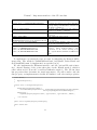
B=g(A) are not allowed at the same time. Table 2.1 shows the most important members of the Var class, which is used to keep variables in the evaluator.
One important feature of the Var class is that it implements the INotifyPropertyChanged interface, which enables it to notify data consumers of changed values.
Table 1. Members of the Var class
public string Name
public Expression Expr
public Expression Result
public bool Valid
public event PropertyChangedEventHandler
PropertyChanged
The name of the variable.
The expression assigned to the variable.
Result of evaluation of the variable.
Indicates whether the result is valid.
Event from the INotifyPropertyChanged
interface, which must be implemented in
order to use this class as a data source.
Evaluator is a computational engine that keeps a set of named expressions
and maintains dependencies between them, ensuring that when one expression
changes, all dependent expressions get reevaluated. It also maintains the expression set in a consistent state by preventing creation of circular dependencies and
by deleting all dependent expressions of a deleted expression.
3. Design goals
The requirements placed before the Geometrijica framework are the following:
• Mathematical notions that can be drawn on paper, such as points, lines,
circles and graphs of functions, can be shown on screen. For example, by
defining a variable M=Segment(A, B) we are also creating a graphical
representation of the segment M, which is drawn on screen. When the
value of the variable changes, the image on the screen also changes.
• Geometrical drawing is a 2D image, consisting mostly of (but not
limited to) geometrical shapes, such as points, lines and circles. It is
kept in computer memory as a list of visual elements with their respective
coordinates and other properties, such as color, size and border width.
• Any property of a visual element can be bound to any variable of the
appropriate type. For example, the location of a point in the Cartesian
coordinate system can depend on a variable of the type Point. When
the value of the variable changes, the position of the visual element is
updated on the screen.
68
• Visual elements can represent geometrical shapes, mathematical notions, but they can also be controls, such as buttons, check boxes or sliders. They are implemented by inheriting from WPF controls and user
controls, or by inheriting from System.Windows.FrameworkElement. Existing functionality of inherited controls is retained.
• Dependency properties of WPF user controls can be bound to any variable of the appropriate type. Data types are converted by special converter classes. For each pair of types there exists a converter class that
provides conversion between them. This enables creation of rich visual
representations, which can be controlled by expressions from the evaluator. For example, one can develop a user control that displays a traffic
light, with a property that specifies which light is on, and then animate
the lights by binding the property to a variable in the evaluator.
• GeoCanvas is a WPF control that displays geometrical drawings. GeoCanvas inherits from System.Windows.Controls.Canvas. The part of the
2D plane that is shown inside the GeoCanvas is specified by the coordinates of the lower left and upper right corners. The area displayed in the
GeoCanvas can be panned and zoomed.
• GeoCanvas supports both screen coordinate system and geometrical Cartesian coordinate system. Visual elements that are placed on a GeoCanvas
decide which coordinate system they will use. Objects using screen coordinates do not move when the geometrical coordinate system moves.
This facilitates mixing of user interface elements with the elements of a
geometrical drawing.
4. Implementation
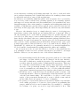
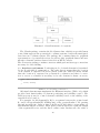
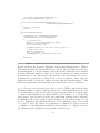
4.1. System overview. The structure of a program built on the Geometrijica
framework is shown in Fig. 4.1. The scope of this discussion is limited to the Visuals, Conversion and Algebra packages, which correspond to appropriate namespaces in Geometrijica.
The Algebra package contains classes discussed in the section ”Expression
evaluator and parser”. A partial list of the classes is shown in Table 4.1.
Table 2. A partial list of classes in the Algebra namespace
Number, String, Logical, EColor
Neg, Plus, Times
Sqrt, Power, Sin, Cos
EPoint, Segment, Line, Circle
Evaluator
Var
Data types
Arithmetic operations
Mathematical functions
Geometrical shapes
Calculation engine
A variable, used in the calculation engine
69
Figure 1. Overall structure of a system.
The Visuals package contains the GeoCanvas class, which is a special Canvas
control that supports the geometrical coordinate systems, besides the usual pixelbased screen coordinate system. The package also contains classes for graphical
representation of geometrical notions, as well as other graphical classes and user
interface elements, such as classes derived from WPF controls.
The Conversion package contains converters which perform data type conversions
necessary for data binding.
4.2. Interfaces and enums. Positioning mode of visual elements is determined
by the LocationMode enumeration. The value Screen means that the location
of an element is expressed in screen pixels, while the value Geometry means
that the location is expressed in geometrical coordinates and that a conversion to screen coordinates is necessary before the element is drawn on screen.
public enum LocationMode
{
Screen, Geometry
}
Listing 1. LocationMode enumeration
All visual elements must implement the IElement interface (Table 4.2), which
provides basic functionality for element positioning and visibility control. The
Valid property is used to control element’s visibility based on the validity of the
expression it is bound to.
For example, let M=Segment(A, B) be a segment between the points A and
B, and P=Perpendicular(M, M.Midpoint) a line perpendicular to M, passing
through its midpoint. Suppose that both M and P have their corresponding visual elements shown on screen. Then, if the points A and B are equal, the length
of the segment M is zero and the line P cannot exist. In that case, the value of
70
the variable P in the evaluator will be marked as invalid, and the visual element
corresponding to P should not be drawn. This is accomplished by binding the
Valid property of the visual element to the Valid property of the variable in the
evaluator.
Table 3. Members of the IElement interface
GeoCanvas GeoCanvas
bool Valid
public Expression Result
bool Visible
void CalcScrLocation()
The GeoCanvas object this element belongs to. Elements use
this reference to obtain information about geometrical coordinates in the GeoCanvas.
Determines whether the element is valid, i.e. whether it should
be drawn.
Result of evaluation of the variable.
Controls visibility of the element.
Calculates and updates the location of the visual element on
the screen.
private GeoCanvas _geoCanvas;
public GeoCanvas GeoCanvas
{
get { return _geoCanvas; }
set { _geoCanvas = value; }
}
public void CalcScrLocation()
{
if (GeoCanvas != null)
{
switch (LocationMode)
{
case LocationMode.Geometry:
ScrLocation = GeoCanvas.Geo2Scr(Location);
break;
case LocationMode.Screen:
ScrLocation = Location;
break;
}
}
}
(code omitted)
Listing 2. A typical IElement implementation in a visual element class
The ILocation interface (Table 4.3) should be implemented by visual elements
which can choose the positioning mode between LocationMode.Screen and LocationMode.Geometry. Most visual elements that represent geometrical shapes do
not implement this interface. On the other hand, user interface elements such as
buttons, check boxes and sliders, which can be placed either on fixed location on
screen or bound to geometrical coordinates, implement the ILocation interface.
71
Table 4. Members of the ILocation interface
Point Location
LocationMode LocationMode
Location of the visual element, either in screen or geometry coordinates.
Specifies how the element’s location is interpreted.
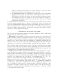
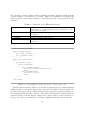
4.3. GeoCanvas. The GeoCanvas class extends the System.Windows.Controls.Canvas
class. It represents a view of a 2D plane in the Cartesian coordinate system.
GeoCanvas has four properties, named X0, Y0, X1 and Y1, which determine the
region of the 2D plane that is shown on the GeoCanvas.
Visual elements are added to the GeoCanvas by calling the RegisterVisual
method.
The Geo2Scr method is used to convert geometrical coordinates into screen
coordinates. This method is called by child visual elements, when they are requested by the GeoCanvas to determine their locations. Obviously, only the
elements in the ’geometry’ positioning mode use this method.
Figure 2. The GeoCanvas class.
4.4. Dependency properties and data binding. The main idea in our work
is to create visual elements which react dynamically to changes in expression
values in the evaluator. WPF data binding [7] provides a simple and consistent
way of binding elements to data sources, such as databases, XML documents,
CLR objects etc.
In our case, data sources are evaluator variables (objects of type Var, Table 2.1). These objects implement the INotifyPropertyChanged interface, which
takes care of notifying the WPF infrastructure when a property of a variable
72
changes. Typical scenario is as follows. When a visual element is created, its
properties are bound to the appropriate properties of the corresponding Var object. The visual element is then placed on a GeoCanvas and thus displayed on
screen. Each subsequent change of Var object’s properties causes the data binding infrastructure to change corresponding properties of the visual element, which
is displayed immediately on screen. For this purpose, one-way data binding is
used.
Since the data types used in the Evaluator are different from those used in the
visual elements, converters must be implemented for each pair of data types for
which data binding is meaningful. Listing 3 shows the EPointConverter class,
which converts values of type EPoint into values of type Point.
[ValueConversion(typeof(EPoint), typeof(Point))]
public class EPointConverter: IValueConverter
{
public object Convert(object value, Type targetType, object parameter,
System.Globalization.CultureInfo culture)
{
EPoint ep = value as EPoint;
if ((ep != null) && (targetType.Equals(typeof(Point))))
{
double x1 = ((Number)ep.X).Value;
double y1 = ((Number)ep.Y).Value;
return new Point(x1, y1);
}
else
{
throw new ArgumentException("Invalid type. EPoint expected.", "value");
}
}
public object ConvertBack(object value, Type targetType, object
parameter, System.Globalization.CultureInfo culture)
{ (code omitted) }
}
Listing 3. A partial listing of the DoubleConverter class
Listing 4 shows lines of code that bind the result of the evaluator variable A
to the first point of the segment sg. After this code has executed, all changes in
the result of the variable A will be immediately reflected on the drawing on screen.
sg = new VSegment(new Point(0, 0), new Point(3, 5));
GeoPanel1.RegisterVisual(sg);
Binding bA = new Binding("Result");
bA.Source = Evaluator.Default.Variables["A"];
bA.Converter = new HMS.Geometrijica.Visuals.Conversion.EPointConverter();
sg.SetBinding(VSegment.AProperty, bA);
Listing 4. Binding of an evaluator variable to a visual element
73
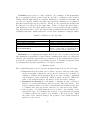
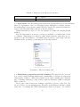
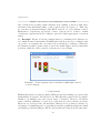
4.5. Visual Elements. Visual elements are objects that are actually drawn on
GeoCanvas. They can be simple dots and lines, or complex drawings. Besides
that, common WPF controls, such as buttons, check boxes and sliders can be
turned into visual elements and placed on GeoCanvas, while retaining all their
functionality. Even complex user controls, with graphical effects and animations
can be turned into visual elements and used.
Figure 3. Visual elements VPoint, VSegment and VButton.
The process of making a new visual element is different depending on what
class is chosen as a starting point. We can start from System.Windows.FrameworkElement
and program everything by hand, or we can start from either Control, UserControl or one of the existing WPF controls and implement only a few necessary
methods. In either case, the IElement interface must be implemented.
4.5.1. Creating a new visual element from FrameworkElement. In this section,
the steps necessary to create a visual element from FrameworkElement will be
explained. The VPoint class represents a geometrical point and it is drawn as a
small circle on screen. The important members of the VPoint class are explained
in Table 4.4.
74
Table 5. Important members of the VPoint class
public GeoCanvas GeoCanvas
The GeoCanvas object this VPoint belongs
to.
private static void RegisterProperties()
Registers dependency properties and their
corresponding event handlers. Called from
the static constructor.
public Point Location
Location of the geometrical point, either in
screen or geometry coordinates.
public LocationMode LocationMode
Specifies how the location property is interpreted.
public double Size
Size of this VPoint in pixels.
protected override void
Called by the WPF when the VPoint needs
OnRender(DrawingContext drawingContext) to be drawn.
private DrawingVisual DrawIt()
Performs actual drawing of the VPoint in
the specified DrawingContext.
public int VisualChildrenCount
Required by the FrameworkElement specpublic void AddVisual(Visual v)
ification. These methods must be impublic int VisualChildrenCount
plemented in all classes deriving from
public int VisualChildrenCount
the System.Windows.FrameworkElement
class.
To implement a geometrical point, we start by inheriting the FrameworkElement class. The methods VisualChildrenCount, AddVisual, DeleteVisual and
GetVisualChild must be implemented as specified in [8].
We also implement the IElement interface, and the optional ILocation interface. Actual drawing of the point takes place in the DrawIt method, which is
called when needed from the overridden OnRender method. The VPoint class
has properties that determine its visual appearance. We will consider only the
Size property, as implementation details are similar for all other such properties.
static VPoint()
{
RegisterProperties();
}
private static void RegisterProperties()
{
FrameworkPropertyMetadata mdSize =
new FrameworkPropertyMetadata(8.0, FrameworkPropertyMetadataOptions.AffectsRender,
new PropertyChangedCallback(OnSizeChanged));
SizeProperty =
DependencyProperty.Register("Size", typeof(double), typeof(VPoint), mdSize);
(code omitted)
}
public static DependencyProperty SizeProperty;
public double Size
{
75
get { return (double)GetValue(SizeProperty); }
set { SetValue(SizeProperty, value); }
}
private static void OnSizeChanged(DependencyObject obj,
DependencyPropertyChangedEventArgs e)
{
VPoint t = (VPoint)obj;
t.DrawIt();
}
private DrawingVisual DrawIt()
{
DrawingVisual vis = (DrawingVisual)visuals[0];
using (DrawingContext dc = vis.RenderOpen())
{
// selection circle
Brush sbr = new SolidColorBrush(Colors.Orange);
sbr.Opacity = SelectionOpacity;
Pen sp = new Pen(sbr, 5.5);
dc.DrawEllipse(null, sp, ScrLocation, Size + 4, Size + 4);
// shape of the point
Brush br = Brushes.Blue;
Pen p = new Pen(br, 2.0);
dc.DrawEllipse(br, p, ScrLocation, Size, Size);
}
return vis;
}
Listing 5. Implementation of the Size property and the DrawIt method
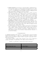
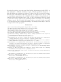
Figure 4.4 shows the sequence diagram for the RegisterVisual method. When a
new visual element (VPoint in this case) is added to the GeoCanvas via the RegisterVisual method, the GeoCanvas control invokes the CalcScrLocation method
from the IElement interface. Since the VPoint in question is in the geometry
positioning mode, it calls the Geo2Scr method of the GeoCanvas, in order to
transform its geometrical coordinates into screen coordinates. After that, the
OnRender method is invoked, which, in turn calls the DrawIt method. This
method performs the actual drawing of the point at the screen coordinates.
4.5.2. Creating visual elements from existing controls. WPF controls already have
full functionality, in other words, they know how to draw themselves and to react
to user interaction, such as keyboard actions and mouse clicks. It is much easier
to create visual elements from existing WPF controls than to code all drawing
and behavior logic by hand, as is the case with visual elements based on FrameworkElement. In order to make a visual element from the Button class, we only
need to implement the IElement interface in the inheriting class. If we want
to be able to place the button on geometrical coordinates, as well as on screen
coordinates, we should implement the ILocation interface too. Figure 4.3 shows
the VButton class, which was created in the described way.
76
Figure 4. Sequence diagram for the RegisterVisual method.
4.5.3. Creating visual elements from UserControl. As WPF controls can be specified in XAML, it is also possible to create visual element in that way. Listing
6 shows the specification of a traffic light control with three controllable lights,
which can be switched on and off by setting the TrafficLight.Light dependency
property. Since the TrafficLight control also implements the IElement interface,
it can be placed on GeoCanvas in the same way as all other visual elements, and
its appearance can be controlled by a variable from the evaluator (Figure 4.5).
<UserControl x:Class="HMS.Geometrijica.Visuals.TrafficLight"
xmlns="http://schemas.microsoft.com/winfx/2006/xaml/presentation"
xmlns:x="http://schemas.microsoft.com/winfx/2006/xaml"
Height="90" Width="30">
<Border BorderBrush="#FFDA1818" BorderThickness="3,3,3,3">
<Grid x:Name="LayoutRoot" Background="#FFDDCECE">
<Grid.RowDefinitions>
<RowDefinition/>
<RowDefinition Height="*"/>
<RowDefinition/>
</Grid.RowDefinitions>
<Grid.ColumnDefinitions>
<ColumnDefinition/>
</Grid.ColumnDefinitions>
<Ellipse Fill="#000000" Stroke="#FF000000" Grid.Row="0" />
<Ellipse Fill="#000000" Stroke="#FF000000" Grid.Row="1" />
<Ellipse Fill="#000000" Stroke="#FF000000" Grid.Row="2" />
<Ellipse Fill="#FFFF3304" Stroke="#FF000000" Margin="3 3 3 3" Grid.Row="0"
x:Name="RedLight" Opacity="100"/>
<Ellipse Fill="#FFDFE22A" Stroke="#FF000000" Margin="3 3 3 3" Grid.Row="1"
x:Name="YellowLight" Opacity="100"/>
<Ellipse Fill="#FF1D8B35" Stroke="#FF000000" Margin="3 3 3 3" Grid.Row="2"
x:Name="GreenLight" Opacity="100"/>
</Grid>
</Border>
77
</UserControl>
Listing 6. Specification of the TrafficLight control in XAML
One benefit from creating visual elements from existing controls is that these
elements retain full functionality of the controls they are based on. This way,
we can mix geometrical shapes with WPF controls on a GeoCanvas control.
Furthermore, dependency properties of those controls can be bound to results
of arbitrary expressions in the evaluator (provided that appropriate converters
exist).
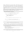
4.6. Example. Figure 4.5 shows a simple window, containing a GeoCanvas control, which in turn contains three TrafficLight controls at screen coordinates, and
one point, one segment and one button at geometrical coordinates. When the
GeoCanvas is resized, panned and zoomed, the traffic light controls retain their
positions, while the other controls’ positions move accordingly.
Figure 5. Point, segment, button and three traffic light controls
on a GeoCanvas.
5. Conclusion
Existing interactive geometry software (IGS) are used in teaching of geometry and
mathematics in general. GeoGebra is one IGS that has gained wide acceptance
thanks to its intuitive use and a great range of features. However, GeoGebra
cannot without difficulty be used as a component in other software products.
Therefore we developed the ’Geometrijica’ framework for geometry software development. A significant part of our framework is the graphical subsystem, which
can display geometrical shapes, WPF controls and user controls at the same time.
78
By using dependency properties and data binding infrastructure in the WPF, we
have managed to link the calculation engine with the graphical subsystem, so
that all changes in calculation results are reflected in the geometrical drawing.
We have also demonstrated that any property of a visual object can be bound
to an arbitrary expression in the calculation engine, which is a step further from
what GeoGebra offers in this respect. Also we have demonstrated how new visual
objects can be made, either by programming them from scratch or by inheriting
existing controls. By following a few simple rules, new visual objects can easily
be created and used in geometrical drawings. Geometrijica can easily be used as
a component in other programs.
References
[1]
[2]
[3]
[4]
[5]
[6]
[7]
[8]
[9]
[10]
[11]
[12]
[13]
[14]
GeoGebra, http://www.geogebra.org (accessed on 8.7.2009)
Cinderella, http://www.cinderella.de (accessed on 8.7.2009)
Cabri, http://www.cabri.com (accessed on 8.7.2009)
Mathematica, http://www.wolfram.com (accessed on 8.7.2009)
Adobe Flash, http://www.adobe.com/products/flash/ (accessed on 8.7.2009)
OpenLaszlo, http://www.openlaszlo.org (accessed on 8.7.2009)
WPF Data Binding - MSDN Library Online, \emhttp://msdn.microsoft.com/en-us/
library/ms750612.aspx (accessed on 8.7.2009)
MacDonald, M., Pro WPF in C# 2008, Apress, 2008.
Hohenwarter, M., GeoGebra - educational materials and applications for mathematics
teaching, PhD thesis, 334 pages, University of Salzburg, Austria, 2006.
Hohenwarter, M. and Preiner, J., Creating mathlets with open source tools, Journal of
Online Mathematics and its Applications. ID 1574, vol. 7. (2007).
Hohenwarter, J., Hohenwarter, M. and Lavicza Z., Introducing Dynamic Mathematics
Software to Secondary School Teachers: the Case of GeoGebra, Journal of Computers in
Mathematics and Science Teaching (JCMST). 28(2) (2009), 135-146.
Hohenwarter, GeoGebra: From car design to computer fonts, M. Informatik-Spektrum.
32(1) (2009), 18-22. Springer.
- ., Numerical mathematics with GeoGebra in high school, Teaching
Herceg, D., Herceg, D
Mathematics and Computer Science, 6/2(2008), 363-378.
- ., Scalar product and numerical integration, Pedago?ka stvarnost,
Herceg, D., Herceg, D
LV, 1-2(2009), 88-102.
Department of Mathematics and Informatics, Faculty of Sciences, Trg Dositeja
Obradovića 4, 21000 Novi Sad, Serbia
E-mail address: [email protected]
Department of Mathematics and Informatics, Faculty of Sciences, Trg Dositeja
Obradovića 4, 21000 Novi Sad, Serbia
E-mail address: [email protected]
79