1
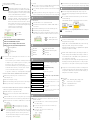
LOGICTECH
USER'S MANUAL
We thank you for purchasing the product, Gyro LTG- 2100T for EP model
Helicopter.
Please read this manual carefully to the end in order for you to use the
product safely and make it work the best.
FEATURES OF PRODUCT
High performance Smart Tail- Lock Gyro for EP model Helicopter which
succeed to the capability of LTG- 6100T.
Zero initializing time.(Tail- Lock mode)
Remove the drift of tail as software solution when changing temperature of
circumstances.
Automatic scan for Transmitter & Receiver types.
(Logictech, Futaba, JR)
Possible to support Digital and Analog Servo at the same time by the
selection function SERVO SPEED.
Support high speed digital Servo.(LTS- 6100G)
Tail- Lock Acceleration function.(Tail- lock performance variable function)
Separate set up of max. Left and right angle of Servo.(Instrumental limit)
Remote Gain control by the GAIN channel.
Self checkup(diagnosis) function.
Provide easy setting method by using of Menu button and Rudder stick
operation to left and right.
High performance rate GYRO for EP model helicopter
Connecting Rudder Channel (Black)
NAME & FUNCTION OF EACH COMPONENT PARTS
1. LED DISPLAY PART
TL
It is composed of 8 pieces of LED and display GAIN in normal times.
Display data selection at present when data setup mode.
SERVO SPEED
Select Servo type.
ROTATE RATE
Select Max. rotate rate.
DIRECTION
Select control direction of Gyro.
SERVO LIMIT
Select Max. left and right angle MENU
of the
BUTTONServo.
2. DATA INPUT PART
MENU BUTTON
Please press it 3 seconds over. Then Menu Mode (Data
selection mode) is activated.
It is used when Moving Menu and input data mixing
with Rudder stick.
SPECIFICATION OF THE PRODUCT
:
:
:
:
:
:
4.5~5.5V(Operating guarantee voltage 5V)
20mA
2 Channels(Rudder, Gain)
1 Channel(Servo Drive)
Remote control by transmitter
Logictech, Futaba, JR Transmitter and Receiver
Data Setting Method
Data Display Method
Dimension
Weight
:
:
:
:
Button press and Stick operation
8 Bit LED Display
22(W)mm x 22(H)mm x 11(D)mm
10g
(PCM, FM Type)
1. SELECT TRANSMITTER DATA
D/R 100%
ATV 140%
SUB-TRIM 0
TRIM 0
2. SELECT RECEIVER TYPE
Please select Trim value to "0" which related to the Transmitter
Rudder Channel. (Important)
Please turn on the power in operating rudder stick to Left or
Right to the end, and waiting for 10 seconds.
And then return the stick to the neutral and again waiting for 5
seconds.
No.
No.
No.
Lighting : status which lighting
Turn on in Tail-Lock Mode.
is Continuous
Flickering: status which is flickering
Turn off in Normal Mode.
LED DISPLAY PART
Operating Voltage
Power Consumption
Input Signal
Output Signal
Gain Control
Compatibility Mode
In Menu Mode(Data setting Mode), Stick operation is utilized
as the data input so Gyro Control is stopped.
Please don't make a flight.
Before flying, Please move to the Gain display mode by pressing
Menu Button. Or automatically let it move to the Gain display
Mode by refrain from DATA BUTTON and Stick operation for 5
seconds.
(Move to the Gain Display Mode if there is no operation for 5 seconds)
(In case of the different Transmitter and Receiver, Transmitter is first)
Connecting Gain Channel (Blue)
Futaba : Gain Channel
JR
: AUX2 Channel or AUX3 Channel
D ISPLA Y PART
Please firmly fix the connector not to move.
Please be careful not to put conducting foreign substances or
flammable substances such as oil, into the product.
Please firmly attach this product.
(It c an be de tache d while it is be ing us e d whe n it is not s ur e ly fix e d.)
Please refrain using in severe circumstances.
(recommend using temperature - 5
~ 35 )
Please don't give the sudden change of temperature.
(e x : war m indoor to cold outdoor)
In case of product installation, surely reference the sticking way of
double side tape.
Please do not disassemble and remodel the product.
Please stop the flight right away when occurrence of any malfunctions
of this product.
Danger
Please select the data of rudder channel as the below(same in Futaba, JR)
Servo connection (Black)
G AIN /DATA
CAUTIONS
THE ORDER OF SETTING
INSTALLATION OF PRODUCT
Please install this product so as to be made horizontality of the mainshaft
with the rotation sensing axis of the Gyro.
Please separate motor 10cm over from the installation place.
(Noise occurred from the motor may have influence on the Gyro function)
Please Install it as closer to the shaft of main rotor as possible.
Please clean up any oil or dust on the installation place.
Please attach it by using of double-sided tape which included.
(Refer to the way of sticking double-sided tape)
LED : LOGICTECH (Prearrangement of its sale)
LED : FUTABA
LED : JR
After finishing of automatic scan,
corresponding LED is flickering
continuously. (Power off-on)
3. SELECT A KIND OF SERVO
Press Menu button so as to light servo Speed LED.
Select a kind of Servo you want to use.
(Refer to the Instruction of basic usage)
No.
No.
No.
LED : Dedicated Digital Servo(LTS-6100G)
LED : Matched Mini Servo
LED : Mini Servo for general
When LTG-2100T is used with the dedicated Digital Servo LTS-6100G.
it is shown to the limits performance.
(LTS-6100G : Speed 0.05 sec/60° , Torque 4.5kg.cm[at 4.8V])
Matched Servo is the most appropriated one to the LTG-2100T Gyro and
show its superior performance than that of general Mini Servo.
Caution - Separate the Gyro Servo Connector when select kinds of Servo.
- When a kind of servo selection is wrong, It can be the reason of
a Helicopter crash by the out of order of Servo or stru
trouble.
4. SELECT GAIN OF THE GYRO
INSTRUCTION OF BASIC USAGE
Please press Menu button for 3 seconds over, then Menu mode is activated.
When pressing the Menu button without moving Rudder stick, Menu is moving
in order of Servo Speed -> Rotate Rate -> Direction -> Servo Limit.
Menu button is pressed When Rudder stick is moved to the Left and right,
Data is increased and decreased.(In neutral status of stick Menu moves to
the next)
When rudder channel of transmitter is Reverse status, Data direction of
increase and decrease is opposition.
There is a relation as the below between the Gyro Gain of the
Transmitter and the real Gain of Gyro.
TL: Light when Tail-Lock mode
No. LED : Gain 0-30%
No. LED : Gain 91-100%
Caution - Some high class controller may could be different with the above way
of display, Please select by the way of correspond to its display.
5. SELECT DIRECTION OF MOVEMENT
9. A Flight
Press Menu button so as to light Direction LED
Transmitter
GYRO
Please check the creation of Tail Roter angle so as to
moving of Helicopter nose to the direction of the Rudder
stick control, If when it is made opposite direction angle,
change the moving direction of the servo by using of Reverse
function of the Rudder channel in transmitter.
At the normal situation in direction of control of the
Transmitter as the above. If the moving direction of Servo
when Rudder stick is moved to right and Helicopter is
turned to the clockwise rotation with the center of the main
shaft is opposite with each other it is normal control status.
If moving of Servo is not normal Please change the moving
direction of Servo in Direction Menu.
(Refer to Instruction of basic usage)
No.
No.
LED : NORMAL
LED : REVERSE
Initial value or same value of Transmitter Rudder Trim should be selected
When you want to flight as Tail-Lock mode in each flying.
If not, Helicopter may could be rotated slow or fast when control the flight
switch.
For getting the best tail stability, raise the gyro gain till the right
before of occurrence Hunting of tail.(Vibrating status to left and right side)
HIGH CLASS FUNCTION
1. ROTATION RATE
Select menu button so as to light Rotate Rate LED.
Please check the D/R and ATV value of transmitter rudder channel to
100% and 140%.
Please select transmitter gain to 65%.(Tail-Lock Mode, gain 30%)
Please taking off slowly and make hovering.
When Rudder stick is operated or returned to the maximum in an instant,
select the "Rotate Rate" value as addition or subtraction so that Tail
THE METHOD OF STICKING DOUBLE-SIDED TAPE
Please stick firmly double sided tape after cutting to Gyro size.
Please pull the Gyro body slightly and stretch tape around 7mm and
release it.
This is to enhance vibration elimination effect by soften the formation
of double sided tape.
(enclosed double sided tape is specially developed for Gyro fixation)
Caution - Too strong pulling of gyro may could be the reason of damage of
double sided tape.
REPAIR PRODUCT
6. SELECT SERVO HORN
Please Select SUB TRIM and TRIM of the Rudder Channel to 0.
Please confirm of NORMAL MODE in Gyro Gain
Please place servo horn vertically by rotation to the control rod.
Please use as Servo horn length as that of Helicopter instruction
CONTROL ROD
SERVO WIRE
Caution - There is in case of selecting SUB Trim of transmitter so as to make
vertical of Servo horn.
In this case neutral signal of some maker's transmitter, when ATV value
is changed in flying, is changed in proportion to the quantity of SUB
Trim selection so the tail may could be rotated slowly.
Please increase and decrease of the pirouette speed by using of D/R.
- If select SUB TRIM in transmitter, it transmit (output) the signal
as stick is moved so Menu selection is impossible.
(If Gyro power is turned off- on, the above phenomenon is disappeared)
7. ADJUSTING LINKAGE NEUTRAL (IMPLEMENTAL NEUTRAL ADJUSTMENT)
Please checking of selection Gyro Gain of transmitter as 35% .
(Normal mode, Gain 30%)
Please take the helicopter off slowly.
Please land it after checking of helicopter slow rotation to left and right.
Please adjust the linkage till the helicopter is not rotate.
No.
No.
(LIMIT value is applied after MENU MODE finishing)
Press Menu button so as to light Servo Limit LED.
Maximize the value of left and right D/R and ATV of Rudder Channel of
transmitter.
Please move rudder stick until the tail roter operation part is not bump
against instrument and in such status save data by pressing Menu button.
Please change the value of D/R and ATV of rudder channel to 100% and 140%
after selection.
No.
No.
LED : Flickering when input of left side data
LED : Flickering when input of right side data
- In case wrong doing of selection Max. operation range of Servo, it can
be the reason of breakage of tail control rod and crash of helicopter
- When setting, please don't make stick control by constraint.It
may could be occurred to damage of Tail control rod and Servo
Gear by moving of Servo to max angle.
LED : Lowest speed rotation
LED : Greatest speed rotation
FACTORY INITIAL DATA
SERVO SPEED
ROTATE RATE
DIRECTION
SERVO LIMIT
No.
No.
No.
Left
LED Mini Servo for General
LED (Minimum acceleration speed)
LED (Normal)
: 25% Right : 25%
THE ORDER OF SETTING
SELECTION OF TRANSMITTER DATA
D/R (100%), ATV (140%), SUB TRIM (0), TRIM(0)
SELECTION RECEIVER TYPE
LOGICTECH, FUTABA, JR
SELECTION KINDS OF SERVOS
Dedicated Digital Servo(LTS- 6100G)
Matched Mini Servo
Analog Mini Servo for general use
SELECTION GYRO GAIN
Normal Mode / Gain 30%
In case of the failure during the normal use of the product, it will
be repaired without any charges.
However when it is failed under abnormal uses, such as falls by
misplacing and misuse, the repair work will be charged.
Please be aware some cases which it is impossible to be repaired
according to its extent of the damage.
When the customer requests the repairs, this company will inspect all
the parts and repair the found damages after receiving it and then it
will have the final test to check whether it has any malfunctions or
not to be returned to the customer.
Since the repair works are don through that complicated process above
mentioned, please send only defective products to us when you request
repairs.(Even for a normal product. Some testing charge can be imposed)
The repair time is various according to the extents of the damages. When
you request the repairs please write down the conditions and symptoms
of the product in details and also inform us with some writing if you
need special wish or needs of this product.
SELECTION MOVING DIRECTION OF SERVO Select Direction menu of Gyro After selection of
transmitter
SELECT SERVO HORN
Select vertically Servo Horn and Tail Control rod
ADJUSTMENT OF LINKAGE NEUTRAL
Adjust linkage till model helicopter not to rotate in
Normal mode, Gain 30%
SELECT MAX. MOVING RANGE OF SERVO
Input data till tail rotor operation part not to bump
against instrument
FLIGHT
Select with the initial value or same value of Rudder
Trim in flight as Tail-Lock mode
8. SELECT MAX. OPERATING RANGE OF SERVO (EXECUTION IN NORMAL MODE)
C au tio n
FM(PPM) Transmitter output unstable signal when a radio wave sending is not
exist so it may could not check stick operation and gain signal normally.
SELF-DIAGNOSIS FUNCTION
LTG-2100T has self-diagnosis function so communicate with users on the
existence of disorder.
In case of disorder of built in sensor or lowering of performance
>> No.1 LED flickering
In case of non-input signal of stick control or abnormal input
>> No.2 LED flickering
In case of non input signal of Gain or abnormal input
>> No.3 LED flickering
PLACE TO SEND.
Address : 976-2, Wolchul-dong, Buk-gu, Gwangju, Korea
Tel
: 82-62-972-9173 , FAX : 82-62-972-9174
E-maill : [email protected]
h t t p : www.logictech.co.kr
This document was created with Win2PDF available at http://www.daneprairie.com.
The unregistered version of Win2PDF is for evaluation or non-commercial use only.