1
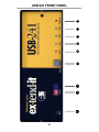
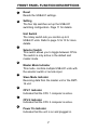
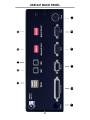
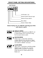
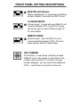
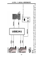
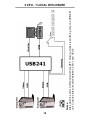
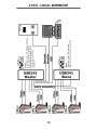
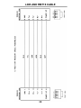
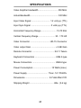
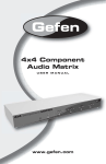
USB•241
USER MANUAL
TABLE OF CONTENTS
Introduction ................................................................... 1
Operation Notes ........................................................... 3
Installation .................................................................... 5
Front Panel Layout ....................................................... 6
Front Panel Function Description ................................. 7
Back Panel Layout ........................................................ 8
Back Panel Function Description ................................. 9
Monitor Dip Switch Settings ........................................ 11
Front Panel Setting Descriptions ........................... 12-13
RMT-16 Remote Control ............................................. 15
Wiring Diagrams .................................................... 16-19
Link and RMT16 Cable ............................................... 20
Specifications ............................................................. 21
Warranty ..................................................................... 23
ASKING FOR ASSISTANCE
TechnicalSupport:
Support:
Technical
Telephone
Telephone
(818) 884-6294
(818) 772-9100
(800) 545-6900
(800) 545-6900
Fax
(818) 884-3108
Fax
(818) 772-9120
Technical Support Hours:
9:00
AM to 5:00
PM Monday
Technical
Support
Hours: thru Friday.
8:00 AM to 5:00 PM Weekdays PST
Write To:
Write To:
Gefen Inc.
C/O Customer Service
Gefen,
Inc.Ave.
6265
Variel
c/o Customer
Service
Woodland
Hills, CA
91367-9897
20600 Nordhoff Street
Chatsworth, CA 91311 USA
www.gefen.com
[email protected]
Notice
Gefen Inc. reserves the right to make changes in the
hardware, packaging and any accompanying
documentation without prior written notice.
USB•241 is a trademark of Gefen Inc.
Macintosh is a trademark of Apple Computer Inc.
© 2001 Gefen Inc., All Rights Reserved
INTRODUCTION
Thank you for purchasing Gefen Inc.’s ex•tend•it USB•241
KVM switcher series. The USB•241 switches your monitor and USB between two computers and is expandable
up to 8 USB•241 units for a total of 16 computers. The
USB•241 switcher is designed to be placed close to the
computers. The USB and Video output of the USB•241
unit can be extended with the ex•tend•it CAT5•2000I USB
product, up to 300 feet away. Alternately, the USB•241
can be switched remotely using the RMT-16 wired remote
control. Video and USB can be extended up to 25 feet
away without the need for an additional amplifier.
The ex•tend•it USB•241 unit can be configured for all types
of monitors and resolutions. Each CPU needs to be configured for the specific monitor size and resolution. For all
new computers from year 2000 and up, the resolution of
the monitors can be adjusted from the control panel of
each computer.
The ex•tend•it USB•241 can be configured for different
modes of switching by setting dip switches on the front
panel. The default model comes with all the switches off.
It allows switching between two CPUs. In order to control
more than two CPUs, the dip switches are set to Master
and an address from 1 to 8 is selected on the selector
switch.
The ex•tend•it USB•241 can be connected together with
other USB•241 units using an expansion cable between
the USB•241 units.
Another useful configuration is for dual monitor switching.
By using two USB•241 units, and a setup for the two units
as Master and Slave configuration, two computers using
two monitors each, can be switched with the USB•241.
1
OPERATION NOTES
READ THESE NOTES BEFORE INSTALLING OR
OPERATION OF THE USB•241 SYSTEM
1. The ex•tend•it USB•241 units were designed to
operate on any type computer with USB keyboard/
mouse and analog video. Using the USB•241
equipment with non USB computers is not
guaranteed or recommended.
2. Powering down an ex•tend•it USB•241 unit while the
computer is on can cause the USB signal to freeze.
It is recommended to always leave the power of the
USB•241 unit ON.
3. The monitor dip switch setting on the ex•tend•it
USB•241 unit needs to be configured to the type of
monitor used. Incorrect dip switch setting will result
in no picture or incorrect picture size upon start up
of the computer. Latest model computers require no
dipswitch setting. See detail on page 11 for
configuration.
4. Selecting Setting switches on the front panel can be
updated during any time of operation. See details on
page 12 & 13.
5. When using a local keyboard in a system that
includes the use of a CAT5•2000S unit and the
USB•241, the USB signal is connected to the
USB•241 directly from the computer. The video is
connected from the CAT5•2000S local monitor out.
3
INSTALLATION
1. Plug the 17v power supply into “POWER” on the back
of the USB•241 then plug the power supply into the wall.
2. Plug the supplied VGA cable into your first computer
and plug the supplied USB cable into your first computer
then plug both cables into “MON1” and “USB1”.
3. Plug the supplied VGA cable into your second computer and plug the supplied USB cable into your second
computer then plug both cables into “MON2” and
“USB2”.
4. Plug your monitor in to “MONITOR”
5. Plug the USB device you want to have switched into
“USB OUT”
5
1
2
2
3
4
55
6
7
8
USB•241 FRONT PANEL
6
FRONT PANEL FUNCTION DESCRIPTIONS
1
Reset
Resets the USB•241 settings.
2
Setting
The four dip switches set up the USB•241
switching configuration. Page 11 for details.
Unit Switch
The rotary switch lets you control up to 8
USB•241 units. Refer to page 12 & 13 for more
details.
3
Selector Switch
This switch allows you to toggle between CPUs.
The switch is only active in the default and
master mode.
4
Master Mode Indicator
This mode controls multiple USB•241 units with
the selector switch or remote input.
5
Slave Mode Indicator
Receiving data from the master unit or the RMT16 unit.
6
CPU 1 Indicator
Indicates that the CPU 1 computer is active.
7
CPU 2 Indicator
Indicates that the CPU 2 computer is active.
8
Power On Indicator
Indicates that the unit is on and plugged in.
7
1
2
3
5
4
7
9
6
8
11
10
USB•241 BACK PANEL
8
BACK PANEL FUNCTION DESCRIPTIONS
1
Remote connector
RJ-11 connector for remoting the RMT-16 remote
control
2
Expansion
DB-25 conncetor type, allows expansion with
additional USB•241 units
3
USB output
Dual type A connector, supports two USB devices
4
Monitor out
HD-15 female connector which interfaces to your
monitor.
5
USB input 2
USB type B connector. Connect to CPU #2
6
Monitor Input 2
HD-15 Male type connects to the CPU#2
7
USB input 1
USB type B connector. Connect to CPU #1
8
Monitor Input 1
HD-15 Male type connects to the CPU#1
9
Dipswitch #2
Resolution selection for CPU#2
10
Power
Connects to an external 17 VAC .7A power supply
11
Dipswitch #1
Resolution selection for CPU#1
9
MONITOR DIP SWITCH SETTINGS
Most new computers come with video drivers that allow
internal configuration of the monitor resolutions from the
control panel. The default setting has ALL DIP
SWITCHES set to the OFF position. Failure in setting
correct dip switches to your monitor type could cause a
black picture or incorrect picture size at the initial
start-up of the computer.
1.
Dip Switches 3 & 6 ON
Use for 640 x 480 Horiz.
Scan Rate: 67KHz
2.
Dip Switches 4 & 6 ON
Use for 640 x 570
Horiz. Scan Rate: 75KHz
3.
Dip Switches 3 & 4 ON
Use for 852x 624
Horiz. Scan Rate: 75KHz
4.
Dip Switches 5 & 6 ON
Use for 1024x768
Horiz. Scan Rate: 75KHz
5.
Dip Switches 3, 4, 5 & 6 ON
Use for 1152 x 670.
Horiz. Scan Rate: 75KHz
6.
Dip Switches 7 & 8 ON
Use for multi res (1600 x 1200)
Monitors. Horiz. Scan Rate: 75KHz
7.
Dip Switches 3, 6 & 7 ON
Use for multi res (1920x 1080)
monitors. Horiz. Scan Rate: 75KHz
8.
All Dip Switches set to OFF
Use for Multi res monitor switch DDC
Horiz. Scan Rate: 75KHz
11
FRONT PANEL SETTING DESCRIPTIONS
SETTINGS
1
2
3
4
Unit Number (1-8)
Selector Switch/ Remote Input
Remote Closure Switch
Slave Mode
Normal / Master Mode
Default Setting for one USB•241 switching two CPUs
with selector switch.
1 DEFAULT MODE
1
2
3
4
Default mode: is used with one USB•241 unit
to switch between CPU-1 and CPU-2 using
the front panel selector switch.
2 MASTER MODE
1
2
3
4
Master mode: is used when controlling
multiple USB•241 units using the front panel
selector switch. The rotary switch is set to the
unit number of USB•241 units used.
3 SLAVE MODE
1
2
3
4
Slave mode: is used when controlling multiple
USB•241 units. The Slave unit is only for
additional CPUs connection. The Remote
mode must be on to receive data from the
Master unit.
12
FRONT PANEL SETTING DESCRIPTIONS
4 MASTER with Remote
1
2
3
4
Master with Remote: is used when controlling
multiple USB•241 units with the RMT-16 unit.
CLOSURE MODE
5 Closure mode: is used with one USB•241 unit
1
2
3
4
to switch between CPU-1 and CPU-2 using
the remote input to switch. Refer to page 18
for more details.
REMOTE MODE
6 Remote mode: Uses the RMT-16 unit to
1
2
3
4
control switching between CPUs. The front
panel selector switch is deactivated.
UNIT NUMBER
Unit Number: is used when controlling multiple
USB•241 units in the master or slave mode. The
number can be set from 1 to 8 units. For each
number assigned, you can control two additional
CPUs. 0 and 9 have no function at this time.
13
RMT16 REMOTE CONTROL
RM T 16
REMOTE CONTROL
3
1
2
4
5
RMT16 FUNCTION DESCRIPTIONS
1
RJ-11 Modular Jack
Interface to the USB•241 remote input.
2
Selector Switch
Sets the counter limit from 1 to 16.
3
Display Window
Shows the current CPU selected.
4
Up Arrow
Up button increments the number showing in
the display window.
5
Down Arrow
Down button decrements the number showing
in the display window.
15
Note:
Settings switch is set for the default mode to switch only one USB•241 unit. Front panel selector is active to switch between CPU-1 and CPU-2
2 CPU - 1 LOCAL - WIRING DIAGRAM
16
17
Notes:
Dip switch is set for 1-4 ON and 2-3 OFF. Dip Switch 1 for Master mode and dip 4 for remote
input ON. Unit number is set to #1 postion, for switching only two CPUs with one USB•241 unit.
Notes:
Set RMT-16 Rotary switch to position #2
2 CPU - 1 LOCAL W/REMOTE
18
Notes:
Dip switch is set for 3 ON and all others OFF. Closure modes is switching only one USB•241
unit. Closure state will switch between CPU-1 and CPU-2.
Notes:
Closure switch in open status, CPU-1 ON
Closure switch in close status, CPU-2 ON
2 CPU - 1 LOCAL W/CLOSURE
Notes:
Dip switch 2 and 4 ON, Slave and
Remote mode. Unit number is set for #2.
Notes:
Dip switch 1 and 4 ON, Master and Remote
Mode. Unit number is set for #1
Keyboard, Monitor and RMT-16
remote is connected to the
master unit.
4 CPU - LOCAL W/REMOTE
19
LINK AND RMT16 CABLE
20
SPECIFICATIONS
Video Amplifier bandwidth ................................ 350 MHz
Actual Bandwidth ...............................................120 MHz
Input Video Signal ............................... 1.2 volt p-p (TTL)
Input Sync Signal ................................. 5 volts p-p (TTL)
Horizontal Frequency Range ......................... 15-70 KHz
Vertical Frequency Range ........................... 30 - 170 HZ
Video Connector ................................. HD-15 Connector
Video output Gain ........................................ +.5 dB Gain
Remote Connector ..................................... RJ-11 Teleco
Keyboard Connectors ................................... USB A type
Mouse Connectors ....................................... USB A type
Power Consumption ...............................15 Watts (max.)
Power Supply .................................. 17vac .7A 115/220v
Dimensions ....................................... 3.2”Hx8.4Wx3.5”D
Shipping Weight ........................................ 6lbs. (3.6 kg)
21
WARRANTY
Gefen Inc. warrants the equipment it manufactures to
be free from defects in material and workmanship.
If the equipment fails because of such defects and
Gefen Inc. is notified within one (1) year from the date of
shipment, Gefen Inc. will, at its option, repair or replace
the equipment, provided that the equipment has not
been subjected to mechanical, electrical, or other abuse
or modifications.
Equipment that fails under conditions other than
those covered will be repaired at the current price of
parts and labor in effect at the of repair. Such repairs are
warranted for ninety (90) days from the day of
reshipment to the Buyer.
This warranty is in lieu of all other warranties
expressed or implied, including without limitation, any
implied warranty or merchantability or fitness for any
particular purpose, all of which are expressly
disclaimed.
The information in this manual has been carefully
checked and is believed to be accurate. However, Gefen
Inc. assumes no responsibility for any inaccuracies that
may be contained in this manual. In no event will Gefen
Inc, be liable for direct, indirect, special, incidental, or
consequential damages resulting from any defect or
omission in this manual, even if advised of the
possibility of such damages. The technical information
contained herein regarding USB241 features and
specifications is subject to change without notice.
All Rights Reserved © Copyright 2001 Gefen Inc.
23
This document was created with Win2PDF available at http://www.daneprairie.com.
The unregistered version of Win2PDF is for evaluation or non-commercial use only.