1
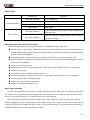
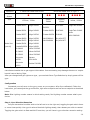
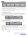
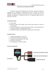
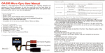
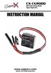
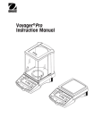
GA-250 Micro Gyro Manual
GA250 Micro Gyro User Manual
v3.0
GA250 is a high-performance advanced AVCS/MEMS gyro, specially designed and optimized for
your RC helicopters. It’s with Very small size and Very light weight. It’s easy in setting, practical
functions, wide scope of applicable servos(Digital only) and superior head-lock performance, even for
your hard 3D application.
Technical Features
²
Sensor: MEMS
²
System control: AVCS (Angular Vector Control System).
²
Dual-gain function: two operational modes can be selected through the transmitter: AVCS mode
and Rate mode.
²
Compatible with all digital servos, include 1520us, 760us and 960us.
Technical Parameters
1. Operating voltage: DC 3.0 ~ 9.0V
2. Operating current: 20mA(At 5.0V)
3. Operating temperature: -15℃ ~ 60℃
4. Dimensions: 21 × 21 × 10mm
5. Weight: 8.0g(Include Connectors and Wires)
Components Functions
Gain Channel Plug(Red)
Tail Channel Plug (Black)
Status LED
Tail Servo Joint
1/4
GA-250 Micro Gyro Manual
Status Light
Status light
Operating Mode
Describe
Blue Fast Flashing
Gyro Calibrating
Steady Blue Light
AVCS Mode
Blue 2 Flashing
Light Down
Red Slow Flashing
Error Codes
Blue Slow Flashing
AVCS Mode, Rudder stick not centered
Rate Mode
Gyro not receiving gain signal. Please checking the
wire and plug
Gyro not receiving rudder signal. Please checking
the wire and plug
Setting Up Your Gyro For The First Time
Follow the steps below in the specified order to successfully deploy your gyro.
◆ Fix the gyro on your model: please stick the gyro to the stable place of the helicopter with the
double-sided adhesive tape. If there is a high vibration environment, please plus a steel plate to
help to reduce the influence.
◆ Connect the gyro to the receiver, don’t connect the tail servo to the gyro at this time.
◆ Ensure that the transmitter trims and sub-trims are set to zero and that collective pitch to tail
pitch mixing is disabled.
◆ Power on your Rx and gyro.
◆ Select the correct servo type as describe in the Servo Type Selection section of this guide.
◆ Power off your gyro.
◆ Connect the servo to the gyro then power on it.
◆ Follow the manual to set the gyro direction, high servo endpoint and low servo endpoint.
◆ Quit setting and back to stand by way.
◆ Adjust gyro gain via your transmitter
◆ Confirm all things and ready to fly.
Servo Type Selection
GA-250 was designed to work with all modern digital tail servos, don’t use any analogy tail servo at
all. There have some different type digital servos, and when use wrong setting, you will broken your
servo or not working correct. so, please do this job in the first step.
Here is the way to access the servo configuration mode. Power on your Gyro and when it Blue
flashing, toggling the gain switch three or more times quickly in your radio. You have Servo Type Setting
mode now. By pull the rudder stick left or right, you got different type. The number and the colors of
flashed indicates the currently selected servo type.
2/4
GA-250 Micro Gyro Manual
Operation
← Move the rudder stick to left
Light
●
Status
Type
1520us / 333Hz
Futaba S9253
Align DS410
Futaba S9254
Align DS420
Futaba S9257
Move the rudder stick to right →
●●
●●●
760us /
1520us /
560Hz
250Hz
Futaba
●●●●
960us / 333Hz
JR 2700G
LogicTech 6100G
Futaba S9251
JR 8700G
LogicTech 3100G
Align DS510
Futaba S9256
JR 810G
Futaba S9650
Align DS520
MKS DS8910
Sky HDS-577
Futaba S3153
Align DS610
MKS BLS980
Sky HDS-877
Model List
Futaba S3154
Align DS620
(not all)
Futaba BLS254
Align DS650
JR 8900G
Hitec 5925MG
JR 3400G
Hitec 6965HB
JR 3500G
Hitec 5083MG
Airtronics
Sanwa
94758
ERG-WRX
Airtronics
94761
BLS251
Hitec
HSG-5083MG
Robbe FS61BB
Note: if your digital tail servo is not listed in the above table, please ask your supplier or visit the
manufacture’s assist site to get support information. Incorrect setting may damage the servo or maybe
loss tail control during flight.
After you changed and got right servo type , you need exit Servo Type Selection by simply power off the
gyro.
Configuration
Connected your tail servo to the gyro, power on your system. After Gyro calibrated. Follow the
instruction, you can adjust the gyro direction, high servo endpoint and low servo endpoint as described
below.
Note: Blue Lighting number means in which setting mode, Red Lighting number means what’s your
choice.
Step 1: Gyro Direction Reversion
Pull your transmitter’s rudder stick to the left end or to the right end, toggling the gain switch three
or more times quickly. Your gyro’s red and blue both lighting steady, then release your stick to neutral.
Toggling the gain switch to Rate and AVCS one time, you will have in gyro direction reversion setting.
3/4
GA-250 Micro Gyro Manual
Operation
← Move the rudder stick to high end
Move the rudder stick to low end →
Light Status
●●
●●●
Gyro Direction
Normal
Reverse
The gyro has two move directions, Normal and Reverse. Rotate the helicopter at least 90 degrees
counter-clockwise, in an attempt to oppose the rotation and maintain the helicopter heading the gyro
should have now moved the tail blades in the same manner as if right rudder was applied, the direction
of the gyro is correct. If its not, please change the setting.
The step above is critical. If the gyro direction is wrong, the helicopter may yaw at high speed and
cause an extremely dangerous situation when taking off!
Step 2: Adjust High Servo Endpoint
When set gyro direction ok, toggling the gain switch to Rate and AVCS one time, you are in Adjust
High Servo Endpoint setting. Using the Rudder stick adjust the servo position until you achieve
maximum tail rotor pitch without binding on the mechanical limits. When satisfied, toggle the gain
switch to Rate and AVCS one time to next setting.
●●●
Light Status
Increase
Pull the rudder stick to high end direction
Decrease
Pull the rudder stick to low end direction
Step 3: Adjust Low Servo Endpoint
Now, you are in Adjust Low Servo Endpoint. Like the High Servo Endpoint setting. Using your
Rudder stick adjust the servo position for maximum tail pitch without binding .
●●●●
Light Status
Increase
Pull the rudder stick to low end direction
Decrease
Pull the rudder stick to high end direction
Now you complete all the setting, you need exit setting mode. By toggling the gain switch to Rate
and AVCS three or more times quickly. Your gyro return the working mode. if you toggling the gain
switch one time, you will return to Gyro Direction Reversion setting.
Note 1: At any process in setting mode, you can exit the setting mode by toggling the gain switch three
or more times quickly.
Note 2: At working mode, when you need recalibrate the gyro anytime, you should toggling the gain
switch three or more times quickly.
Have Fun!
ASSAN Electronic Control Technology Co., Ltd
http://www.assan.cn
4/4