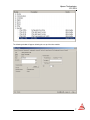
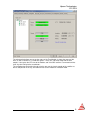
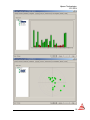
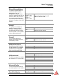
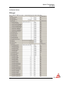
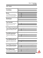
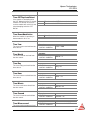
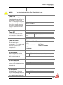
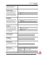
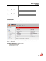
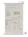
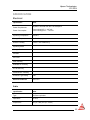
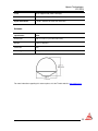
1
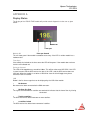
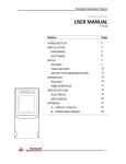
Hiprom Technologies
1/21/2014
1756HP-TIME
USER MANUAL
V2.03.00
Section
Page
INTRODUCTION
2
INSTALLATION
3
HARDWARE
3
SOFTWARE
4
SETUP
5
HARDWARE
5
RSLOGIX
6
OPERATION
15
RSLOGIX
15
WEB INTERFACE
22
1588 PRECISION TIME PROTOCOL (PTP)
23
NETWORK TIME PROTOCOL (NTP)
27
IRIG-B
30
CST AND UTC CONVERSION
31
SPECIFICATIONS
32
ELECTRICAL
32
MECHANICAL
34
APPENDIX
35
A – DISPLAY STATUS
35
B – MESSAGE BLOCKS
37
C – OPERATING MODES
38
1
Hiprom Technologies
1/21/2014
INTRODUCTION
The 1756HP-TIME module provides accurate time synchronization on a number of interfaces
using Global Positioning System (GPS). The module also has the ability to obtain time from
various sources and provide time synchronization on other, thus acting as a gateway between
different time synchronization methods.
Time synchronization can be done using the Allen-Bradley ControlLogix backplane (CST and
UTC conversion), IRIG-B-122 (OUT and IN), Ethernet Precision Time Protocol (PTP) and
Ethernet Network Time Protocol (NTP).
The module also provides GPS position in XYZ Cartesian ECEF (Earth Centered, Earth Fixed)
and LLA (latitude, longitude and altitude). Velocity (m/s) is also provided in XYZ Cartesian ECEF
and ENU (East-North-UP). When using an external antenna the module can provide has
precision position (2.5mm).
This document serves to describe the functionality, installation, configuration and operation of the
module.
2
Hiprom Technologies
1/21/2014
INSTALLATION
Hardware
The 1756HP-TIME module is designed to operate within the Allen-Bradley ControlLogix platform.
All power required for the module’s operation is derived from the ControlLogix backplane.
LED and LCD status
information
Ethernet Port 2
Ethernet Port 1
GPS SMA connector
1756HP-TIME Front View
IRIG-B coaxial
connector
LED and LCD information
All information regarding the module status, pulse per second (PPS), IP address etc. will be given
via the LCD and LED indicators. Please view Module Status section for more information.
Ethernet Port 1 and Ethernet Port 2
PTP and NTP time synchronization is done via the dual port switch.
The switch supports a Device Level Ring (DLR) which can be used to ensure a failsafe Ethernet
Ring.
NOTE:
This port is not a bridge to the backplane and cannot be used to view
modules on the backplane.
GPS SMA Connector
This connector is used to connect the GPS bullet antenna. The installation of this antenna will be
explained later in this section.
IRIG-B coaxial connector
The IRIG-B coaxial connector is used to connect the module to an IRIG-B network. Depending on
the module configuration it can be a Master or Slave on the IRIG-B network.
3
Hiprom Technologies
1/21/2014
Rotary switches
DIP switches
1756HP-TIME Top View
Rotary switches
The rotary switches are used to select certain options on the Ethernet interface of the 1756HPTIME module. The settings will be explained in the Module Configuration section.
DIP switches
These are used to select certain general operation options for the module. The settings will be
explained in the Module Configuration section.
GPS Antenna installation
The bullet antenna must be installed with a clear view of the sky (nothing obstructing the view of
the antenna to the sky). If an antenna is installed with a limited view of the sky the GPS receiver
will either have a low satellite lock count or will not be able to obtain lock. This will result in low
accuracy time synchronization.
Software
The user will need the following software to configure and use the 1756HP-TIME:
• RSLogix 5k ladder example code
• Add-on Profile (AOP)
Both the applications can be found on the product CD or the Hiprom Technologies website:
www.hiprom.com
4
Hiprom Technologies
1/21/2014
SETUP
Hardware
Rotary switches
With zero at the top of the rotary switches the digits will be entered from left to right. For example
if you were to select 345 on the switches it would be done as shown below:
Below are the options that can be selected:
Switch
1 – 254
888
900
Description
When values between 1 and 254 are selected the module will default to an
IP address 192.168.1.X, where X will be the value of the rotary switches
selected.
This will set the module to reset all settings to Out-of-the-box.
BOOTP will be selected which removes the current IP address. The new IP
address must be set with a BOOTP server.
DIP switches
The switches are numbered as shown below:
Switch
1
2
3
4
Description
This is used for debugging the module. The user must never set this.
This is reserved for future use.
This is reserved for future use.
The user can select if the battery must be connected to the GPS receiver
5
Hiprom Technologies
1/21/2014
and keep the last satellite data. This will help to speed up the process of
getting GPS Lock when the module is rebooted if power was lost.
SAFE MODE
The module has the option to run the firmware that it was originally shipped with. This can be
used in the case where the power was cycled whilst flashing the firmware. Thus if the module
does not boot because of the corrupted firmware the user can set the module into safe mode and
re-flash the module. The Safe Mode jumper is located under the front cover as shown below:
NOTE:
The module must be placed back into non-SAFE MODE to avoid running
old firmware even if the module has been flashed with new firmware.
RSLogix
This section describes the procedures required to configure the 1756HP-TIME module within the
Logix platform.
NOTE:
Each 1756HP-TIME module must be owned by a single Logix Controller.
The user must select the GPS TIME Module in RSLogix when adding the module to the IO tree in
RSLogix 5k.
In order for this option to be available the Module AOP must be installed. The installer can be
found on the accompanying CD or alternatively can be downloaded from the Hiprom technologies
website: www.hiprom.com
6
Hiprom Technologies
1/21/2014
The following window will appear allowing the set up of the time module.
7
Hiprom Technologies
1/21/2014
Clicking on the configuration tab allows one to set the time source, the output time format as well
as other CIP sync settings and descriptions.
8
Hiprom Technologies
1/21/2014
The advanced tab allows one to see the status of the Time Module. It shows the source of the
time, as well as whether it is a valid time (green – valid, red – not valid) along with the time
outputs. It also gives the UTC time of the module, and if the GPS antenna is connected and has
clear sky view it will give the co-ordinates.
The navigation tree to the left of the tab also lets one see the signal strength of the satellites as
well as the position in the sky, and allows one to set the module in simulation mode.
9
Hiprom Technologies
1/21/2014
10
Hiprom Technologies
1/21/2014
The following configuration tags can all be set from within the AOP, descriptions of each of the
configuration parameters follow.
Source
This indicates to the module
what will be used as the time
source. The values to the right
are for each time source
provided.
1
2
3
4
5
GPS
IRIG-B
PTP
NTP
External
0
1
1588 PTP output is disabled
1588 PTP output is enabled
0
1
NTP v3 RF(1305) output is disabled
NTP v3 RF(1305) output is enabled
CIPSyncOutputEnable
When this bit is set the module
will enable PTP synchronization
on Ethernet. Thus the module
will be a master or source.
NTPOutputEnable
When this bit is set the module
will enable NTP on Ethernet.
Thus the module will be a master
or source.
11
Hiprom Technologies
1/21/2014
IRIGBOutputEnable
When this bit is set the module
will enable IRIG-B on the coaxial
interface. Thus the module will
be a master or source.
0
1
IRIG-B-122 output is disabled
IRIG-B-122 output is enabled
0
1
Module will stop sending IRIG-B when lock is lost
Module will continue sending IRIG-B even when
lock is lost
0
1
UTC time base used is for V16 and newer
UTC time base used is for V15 and older
0
1
Module will not attempt to be the CST Master
Module will attempt to be the CST Master
IRIGBLockLostTX
When this bit is set the module
will keep sending an IRIG-B
signal even when it has lost lock
to the time source. If this bit is
clear the module will stop
sending a valid IRIG-B signal
when it has lost lock with the
time source.
PreV16Support
If the user is using RSLogix 5000
v16 and newer the UTC time
base is different from previous
versions of RSLogix. To ensure
that ControlLogix PLC’s running
different versions can be time
synced using the 1756HP-GPS
module the user must select if
v16 and newer is used or not.
CSTMastershipEnable
The bit indicates if the module
will be the CST Master on the
local rack (if no other CST
Masters are currently active).
Thus when set the module will
attempt to be the CST Master.
NTPUpdateInterval
The time (in seconds) at which
the module will request an
update of the time from the NTP
server.
Allowed values:
5
30
300
3600
86400
604800
5 seconds
30 seconds
5 minutes
1 hour
1 day
1 week
12
Hiprom Technologies
1/21/2014
ExternalSourceAddress
The external source address is
used for one of two sources
depending on how the
configuration is set. If the time
source is set to NTP then this will
be the IP address of the source
that must be used. If the source
is set to External GPS then this
will be the IP address of the GPS
receiver.
Example:
Byte 0 = 192
Byte 1 = 168
Byte 2 = 1
Byte 3 = 100
The module will used external IP
address: 192.168.1.100
Priority1
The priority is used to force a
module to become the time
master on a network where it is
not necessarily the best source
of time. Default is 128, any lower
values indicate preference.
Priority2
This is used to break a tie
between two modules with the
same priority 1 value.
Default:
128
Values lower than 128 indicate
preference on the network
Default:
128
Values lower than 128 indicate
preference on the network
CIPSyncTimeToLive
A mechanism that limits the
lifespan of data in a network.
It prevents the TCP packet
from circulating indefinitely.
CIPSyncInterval
The time interval that the module
will send out a PTP sync packet.
AdvancedConfig
Example:
1
Allowed Values:
1/8
1/4
1/2
1
2
The packet will circulate once
125 milliseconds
250 milliseconds
500 milliseconds
1 second
2 seconds
These are various bits used to
set certain options in the module.
Bit:
0
1 - 31
Demo Mode
Reserved
DemoWeekNumber
Example:
29 April 2010
Week number = 1581
13
Hiprom Technologies
1/21/2014
When the module is in demo
mode this can be used to set the
initial date to be used by the
module. The week number is the
week count since 6 Jan 1980.
DemoWeekSeconds
This is the amount of seconds
that have passed since the
beginning of the week. The
seconds count begins with 0
each Sunday morning at
midnight GPS time.
Example:
Sunday 1am
Week Seconds = 3600
Example:
1756HP-TIME
Example:
RemoteRack_Slot4
UserName
Helps to identify the time
module, visible in CIPSync
syncronisation.
UserLocation
Can be used to provide extra
information helping to identify the
location of the module
14
Hiprom Technologies
1/21/2014
OPERATION
RSLogix
Each 1756HP-TIME consumes 1 connection from the Logix Controller.
15
Hiprom Technologies
1/21/2014
INPUT IMAGE
CommStatus
This is reserved.
This is reserved
This indicates the current time
source. The values to the right are
for each time source provided.
1
2
3
4
5
ModuleStatus
This is reserved
Source
This is reserved.
GPS
IRIG-B
PTP
NTP
External
Time.TimeValid
When this bit is set a valid time is
being received from the time
source.
0
1
Time being received from source is invalid
Time being received from source is valid
0
1
1588 PTP output is disabled
1588 PTP output is enabled
0
1
NTP v3 RF(1305) output is disabled
NTP v3 RF(1305) output is enabled
0
1
IRIG-B-122 output is disabled
IRIG-B-122 output is enabled
0
1
Module will not attempt to be the CST Master
Module will attempt to be the CST Master
0
1
Module is not the CST Master
Module is the CST Master
Time.CIPSyncOutputEnable
When 1588 Output PTP has been
enabled in the config this will be
set.
Time.NTPOutputEnable
When NTP Output has been
enabled in the config this will be
set.
Time.IRIGBOutputEnable
When IRIG-B Output has been
enabled in the config this will be
set.
Time.CSTMasterEnabled
When the module will attempt to be
the CST Master this will be set.
Time.CSTMastership
If the module is the CST Master on
the local rack then this bit will be
16
Hiprom Technologies
1/21/2014
set.
Time.CSTDuplicateDetect
If the module is attempting to be
the CST Master but there is already
another CST Master on the local
rack the module will set this bit and
stop attempting to be the CST
Master.
Time.DemoModeActive
When the module is operating in
demo mode this bit is set.
Time.Year
The current year received from the
time source.
Time.Month
The current month received from
the time source.
Time.Day
The current day received from the
time source.
Time.Hour
The current hour received from the
time source.
Time.Minute
The current minute received from
the time source.
Time.Second
The current second received from
the time source.
Time.Microsecond
The current microsecond received
0
1
There is no other CST Master on the local rack
There is another CST Master on the local rack
0
1
Demo Mode is inactive
Demo Mode is active
Example:
27/04/2010
13:45:22 – 234567us
Example:
27/04/2010
13:45:22 – 234567us
Example:
27/04/2010
13:45:22 – 234567us
Example:
27/04/2010
13:45:22 – 234567us
Example:
27/04/2010
13:45:22 – 234567us
Example:
27/04/2010
13:45:22 – 234567us
Example:
27/04/2010
13:45:22 – 234567us
Year = 2010
Month = 4
Day = 27
Hour = 13
Minute = 45
Second = 22
Microsecond = 234567
17
Hiprom Technologies
1/21/2014
from the time source.
NOTE:
The time is only valid if the Time.TimeValid bit is set.
Time.UTC
This is the current UTC
(Coordinated Universal Time) in
microseconds since the time
base. The time origin is based on
pre- or post RSLogix v16. Please
refer to the example code how
this can be used to time-stamp
events in Sequence-of-Events
(SOE) modules.
Time.CST
Example:
30 April 2010
06:23:41:377069us
UTC = 1209536621000000
This is the current CST of the
local rack (depending on the
CST Master) in microseconds.
Example:
CST Master
running for 1
hour
Time.CSTOffset
Example:
CSTOffset = UTC - CST
This is the difference between
the UTC and CST in
microseconds. This can be used
to set the wallclock in the
controller. Please refer to the
example code.
CST = 3600000000
UTC =
1209536621000000
CSTOffset =
1209533021000000
CST =
3600000000
GPS.GPSLock
When using GPS as the time
source this bit will indicate if the
GPS receiver has lock.
0
1
GPS receiver does not have lock
GPS receiver has locked onto sufficient satellites
0
1
The antenna is either no present to faulty
The antenna is connected correctly
0
1
PDOP is currently active
PDOP is not active
GPS.AntennaOK
When using GPS as the time
source this bit will indicate if the
antenna is connected and is
opertational.
GPS.PDOPOk
Position Dilution of Precision
occurs when although there are
sufficient satellites in lock, 2 or
more of them appear to occupy
18
Hiprom Technologies
1/21/2014
similar positions in the sky and
thus the number of effective
satellites is decreased.
GPS.WarmStart
This bit will indicate if the GPS
receiver had battery backup
when the power was lost. A
warm start will significantly help
to reduce the time at startup to
get lock on sufficient satellites.
0
1
GPS receiver did not have a warm start
GPS receiver had a warm start
0
GPS receiver is not receiving differential
corrections
GPS receiver is receiving differential corrections
GPS.DGPS
This bit will only be valid when
using an external GPS. If set the
GPS receiver is receiving
differential corrections which will
improve the position accuracy.
1
GPS.PPS
The pulse per second toggles at
the exact moment the second
changes and the microseconds
are zero. Note that because the
RPI is 10ms the accuracy is lost
in the input image.
GPS.FaultCode
This is reserved.
GPS.Mode
This is reserved.
0
1
It has been more than 100ms since the last
second roll-over pulse
It has been less than 100ms since the last second
roll-over pulse
This is reserved.
This is reserved.
GPS.SVCount
The number of satellite vehicles
that the GPS receiver is locked
on.
GPS.Latitude
Current position Latitude in
degrees.
This will be a number between 0 and 12
Example:
S26°05’17.0”
E28°00’21.3”
Elev: 1577m
Latitude = -26.088087
Example:
19
Hiprom Technologies
1/21/2014
GPS.Longitude
Current position Longitude in
degrees.
GPS.Altitude
Current position Altitude in
meters.
GPS.PositionX
Distance from Earth-centre along
the X – axis in meters.
GPS.PositionY
Distance from Earth-centre along
the Y – axis in meters.
S26°05’17.0”
E28°00’21.3”
Elev: 1577m
Example:
S26°05’17.0”
E28°00’21.3”
Elev: 1577m
Example:
S26°05’17.0”
E28°00’21.3”
Elev: 1577m
Example:
S26°05’17.0”
E28°00’21.3”
Elev: 1577m
Distance from Earth-centre along
the Z – axis in meters.
Example:
S26°05’17.0”
E28°00’21.3”
Elev: 1577m
GPS.RelativePositionX
This is reserved.
GPS.PositionZ
This is reserved.
GPS.RelativePositionY
This is reserved.
GPS.RelativePositionZ
This is reserved.
Longitude = 28.00586
Elevation = 1577
ECEF X = 5062108.5
ECEF Y = 2692197.3
ECEF Z = -2788525.8
This is reserved.
This is reserved.
GPS.VelocityNorth
A negative value indicates southerly direction of movement.
Current Northerly Velocity in
meters per second (m/s)
Only applicable with GPS as the time source.
GPS.VelocityEast
A negative value indicates westerly direction of movement.
Current Easterly Velocity in
meters per second (m/s)
Only applicable with GPS as the time source.
20
Hiprom Technologies
1/21/2014
GPS.VelocityUp
Current Upward Velocity in
meters per second (m/s)
A negative value indicates downward direction of movement.
GPS.VelocityX
The X-axis is defined as the vector with origin at the earth's
centre and passing through the intersection of the equator and
Greenwich meridian.
Speed with respect to the X –
axis in meters per second (m/s)
GPS.VelocityY
Speed with respect to the Y –
axis in meters per second (m/s)
GPS.VelocityZ
Speed with respect to the Z –
axis in meters per second (m/s)
Only applicable with GPS as the time source.
The Y-axis is defined as the vector with origin at the earth's
centre in the same plane as the X-axis, at 90°
The Z-axis lies at a 90 angle to the equatorial plane and
extends through the North Pole.
OUTPUT IMAGE
IRIGYear
We the module has a IRIG-B
time source the year must be
provided in the output image as
the year is not passed over IRIGB. Thus the user must enter the
current year.
Example:
30 April 2010
IRIGYear = 2010
UTC_Offset
The UTC_Offset is only used
when the time source is IRIG-B
and PTP output is enabled. IRIGB provides the UTC time while
PTP requires TAI (International
Atomic Time). The difference
between the two is the UTC
offset.
Example:
30 April 2010
UTC_Offset = 34
* The user will need to see what is the current UTC Offset
as it changes approximately every 18 months.
21
Hiprom Technologies
1/21/2014
ReferencePositionX
This is reserved.
This is reserved.
ReferencePositionY
This is reserved.
This is reserved.
ReferencePositionZ
This is reserved.
This is reserved.
Web Interface
The web interface can be used from any PC that has a web browser. It will provide all the
diagnostics of the module as well as each field device as shown below:
The web interface can be accessed by entering http:// IP address into the address bar of the
browser as shown below:
Eg. 1756HP-TIME IP address: 196.135.145.234
22
Hiprom Technologies
1/21/2014
1588 PRECISION TIME PROTOCOL (PTP)
The 1756HP-TIME module supports 1588 PTP which allows for high precision time
synchronization over an Ethernet network.
NOTE:
RSLogix v18 and newer will support 1588 PTP. This is not supported in the
previous versions.
NOTE:
The 1756HP-TIME module supports PTP version 2.
Time Module as a PTP Master
PTP will be used to synchronize Rockwell devices supporting this protocol. To configure the PTP
settings of the module the CIP Sync object must be used. Please refer to the CIP documentation
for more detail on how to use this object.
When receiving sufficient satellites the 1756HP-TIME module can synchronize devices to within
100ns (using 1588 PTP) when connected directly to the device that is being synchronized. If
these devices are connected via a switch that does not support 1588 PTP the time
synchronization will degrade as there are more random delays which will affect the mean delay
time calculation used for time synchronization. Thus the more switches and/or interfaces between
the 1756HP-TIME module and the device being synchronized, the bigger the spread of random
time delays which will result in lower time sync accuracy.
If the user has enabled PTP on the EN2T / EN2TR then it will automatically look for any other
1588 PTP devices and determine who has the highest quality clock. Once this is done it will
automatically sync to this clock.
NOTE:
1588 PTP uses a multicast address thus switches must be setup to allow
multicast or have IGMP enabled.
The EN2T / EN2TR are boundary clocks which mean they can be a time “slave” on one interface
and a time “master” on another. Thus they can act as a transparent gateway when a Logix
Controller uses the time Grand Master which might be on Ethernet (1756HP-TIME). The EN2T /
EN2TR must have CIP Sync and Motion enabled as shown below. In the Date/Time page of the
controller under Time Synchronize there is a tick box Enable Time Synchronization. If this is set
the Controller will look for the highest quality clock on the backplane. If there is an EN2T / EN2TR
in the local rack that is synchronized to a 1756HP-TIME the Logix Controller will synchronize to
the 1756HP-TIME module via the EN2T / EN2TR.
Below are screen grabs of the Date/Time tab in the controller as well as the CIP Sync page which
is launched from the Advanced button.
NOTE:
Most devices supporting 1588 PTP defaults to PTP Enabled: FALSE. PTP
must be enabled on the devices before time synchronization will start.
Please refer to 1756HP-TIME PTP implementation.doc for implementation details.
23
Hiprom Technologies
1/21/2014
24
Hiprom Technologies
1/21/2014
25
Hiprom Technologies
1/21/2014
Time Module as a PTP Slave
The 1756HP-TIME module can be set to be a PTP slave. It will automatically synchronize to the
best PTP clock on the Ethernet network, using the best master clock algorithm (BMC).
NOTE:
The TIME module cannot act as a boundary clock. If PTP is selected as the
input time source, then PTP output will be disabled.
Using PTP as the time source enables NTP and IRIG-B as the output modes. Thus the accuracy
is limited to the accuracy of the respective output modes.
NOTE:
The accuracy of the PTP time is dependent on the quality and reliability of
the Ethernet network. The PTP algorithm allows for network delays, but
needs a constant delay to synchronize accurately. PTP switches prioritize
PTP messages to keep the delay constant, and are therefore preferred for
PTP networks.
26
Hiprom Technologies
1/21/2014
NETWORK TIME PROTOCOL (NTP)
Time Module as an NTP Server
The 1756HP-TIME module supports the Network Time Protocol (NTP) which allows for time
synchronization over an Ethernet network. NTP clients can be synchronized to around 1ms of the
NTP client depending on the network.
NTP is generally used when synchronizing personal computers or domain controllers. The user
can use the supplied application (HSNTP) to set the Windows Time Service to synchronize to the
1756HP-TIME module.
NOTE:
The 1756HP-TIME module supports NTP v3 RFC1305.
NOTE:
When a PC is on a domain it will try and synchronize to the domain
controller. Thus the user can setup the domain controller to synchronize to
the 1756HP-TIME.
Below is a screen grab of HSNTP which can be used to synchronize a PC to the 1756HP-TIME.
•
•
•
•
•
Before the user can synchronize the current PC to the NTP source the user will need to
enter the IP address of the NTP source. In the example the IP 192.168.1.100 is used;
which will be the IP address of the 1756HP-TIME module. Once the user has entered the
IP address the Set button must be pressed to update the data.
The update interval is the time interval at which the NTP client will try and synchronize it
time with that of the NTP server. The user must press the Set button to save the
changes.
Once all the above changes have been made the user will need to Stop and Start the
Windows Time Service to allow it to load the new settings.
Once the user has entered the correct destination IP address the Sync button can be
pressed to immediately synchronize the time with the NTP server.
The user can set all the changes made back to defaults by clicking the Set button next to
Resort to defaults.
27
Hiprom Technologies
1/21/2014
Time Module as an NTP Client
The 1756HP-TIME module can be configured to connect to an external NTP source (the module
can also accept SNTP as a time source protocol), and then output the time on the backplane, as
PTP or IRIG-B time.
To configure the module to connect to an NTP source, open the module properties box and select
the configuration tab as shown in the diagram above. In the ‘Source Settings’ drop-down box
select NTP as the source. Once this is selected the ‘External Source Address’ and ‘NTP Update
Interval’ options become available.
The external source address is the IP address of the NTP source; the NTP update interval
specifies how often the time module will discipline its internal clock to the NTP source. The
update interval can range from 5 seconds to 1 week.
The frequency of the update interval will affect the accuracy of the time from the module – if the
time is not disciplined by the NTP source the time may drift by up to 10µs/s depending on
external factors such as temperature and humidity.
In order to keep the time as smooth as possible, the time will only be disciplined at a certain rate
until the time is equivalent to the NTP source. This is unless the time of the module becomes
more than 1 second different to the source time. If this occurs, the module will ‘jump’ to the
correct time as given by the NTP source.
28
Hiprom Technologies
1/21/2014
NOTE:
The accuracy of the NTP time is dependent on the quality and reliability of
the Ethernet network. If the update time is set to too high a value the clock
may drift and jump. A recommended value of 30 seconds or less is
recommended for optimal accuracy.
If the module loses connection to the NTP source (this will happen if the source does not reply
after the update interval time has expired) then the ‘lock’ LED will become red and the time
module will run on its internal oscillator until the source becomes available again. The module will
try to reconnect to the NTP source every 10 seconds after a loss of communication.
NOTE:
NTP time as a source is only accuracy to 10 ms therefore the
synchronization accuracy using 1588 PTP will be limited to 10 ms.
29
Hiprom Technologies
1/21/2014
IRIG-B
The module can be used as an IRIG-B master (outputs the IRIG-B signal) or an IRIG-B slave
(receives the IRIG-B signal from another time master).
NOTE:
The 1756HP-TIME module currently supports the IRIG-B-122 format.
When the 1756HP-TIME module is an IRIG-B master it will output the current time over the IRIGB network and synchronize slaves to around 1ms.
When the 1756HP-TIME module is an IRIG-B slave it will receive the time signal from a master
and display it in the input image of the 1756HP-TIME module.
The time received from the IRIG-B network can be used in a sequence of events solution. Please
refer to CST and UTC Time Conversion section.
The 1756HP-TIME module can also be used to output 1588 PTP and NTP whilst receiving time
from an IRIG-B source.
NOTE:
If the module has an IRIG-B time source (which is accurate to 1ms) the
synchronization accuracy using 1588 PTP will be limited to 1ms.
30
Hiprom Technologies
1/21/2014
CST AND UTC CONVERSION
The 1756HP-TIME module can also be used to convert CST or UTC time formats to Gregorian
time (year, day, month etc). The GPS module accurately tracks the local CST and UTC time to
the current Gregorian time. Thus the different drifting rates of different CSTs is also compensated
for. In a sequence of events (SOE) solution the SOE module (for example 1756-IB16ISOE) will
report the event time in either CST or UTC time formats.
NOTE:
It is important that a CST master is present when using a sequence of
events solution.
NOTE:
The user also needs to ensure that there is no duplicate CST master. This
is indicated in 1756HP-TIME module as well as the Logix Controller.
These values can be passed to the 1756HP-TIME module (using unconnected message block)
and converted to Gregorian time. The 1756HP-TIME module will track the last 12 hours of CST,
UTC and Gregorian time formats. Thus if an event has occurred the user has up to 12 hours to
convert the event time. Please refer to the example code for further information.
The CST offset can also be used to discipline the wall clock by using a SSV instruction to pass
the CST offset. Please refer to the example code.
31
Hiprom Technologies
1/21/2014
SPECIFICATION
Electrical
specification
Power Requirements
value
All power is derived from the 1756 backplane.
Power Consumption
Current draw @ 5 V – 925 mA
Current draw @ 24 V – 1.63 mA
Operating Temperature
0 to 50 ºC
Storage Temperature
0 to 50 ºC
Relative Humidity
5 to 95 % non-condensing
Operating Shock
Storage Shock
Vibration
Emissions
ESD Immunity
Radiated RF Immunity
EFT/B Immunity
Conducted RF Immunity
Enclosure Type Rating
IP20
Ethernet Conductor
CAT5 STP
Cable
specification
value
Type
RG-59 or equivalent
Impedance
75 Ohm
Capacitance
16.5 pF / foot (54.1 pF / meter)
32
Hiprom Technologies
1/21/2014
Shield
Foil or copper braid (100% coverage)
Connectors
SMA (module side) and TNC (antenna side)
Signal attenuation
< 10 dB / 100 feet for cable and connectors
Antenna
specification
value
Dimensions
3.05” D x 2.61” H (77.5mm x 66.2 mm)
Weight
6.0 oz (170 grams)
Connector
TNC
Mounting
3/4" pipe thread
For more information regarding this antenna please visit the Trimble website: www.trimble.com
33
Hiprom Technologies
1/21/2014
Mechanical
34
Hiprom Technologies
1/21/2014
APPENDIX A
Display Status
The display of the 1756HP-TIME module will provide certain diagnostics to the user as given
below:
Module OK
Time Sync
Pulse per Second
Module OK
This will show green if the module has booted successfully. If the LED is red the module has a
hardware fault.
Time Sync
If the module has locked on the time source the LED will be green. If the module does not have
lock this will indicated red.
Pulse per Second
This LED will be toggled every second for 100ms. This will be at the exact GPS PPS. If this LED
is green it means that the GPS receiver has lock. If this LED is red the GPS receiver does not
have lock. When the module is set to be an IRIG-IN or slave this bit will toggle every time a
reference frame is received.
LCD
Below is the list of messages that can be displayed by the LCD of the module:
•
No Antenna
No antenna has been connected to the SMA connector.
•
No Clear Sky View
The signals received from the satellites are weak which indicates that the view of the sky is being
obstructed.
•
Tracking satellites
The GPS receiver has locked onto one or more satellites.
•
x satellites locked
The GPS receiver has locked onto x amount of satellites.
35
Hiprom Technologies
1/21/2014
•
No Time
No time has been received.
•
PDOP too high
When the locked satellites are in close proximity of each other the receiver is said to have a high
Position Dilution of Precision which will result in low position accuracy. This is usually found when
the antenna only has a restricted view of the sky.
•
DEMO MODE
When the correct DIP switch has been set the module will be in demo mode.
•
ControlFlash. Do not power down!
If a firmware upgrade is being done this message will appear.
•
RST
This will be received if the module has received a reset CIP command.
•
Debug Mode
When the correct DIP switch has been set the module will be in debug mode. The user must
never put the module in debug mode.
•
192.168.1.100
The above is an example of an IP address that will scroll across the LCD.
•
Time Source – GPS
This is used to display the current time source being used. The various sources are GPS, IRIG-B,
NTP, PTP and External. Where applicable, the IP address of the source will also scroll across the
display.
•
BOOTP enabled
This will be displayed if BOOTP is currently active on the module. The user will have to use a
BOOTP server to set the IP address.
•
Safe Mode
When the correct DIP switch has been set the module will be in safe mode. This means that the
module has booted from the code that it was shipped with.
36
Hiprom Technologies
1/21/2014
APPENDIX B
MESSAGE BLOCKS
CST -> UTC and Gregorian time conversion
Below is the structure of the message block:
Message Type
Service Type
Service Code
Class
Instance
Attribute
Source Element
Source Length
Destination
Message settings
CIP Generic
Custom
32h
70h
01h
01h
Date elements
Event_CST[0] *
8
Event.Year *
* Refer to the example code
UTC -> Gregorian time conversion
Below is the structure of the message block:
Message Type
Service Type
Service Code
Class
Instance
Attribute
Source Element
Source Length
Destination
Message settings
CIP Generic
Custom
33h
70h
01h
01h
Date elements
Event_UTC[0] *
8
Event.Year *
* Refer to the example code
Satellite information
Below is the structure of the message block:
Message Type
Service Type
Service Code
Class
Instance
Attribute
Message settings
CIP Generic
Custom
32h
71h
01h
01h
Date elements
Source Element
Source Length
Destination
0
SatInformation[0].PRN *
* Refer to the example code
37
Hiprom Technologies
1/21/2014
APPENDIX C
Operating Modes
SOURCE
OUTPUT
GPS
IRIG-B
1588 PTP
NTP
Backplane
IRIG-B
1588 PTP
NTP
Backplane
38
Hiprom Technologies
1/21/2014
PTP
IRIG-B
NTP
Backplane
NTP
IRIG-B
1588 PTP
Backplane
39
Hiprom Technologies
1/21/2014
HIPROM TECHNOLOGIES
TEL: +27 11 787 4458
FAX: +27 11 787 7937
POSTAL
P.O. Box 732
Pinegowrie
South Africa
2123
PHYSICAL
369 Pretoria ave
Ferndale, Randburg
South Africa
40