1
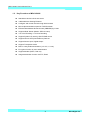
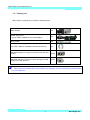
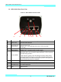
MDC-i4260C User’s Manual Part 1 MDC-i4260C User’s Manual Part 1 (Product Overview) MicroDigital Inc. www.microdigital.co.kr 1 MicroDigital Inc. MDC-i4260C User’s Manual Part 1 Contents 1. 2. Product Overview ...................................................................................................................... 3 1.1. MicroDigital® ..................................................................................................................... 3 1.2. MDC-i4260C ...................................................................................................................... 3 1.3. Key Functions of MDC-i4260C .......................................................................................... 4 1.4. Technical Specification of MDC-i4260C ............................................................................ 5 1.5. Packing List ....................................................................................................................... 7 Hardware Description ................................................................................................................ 8 2.1. MDC-i4260C Front Panel View .......................................................................................... 8 2.2. MDC-i4260C Rear Panel View .......................................................................................... 9 2.2.1. 3. CTL Port Description ................................................................................................ 10 MDC-i4260C HW installation and basic setup ........................................................................ 11 3.1. Before installation ............................................................................................................ 11 3.2. Factory Default Condition ................................................................................................ 11 3.3. MDC-i4260C Hardware Installation ................................................................................. 11 2 MicroDigital Inc. MDC-i4260C User’s Manual Part 1 1. Product Overview 1.1. MicroDigital® MicroDigital® is a device which digitizes analog Video from CCD Camera as digital stream and transmits over Internet. Users can monitor Video at any places in real time by MS Internet Explorer or Netscape Communicator without any additional software, if Internet access is possible. 1.2. MDC-i4260C MicroDigital® MDC-i4260C is a stand-alone device transmitting Video from built-in Analog Camera over IP(Internet Protocol) Network. It can transmit up to 30fps over the existing network such as LAN, leased line, DSL and Cable modem. You can monitor Video of MDC-i4260C through either web browser(MS IE or Netscape Communicator), if MDC-i4260C is connected to Network. MDC-i4260C supports Video compression both Motion-JPEG and H.264 simultaneously so that user can choose appropriate Video compression for the purpose. MDC-i4260C supports NTSC/PAL and 5 different size and 6 levels of Video quality. Picture 1 : MDC-i4260C 3 MicroDigital Inc. MDC-i4260C User’s Manual Part 1 1.3. Key Functions of MDC-i4260C Standalone device built-in web server 10M/100M Auto Sensing Ethernet Configure and control device through Web browser Max 30 fps transmission speed on TCP/IP network Effective Bandwidth & Bit-rate Control (VBR/CBR) by H.264 Supports Dual Stream (Motion JPEG & H.264) 1ch Voice Encoding / 1ch Voice Decoding Support Dynamic IP users by IPCCTVDNS server Support Various PTZ (Pan/Tilt/Zoom) Devices Support Sensor Input, Digital Output Support Transparent mode Built-in 2 way Audio transmission (1ch A-in, 1 A-out) Encryption function by user authentication Support Modem (Dial-in, Dial-out) Image transmission function via FTP, Email 4 MicroDigital Inc. MDC-i4260C User’s Manual Part 1 1.4. Technical Specification of MDC-i4260C Model Name MDC-i4260C Hardware 32bit Embedded CPU Flash 8Mbytes /SDRAM: 128Mbytes Linux version 2. 6.xx operating system Battery backed up real-time clock Image sensor 1.3M Micron Progressive CMOS Lens Minimum illumination Megapixel mount Video compression Motion JPEG H.264 Max Video Resolution 1280(H) X1024(V) 2.0 Lux Alarm I/O Interface Audio Support Audio Comression Audio In / Out 1280 X 1024 / 15 Frame per second 640 X 480 / 30 Frame per second Motion JPEG and H.264 Dual Streaming (Simultaneously) Controllable frame rate and bandwidth Compression levels: 6 (Motion JPEG) / 6 (H.264) Color: color, black & white APCM 4bit IMA Sampling rates 8KHz Audio 1ch in & 1ch out 10/100BaseT Ethernet auto sensing IEEE 802.11g Built-in wireless(Option) 1 Photo-coupled inputs and 1 Relay output 2way 8Bit PCM, 8Khz, 8Kbyte / Sec 1 In / 1 Out Power Over Ethernet Option Max Streaming Speed Video Streaming Image setting Voice LAN interface Serial Interface Security features Advanced Service Built-in Motion detections Others Management One serial port for console, modem(PSTN & GSM), serial input/output device, PTZ CTL Port is RS-232, RS-485 Max Baudrate: 115200 bit/s Multi user level protection for camera access, PTZ, Alarm I/O Up to 15.5M memory for Pre/Post alarm buffer e-mail, FTP, alarm Buffer by event or schedule IP notification, Alarm Notification to e-mail, CGI Call by event or schedule Accuracy: 12x12=144 blocks Motion Sensitivity : -100 ~ 100 : 100 is hypersensitive Transmit Serial input data transfer with Video IP notification by e-mail Configurable by serial, web or telnet Remote system update via telnet, FTP OR web browser. 5 MicroDigital Inc. MDC-i4260C User’s Manual Part 1 PWR Supply SMPS input: 100~240VAC, 300mA Output: DC 12 Volt, 800mA PWR Consumption DC 12Volt 500 mA Operating Environment Temperature : 41° ~ 122°F (5° ~ 50°C) Humidity : 20 ~ 80% RH(non-condensing) Users 16 simultaneous users Installation, management and maintenance Installation CD and web-based configuration Firmware upgrades over HTTP or FTP , firmware available at www.microdigital.co.kr Video access from Web browser Video access from Web browser Minimum Web browsing requirements System integration support Supported protocols Applications Pentium III CPU 500 MHz or higher Windows XP, 2000, NT4.0*, Internet Explorer 6.x or later Powerful API for software integration available at http://www.microdigital.co.kr, including Simple Viewer API, MicroDigital Control SDK, event trigger data in video stream, embedded scripting and access to serial port peripherals over HTTP/TCP User can be installed user program daemon for event notification or sending image. Embedded operating system: Linux 2.6 HTTP, TCP/IP, FTP, Telnet, RARP, PPP, PAP, CHAP, DHCP, SMTP client(e- mail), NTP, RTP/RTSP MicroDigital CMS, MicroDigital Software NVR(MDR-IS004) Table 1 : MDC-i4260C Specification 6 MicroDigital Inc. MDC-i4260C User’s Manual Part 1 1.5. Packing List MDC-i4260C’s packing box includes the following items MDC-i4260C 1ea Power Supply Unit (Power Cable & SMPS DC12V 0.8A Adapter) 1ea Direct Cable 1ea CD (User’s Manual, installation wizard and Pictures) 1ea MD-PWE Adapter (To supply to power through the LAN Cable.) Option MD-POE Adapter (To supply to power through the LAN Cable From POE Router.) Option Table 2 : MDC-i4260C Packing List Please check all the listed items are included in your package. For any missing items, please contact your local distributor. 7 MicroDigital Inc. MDC-i4260C User’s Manual Part 1 2. Hardware Description 2.1. MDC-i4260C Front Panel View Picture 2 : MDC-i4260C Front Panel B A Name Description A LENS MOUNT RING Adjustable hand-screw ring for LENS mount C-MOUNT LENS, Only with Lens option separately sold. (IRIS LENS can be mounted) Table 3 : MDC-i4260C Front Panel Description B LENS 8 MicroDigital Inc. MDC-i4260C User’s Manual Part 1 2.2. MDC-i4260C Rear Panel View Picture 3 : MDC-i4260C Rear Panel View A B C D E Name F G H Description A Power Conn. 12V DC Power Input port B LAN(Tx/Rx) LED (RED/GREEN) C POWER LED (RED/GREEN) D Factory Default E MIC Conn. 1ch Audio Input Port F CTL Conn. CTL Port (RS-485, RS-232, DI, DO) G SPEAKER Conn. 1ch Audio Output Port H LAN LAN Connector RED LED – LAN TX/RX(Light blinks when there is data transmission at the connected LAN. GREEN LED – LAN LINK(Light blinks when LAN is physically connected.) RED LED - Light blinks when power is provided.) GREEN LED – Light blinks when IP setup is done. This button can reset the factory default settings at the system. Especially when a user lost his/her admin-password, or when it got any uncertain faulty operation. - After reboot the system, wait until hearing two times of beep sound. - Keep pressing FD button for 5~10 seconds until hearing three times short beep sound. ACT LED blinks during the process. The system will reboot automatically when it’s completed. Table 4 : MDC-i4260C Rear panel Description 9 MicroDigital Inc. MDC-i4260C User’s Manual Part 1 2.2.1. CTL Port Description The following is Pin-out information of CTL Port to connect PTZ or Sensor (DI/DO). Pin number starts from the left. For RS-232 connection for Serial input device, Modem or Console (Hyperterminal.connection), RXD,TXD and GND are used. For connection to PC, RXD and TXD are used. RXD and TXD should be cross to communicate properly Picture 4 : CTL Port Description 10 MicroDigital Inc. MDC-i4260C User’s Manual Part 1 3. MDC-i4260C HW installation and basic setup 3.1. Before installation Read carefully User’s Manual Check User’s Network (IP Address, Network Mask and default gateway) Secure IP address for MDC-i4260C 3.2. Factory Default Condition The following table shows the factory default condition. Please refer to this when you need to change the values on admin menu. Factory Default Condition Admin ID root Admin password root IP address 10.20.30.40 Network mask 255.255.255.0 Gateway 10.20.30.1 Wireless LAN (Option) Disabled Table 5 : Factory Default Condition Factory default Admin ID and Password are all lower case letters. You can change the password with Capital letters. 3.3. MDC-i4260C Hardware Installation Following steps are the physical installation process for MDC-i4260C. 1. Connect cable to LAN port of MDC-i4260C. 2. Connect power cable and turn on power of MDC-i4260C (Await until booting is finished) 11 MicroDigital Inc. MDC-i4260C User’s Manual Part 1 After that, you need to follow the steps below. First, Network Configuration by MD-installer. Second, Camera Configuration by MD-installer or admin-menu. Third, Service Configuration by MD-installer or admin-menu. You can configure most settings on Admin menu by Web Browser so you have to configure Network first. 12 MicroDigital Inc.