1
ARUN MICROELECTRONICS LTD.
PRESSURE GAUGE CONTROLLER MODEL PGC1.
USER MANUAL ISSUE 1.31
For use with Program Version 2.00 onward.
COPYRIGHT RESERVED 1989
The information contained in this manual has been carefully checked and is believed to be correct. No
responsibility is assumed for any errors. User comment and criticism is welcome: please write quoting
the serial number of the instrument and the version number of the software as displayed by the
instrument to:
Customer Services,
Arun Microelectronics Ltd.,
Fitzalan Road,
ARUNDEL,
West Sussex. BN18 9JP.
England.
Please direct other enquiries to the distributor or agent from whom you purchased the instrument.
1
INDEX
1. INTRODUCTION
2. INSTALLATION
2:1 Checks on receipt of the instrument.
2:2 Ion gaugehead installation.
2:3 Instrument installation.
2:3.1 Mounting.
2:3.2 Ventilation.
2:3.3 Connection to the mains supply.
2:4 Fusing.
2:4.1 The mains fuse.
2:4.2 The grid fuse.
2:5 Ion Gauge Cables.
2:5.1 The ion gauge power cable.
2:5.2 The ion gauge collector cable.
3. OPERATION
3:1 Familiarisation
3:1.1 Power on, the LCD, switch functions and "HELP"
3:1.2 The SETUP menu. The security code and numeric data entry.
3:1.3 Exploring the menus.
3:1.4 Preparing to measure pressure. Setting the Ion Gauge
parameters.
3:2 Pressure Measurement.
3:2.1 Pressure measurement using Pirani Gauges.
3:2.2 Starting the Ion Gauge.
3:2.3 Problems with starting or running the Ion Gauge.
3:2.4 Measuring pressure with the ion gauge.
3:3 Operation at extreme UHV and emission current selection.
3:4 Operation of the ion gauge at high pressures
3:5 Process Control and Trips
3:5.1 Use and wiring of the relays.
3:5.2 Assigning the relays to gauges or functions.
3:5.3 Ion gauge trips.
3:5.4 Setting trip pressures before operating the ion gauge.
3:5.5 Setting trip pressures while operating the ion gauge.
3:6 Leak Detection.
3:7 Ion Bombardment Degas.
3:7.1 Degas programs.
3:7.2 Running degas.
2
3:7.3 Problems in degas.
INDEX
3:8 Bakeout Control
3.9 Capacitance Manometer
3:10 Recorder Output.
3:11 External inhibit of the Ion Gauge.
3:12 Remote operation
4. FAULTS AND WARNINGS
APPENDIX A Gauge principles.
A.1 Ionisation gauges.
A.2 Pirani Gauges
A.3 Capacitance Manometers.
APPENDIX B Connectors.
B.1 Mains connector.
B.2 Ion gauge power connector.
B.3 Ion gauge collector connector.
B.4 Pirani connectors
B.5 Bakeout thermocouple connector and cables.
B.6 Remote connector.
B.8 Auxiliary connector.
3
1. INTRODUCTION
This intelligent Pressure Gauge Controller is designed to replace earlier generation equipment and
provides enhanced performance and facilities at significantly reduced size and with no increase in cost.
The large easily- read LED display allows viewing of pressure in either bargraph or numeric formats,
selectable with a single keypress. A continuous voltage analog of pressure is available. Four
mains-power-rated changeover relays assignable to any gauge or function are provided.
Ease of Use
The instrument may be configured or set up by selection from menus displayed on a 24-character 2-line
liquid crystal display and such setups are maintained in the instrument's memory, even in the absence of
mains power. Information of secondary importance and extensive operator assistance in the form of
"help" screens are also available on this display in unambiguous plain English. An experienced operator
should be able to use the full facilities without referring to the Manual. After setup, certain functions may
be "locked out" to prevent unauthorised operation.
High Accuracy
The two most significant factors which determine the performance of ion gauge controllers are the
accuracy of emission control and the quality of the electrometer measuring the collector current. This
unit offers improvements in both of these critical areas.
Precise Emission Control
The filament power is provided by a smooth direct current supply controlled by a fast-acting control
circuit instead of the normal transformed and chopped mains supply. This allows control of emission
current to an accuracy of about 1%, besides eliminating a source of potential electromagnetic
interference. Emission current may be selected manually but, to allow optimal extension of the dynamic
range at extreme UHV, "Autoemission" modulates the electron current in a smoothly varying fashion to
maintain a usable collector current without creating a pressure burst from increased filament
temperature.
Advanced Electrometer Design
An electrometer with a logarithmic characteristic is included as this gives a wide dynamic range which is
guaranteed to be monotonic and smooth over the entire range of the ion gauge. A novel compensation
technique ensures that the error currents in the logging circuits do not cause an optimistically low
pressure reading to be given at the bottom of the operating range, as is common in log electrometers.
The settling time at low input currents is minimised by a new non-linear frequency compensation
technique. Conformance and high ambient temperature performance are improved by advanced
temperature compensation techniques. The electrometer is mounted directly in the path of incoming
forced air and is thermally isolated from internal sources of heat.
4
2. INSTALLATION
2:1 Checks on receipt of the instrument.
On receipt of the instrument remove all packing material and check that all items on the shipping list
have been received. Report any damage or shortages to the Company or the Agent who supplied the
instrument. The packing material has been specially designed to protect the instrument and should be
retained for possible future use.
2:2 Ion gaugehead installation.
Consult the information supplied with the gaugehead for advice on flanges, gaskets and adaptors for
mechanical fixing. Consult section 2:5 and Appendix B for more information on making or adapting
cables to connect between the gaugehead and instrument.
Mount the gaugehead in a position where the free electrons generated in its vicinity will not affect other
equipment. The performance of the ion gauge may be affected by other electron or ion generating
processes within the vacuum chamber: should shielding of the gaugehead be necessary, ensure that
the conductance between the gaugehead and volume of interest is not significantly decreased by its
presence. The orientation of the gaugehead should be such that the filament is to the side of, or below,
the grid structure. This will ensure that if the filament should sag or break it will not short-circuit to the
grid.
The gauge and controller are protected from all normal failure modes of either. Users should be aware of
potential hazards from other equipment, however, particularly those introducing high voltages into the
vacuum chamber (X-ray sources for example). As a direct discharge from one of these at high
pressure may cause extensive damage, shielding should always be introduced in such cases.
2:3 Instrument installation.
2:3.1 Mounting.
The instrument is suitable for mounting in a standard 19" rack and occupies 1U ( 1.75" , 44.5mm ) of the
rack. The mounting holes in the front panel are intended for retaining the instrument in the rack and will
not support its weight. Additional support is required toward the rear and various arrangements are
provided by rack manufacturers for this purpose. Support brackets may be mounted on the tapped M3
fixing holes on the sides near the rear. If these or other arrangements are attached to these holes,
ensure that the screws used are steel and penetrate the case between 6 and 10 millimetres.
2:3.2 Ventilation.
The instrument is forced-air ventilated through grilles on the right side and a vent in the rear panel.
Mount it in a location where there is an adequate supply of air as close as possible to cool room-ambient
temperature. The instrument is tolerant of, and is compensated for, operation at elevated ambient
temperatures and will give a warning when these are likely to affect measurements or safe operation. If
the temperature of the incoming air is measured at 45 Celsius or greater the instrument is placed in a
low-power mode of operation and a recommendation to switch off is given. Long-term accuracy and
reliability will be enhanced by operation at the lowest possible temperature. If there are other instruments
in the rack which generate significant amounts of waste heat, try to ensure that this is deflected away
from this instrument.
2:3.3 Connection to the mains supply.
The mains is connected via an IEC CE22 pattern connector.
THE INSTRUMENT MUST ALSO BE CONNECTED TO EARTH BY THE STUD PROVIDED. FAILURE
TO PROVIDE THIS CONNECTION MAY RESULT IN A SHOCK HAZARD FOR THE OPERATOR IF
HIGH VOLTAGES ARE CONNECTED TO THE GAUGE OR SIGNAL LEADS WHEN THE MAINS
5
LEAD IS DISCONNECTED.
The mains supply is filtered to prevent conducted electromagnetic interference affecting the operation of
this or other equipment nearby. To ensure that this filtering is effective, and because there is an earth
leakage current generated within the instrument, it is necessary to return this directly to the vacuum
system ground reference star point. Ensure that other instruments are directly and separately earthed so
that return or fault currents cannot flow in any common ground impedance. This is particularly important
in cases where there are high voltage power supplies in the system; there must be specific low
impedance paths for return or flashover currents, reliance on frame continuity or sneak paths will cause
noises and spikes to be coupled into instrumentation. Low resistance connections do not necessarily
have low impedance, which is most successfully achieved with a Litz conductor of large cross-section
and number of strands.
Information on wiring for process control will be found in section 3:5, below.
2:4 Fusing.
Two fuses for instrument protection are provided. Spare fuses are provided in the accessory kit. Do not
use fuses of other types or ratings, as this may result in damage to the instrument or gaugeheads under
fault conditions.
2:4.1 The mains fuse.
The rating of the mains fuse is dependent on the range of supply voltages from which the instrument is
to be operated, and is printed on the rear panel adjacent to the fuseholder. It must be replaced with a
20mm x 5mm anti-surge fuse of the same rating. Such fuses are marked with a "T" after the current
rating. There is provision to house a spare fuse in the fuse drawer, which is integral to the mains
connector. It is necessary to disconnect the mains supply when replacing fuses.
2:4.2 The grid fuse.
The grid fuse protects the instrument and ion gaugehead against short-circuits in the gaugehead during
electron bombardment degassing. It is a 20mmx5mm 125mA fast-acting fuse. This fuse is mounted
inside the instrument; to replace it disconnect the power connector and remove the smaller screws at the
sides of the instrument. Note that the ventilation slots are at the right side, when viewed from the front.
Remove the cover and locate the fuseholder on the right hand edge of the left hand circuit board. The
fuse is beneath a clear plastic cover and the rating is printed adjacent on the surface of the circuit board.
Replace the fuse and its cover. Replace the instrument cover and screws in the correct locations. Do not
use screws longer than those supplied.
2:5 Ion Gauge Cables.
The use of correctly constructed cables will enable the instrument to meet its specification. The following
is a general guide to the considerations affecting ion gauge cable construction: a specification of
connector types and pin connections is given in Appendix B.
2:5.1 The ion gauge power cable.
The ion gauge power cable must be made with conductors of cross section adequate to carry the
filament current at the highest ambient temperature expected. The cross sectional area of the wiring
should be a minimum 1 square millimetre. The grid wire carries a very small current, and its cross
sectional area is relatively unimportant. The insulation on all wiring should be rated for at least 1000 volts
RMS and should be adequately protected against mechanical damage.
A further consideration is the voltage drop in the cable at maximum filament current. This is again a
function of the gauge filament operating voltage and current, and is not well defined as it changes as the
6
filament ages. As a general guide a VIG17 or VIG22 gauge with tungsten filaments requires about 7
volts at just over 4 amperes during ion bombardment degas. This may increase up to about 10 volts at
the end of the filament's life. Iridium filaments require about half the voltage and current.
The total drop in the filament and cable which the instrument will accommodate is about 13.5 volts.
Voltages over this threshold will cause the instrument to report a filament or wiring fault. It is good
practice to minimise the drop in the cables by making them as short and of as large a cross section as is
convenient, as this minimises the temperature rise in the instrument.
2:5.2 The ion gauge collector cable.
The ion gauge collector cable should also be as short as convenient. Although this cable is screened,
the amount of interference which can be induced is proportional to its length and can become significant
at extreme UHV. Site the cable run away from other cables carrying high power or high frequency
signals. The cable installation should be such that movement or flexing is discouraged. Mechanical
movement of the cable can generate triboelectric charges which may affect UHV measurements.
It is important to avoid the production of "earth loops" in sensitive signal return paths as these can have
significant currents induced in them at mains frequency. The screen of the collector cable should ONLY
be earthed at the instrument end. If existing cables are to be adapted, and are currently connected to
earth at the gauge end, disconnect the screen but ensure that the guard cylinder around the collector
feedthrough on the ceramic gauge base remains connected to earth. This is important, as it provides a
path to earth for leakage on the surfaces of the ceramic from the grid voltage which would otherwise add
to the collector current.
3. OPERATION
The number of ways this instrument can be used is very large, but the underlying structure to the control
of its operation is very simple and consistent. The instrument will offer helpful prompts and explanation if
the "HELP" switch is depressed. For these reasons, this section of the manual is written in "tutorial"
style. Following the procedure below will ensure that the instrument is exercised in a way which will
result in the user learning in a logical sequence which will not result in damage to the instrument or
gaugeheads. As you progress the amount of detail given is reduced to avoid tedium: you should
therefore not skip sections, and only progress to the next when you understand the current one.
3:1 Familiarisation
Operation of the instrument is designed to be easy for users familiar with vacuum system operation and
with the types of gauges used. Brief descriptions of the principles of operation of various types of gauge
will be found in appendix A.
3:1.1 Power on, the LCD, switch functions and "HELP"
Connect the instrument to the mains supply. Do not connect any gauges or other equipment to the
connectors on the rear panel at this stage. Switch on. The liquid - crystal display (LCD) will show a short
sequence of messages and then wait for a response.
*****************************************************************
*
WARNING
*
*
*
* IT IS RECOMMENDED THAT YOU READ THE NEXT SECTIONS AS YOU *
*
MAY OTHERWISE INADVERTENTLY CHANGE CONTROL
*
* PARAMETERS WHICH WILL BE STORED IN THE INSTRUMENT'S
*
*
MEMORY, EVEN WHEN THE POWER IS DISCONNECTED.
*
*
*
*
DO NOT CHANGE THE SECURITY CODE WITHOUT
*
*
RECORDING THE NEW CODE.
*
*
*
7
*****************************************************************
There are four switches adjacent to the LCD, and those to which the instrument will respond at any time
show a green light. Those marked "INC" and "DEC" are used mainly to define choices from a menu, or
to change numbers displayed on the LCD. After making the changes they are confirmed by pressing the
"ENTER" switch: this usually produces a new display on the LCD. The "HELP" switch calls up an
advisory message on the LCD and sometimes there is a related sequence of these. In these cases the
last character displayed is an arrow and the next part of the sequence is called by pressing "HELP". The
LCD reverts to displaying the current menu after the last help message. All displays of "help" messages
are transient, and will change to the next in sequence or be replaced by the previously displayed menu
after a few seconds.
If you have pressed any switches, recall the initial menu by switching the power off for a few seconds.
You are asked to select from "RUN SETUP REMOTE". Press the "HELP" key to show an explanation of
these terms. When the "RUN SETUP REMOTE" menu returns press "INC" a few times and observe the
effect on the cursor shown on the LCD, then do the same with DEC. Note that the cursor jumps between
the ends of the display. Leave the cursor under "SETUP" and press "ENTER".
3:1.2 The SETUP menu. The security code and numeric data entry.
Selection of "RUN" or "REMOTE" will result eventually in a "FAULT" message being displayed, because
of the absence of gauges or a host computer. Although this is not harmful it is more instructive to view
the menus under SETUP first. Successive selections from this menu allow definition of units of pressure,
ion gauge characteristics, degas program parameters, assignment of relays to gauges and functions,
interlocks, bakeout parameters and capacitance manometer range.
If you have followed the procedure above the LCD should be showing on its top line :
"Enter the security code"
and the bottom line will show a flashing arrow pointing to the number 200.
The default value of the security code is 200. Press "Enter". Another menu should appear. If the same
menu and security code is displayed then the code has been changed to another value. Since there are
500 possible codes you should ask previous users which value they changed it to. If this information is
not available, consult the Company or agent from whom you purchased the instrument to find out how to
restore the security code to 200. It will be necessary to quote the serial number and software version
number.
The top line of the display now shows:
"Change the security code"
and the lower line shows a cursor underlining "no". Press "Enter" to confirm that you do not wish to
change the security code from 200.
The next menu allows you to define the units of pressure measurement. This, and the next few
succeeding menus are not of immediate interest and can be skipped by pressing "Enter", which confirms
the previous or default selection. Continue to do so until the top line of the LCD display shows:
"ION GAUGE overpr. trip"
Note that the lower line shows the overpressure trip in scientific notation in the selected units of pressure
measurement. The default value is 1.0E-02 millibars. A flashing arrow is pointing toward the exponent
part of the display. This number can be changed by pressing either the "INC" or "DEC" switches. Note
that, if you keep the switch depressed, the number continues to change and that the rate of change
increases after a short while. When the allowed limit value has been reached the number stops
8
changing and the green light in the switch is extinguished. You must then press the other switch to
change the number in the opposite direction. Return the exponent to the default value and press the
"ENTER" switch. You are now asked to change the mantissa in exactly the same way. Note that the
mantissa overflows into the exponent at the end of each decade. This is the general procedure for entry
of all scientific-format numeric values into the instrument.
You should now progress to the end of the setup sequence of menus by pressing "ENTER" repeatedly
until "RUN SETUP REMOTE" is displayed. Alternatively, if you have become lost switch off for a few
seconds.
3:1.3 Exploring the menus.
By this time you will be able to progress through the menus and use the help messages with facility,
although you are advised not to change any parameters whose significance you do not fully understand.
Progress through the "RUN" and "REMOTE" menus (as far as possible without the presence of a host
computer or gauges) in order to become familiar with the structure of the control menus, help and error
messages.
If you become "lost" in the menus, you can escape either by switching off for a short period or by
selecting options such as "STOP" and "EXIT" when these are presented. Sometimes, you will have to
complete a sequence of selections which you have inadvertently entered. Pressing "ENTER" in any
menu without moving the cursor confirms the previously selected choice and is an easy, rapid way of
skipping through a long sequence of choices where no change is required.
For ease of use, the menus are arranged so that after swiching power on two presses on the "ENTER"
key will start pressure measurement with the ion gauge. Since completion of any sequence returns to
the "RUN SET REMOTE" menu, over - enthusiastic pressing of this switch will cause the gauge to start!
3:1.4 Preparing to measure pressure. Setting the Ion Gauge parameters.
Enter the "SETUP" menu. Set and record the required security code and the units of pressure
measurement.
The gauge sensitivity may be entered in units other than the units of pressure measurement: press
"INC" until those you desire are displayed and then press "ENTER". Adjust and enter the numeric value,
according to the gaugehead manufacturer's specification.
Select the filament type. This adjusts the limits on maximum allowed filament current and degas power
and alters the choices available in some subsequent menus. Selecting the incorrect type will cause
problems. Selection of "Iridium" for a tungsten filament gauge will probably result in insufficient power
being available, but selection of tungsten for an iridium filament gauge will probably destroy the filament
at some time. If you do not know the type of filaments in use select "Iridium", as this will give the greatest
protection to the gaugeheads, although it may not be possible to operate one which is actually tungsten
properly under all conditions.
You are now asked to adjust the filament current limit. If the gaugehead manufacturer has a
recommended limit adjust to a little below that limit. In the absence of a recommendation select about
1.5 Amps. for Iridium and 3.0 Amps for Tungsten. This will probably be too low for most gauges under all
conditions but will protect the filaments. Use an instrument screwdriver with a 3mm blade, and insert this
in the hole adjacent to the "HELP" switch on the front panel marked "ILIM". Using no more pressure than
is necessry to keep the screwdriver in the slot, turn the single-turn adjustment until the desired limit is
displayed on the LCD.
Adjust the Ion Gauge overpressure limit to the recommended value or lower. The default value of 1.0E02 is satisfactory for most gauges.
Skip through the menus till:
9
"Pirani 1 interlock - "
appears and set it as desired. Skip through the remaining menus. You are now ready to connect gauges
and measure pressure.
3:2 Pressure Measurement.
Before connecting the instrument to any gauges you should perform the suggested familiarisation
procedure described above. As an absolute minimum you must have completed the procedure in
section 3:1.4, as failure to do so may result in destruction of the Ion Gaugehead.
3:2.1 Pressure measurement using Pirani Gauges.
Switch off, disconnect the mains power lead and connect the gauges. It is assumed that Pirani 1 is
protecting the ion gauge; ensure that the correct lead is connected to the Pirani 1 connector on the rear
panel.
Reconnect the power lead, and switch on. Pirani gauges and capacitance manometer are powered up
immediately. The left section of the LED display shows a histogram of Pirani pressure at all times. This
should be read against the scale at the top or bottom as indicated by the line to the illuminated pressure
unit indicator LEDs at the left end of the main section of the LED display.
Pressing the "DISP" switch will change the format of the display and the source of the measurement
sequentially. P1 and P2 are Pirani gauges and C is the capacitance manometer.
Pirani gauges are not very accurate or repeatable transducers at pressures close to atmospheric. For
this reason, the instrument has no discrimination of pressures between 1 bar and 5 mbar. This is of no
practical consequence, since a typical rotary-pump roughed system will traverse this range in a few
seconds and will adequately indicate that pumpdown is progressing by making the characteristic noises.
Badly-calibrated or oil-contaminated Pirani gaugeheads may even indicate 5 mbar or less at
atmospheric pressure! Accurate pressure readings in this range are achieved by capacitance
manometers. If the Pirani filament should fail, the circuit is arranged to give a reading of 1 bar.
3:2.2 Starting the Ion Gauge.
Start pumping the system. When the system pressure is low enough, attempt to start ion gauge
emission by selecting "St" on the menu. The Pirani interlock will prevent this if Pirani 1 pressure
indication is above 1x10E-2 millibars. Pirani gauges are generally more repeatable at the lower end of
their pressure range, although not necessarily more accurate. There is sometimes an adjustment for the
low pressure end of the scale, and this may need attention. Alternatively, if you are confident that the
system pressure is low enough and the Pirani interlock is preventing the ion gauge from being run, then
enter the "SETUP" menu and switch off the interlock.
If you have succesfully started the ion gauge refer next to section 3:2.4.
3:2.3 Problems with starting or running the Ion Gauge.
If " FAULT IG underemission trip" is reported at startup or on increasing emission this is probably due to
the filament current limit being set too low. However, if the grid is not connected or shorted to ground the
same message will be given. Prudent operators will check the cables before increasing the allowed
filament current. Disconnect the mains power connector before checking any cables. The filament
current limit adjustment can be made at any time but in order to view the limit you must enter the
"SETUP" menu, as described in section 3:1.4.
10
If "FAULT IG overemission" is shown there is probably a short circuit from grid to filament. Disconnect
the mains power connector before checking any cables.
If "Fault IG filament open circuit" is shown the cable or filament is probably open circuit. Disconnect the
mains power connector before checking any cables. In some cases if there is a high resistance
connection or the cable is long or of inadequate cross section this fault may be reported after some
period of normal operation. To change to the other filament return to the initial menu under "RUN" and
select "Other" and then "Fil".
3:2.4 Measuring pressure with the ion gauge.
Emission is initiated at 0.1mA. Review the formats of pressure display available by pressing the "DISP"
switch and then increase the emission current to 1mA and then 10mA by the appropriate selection from
the menu.
This may have caused "Fault IG underemission trip" to be reported. In this case the filament current limit
may be set too low to support the increased emission. The filament current limit adjustment can be
made at any time but in order to view the limit you must exit the "RUN" menus and enter the "SETUP"
menu, as described in section 3:1.4.
When you have achieved 10mA emission you should then turn the "ILIM" adjustment slowly
anti-clockwise just until underemission is reported. View the limit in the "SETUP" menu and then
increase it slightly to give a margin of safety. The setting may also need to be adjusted if the gauge
requires more power during ion-bombardment degas at relatively high powers. If the ion gauge or
filament is changed the adjustment will need to be repeated. It is worthwhile taking the trouble to find the
optimum setting of this control, as this will improve the protection and longevity of the filament.
Ion gauge operation may also be initiated by selecting Au (autostart) from the first menu displayed after
selection of "RUN". This starts the ion gauge during pumpdown when Pirani 1 pressure indicates less
than 1x10E-2 millibars. The autostart function is allowed to function only once after selection, and the
gauge will not be restarted if the ion gauge overpressure trip is subsequently temporarily exceeded. The
overpressure trip is independent of the Pirani interlock pressure.
During emission the Pirani pressure is indicated in numeric format on the top line of the LCD. The status
of the four relays is shown to the right of "Relays" on the bottom line. Four digits represent relays A, B, C
and D from left to right. "0" represents the de-energised condition and "1" represents the energised
condition. The entire display can be replaced by a display of the status and trip pressures of the relays,
which may then be changed, by selection of "Relays". More information on this is contained in section
3:5, below. Selection of "Q" (quit) will restore the former display.
3:3 Operation at extreme UHV and emission current selection.
You may select 0.1, 1 or 10mA of emission current in the ion gauge, as the gauge is being operated, or
allow the instrument to adjust to the optimum current by selecting "AUTO". For the vast majority of
measurements emission of 1mA will be used. Although most gauges are substantially linear and the
instrument regulates emission current well, maintaining 1mA emission wherever possible will eliminate
some error in the readings. 10mA emission is used at the extremes of UHV and the instrument will
advise when this is desirable (because the limits of the dynamic range of the electrometer at its current
ambient temperature are being approached.).
If there is some fluctuation of the ion gauge pressure readings at very low pressures, these may be
reduced by increasing the time-constant of the filter. To do this, "STOP" the ion gauge, select "Other"
then "FIL". Select a time which just exceeds any observed periodicity in the fluctuations, or the minimum
time which reduces them to an acceptable level. The trips and trend indicator operate on unfiltered
pressure readings, so their response times are not affected by the filter.
11
Automatic control of emission current ensures that the dynamic range of the ion gauge is extended at
low pressures without manual intervention. The emission current is progressively increased as the
collector current decreases. This is done in small increments, to avoid pressure bursts caused by
increased evolution of adsorbed gas at the higher filament temperature necessary to support the
increased emission. If the gauge requires degassing, or if the photocurrent in the collector generated by
soft X-rays from the grid is large compared to the ion current, the instrument detects this and
recommends a return to manual selection of emission.
This instrument contains an advanced electrometer circuit which is well compensated for environmental
changes. It is located directly in the path of a cooling airflow just where this enters the instrument, and it
is thermally isolated from sources of heat. Its ambient temperature is monitored, and if this approaches a
level at which pressure readings may be degraded, an advisory warning is given (stating the measured
temperature). This will occur only at extreme UHV and very hot ambient temperatures. Increasing the
emission current to 10mA will improve the accuracy of the readings. If warnings are regularly given with
10mA emission, you are advised to improve the cooling arrangements to improve the life and reliability
of the instrument.
Operation of the instrument in conditions of high humidity may affect extreme UHV measurements if
condensation is allowed to form within the case. The most common cause of this is introducing a cold
instrument into warm conditions. If this situation exists it will normally be self-correcting after a few hours
of operation in non-condensing conditions.
3:4 Operation of the ion gauge at high pressures
For operation at the upper end of the ion gauge pressure range, an emission current of 0.1mA is
available. This should not be used as a means of extending the upper limit of operation as the filament
temperature is only slightly reduced, and oxidation (and other) reactions are not significantly retarded.
Iridium filaments are more suitable for relatively high pressure measurements with Ion Gauges.
3:5 Process Control and Trips
Four process control relays are provided, which can be used in many ways. The relays and their
contacts are described in the following paragraph, and their assignment and use in the remainder of this
section.
3:5.1 Use and wiring of the relays.
The contacts of the relays are shown diagramatically on the rear panel legend, in the de-energised
condition, adjacent to the terminal blocks to which they are connected. Switching loads of more than 5
Amps is not recommended. Bakeout heaters will require an external contactor for switching. Inductive
loads, including contactor coils, should have "snubber" networks connected in parallel to avoid arc
generation which could interfere with the operation of this and other equipment. In general, avoid
introducing noise sources into the instrument via the relay contacts.
The external wiring is connected to the instrument through a two-part pluggable terminal block. This can
be removed and wired independently of the instrument. Ensure that external wiring is of adequate cross
section for the load current. Strip and twist the wires (do not tin them) and poke into the receptacle in the
terminal block. Close the leaf on the wire by tightening the screw immediately above. Take appropriate
action to strain-relieve the wiring nearby and to restrict access to the terminals if harmful
voltages are to be present.
3:5.2 Assigning the relays to gauges or functions.
Switch on the instrument or return to the initial menu and select "SETUP" of the configuration
12
parameters. Progress to the display which has "RELAY A" on the top line. The content of the bottom line
will depend on the options fitted to this particular instrument and defines the gauges or functions to
which the relay can be assigned. Selecting "OTHER" will reveal another set of possible assignments.
Selecting "OTHER" again may reveal more sets or return to the first set, according to the fitted options
and software. It is suggested that relay A be assiged to the Ion Gauge, in order to obtain the required
displays at later stages of this procedure. Assign relays B,C and D with reference to the following
paragraphs.
If a relay is assigned to a gauge, the relay is energised when the pressure is below the setpoint. The
hysteresis is fixed and the relay will de-energise when the pressure exceeds twice the setpoint pressure.
Adjustment of setpoints is described in section 3:5.3.
If a relay is assigned to TSP, that relay is energised momentarily to trigger a titanium sublimation pump
controller into renewal of the getter layer. The time between energisations is related to current pressure,
in accordance with the following table:
pressure exponent mBar
> -6
-7
-8
-9
-10
-11
delay time
infinite
10 min
30 min
90 min
10 hours
infinite
Refer to the manual of the TSP controller for information on how to use the momentary contact closure:
in some cases a voltage source is necessary.
A relay assigned to Bakeout is energised to switch on the bakeout heaters. More information on this is
contained in section 3.8, below.
Relays which are not assigned to a gauge or other function should be assigned to "None". These relays
may be energised or de-energised by the operator while measuring pressure and may be useful in
various ways.
3:5.3 Ion gauge trips.
After assigning the relays you are asked to specify what state the relays should be in when the ion
gauge is not operating. Normally, these relays are only energised when the pressure is below the trip
level. It may be useful, however, to specify "En" when the gauge is not operating, taking into account that
if more than one relay is assigned to the ion gauge that they will be all be affected.
After assigning the functions of the relays progress to the end of the "SETUP" procedure.
3:5.4 Setting trip pressures before operating the ion gauge.
Enter the "RUN" menu and select "Other" then "Rel". If you have followed the suggestion in section 3:5.2
the LCD display will show:
"Relay A IG EN DN"
on the top line. IG shows the assignment of relay A. Note that the cursor is positioned under IG.
Pressing "ENTER" confirms that the trip is to be active, whereas moving it to EN or DN and pressing
"ENTER" suspends the trip and energises or de-energises the relay, regardless of pressure. Whatever
choice is made you are then required to enter the trip pressure in the normal way.
You will find that only those relays which have been assigned to a gauge will appear in sequence
13
because there is no pressure setpoint associated with those which have been assigned to other
functions and it is not possible to suspend control of the relays.
3:5.5 Setting trip pressures while operating the ion gauge.
Start the ion gauge. Note that at the bottom right of the LCD display "Relays" followed by a four digit
number is shown. Press "HELP" for an explanation of this.
Move the cursor under relays and press "ENTER". The relays, their status and setpoints are then
displayed. The display will revert to the previous display after a few seconds. Before this happens move
the cursor and note that it moves between sections relating to individual relays. Press "ENTER" when
the cursor is on the relay of interest. The resulting display is exactly analogous to that decribed in section
3:5.4, above.
3:6 Leak Detection.
The leak detector works by indicating rapid changes of pressure on a bargraph and optional
frequency-modulated tone. Such changes are produced with a probe gas or volatile blocking agent. It is
difficult to exercise this function unless you have a leak valve (or a leak!) on the system, although you
may be able to produce a pressure burst by switching on other equipment or firing a titanium sublimation
pump. During leak detection the TSP program is prevented from triggering the TSP, but the ion gauge
overpressure trip and process control relays function normally.
Select "Lk" on the "RUN" menu and then select which gauge is to be used. This will depend on the
pressure at which the leak is limiting pumpdown. If you select the ion gauge the emission is set to 1mA
and the interlock with Pirani 1 still functions. The LED display now shows a histogram of rate of pressure
deviation with baseline restoration, and the LCD menu allows you to change its sensitivity (by selecting
"Gain") and to switch on the tone by selecting "Sound". If you have means to simulate a leak, you should
do so and observe the effect on the display and tone.
After a pressure change has been observed, turn off the probe gas supply or stop applying the blocking
agent and wait until the baseline restorer has caused the histogram and tone to return close to the
centre of their range. This shows that the leak detector has adjusted to the new system pressure and
does not necessarily indicate that the pressure is the same as before probe gas was introduced via the
leak. A blocking agent may give rise to a deviation first to the right and then to the left before settling. A
probe gas may give a single deviation in either direction, depending on the relative sensitivity of the ion
gauge to the residual gas in the chamber and the probe gas, and to the relative pumping rates for those
gases. If the deviation had been significantly greater than the maximum displayable on the LEDs you
should reduce the sensitivity. The lower gain should be used if significant random deviations unrelated to
probing are observed. Further localisation of a leak may be attempted after the deviation has been
restored.
3:7 Ion Bombardment Degas.
Ion gauges may be degassed by ion bombardment of the grid structure. The grid is biased to a nominal
+500 volts with respect to earth. The filament operates close to earth potential. Emission is regulated to
produce dissipations of up to 50 watts in the grid, in order to raise it to red heat.
3:7.1 Degas programs.
Preset programs for degas are available and these may be modified to suit gauge requirements in the
configuration parameters under "SETUP". Programs 1 and 2 allow a stepped increase in emission to be
applied, at minute intervals until the specified power is achieved, in order to reduce the pressure burst.
That power is then maintained for the rest of the degas period. Modification of the programs may be
necessary to suit the pumping capacity of the system and the condition of the gaugeheads. The "quick"
14
program allows the operator to apply degas power for one minute at the selected power. If a degas
power step of 2 watts per minute is selected, the first step will be 4 watts, because normal emission at
10mA gives a grid dissipation of 2 watts. A maximum degas power of only 30 watts is allowed for Iridium
filaments in order to avoid evaporating the Thoria coating.
3:7.2 Running degas.
Gauges should have been run for some time at 10mA emission before selecting "DEGAS". Ensure that
the pressure in the system is sufficiently low, and that the pumping capacity is adequate for the expected
gas load. Degas operation at high pressures may result in the production of glow discharges in the
gauge space, or oxidation, or other reactions at the surface of the gauge filament which will reduce its
life.
During degas the power and the remaining degas period are displayed on the LCD, together with "DEG"
on the LED display. The cursor is left in a position where one press on the "ENTER" switch will stop
emission.
Degassing the collector electrode is of little practical significance. However it can be achieved by making
up a special section of lead to connect the collector BNC connector into the grid connection on the ion
gauge socket. Appendix B contains details of these connectors. This lead section must be removed
after degas is complete.
3:7.3 Problems in degas.
If "FAULT IG underemission trip" is reported, the most likely cause is that the filament current limit is too
low because the gauge needs a higher filament temperature to support more emission current. Before
adjusting the limit check that normal emission still works.
If emission cannot be established the grid fuse is probably blown. Refer to section 2:4 for instruction on
how to replace this fuse. You should also check for a short circuit between the grid and filament and the
grid and chamber earth, as these are the most likely causes of excessive grid current. Another possible
cause of excessive current during degas is operation at high pressure; if this cause is suspected reduce
the degas power or its rate of increase in order to reduce the outgassing rate from the grid.
If "FAULT IG overemission" is reported, there was either a discharge caused by a high gas load, or a
short-circuit between grid and filament. If no short-circuit is found, check that emission at 1mA is
satisfactory. If this is so, check the grid fuse and attempt degas again at a lower power or lower power
step size.
3:8 Bakeout Control
The bakeout control function allows switching of heaters in accordance with system temperature
measured by a type K thermocouple, and pressure indicated by the ion gauge. Take care to connect the
thermocouple correctly. For further details on this refer to Appendix B.5. It will be necessary to use an
external relay or contactor to switch the heater current, as the rating of the internal relays is inadequate
for this purpose. An internal relay should be used to energise the coil of the contactor: as this presents
an inductive load a snubber should be fitted.
Progress through the "SETUP" configuration parameters, and assign a relay to the Bakeout function.
Continue until the Bakeout menu is reached. You are asked to confirm whether the preset program is
satisfactory, and you may change the total time (including warmup), the temperature setpoint and the
overpressure trip point. The operation of the ion gauge at the end of bakeout may be specified. Emission
of 10mA is recommended, as this runs the gauge hotter and discourages material from condensing on it
as the system cools. Continue on to the "RUN" menu and select Bk.
During bakeout the relay controlling the heaters is energised when the temperature is below the
15
setpoint, provided the overpressure trip is not exceeded. The hysteresis on temperature switching is 5
degrees Celsius, and that on pressure is half the trip pressure. The status of the heaters is shown on the
LCD, together with current temperature, pressure, and bakeout time remaining. The LED display shows
"BAKEOUT". The cursor is left in a position such that a single press on the "ENTER" switch stops
bakeout.
If the thermocouple is disconnected, reversed open-circuit, "FAULT" is shown on the LEDs and you are
asked to check and confirm it is satisfactory. If it was faulty the problem should be rectified, the cursor
moved to "OK" and "ENTER" pressed. If the fault cannot be rectified, moving the cursor to "Not OK" and
pressing "ENTER" aborts the bakeout.
An open circuit thermocouple gives a temperature close to 0 degrees. As it is possible that the chamber
is at this temperature or colder at the start of bakeout, the reading may be valid. In this case pressing
"ENTER" with the cursor on "OK" will allow the bakeout to run for 30 minutes, after which time a
temperature reading of below 5 degrees Celsius again gives a fault indication and stops bakeout.
3.9 Capacitance Manometer
The capacitance manometer (CM) is connected via the Auxiliary Connector. For details on this
connector refer to Appendix B.8. The instrument caters for unheated capacitance manometers with
full-scale output voltages of 10v, representing 10, 100 or 1000 millibars or Torr. 15v and -15v power is
available to drive the CM at up to 35mA, if your CM requires more power than this an external power
supply will be required: this will also allow heated CMs to be used. These have better resolution and
stability.
Ensure that the full-scale selected in the "SETUP" configuration parameters matches that of the CM.
Although this has to be set in millibars or torr, the readout is scaled in the selected display units. The CM
can be interrogated by pressing the "DISP" switch until the CM pressure reading appears. This is only
available in numeric format. If the pressure measured by the CM is greater than its fullscale, or if it is
disconnected, the reading is replaced on the LEDs by "CM > FS".
3:10 Recorder Output.
An analog voltage representing pressure is available on the auxiliary connector. This is scaled at +0.25
volts per decade of pressure and 0 volts represents 1.0x10E-14 in the selected units of measurement.
When the ion gauge is operating, its filtered pressure measurement is represented; otherwise that of
Pirani 1 is used as the source.
The output resistance of the recorder output is 1 kilohm and the output will withstand a continuous
short-circuit to either +15v, 0v or -15v, which are all present on the auxiliary connector. Consult appendix
B.8 for information on connector type and pin numbering.
If an analog voltage representing pressures above the ion gauge range is required when the ion gauge
is operating, the voltage output of the capacitance manometer is recommended. The output impedance
of this is generally such that a recorder may be driven directly.
3:11 External inhibit of the Ion Gauge.
Operation of the ion gauge may be inhibited by an external contact closure, which prevents starting of
the ion gauge by any means. The contacts should be connected to pins 7 and 8 of the Auxiliary
connector and must be isolated from any external source of voltage. Gold-plated contacts are
recommended as the internal voltage and current source are small.
16
3:12 Remote operation
Control and interrogation of the instrument by a host computer through the Remote connector is
possible. A demonstration program which will run on any IBM XT, AT or compatible computer is
available on diskette. The host computer must have at least one RS232 serial port. Up to eight
instruments may be connected to one serial port and each is identified by a number from
1 to 8 which must be selected when remote operation is initiated.
Information on the interface protocols is given in Appendix C, below.
All instruments connected to the serial interface should be switched on before "REMOTE" is selected on
any instrument. Do not switch off any instrument which may be communicating with the host computer.
The preferred method of disconnecting an instrument from an active interface is to exit "REMOTE" and
to disconnect the Remote connector, before switching it off.
4 FAULTS AND WARNINGS
All faults or potential faults detected by the instrument are announced on the LED display, and more
detailed information is shown on the LCD display. Normally, this gives the user the option to cancel the
message by pressing the "ENTER" switch which returns the LCD to the first menu under "START".
Before doing so it is normally worthwhile pressing the "HELP" switch, which will cause the LCD to
display further useful information regarding the fault. Once "ENTER" has been pressed this information
is no longer available.
Most of the messages likely to be shown in normal service have been described in the appropriate
section above. The remaining ones concern dangerous overtemperature conditions and fault diagnosis,
and are adequately amplified by "HELP" messages, where required.
Environments where there is a large amount of electrical noise may cause occasional erratic behaviour.
This will show as a blank or unintelligible LCD display or a spontaneous return to the RUN SETUP
REMOTE menu. In the former case pressing the HELP key will restore the display. The second
symptom shows that the instrument's program has been disturbed in some way. Normally, the stored
operating and setup parameters will not have been altered: if they were then a warning message will be
displayed. Operation may be restored in the normal way.
If this occurs more than extremely infrequently you should attempt to cure the problem at the source of
the noise. The most common cause is noise coupling via inadequate earthing arrangements. Refer to
section 2:3 for general advice on this point.
APPENDIX A
A.1 ionisation gauges.
Ionisation gauges are thermionic triode devices. The appropriate choice for UHV use is the
Bayard-Alpert type. This consists of a very thin collector wire mounted along the axis of a cylindrical
mesh grid. The filament is outside the grid and usually parallel to it. The grid is voltage-biased positively
with respect to the filament, and the collector negatively.
A stabilised emission current is established between the incandescent filament and the grid structure.
Electrons oscillate on long paths through the open grid structure, being repelled from the central
collector and attracted to the grid. A proportion of the electrons encounter gas molecules before
reaching the grid. These molecules are ionised by the collision and are attracted to the collector to form
a current, which is proportional to the concentration of gas molecules over a very wide range.
Pressure may be derived from the ion current by solving the equation:
17
Ion current
Pressure = -----------------------------Sensitivity x Emission Current
where the units for the two currents are the same and the sensitivity is a quoted constant for a particular
gaugehead and gas species.
The impact of electrons on the grid stucture generates soft X-rays; some of these impinge on the
collector and release photo-electrons. These form a small current in the same direction as the ion
current. When this 'photocurrent' becomes significant in relation to the 'true' ion current, the gauge
ceases to function as a reliable pressure transducer and is said to have reached its 'X-Ray limit'.
A.2 Pirani Gauges
The Pirani Gauge is a thermal conductivity gauge. A tungsten filament in the vacuum space is heated
from a constant voltage source and is incorporated in a Wheatstone bridge. The electrical resistance of
the filament depends on its temperature and this in turn depends on the rate at which heat is conducted
away from the filament by residual gas. The thermal conductivity of a gas depends on its pressure
(below about 1 millibar) and the nature of the residual gas. The Pirani gauge unbalances the
Wheatstone bridge and the voltage across the bridge represents pressure over the range of 0.5 millibar
to about 1x10E-3 millibar.
The lower pressure limit is determined by the heat loss due to radiation becoming significant compared
to that due to thermal conductivity. The radiant heat loss depends on the emissivity of the filament. A
new filament is bright, but can become blackened by deposits from decomposed rotary pump oils and
the lower limit of pressure readings will rise. It is possible to clean filaments.
A.3 Capacitance Manometers.
Capacitance manometers operate by measuring the deflection of a thin circular radially tensioned
membrane between the vacuum space and a reference volume at a pressure substantially below the
operating range of the transducer. The deflection is measured as a modulation of the electrical
capacitance between the membrane and a fixed plate and converted to a voltage proportional to the
pressure difference across the membrane.
18
APPENDIX B
Connectors
IN THE SECTIONS BELOW THE MATING CONNECTORS ON THE CABLES ARE DESCRIBED.
B.1 Mains connector.
This is a female IEC CEE22 type and is supplied with the instrument in the accessory pack in the form of
a moulded lead with integral 13 Amp. British domestic-style plug.
If you need to change to an alternative style of connector take care to make the connections correctly to
ensure operator safety. The wires are colour-coded as follows:Brown
Line
Blue
Green and yellow
Neutral
Earth
B.2 Ion gauge power connector.
This is supplied with the instrument in the accessory pack, in the form of a kit of parts. It is a 6 pin ITT
Cannon "Trident" rectangular male type. In the USA equivalent types are available from Burndy Inc.
ITT
Burndy
Cable mounting plug
229-23593J SMS 6 P-1
Hood
229-23597H SMS 6 H-1
Crimp pin (6 required)
229-90010L SM 16 ML-11S6
Pin connections are:
1
2
3
4
5
6
Safety interlock
Grid
Safety interlock
Filament common
Filament 1
Filament 2
Pins 1 and 3 must be connected together by a short wire within the housing. This forms part of a safety
interlock which prevents power being applied to the ion gauge connector when the gauge lead is not
mated.
Information on suitable cable construction and installation will be found in section 2:5, above. Suitable
crimp tools are available from ITT Cannon and Burndy and many other suppliers. The connector hood is
closed on the cable by a cable tie, which is supplied in the kit.
B.3 Ion gauge collector connector.
This is a 50 ohm BNC type free plug.
B.4 Pirani connectors
Two of these are supplied with the instrument in the accessory pack. They are 3 way DIN audio free
plugs with screen. Types with or without latches may be used.
Pin connections are:
1
2
Bridge supply 0v red
Signal voltage green
19
3
Bridge supply 2.06v yellow
The colours refer to those of the conductors in VG PVG1 leads. The blue wire is not used and the end
should be cut back and insulated. The pin numbering is consistent with that of the connector types
formerly used.
B.5 Bakeout thermocouple connector and cables.
This is a miniature flat pin K type connector, for example Labfacility type FMTC-K-M.
The thermocouple should be a type K insulated junction type and must be connected the correct way to
the plug. The brown wire should be connected to the terminal marked "+" and the blue wire to the
terminal marked "-". If a thermocouple with an uninsulated junction is used and allowed to touch any
conducting surface serious errors of temperature measurement will occur. CONNECTION TO ANY
SOURCE OF VOLTAGE MAY DAMAGE THE INSTRUMENT.
Mineral-insulated K thermocouples are recommended and are inexpensive and widely available. If the
lead supplied is not long enough extend it with type K extension wire and connectors only. Using copper
or other types of extension cables may give rise to serious errors of temperature measurement.
Signal voltages from thermocouples are very small so some precautions against induced interference
are desirable. Mineral-insulated thermocouples are well-screened but the installation should only earth
the screen at one point to avoid currents in the screen. Insulated thermocouple wires or extension
cables should be twisted together to avoid magnetic induction and routed away from power cables.
B.6 Remote connector.
This is a 25 way "D" type female connector. Used pin connections and signal names are:
3
2
5
Received data
Transmitted data
Signal ground
The signal levels on pins 2 and 3 are compatible with those of the RS232C standard. However, the
signals may be connected to up to eight of these instruments, which is not catered for in the standard.
B.8 Auxiliary connector.
External connections should be made to a free 8 pin DIN audio connector with screen, as supplied in the
accessory kit. Types with or without latches may be used.
Connections for the recorder output are:
1
Signal voltage
6
Signal return (earth)
Connections to the capacitance manometer are:
2
+15 volt supply
3
Signal voltage (i.e. manometer output)
4
Signal return and supply 0 volts
5
-15 volt supply
Connections to the remote inhibit lines are:
7
Not Inhibit
8
Signal return (logic ground )
20
21
ARUN MICROELECTRONICS LTD.
PRESSURE GAUGE CONTROLLER MODELS PGC1 and PGC1F.
INTERFACE MANUAL ISSUE 2
For use with Program Version 2.20 onward.
COPYRIGHT RESERVED 1998
The information contained in this manual has been carefully checked and is believed to
be correct. No responsibility is assumed for any errors. User comment and criticism is
welcome: please write quoting the serial number of the instrument and the version
number of the software as displayed by the instrument to:
Customer Services,
Arun Microelectronics Ltd.,
Fitzalan Road,
ARUNDEL,
West Sussex. BN18 9JS.
England.
Please direct other enquiries to the distributor or agent from whom you purchased the
instrument.
CONTENTS
1. INTRODUCTION.
2. HARDWARE.
2:1 PGC1 Line Drivers and receivers.
2:2
2:3 RS485/422 Line termination.
2:4 Cable construction and installation.
2:5 Host computer line drivers and receivers.
2:6 Demonstration software.
3. INTERFACE PROTOCOL.
3:1 General Command and Response formats.
3:1.1 Host Computer Commands.
3:1.2 PGC1 response.
3:1.3 Timing of Next Command.
3:2 PGC1 Response time.
3:3 Local/remote control.
3:4 Host Computer Command Format.
3:5 Status reports.
3:5.1 Short status report.
3:5.2 Long status report.
Appendix A. Example of a host/PGC1 dialogue.
Appendix B. Remote connector.
2
1. INTRODUCTION
This manual is intended to be used in conjunction with the PGC1 manual, issue 1.3. It describes the
serial interface changes in program version 2.2. Some changes to the menus in the PGC1 have been
made to accommodate the new interface protocol of V2.2.
Up to 8 PGC1 instruments can be connected to a single serial line. Line conditions are in electrical
accordance with RS232C for PGC1 or RS485 for PGC1F. Instruments compatible with RS485 are
downwardly compatible with RS422, since the drivers and receivers are connected to separate balanced
lines (i.e. no transceivers are used). Each instrument is identified by a unique address code, selected from
the numbers 0 to 7 inclusive. The address code is shown momentarily on the main LED display each time
the instrument is switched on. Instruments connected to a single serial line are allowed to send characters
only when addressed by the host computer. Either a short report giving current measured pressures or a full
report of the status of the PGC1 can be requested. Current pressures are reported in filtered form.
Because the transmission rate is high and the quantity of data low the host computer can poll all instruments
faster than any significant event in the vacuum system. The response time of an instrument to a host
request is generally less than 1 millisecond.
Remote control is established and relinquished via the serial interface. Either an individually addressed
instrument or all instruments may be switched to remote or local control by a single command. The status of
any instrument is unchanged in every other respect after a change in control status.
The host computer can control:
Trip setpoints and relay status.
Ion gauge operating conditions in pressure measurement modes.
The content of the LCD display.
The sound generator.
and all commands may be directed to a single gauge or instrument or all instruments.
At switch-on or after a reset due to derangement of the embedded program or an external reset via the
Auxiliary connector an instrument is reset into the local operation mode with the high voltage supplies
switched off.
3
2. HARDWARE.
2:1 PGC1 Line Drivers and receivers.
The type of line drivers and receivers fitted to any particular PGC1 instrument may be determined by
inspecting the model number inscribed on the rear panel. If this contains the suffix "F" then the line interface
circuits are compatible with RS422/RS485. Otherwise they are RS232 types. Although the Remote
Connectors fitted to the rear panel are the same type for the two interfaces. ALL INSTRUMENTS AND
HOST COMPUTER CONNECTED TOGETHER MUST HAVE THE SAME TYPES OF LINE DRIVERS
AND RECEIVERS. Driving RS485 receivers with RS232 drivers may cause damage to one or the other.
The type of line drivers selected will depend on the distance between the host computer and the most
remote PGC1, the number of PGC1s sharing the same interface lines and the speed of response desired.
The speed of response will normally be dominated by the transmission times, the latency of the PGC1 and
host program should be small in comparison. Generally speaking, if the maximum distance is over 15
metres or there are more than six instruments sharing the same interface then RS485 drivers should be
used.
2:2.
This section is deliberately left blank.
2:3 RS485/422 Line termination.
If the instrument has option "F" fitted it has RS422/RS485 drivers and receivers. The instrument which is
furthest from the host computer should have a termination resistor connected across the "Received Data"
lines.
Disconnect the power connector and remove the smaller screws at the sides of the instrument. Note that
the ventilation slots are at the right side, when viewed from the front. Remove the cover in an upward
direction.
Locate the interface PCB by following the wires from the 'remote' connector. It is a small PCB inserted into
an IC socket near the rear of the instrument. Fitting a termination is accomplished by moving the link fitted
to the interface PCB from the "OFF" or "NO" position to the "ON" or "85" position (only one of these
alternative legends will be present, according to the issue of the PCB). Only one PGC1 receiver
termination should be fitted per serial interface, all others should have links in the "OFF" position.
For compliance with RS485 conditions lines should be terminated at both extremities. Termination of the
most remote PGC1 transmitter must be done outside the instrument.
If a PGC1 fitted with a RS485 interface is to be used without being connected to a host computer it is
recommended that a termination be fitted in order to decrease its sensitivity to radiated noise.
4
2:4 Cable construction and installation.
Twisted-pair cables are recommended for both RS232 and RS422/RS485 lines. Pairs of 7 x 0.2mm
(0.22mm2) PVC equipment wire twisted about 1 revolution per 1 to 1½ cm are suitable. This results in a
characteristic impedance of around 100 ohms and is a reasonable match to the RS422/RS485 terminations.
An overall screen is recommended and should be connected to the signal ground pin on the connectors.
There is a 100 ohm, 1 watt resistor included in series with this connection in order to limit circulating currents
due to ground line differences. In order to eliminate ground currents completely you may, for example,
connect the incoming screen and leave the outgoing screen disconnected at each connector on the daisychain. The allowable common mode differences in the RS485 specification is 7 volts, and the PGC1
complies with this. Connector pin numbers are defined in Appendix B. Each used pin should be connected
to all similarly-numbered pins at every PGC1 and host computer connector on the interface. The wiring
should be daisy-chained from the host computer to each instrument in turn; no branches or spurs should be
allowed. The most remote PGC1 should have a termination connected, as described in section 2:3, above.
2:5 Host computer line drivers and receivers.
It is advisable to check certain conditions in the host computer line drivers and receivers, even if these are
guaranteed to comply with the relevant standards.
If facilities exist for terminating lines at the receiver this should be done. For compliance with RS485 the line
driver should also be terminated.
Consideration should be given to the receiver output state when the all the PGC1s are silent and their lines
are in the "TRI-STATE" condition.
For RS422/RS485 the commonly used DS75176, SN75176 and similar transceivers do not guarantee that
the output state of a receiver is defined when the inputs are terminated, but undriven, because of the ±200
millivolt offset of the receiver. The claim on the data sheet that "The receiver incorporates a fail-safe feature
which guarantees a high output state when the inputs are left open" refers to a condition without termination.
Connection of a termination, external cables or a driver with its outputs in the "TRI-STATE" condition will
give unpredictable results and result in transmission errors. Normally, a 1 kilohm pullup resistor connected
between the RXD+ line and the receiver +5 volt supply and a 1 kilohm pulldown from RXD- to the 0 volt
supply line will ensure a high output state under properly terminated conditions.
For RS232 receivers an open-circuit input normally ensures a high output state. If this is not the case then
adding a 10 kilohm pulldown resistor between the received data line and the receiver negative supply
voltage will correct this.
Because the number of PGC1 instruments driving an interface may be between 1 and 8 it is not possible to
fit these additional components on the drivers in the PGC1.
2:6 Demonstration software.
A demonstration programs is available for IBM PC XT, AT or compatible computers. The computer requires
DOS 3.0 or higher, a colour display and a free serial port. Further information is contained in files included
on the demonstration disc.
5
3. INTERFACE PROTOCOL.
9600 baud, 8 data bits, 1 stop bit, no parity, no handshaking.
Up to eight instruments can be connected to a single RS232 or RS422/RS485 party line.
Each instrument maintains its transmit line in a high-impedance state except when transmitting data in
response to a request from the host computer. Each instrument has a unique address, set from the 'setup'
menu.
3:1 General Command and Response formats.
3:1.1 Host Computer Commands.
The host computer sends commands to instruments in the following format:
First byte:
Second byte:
'*' (ASCII 47)
Command character. All commands are represented by a single character.
Third byte:
Optional
parameters
Instrument address. Instruments are identified by a single character from '0' - '8'
corresponding to addresses 0 - 8. Some commands can be addressed to all
connected instruments by 'X'.
ASCII
Additional command parameters may be single ASCII characters, or character
strings (a series of ASCII characters followed by a delimiting character (any of
ASCII 0, 13, or ',').
3:1.2 PGC1 response
If the command was addressed to all instruments there is no response. Otherwise, the instrument
addressed responds with a status byte and an error byte (see next page) followed by a CR-LF (ASCII 13,
10). If a status report was requested the status and error bytes are followed by the report, a checksum and
then the CR-LF.
All responses terminate in CR-LF.
6
Instrument status byte coding:
Status byte:
Error byte:
Bits 3-0 :
Instrument type
01002 - PGC1
Bit 4
Bit 5
Bit 6
Bit 7
:
:
:
:
0 = local mode, 1 = remote mode
1
0
0
Bit 0
Bit 1
Bit 2
Bit 3
Bit 4
Bit 5
Bit 6
:
:
:
:
:
:
:
gauge - specific error
over temperature trip
internal settings were lost and restored to factory default
temperature warning
auto emission error
host command not accepted
always set to 1
The value in the error byte is maintained until reset by a <reset error> command.
3:1.3 Timing of Next Command.
The host computer should not begin transmitting a new command until a CR-LF has been received,
signalling the end of transmission, or two instruments may conflict on the serial line. It is not necessary to
poll the PGC1 more than 4 time per second, and we strongly recommend that a delay of at least 100ms is
implemented before the next report request.
3:2 PGC1 Response time.
For the commands <poll>, <control>, <release>, <long>, <short> and <reset error>, which do not require
any extra parameters, the instrument addressed will begin transmitting a response within about 200 μs. The
response to other commands is sent as quickly as possible (typically 1 - 5 ms) but a minimum response time
cannot be specified. The transmission time taken for a report to be sent is determined principally by the baud
rate (9600).
7
3:3 Local/remote control.
An instrument starts operation in local control, i.e. using the front panel. In local mode the instrument
responds only to commands without parameters (<poll>, <control>, <long>, <short> and <reset error>). The
<control> command puts the instrument into remote mode, and all the other commands can then be used.
The front panel can still be used to change the display but not to start gauges or change setpoints. When a
host takes control of the PGC1 emission is stopped, and any current Setup operation is cancelled. When
the host returns the instrument to local control, emission is again stopped.
3:4 Host Computer Command Format.
Gauges within the instrument are addressed by a numeric character, found from the status report. In a
PGC1 instrument the ion gauge is numbered '1', the two pirani gauges '2' and '3' and the capacitance
manometer gauge by '4'.
Relays are addressed by uppercase letters starting with 'A'. A PGC1 instrument contains relays 'A' to 'D'.
Command parameters may be single printable ASCII characters or ASCII strings (terminated by a delimiter).
Numbers in scientific notation must be sent as ASCII strings of the form "9.9E±99,"; other ASCII strings can
be of any length, including zero.
The error byte should be checked after sending a command to ensure that the command has been
understood and carried out.
In the following tables, the different parameter types are called 'Char' (single character, no terminator),
'Value' (ASCII string with terminator) and 'SN Value' (ASCII string with terminator in scientific notation form).
All pressure values read from the PGC1 or sent as commands must be in the PGC1's current display units.
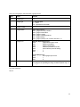
Command
Char
Parameters
Description
<poll>
P
Instr
Poll instrument (return status and error byte)
<control>
C
Instr1
Remotely control an instrument
<release>
R
Instr1
Return instrument to manual control
<reset error>
E
1
Instr
Reset all error flags
<short>
S
Instr
Request a short status report from an instrument
reporting operating status of all gauges
<long>
L
Instr
Request a long status report from an instrument.
<Gauge on>
i
Instr1 N
Switch on ion gauge. Emission current:
N = '0' 100uA
N = '1' 1mA
N = '2' 10mA
N = '3' auto emission control
8
<Gauge off>
o
Instr1
Switch off ion gauge.
<Overpressure>
p
Instr1 SN
Value
Set the ion gauge overpressure trip
<filament>
f
Instr1 F
Select filament F = '1' or '2'
<filter time constant>
s
Instr1 T
Select filter time constant where T = '0':off, '1', '2', '4'
or '8' seconds
<setpoint>
r
Instr Relay
SN Value
Change a relay setpoint pressure.
<override>
O
Instr1 Relay
Permanently energise relay. Command <setpoint>
restores normal operation.
<inhibit>
I
Instr1 Relay
Permanently de-energise relay. Command
<setpoint> restores normal operation.
<display>
d
Instr1 Text
Displays message "Text" up to 24 characters on the
PGC1 LCD display. A blank message clears the
display.
<sound>
n
Instr1 D,T
Using divisor D to divide a frequency of 921600 Hz,
produce a tone for T ms.
1
these instrument addresses may be global, i.e. 'X'.
Examples:
*C2
*CX
*S0
*i01
*n1
*r6C2.0E-10,
control instrument 2
control all instruments
get a short status report from instrument 0
turn on IG in instrument 0 at 1 mA
turn off IG in instrument 1
setpoint relay C, instrument 6 2.0e-10 mbar
9
3:5 Status reports.
There are two types of status report. The short status report gives the operating status and pressure of
each gauge in the instrument. The long status report lists the configuration of each gauge, each relay and
the instrument. The information given by the long status report only needs to be read once after taking
control of an instrument; its information may change during operation, but only predictably in response to
host computer commands. The short report can be requested as often as required.
Pressures.
The pressure measurement for each gauge in the instrument is updated 4 times a second. Pirani and
capacitance manometer gauge pressures are displayed and reported without filtering. Ion gauge pressures
can be filtered with a time constant of 1, 2, 4 or 8 seconds, but filtering can be turned off if desired. The
pressure field for a non-operating gauge is filled with spaces.
Status report formats.
All status reports begin with the status and error characters described above, and terminate with a
checksum and CR-LF combination. The checksum is formed by adding all the preceding bytes, starting with
the status byte, taking the two's complement of the least significant 8 bits. It is sent in hexadecimal as two
characters, the most significant 4 bits first.
Status reports can be read in two ways:
(a) because the CR-LF terminator can only occur at the end of a report the report can be read into a buffer
until the terminator is seen. The report is then decoded into gauge, relay or system records. This is the best
approach on slower machines (such as IBM PCs).
(b) alternatively, the report can be read intelligently and decoded record by record. As each record has a
header character ('G', 'R' or 'S'), and the records are of fixed length, the first character of the checksum
signals the end of the report.
3:5.1 Short status report.
Status byte.
Error byte.
A relay status byte:
The relay status byte is of the form 0100XXXX2, where the least significant 4 bits indicate the state
of each relay (1 = energised). The relay status byte indicates the status of relays 'A' to 'D', with relay
'A' indicated by the least significant bit. The status of a relay assigned to the ion gauge when it is not
in emission is defined in the setup menu; this setting is given in the long status report (see below).
An unused byte.
10
Then, for each gauge in the instrument, a gauge record:
Byte
Name
Details
1
Header byte
'G'
2
Gauge type
'I' : Bayard-Alpert
'P' : Pirani
'M' : capacitance manometer
3
Gauge number
'1' ...
4
Gauge status
Bit 6: always set to 1
Bit 5: gauge externally inhibited
Bit 4: gauge in leak detect
Bit 3: gauge in degas
Bit 2: gauge controlling bakeout
Bit 1: gauge starting
Bit 0: gauge operating (can combine with bits 2 - 4)
5
Gauge error
Bayard-Alpert Gauge error:
Bit 0
:
gauge filament open-circuit
Bit 1
:
gauge overemission
Bit 2
:
gauge underemission
Bit 3
:
maximum pressure exceeded
Bit 4
:
pirani interlock prevents starting
Bit 6
:
1
Bit 7
:
0
Pirani Gauge error:
Bit 0
:
Pirani gauge open-circuit
Bit 6
:
1
Bit 7
:
0
6-13
Pressure
Comma delimited string in scientific notation, e.g. "1.3E-07,". If
the gauge is not operating the string consists of spaces only, i.e.
"
,"
Two-byte checksum.
CR, LF
11
3:5.3 Long status report.
Status byte.
Error byte.
For each gauge, a gauge configuration record:
Byte
Name
Details
1
Header byte
'G'
2
Gauge type
'I' : Bayard-Alpert
'P' : Pirani
'M' : capacitance manometer
3
Gauge number
'1' ...
4
LP filter TC
'0','1','2','4' or '8' (seconds) (BA gauge only)
5
Filament number
'1' or '2' (BA gauge only)
6
Filament type
'0' = Iridium, '1' = Tungsten (BA gauge only)
7
Emission current
'0' = 100uA, '1' = 1mA, '2' = 10mA, '3' = Auto (BA gauge only)
8-9
unused
10-17
Maximum pressure
(mbar) (cold-cathode and
BA gauges)
"N.Ne-NN,"
For each relay, a relay configuration record:
Byte
Name
Details
1
Header byte
'R'
2
Relay letter
'A' - 'D'
3
Status
'0' : associated with gauge
'2' : inhibited (de-energised)
'1' : over-ride (energised)
4-11
Setpoint
Pressure in scientific notation "N.NE±NN,"
12
Associated gauge or
function
'1' = BA gauge
'2' or '3' = Pirani gauges
'4' = Capacitance Manometer
'T' = TSP control
'B' = Bakeout control
System configuration record:
12
Byte
Name
Details
1
Header byte
'S'
2
Pirani 1 interlock
'0' :
'1' :
disabled
enabled
3
Relay configuration
'0' :
'1' :
Ion gauge relay de-energised when ion gauge is off
Ion gauge relay is energised when ion gauge is off
4
Units of measurement
'M' (mbar) 'P' (pascal) or 'T' (torr)
5-9
Program version
4-character ASCII string, e.g. "1.03,"
10-18
Program date
8-character ASCII string, i.e. "DD/MM/YY,"
19-21
Ambient temperature
"NNN" (degrees)
22-25
Capacitance manometer
full scale
"NNNX" where NNN is "1", "10" or "100" and X is either 'M'
(mbar) or 'T' (torr)
26-28
Ion gauge sensitivity
"NNX" where NN is the sensitivity and X is 'M' (mbar) 'P'
(pascal) or 'T' (torr)
29-40
Additional system parameters may be defined in future
Two-byte checksum.
CR, LF
13
Appendix A. Example of a host/PGC1 dialogue.
Source
ASCII
Hex
Description
Host
*P5
2A 50 35
Host polls instrument 5
Instr 5
$@
CR-LF
24 40
0D 0A
PGC1 under local control
Host
*P1
2A 50 31
Host polls instrument 1
Instr 1
4A
CR-LF
34 41
0D 0A
PGC1 under host control, Gauge-specific error
occurred
Host
*S1
2A 53 31
Host requests short report
Instr 1
4A
m@
GI1
A
A
2.7E-03,
Status and error bytes
Relays A,C,D energised
Gauge : Bayard-Alpert gauge 1
On
Error = over emission
Pressure
8D
__
31 41
6D 40
47 43 31
41
41
32 2E 37 45
2D 30 33 2C
47 50 32
41 40
37 2E 35 45
2D 30 33 2C
47 50 33
41 40
31 2E 30 45
2B 30 33 2C
38 44
0D 0A
Host
*E1
2A 45 31
Host acknowledges and clears Instr 1 error flag
Instr 1
4@
CR-LF
34 40
Instrument clears its error byte and indicates
readiness to accept a new command
Host
*o1
2A 6E 31
Host turns off gauge
Instr 1
4@
CR-LF
34 40
0D 0A
Instrument 1 status byte. No error
GP2
A@
7.5E-03,
GP3
A@
1.0E+03,
Gauge record : Pirani Gauge 1
running
Gauge record : Pirani Gauge 2
running
at atmosphere
Checksum
End of report
14
Appendix B. Remote connector.
This is a 9 way "D" type male connector. Used pin connections and signal names for RS232 are:
3
2
5
Received Data
Transmitted data
Signal ground
If option F is present (as indicated by the suffix F in the model number on the rear panel) then the pin
connections and signal names are compatible with RS422 or RS485 as follow:
6
7
8
9
5
1
Received data +
Received data Transmitted data +
Transmitted data Signal ground
Protective ground
15