1
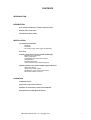
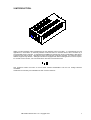
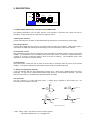
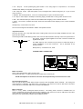
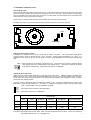
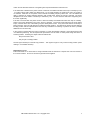
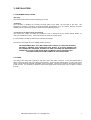
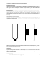
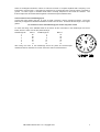
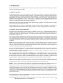
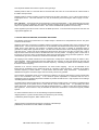
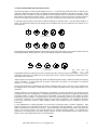
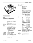
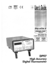
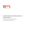
ARUN MICROELECTRONICS LTD.
STEPPER MOTOR DRIVE MODEL SMD1
USER MANUAL ISSUE 1.01
COPYRIGHT RESERVED 1996, 1997
The information contained in this manual has been carefully checked and is believed to be correct. No
responsibility is assumed for any errors. User comment and criticism is welcome: please write quoting the serial
number of the instrument and the version number of the program to:
Customer Services,
Arun Microelectronics Ltd.,
Fitzalan Road,
ARUNDEL,
West Sussex. BN18 9JP.
England.
Please direct other enquiries to the distributor or agent from whom you purchased the instrument.
CONTENTS
INTRODUCTION
DESCRIPTION
2:1 Front Panel Indication, Controls and Connectors.
2:2 Rear Panel Connectors
2:3 Internal Controls (Links)
INSTALLATION
3:1 Instrument installation.
Mounting.
Ventilation.
Connection to the mains supply and earthing.
3:2 Fusing.
3:3 Wiring of the motors to the vacuum feedthrough.
Feedthrough requirements.
Wiring accessories.
Lead identification and interconnection.
Lead Stripping.
Screening the wiring.
Lead connection to the feedthrough pins.
3:4 Wiring between the vacuum feedthrough and the drive
Using AML cables.
Using custom-made cables.
Checking the motor-to-drive connections
Reversal of rotation of motors.
OPERATION.
4:1 Manual Control.
.
4:2 Control via the User Connector.
4:3 Notes on Acceleration, Resonance and Speed.
4:3 Step Division and Angular Resolution.
AML SMD1 Manual Issue 1.01 Copyright 1997
1
2.INTRODUCTION.
SMD1 is a self-contained, mains-powered drive for UHV stepping motors up to B23.1. It is intended for low-cost
applications in stand-alone or externally-indexed modes and also for multi-axis drives when controlled by a
programmable motion controller. It complements the SMD2 and extends the range of applicability of AML drives
at both the high and low-ends. Half-step and wave-drive full-step modes are provided. An enhanced version,
SMD1M, supports step division. Although intended and equipped with thermal management functions required
for use with vacuum motors, it is economical when used with conventional motors.
This equipment meets the intent of the EU EMC Directive 89/336/EEC and the Low Voltage Directive
73/23/EEC.
Certificates of Conformity are available from AML Customer Services.
AML SMD1 Manual Issue 1.01 Copyright 1997
2
2. DESCRIPTION.
>T
RDY
A
JOY
USR
V
1
SMD1 UHV STEPPER MOTOR DRIVE
2:1 FRONT PANEL INDICATION, CONTROLS AND CONNECTORS.
The following descriptions cover the basic function of the indicators, connections and controls and are not
exhaustive. Further information is contained in the operation section.
'1' Mains power indicator.
A green LED indicator is provided: it is illuminated when the instrument is connected to the power supply.
'RDY' Ready indicator.
A yellow LED indicates that the drive is in a condition where the motor may be driven. When mains power is
connected to the SMD1 this indicator illuminates slowly a few seconds after the mains power indicator.
'A' Acceleration control.
This potentiometer controls the rate at which the motor accelerates and retards under the control of the internal
oscillator. The acceleration rate is controlled by the position of this control, so that zero to full speed takes from
a fraction of a second at minimum setting to about a second at maximum. The acceleration time is also
dependent on the setting of the speed control.
'V' Speed control.
This potentiometer controls the rate at which the motor steps or ministeps under the control of the internal
oscillator. The minimum speed is less than 200Hz and the maximum is greater than 5kHz.
'>T' Motor over-temperature indicator.
A red LED indicates that the motor temperature exceeds 175°C. Motor drive is disabled when this LED is
illuminated. An open-circuit or disconnected thermocouple causes an over-temperature indication. This LED
flashes at other times: q.v. NOTEMP in the Operation section for details.
User Connector.
The user connector is a 8 way DIN audio socket.
connections and equivalent circuits are:
A mating plug is provided in the accessory kit.
Pin
+5V
47K
470R
470R
NOTMP
SO
SZ
4V7
CMOS, 5V
4V7
0V
0V
+5V
+5V
47K
470R
NCW
47K
470R
CMOS, 5V
OTHER INPUTS
4V7
4K7
0V
CMOS, 5V
4V7
0V
+5V OR 0V
EQUIVALENT CIRCUITS
1. RDY. Ready, output. High when the drive is ready to operate.
AML SMD1 Manual Issue 1.01 Copyright 1997
3
2. SO. Step out. A short positive-going pulse related to the rising edge SI or equivalent to the internal
oscillator when NGO (on the joystick connector) is low.
3. SZ. Step zero, output. High when phase A only is energised with current flowing from pin 1 to pin 2 of the
motor connector.
4. NOTMP. Not Overtemperature. Low for an overtemperature or open-circuit thermocouple.
5. SI. Step in. Motor steps or ministeps on the rising edge, provided NGO on the joystick connector is low.
6. NCL. Not clockwise limit input. When low this inhibits further stepping in the clockwise direction.
7. NCCL. Not counter- clockwise limit input. When low this inhibits further stepping in the counter-clockwise
direction.
Shell (Screen). Connected to OV, earth.
The use of these signals is described in detail in the operation section.
Joystick Connector.
The user connector is a 3 way DIN audio socket. Mating male connectors are readily available and 180° 5 pin
types are also suitable.
Connecting the AML model SMDJ joystick to this connector allows direction and step control to be performed on
the joystick. Direction signals applied to the User connector override the
joystick NCW signal.
3. 0V
1. NCW
The 'NGO' signal on this connector may be driven to extend the range of
control possibilities of the User Connector. This is described in the
operation section
2. NGO
Shell (Screen). Connected to OV, earth.
JOY
2:2 REAR PANEL CONNECTORS.
100/110V(SMD1L)
230V
(SMD1H)
50/60Hz, 50W
MOTOR
K T/C
MODEL SMD1
SER.No.
Mains Connector.
This is a IEC CEE22 pattern male connector with
an integral fuseholder.. A mating mains lead is included in the accessory kit.
The M5 stud adjacent to the mains connector must be permanently connected to mains earth.
Thermocouple Connector.
This is a Type K flat-pin female thermocouple connector with compatible contact materials. The mating free
male connector is ‘Labfacility’ type FMTC-K-M, or equivalent. This connector is used on AML MLF12 and other
motor leads and is included in AML motor connection kit SMDMCC.
Motor Connector
This is a 4 way ’Trident’ rectangular female connector. The mating male connector is available from ITT
Cannon, Framatome and other manufacturers and suppliers. This connector is used on AML MLF12 and other
motor leads and is included in AML motor connection kit SMDMCC.
Wiring of motors is described in detail in the installation section.
AML SMD1 Manual Issue 1.01 Copyright 1997
4
2:3 INTERNAL CONTROLS (Links).
Removing the cover.
Disconnect the mains lead before removing the cover. If the mains lead is removed when the motor is not being
driven the energy stored in the capacitors is discharged over a few seconds. The persistence of this energy
store is indicated by the ‘RDY’ LED on the front panel. For this reason the drive should not be connected to the
mains when the cover is not fixed to the chassis.
Remove the four screws at the sides near the ventilation slot and lift the cover upwards.
The fifth screw in the cover which is situated near the mains connector, must not be removed.
LK2
LK1
LINKPARK
FUSE
Setting the motor phase current.
Instruments are shipped with the phase current set to 500mA, for safety. The recommended initial phase
current for B23.1 motors is 500mA and for B14.1 and B17.1 motors driving mechanisms it is 1 amp. It is
probable that the motor can be run at lower phase currents in most applications and this will decrease the gas
load.
LK1
0.25A
0.5A
0.75A
1.0A
Phase currents are set by fitting a single link to LK1. Fit the link in one of the four locations shown
in the diagram at the left, corresponding to the desired current. A link must be fitted or the phase
current will be indeterminate. Spare links are stored on "LINKPARK”
Setting the drive step mode.
SMD1 provides either full step wave drive or half step drive to the motor. SMD1M provides in addition step
division by 4,8,16 or 32. Wave drive provides the phase current to only one of the two phases at any one time.
All the other drive modes provide currents to both phases and the direction and magnitude of these is varied,
according to the substep position.
The drive mode is selected by fitting combinations of links to LK2. The used combinations are shown in the
table below, where XXX denotes a link. All unused or undefined combinations result in full step mode being
used. Modes marked * are only available in SMD1M.
LK2
MS0
MS1
MS2
HOLD
The function of the hold link is described below.
Spare links are stored on "LINKPARK”.
DRIVE MODE
FULL
MS0
MS1
MS2
HALF
QUARTER
XXX
XXX
EIGHTH*
SIXTEENTH*
XXX
XXX
XXX
XXX
THIRTY-SECOND*
XXX
XXX
XXX
XXX
XXX
Setting and function of the HOLD link.
Instruments are shipped with this link fitted. Most uses will require the link to be fitted. Only if very infrequent
AML SMD1 Manual Issue 1.01 Copyright 1997
5
motion and the absolute minimum of outgassing are required should the link be removed.
If the HOLD link is fitted then the phase current is reduced 100 milliseconds after each step or ministep by 50%.
If a further step is taken within 100 milliseconds, e.g. for steady stepping at greater than 10Hz, the current is
not reduced. Reduction of the phase current reduces the holding torque by about half. The 100 millisecond
delay is sufficient to achieve sufficient damping with normal loads, before the torque is reduced. The power
dissipated in the motor while it is stationary is reduced by 75%. In most cases this will reduce outgassing from
the motor significantly.
If the link is not fitted then the phase current is removed entirely 100 milliseconds after each step or ministep.
There is zero power dissipation in the motor when it is stopped. The torque is then reduced to the motor detent
torque, which is about 10% of the holding torque at rated phase current. If any drive mode other than full-step is
being used then the motor will relax into an adjacent full step position. The direction of rotation into the adjacent
full step position will be indeterminate and so that any mechanism for tracking of position will have a possible
additional error of half a step.
If zero power is required when the motor is stopped ( i.e. when the hold link is absent ) and a step-division mode
and absolute positioning are all required then precautions must be taken to avoid power being removed at a
sub-step position. Following two simple rules will achieve this.
Step at more than 10Hz.
Only stop at a full step position.
The SZ signal will help to track full step positions
rotating in a consistent direction).
This signal is high for every fourth full-step position (when
Replacing the cover.
Ensure that there are no loose links or foreign material inside the instrument. Replace the cover and screws in
the correct locations. Do not use screws longer than those supplied.
AML SMD1 Manual Issue 1.01 Copyright 1997
6
3. INSTALLATION
3:1 INSTRUMENT INSTALLATION.
Mounting.
The instrument is intended to be free-standing on its feet.
Ventilation.
The instrument is ventilated by convection through grilles on the sides top and base of the case. The
instrument is tolerant of operation at elevated ambient temperatures up to 30° Celsius, although long-term
reliability will be enhanced by operation at the lowest possible temperature.
Connection to the mains supply and earthing.
The nominal line voltage for which the instrument is set is determined by the model number SMD1L for
100/110V or SMD1H for 230V. The model number is printed on the rear panel.
It is not possible to modify the instrument to alter the line voltage.
The mains is connected via an IEC CEE22 pattern connector.
THE INSTRUMENT MUST ALSO BE CONNECTED TO EARTH BY THE STUD PROVIDED.
FAILURE TO PROVIDE THIS CONNECTION MAY RESULT IN A SHOCK HAZARD FOR
THE OPERATOR IF EXTERNAL SOURCES OF HIGH VOLTAGES ARE INADVERTENTLY
CONNECTED TO THE OTHER LEADS WHEN THE MAINS LEAD IS DISCONNECTED.
SUCH MIS-CONNECTIONS ARE COMMON IN VACUUM SYSTEMS.
3:2 FUSING.
The rating of the mains fuse is printed on the cover next to the mains connector. It must be replaced with a
20mm x 5mm anti-surge fuse of the same type and rating. Such fuses are marked with a "T" next to the current
rating: ceramic fuses are generally unsuitable, even if so marked. The fuse is mounted on the mains connector,
inside the case. It is necessary to disconnect the mains supply before removing the cover to inspect or replace
the fuse.
AML SMD1 Manual Issue 1.01 Copyright 1997
7
3:3 WIRING OF THE MOTORS TO THE VACUUM FEEDTHROUGH.
Feedthrough requirements.
Each motor requires six vacuum feedthrough pins. Any instrumentation feedthrough should be suitable. All
AML motors are provided with a K-type Thermocouple (Chromel/Alumel) embedded between adjacent windings,
which must be used for over-temperature protection. It is not necessary to use a thermocouple vacuum
feedthrough, as the error introduced by incompatible feedthrough material is not significant.
Wiring accessories.
AML supply a kit, MLF12, consisting of a 12-way feedthrough, bakeable external lead and internal connectors.
The kit is suitable for one or two motors and two SMD1s. Motors can be supplied ready-wired to an in-vacuum
connector, MLF12VCF, which simply plugs onto the inside of the feedthrough. Where two motors share the
same feedthrough or on multi-axis mechanisms it is convenient to wire each motor to an AML VTB6 vacuumcompatible terminal block and have a permanent wiring installation between the terminal block and the
feedthrough.
Lead identification and interconnection.
Current AML motors have self-coloured polyimide covered leads without marking. The thermocouple wires are
much thinner than the power wires. The Alumel wire (conventionally sleeved in blue) may be identified with a
magnet, since it is weakly magnetic.
B-Series Motors e.g. B23.1 and B14.1 have windings optimised for use with AML drives and only require
connecting to the feedthrough. The two phase windings are identical and arbitrarily designated FA and FB.
Identify the separate phases with an ohmmeter.
Lead stripping.
The motor leads are supplied pre-stripped at their extremities. To strip cut leads use a high-speed rotary
stripper or cut a ring round the insulation with a scalpel, taking care not to mark the wire. The insulation is not
bonded to the wire and the cut portion can be withdrawn over the end of the wire. Do not attempt to use thermal
strippers on polyimide insulation.
Screening the wiring.
AML SMD1 Manual Issue 1.01 Copyright 1997
8
There are rectangular waveforms of about 70 volts and currents of 1 ampere amplitude with a frequency of 20
kHz present on these wires. If the leads are required to be screened then the screen should be connected to
ground. An OFHC copper or stainless steel braid is normally adequate for this inside the chamber. The
thermocouple wires should be twisted together to minimise the space between them.
Lead connection to the feedthrough pins.
Connect the motor leads to the pins by crimp or barrel connectors. MLF12 includes connectors. The motor
leads are pre-stripped and should be doubled for insertion into the bore. Thread the wires through a new copper
gasket.
Do not bend or stress the feedthrough pins as this may cause a leak.
To match the wiring of the bakeable leads in the MLF12 kit the connections to the feedthrough must be as
follow, where ÞA and ÞÞ are the two phase windings:
Feedthrough Pin
1
2
3
4
5
6
Motor 1
FA
FB
FA
FB
P
N
Feedthrough Pin
7
8
9
10
11
12
Motor 2
FA
FB
FA
FB
P
N
After wiring the motor to the feedthrough check the phase and thermocouple
resistances with an ohmmeter for correct connection and for unwanted shorts.
AML SMD1 Manual Issue 1.01 Copyright 1997
9
3:4 WIRING BETWEEN THE VACUUM FEEDTHROUGH AND THE DRIVE.
Using AML cables.
Users of the MLF12 kit need only to connect the bakeable connector to the air side of the feedthrough and the
other connectors to the SMD1. MLF12 cables are screened. The screen is brought out to a flying lead which
must be connected to the SMD1 earth stud.
Using custom-made cables.
The thermocouples should be connected to the instrument with K-type extension cable using the connector in
the accessory kit. Thermocouple extension cable is readily available, inexpensive and normally suitable for use
in bakeout zones and should be used wherever possible. Take care to ensure consistent polarity throughout
and connect the blue Alumel wire to the connector pin marked "-". Signal voltages from thermocouples are very
small so some precautions against induced interference are desirable. Insulated thermocouple wires or
extension cables should be twisted together to avoid magnetic induction and routed away from power cables.
K T/C
_
+
Since the current and voltage on the
drive are small the phase wiring can be of relatively
2
small cross-section, and 16/0.2mm (
0.5mm or AWG20 ) wire is recommended. Twisting
the pairs of wires for each phase together throughout their length will reduce radiated interference. An overall
screen is recommended.
Pin connections on the 'Trident' motor connector is shown related to the two arbitrarily-designated windings:
MOTOR
1. PHASE A
2. PHASE A
3. PHASE B
4. PHASE B
Checking
the
motor-to-drive
connections.
It is essential that the drive, wiring and motor combination work properly before closing the vacuum system. The
simplest check is to measure the resistances between pins on the motor and thermocouple connectors before
they are connected to the SMD1 drive. Between pins 1 and 2 of the motor connector you should measure
approximately the phase resistance of the motor. If the cables are several metres long the measurement may
be increased by a few ohms. A similar resistance should be measured between pins 3 and 4. Between pins 1
and 3 there should be an open circuit. Check that there is an open-circuit between both phases and the vacuum
chamber ground. The resistance between the pins of the thermocouple should be a few tens of ohms and there
should be an open circuit to the motor connector. Reconnect the drive and exercise the motor using the joystick
or 'Step' and 'Direction' switches.
Reversal of rotation of motors.
Since the phases are not identified there is a 50% probability that the direction of rotation will be reversed from
the desired or conventional sense. To reverse the direction exchange the connections to only one of the
phases.
AML SMD1 Manual Issue 1.01 Copyright 1997
10
4. OPERATION.
Ensure that the motor and thermocouple connectors are properly connected before inserting the mains
connector or switching on the supply.
4:1 MANUAL CONTROL.
An AML joystick, SMDJ, may be connected to the front panel ‘JOY’ connector. This has a toggle switch for
control of direction and a push-button switch for stepping. A single brief push on the button will cause the motor
to execute a single step or ministep, as defined by the internal links. If the button is held down then the motor
will accelerate, according to the setting of the ‘A’ and ‘V’ controls on the front panel. When the button is
released the motor will retard to a stop. The direction of rotation can only be changed while the motor is
stationary. If the toggle switch is moved when the motor is moving this will be ignored until the motor has
stopped. The NGO signal is low when the button is pressed.
Some practice may be necessary to achieve single stepping using the joystick. Very brief presses, no faster
than two or three per second should be used.
Erratic stepping may be caused by inappropriate settings of phase current, acceleration, step division or
maximum speed for the load inertia or friction. Refer to section 4:3, below for general advice on these points.
4:2 CONTROL VIA THE USER CONNECTOR.
The inputs on the User Connector may be driven by 5V CMOS or LSTTL logic. A 47k internal pullup resistor is
provided, so that unused inputs are in a defined state. The use of contact closures to drive inputs is not
recommended, other than for limit switches. The inputs and outputs are protected against mis-connection to
voltages in the range ±15v DC.
SI. The motor will step or ministep on a positive transition of the Step Input (SI), provided the NGO signal on the
‘JOY’ connector is high (when the button is not being pressed of if the joystick is not connected). The SI signal
must remain high for 100ms, minimum and have a maximum frequency of 5kHz. The maximum frequency and
acceleration for which the motor will step reliably is defined by the motor characteristics, phase current and load
conditions.
NCW. When this input signal is low the motor will step in a clockwise direction, when it is high the motor will
step in a counter-clockwise direction. This input overrides the direction commanded on the ‘JOY’ connector.
The state of this input must only be changed when the step rate is such that the motor is able to respond to a
reversal of rotation, otherwise synchronism will be lost.
SO. This signal follows the SI input. A 100ms positive-going pulse is produced after every positive transition of
the SI input. When the joystick or equivalent is used (i.e. when NGO on the ‘JOY’ connector is low) then SO
follows the internal oscillator. This signal enables the controlling system to track motion, whether this is
controlled by the SI input or by the joystick..
SZ. This signal is high when only phase A is energised in the positive direction. This occurs on every fourth
step for full-step control, every eighth step for half-stepping etc., in a consistent direction. This signal is useful
for tracking full-step positions, which are the only ones where the motor power can be removed without altering
the rotor position. Step zero condition is established after the mains supply is connected. If position is to be
preserved while the supply is disconnected it is necessary to leave the motor at a step-zero position.
RDY. This output signal is high when the drive is ready to operate. When the mains supply is connected It
remains low for 3 seconds then pulses at 100Hz for 1.2 seconds. It is low when there is a fault condition. Fault
conditions include a short- circuit across or between motor phases or from a phase to ground.
NOTMP. The ‘>T’ LED is driven by this signal and is illuminated when NOTMP is low. NOTMP indicates either
that the motor is too hot or that some other fault or a microprocessor reset condition has occurred.
NOTMP goes low when the thermocouple indicates that the motor is at >175°C or if the thermocouple is opencircuit or disconnected. If this occurs then step commands are accepted for 1.3 seconds, to allow the motor to
be retarded and stopped without loss of a record of its position, (at a full-step or step- zero position). Phase
current is then removed and the RDY output set low until the motor cools by 10 to 15° or until the thermocouple
is reconnected. The state of the phase currents (the step and substep number) is preserved during an overtemperature condition.
If the NGO signal is low when an overtemperature condition is cleared the NOTMP output pulses at 0.5Hz and
motor power remains off until NGO goes high.
NOTMP will pulse at 1Hz for 3 seconds following connection of the mains. If NGO is low at the end of the 3
AML SMD1 Manual Issue 1.01 Copyright 1997
11
second period NOTMP will continue to pulse until it goes high.
NOTMP pulses at 2Hz for 3 seconds after an external reset and at 4Hz for 3 seconds after an internal reset of
the SMD1 microprocessor.
NOTMP pulses at 10Hz if excessive current is drawn from the motor connector, e.g. by a short-circuit output or
inappropriate motor. This fault indication can only be cleared by disconnecting the mains supply from the
SMD1.
NCL and NCCL. These inputs are the clockwise and counter-clockwise limits. If the clockwise limit input goes
low when the motor is stepping in the clockwise direction stepping action in that direction is inhibited and only
steps in the opposite direction have an effect. The counter-clockwise limit operates in the same way.
These signals may be used to force a reset of the SMD1 processor. To do this both limit inputs must be low and
eight pulses applied to SI.
4:3 NOTES ON ACCELERATION, RESONANCE AND SPEED.
The following notes are an introduction to a complex subject. References to comprehensive sources are given
at the end of this section.
Stepping motors are moved from one detent position to another by the magneto-motive force produced by the
phase current. The rotor and load inertia has to be accelerated and retarded and frictional forces opposed. No
useful work is done after the new position is reached. When the motor is rotating at significant speed it
generates a voltage which opposes the drive. The self and mutual inductance of the windings oppose changes
of phase current. Energy has to be supplied and removed from the motor by the drive for each step. After a
step has been taken the rotor tends to oscillate about the new rest position. At stepping rates of more than a
few tens of Hz the rotor does not stop between steps and its stored kinetic energy becomes significant. These
characteristics give rise to resonances, and limits to acceleration and speed.
All stepping motors exhibit resonances at low frequencies, usually below 100Hz and again at 500Hz to kHz,
when unloaded. These frequencies cannot be stated with any precision, as they are affected by the load and
drive conditions. Load inertia reduces the resonant frequency. Increasing the phase current usually increases
the lower resonant frequency.
Operation at or near the resonant frequencies can cause erratic stepping. This can be alleviated at low
frequencies by ministepping or by starting the motor at a frequency above resonance. Operation at the higher
resonant frequency is best avoided. A small friction load will often damp resonances. Acceleration or
retardation through the resonance region does not usually result in any problem.
The maximum acceleration which can be sustained is related to the energy interchange so larger inertia loads
have to be accelerated more slowly. If the maximum speed requirement is consistent with the use of
ministepping then the greatest step division available or possible should be used. Higher phase current settings
will allow greater accelerations.
At speeds above 1Khz the inductance of the windings becomes a limiting factor, since there is insufficient time
during each step for the phase current to reach the set current in full-step mode. It is principally this effect
which causes the torque of the motor to fall with increasing frequency. In B23.1 motors the motional voltage is
also significant. For this reason it may be desirable to reduce the acceleration to achieve the highest possible
speeds.
For more information refer to one of the following inexpensive textbooks:
‘Stepping Motors: A guide to modern theory and practice” by PP Acarnley,
published by Peter Peregrinus, ISBN 0 86341 027 8
or
‘Stepping Motors and their Microprocessor Controls’ by Takashi Kenjo
published by the Clarendon Press, ISBN 0 19 859339 2
AML SMD1 Manual Issue 1.01 Copyright 1997
12
4:3 STEP DIVISION AND ANGULAR RESOLUTION.
The basic step angle of an AML hybrid stepper motor is 1.8°. At the full step positions the teeth on half the rotor
poles are in alignment with rotor teeth. On adjacent steps the teeth are aligned on the other set of poles. These
positions are also a condition of minimum reluctance for the magnetic circuit, so that the rotor will relax to a full
step position in the absence of phase current. The torque required to move the rotor from one step position to
the next is the detent torque when the phase current is zero or the pullout torque when there is phase current.
In full step mode the phase current flows in different windings on alternate steps. If the two phase windings, A
and B, are visualised as being at right angles then the resultant flux can be considered to be rotating 90° on
each step thus:
A+
A+
B+
B
A
_
_
CLOCKWISE ROTATION
A+
A+
B
_
B+
_
A
COUNTER-CLOCKWISE ROTATION
If both phases are energised with equal currents then the flux vector will swing to a 45° position and the rotor will
step halfway between detent positions. Part of a half-stepping sequence is shown below:
A+
A+
R
B+
B+
B+
A
CLOCKWISE ROTATION
HALF-STEPPING
_
R
A
_
The rotor may be
moved
to
an
intermediate position by scaling the currents in phases A and B to swing the angle of the resultant. The physical
movement of the rotor is one fiftieth that of the notional flux vector. By this means greater subdivisions of the
step angle can be achieved.
SMD1 supports full, quarter and half step modes and SMD1M supports eighth, sixteenth and thirty-second step
modes, in addition. To aid tracking the SZ signal is high when only phase A is energised in the positive
+
direction, i.e. A in the diagrams.
The principal advantages of ministepping are that the transient impulse given to the rotor is much reduced and
the damping factor is increased. These lead to much smoother low-speed rotation and greater freedom from
resonance.
Angular resolution can be improved somewhat by step-division, but there are limits to the degree and the
circumstances when this is appropriate. The differential torque between ministeps is progressively reduced with
increasing number of steps; when this becomes comparable to the static friction in the system no further
improvement can be obtained. The positional error due to the manufacturing tolerances are fixed at about 4%
of a full step. Generally, it is not possible to obtain an improvement of resolution of an unloaded motor better
than can be achieved by quarter or eighth stepping, unless some feedback device is available to close the
control loop.
In UHV applications it is always important to run the motor at minimum power, to reduce outgassing. With
SMD1 the ‘HOLD’ link must be fitted if the motor is to be stopped at sub-step positions. In this case the motor
power is reduced by 75% when it is not moving. If the ‘HOLD’ link is not fitted then the power is zero when the
motor is not moving, however, the rotor will relax into an adjacent full-step position. For ultimate UHV
performance it is usually better to increase angular resolution by using anti-backlash reduction gears and only
stop the motor at full-step positions than to use step division.
END.
AML SMD1 Manual Issue 1.01 Copyright 1997
13