1
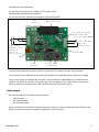
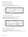
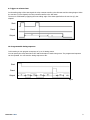
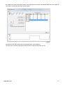
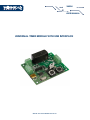
VM206
MODULES
USER MANUAL
UNIVERSAL TIMER MODULE WITH USB INTERFACE
WWW.VELLEMANPROJECTS.EU
Table of contents
Description
3
Features and specifications
3
Plugging in your board for the first time
4
Starting the software
4
Timer operation modes
4
Relay output
5
Description of the timer operation modes
6
Timing sequencer user interface
10
Let’s get started!
Description
No timer is universal, except this one!
2 reasons why this timer is truly universal:
1. The timer comes with a wide variety of operating modes.
2. If the built-in modes or delays don’t suit your application, you can simply tailor them according to your
needs using the supplied PC software.
Features
•
•
•
•
•
10 operating modes:
- toggle mode
- start/stop timer
- staircase timer
- trigger-at-release timer
- timer with turn on delay
- timer with turn off delay
- single shot timer
- pulse/pause timer
- pause/pulse timer
- custom sequence timer
wide timing range
buffered inputs for external START / STOP buttons
heavy duty relay
PC software for timer configuration and delay setting
Specifications
•
•
•
•
•
power supply: 12 VDC (100 mA max.)
relay output: 8 A / 250 VAC max.
minimum event time: 100 ms
maximum event time: 1000 h (over 41 days)
dimensions: 68 x 56 x 20 mm (2.6” x 2.2” x 0.8”)
USER MANUAL VM206
3
Plugging in your board for the first time
First, you will need to plug your VM206 into an available USB port on your computer so Windows can
detect your new device.
Then download the latest software version for the VM206 on www.velleman.eu via these simple steps:
1. go to: http://www.vellemanprojects.eu/support/downloads/?code=VM206
2. download the VM206_setup.zip file
3. unzip the files in a folder on your drive
4. double click the “setup.exe” file
An install wizard will guide you through the complete installation procedure. Shortcuts to the VM206
software can now be installed.
Starting the software
1. locate the VM206 software shortcuts
(programs > VM206 > ...).
2. click on the icon to start the main program
3. then click on the ‘Connect’ button,
the “Connected” label should now be
displayed
You are now ready to program the VM206 timer!
fig. 1
Timer operation modes
1:
2:
3:
4:
5:
6:
7:
8:
9:
on delay - relay turns on after delay t1
off delay - relay turns off after delay t1
one shot - a single pulse of length t2, after delay t1
repeat cycle - after delay t1, relay turns on for t2 ; then repeats
repeat cycle - relay turns on for time t1, off for t2; then repeats
toggle mode
start/stop timer
staircase timer
trigger-at-release timer
10: programmable timing sequence
Now you can set up your first timing program for the VM206:
1. select any of the options from 1 to 9
2. enter the time or use the default 2sec and 1sec
3. now click the ‘Send’ button
USER MANUAL VM206
4
The VM206 is now programmed!
You can check the operation by pressing the TST1 (Start) button.
The ‘RELAY ON’ LED indicates the operation.
You can stop the timer operation by pressing the TST2 (Reset) button.
Power
supply
Heavy duty relay
12 VDC / 100 mA max.
For inductive loads,
add optional VDR
(e.g., Velleman VDR300)
8 A / 250 VAC
NO / NC
Relay output
Start - Stop
Buffered inputs
accept dry
contact or
open collector
Status LEDs
USB
ICSP
connector
Start - Reset
pushbuttons
fig. 2
To get the relay functioning as well, you need to connect the 12 V supply to the SK1 screw connector.
You can disconnect the USB cable and test the timer operation as a stand-alone device with the 12 V supply.
There are two inputs on the board; IN1 and IN2 for remote switches or NPN transistors to control the timer
operation. The switch or transistor connected between IN1 and GND acts as the Start button (TST1) and the
switch or transistor connected between IN2 and GND acts as the Reset button (TST2).
Relay output
The relay contacts are connected to the SK3 connector:
•
•
•
COM: Common
NO: Normally Open
NC: Normally Closed
Space is provided on the board for a transient suppressor (option) to reduce contact wear. Mount VDR1 for suppression of the NC contact. Mount VDR2 for suppression of the NO contact.
USER MANUAL VM206
5
Description of the timer operation
1: On delay - relay turns on after delay t1
Timing begins on the leading edge of the Start signal.
When the set time (t1) has elapsed, the relay contacts transfer to the ON state.
The contacts remain in the ON state until the Reset signal is applied or power is interrupted.
Start
Reset
Output
fig. 3
2: Off delay - relay turns off after delay t1
When a Start signal is supplied, the relay contacts transfer immediately to the ON state.
Timing begins on the trailing edge of the Start signal.
When the set time (t1) has elapsed, the relay contacts transfer to the OFF state.
The timer is reset by applying the Reset input or by interruption of power.
Start
Reset
Output
fig. 4
3: One shot - a single pulse of length t2, after delay t1
Timing begins on the leading edge of the Start signal.
When the first set time (t1) has elapsed, the relay contacts transfer to the ON state.
The contacts remain in the ON state until the second set time (t2) has elapsed or the Reset signal is applied
or power is interrupted.
USER MANUAL VM206
6
Start
Reset
Output
fig. 5
4: Repeat cycle - after delay t1, relay turns on for t2; then repeats
Timing begins on the leading edge of the Start signal.
A cycle is initiated when the output will be OFF for the first set time (t1), then ON for the second set time (t2).
This cycle will continue until the Reset signal is applied or power is interrupted.
Start
Reset
Output
fig. 6
5: Repeat Cycle - relay turns on for time t1, off for t2; then repeats
Timing begins on the leading edge of the Start signal.
A cycle is initiated where the output will be ON for the first set time (t1), then OFF for the second set time (t2).
This cycle will continue until the Reset signal is applied or power is interrupted.
Start
Reset
Output
fig. 7
USER MANUAL VM206
7
6: Toggle mode
When a Start signal is supplied, the relay contacts transfer immediately to the ON state.
When the Start signal turns ON again, the relay contacts transfer to the OFF state and on the next Start signal
to ON state etc.
Start
Reset
Output
fig. 8
7: Start/Stop timer
When a Start signal is supplied, the relay contacts transfer immediately to the ON state and the set time (t1) begins.
When the set time (t1) has elapsed, the relay contacts transfer to the OFF state.
The timer is reset by applying the Start signal before the set time (t1) has elapsed.
Start
Reset
Output
fig. 9
8: Staircase timer
When a Start signal is supplied, the relay contacts transfer immediately to the ON state and the set time (t1) begins.
When the set time (t1) has elapsed, the relay contacts transfer to the OFF state.
The timer is reactivated by applying the Start signal before the set time (t1) has elapsed.
Start
Reset
Output
fig. 10
USER MANUAL VM206
8
9: Trigger-at-release timer
On the trailing edge of the Start signal the relay contacts transfer to the ON state and the timing begins. When
the set time (t1) has elapsed, the relay contacts transfer to the OFF state.
The timer is reactivated by applying the next trailing edge of the Start signal before the set time (t1) has
elapsed.
Start
Reset
Output
fig. 11
10: Programmable timing sequence
In this mode you can program a sequence of up to 24 timing events.
You can specify the relay state ON or OFF and the duration of each timing event. The programmed sequence
can be repeated. You can save the timing sequence to file.
Start
Reset
Output
fig. 13
USER MANUAL VM206
9
Relay state
Time fields
Timing event list
fig. 14
Timing sequence user interface
Options:
•
•
•
•
•
•
add timing / insert timing
delete timing
copy timing
repeat
sustain the first state until Start signal is OFF
auto start & repeat
By selecting the option ‘Sustain ...’, the relay state of the first timing event is sustained as long as the
Start signal is ON or the Start button is kept pressed down.
Start
Reset
Output
fig. 15
USER MANUAL VM206
10
By selecting the option ‘auto start & repeat’, the timing sequence restarts automatically when the power supply is
connected or when there has been a power outage.
fig. 16
Normally the relay will be OFF after the last timing event of the sequence.
The relay can be forced to stay ON by setting the time of the last ‘ON’ action to zero.
USER MANUAL VM206
11
Velleman nv, Legen Heirweg 33 - Gavere (Belgium)
Vellemanprojects.com
ORDERCODE: VM206
REVISION: HVM206’1
UPC
@Velleman_RnD
EAN
/Velleman-nv