1
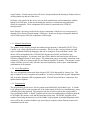
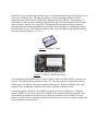
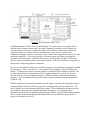
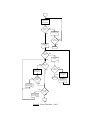
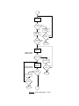
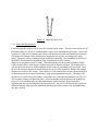
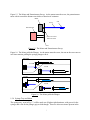
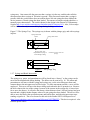
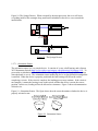
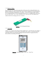
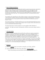
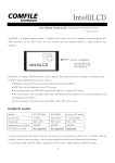
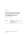
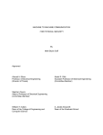
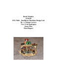
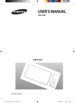
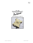
Alternative Design 2 Report
Automatic Syringe Loading Device
Team 2
Daniel Littleton
Scott Relation
Kathryn Tempe
October 26, 2007
Client Contact:
Dr. John Enderle
Biomedical Engineering, University of Connecticut
Email: [email protected]
Phone (860) 486-5521
Alternative Design Project 2
1.1 Introduction
This is an alternative design for an automated syringe-loading device. The goal of this device is to
allow diabetes patients with a variety of disabilities to be able to prepare their insulin injections
without requiring any assistance or supervision from others. The automated syringe loading
device will allow users to specify data and commands though the use of a touch screen display, in
addition to accepting spoken commands from the user. Prompts, data, and error messages will be
presented to the user visually, using large characters on an LCD Display, and audibly using
synthesized speech.
This design differs from the previous design in several ways. Design 1 utilized a laptop as its main
component; it was used a display, a processor, and a touch & sound input device. Instead of a
laptop, the current design uses several individual components to accomplish the same tasks. A
touch input enabled LCD Display (the IntelliLCD) is now used to present information graphically
to the user and to get touch screen commands from the user. A CUBLOC microprocessor (the CB405) will be used to run programs to monitor data from the device’s sensors, communicate with
LCD Display and sound synthesizer chip, operate the device’s motor and servo, and implement a
simple menu interface for the user to interact with. Design 1’s programming was to be written
using Visual Basic; in Design 2 programs will be written using BASIC and Ladder Logic. While
the BASIC program will run sequentially, similar to what would be done in Design 1’s Visual
Basic program, the Ladder Logic program will run using parallel processing. This programming
method will allow the microprocessor to gather data from sensors and control components in real
time.
Sound input will be handled by a sound recognition chip (the RSC-4128), as opposed to relying on
a software package (Dragon Naturally Speaking), such as that used for Design 1. Although this
chip will be somewhat limited in the number of words that it will be able to recognize from voice
input, its major advantage over Design 1’s software is that it is speaker independent; it will not
require any voice training in order for its pattern recognition processing to work. This sound chip
will also be used to synthesize speech for system prompts and other audio output.
The syringe platform assembly has been modified from Design 1; the syringe is now incased in a
moveable drawer which will be accessible from the rear of the device. The C-shaped guides for
holding the syringe have been replaced with grips which will maintain its position while allowing
easier access for insertion and removal of the syringe. The previous Design 1 accomplished
movement of the platform through the use of a linear gear; in the current design a screw gear has
been implemented. Previously the stopping of the servo motor was controlled using a sensor; in
this design precision movement of the servo will be done using the microprocessor.
The bottle holding assembly has been altered from the original design; instead of implementing an
expanding plastic sleeve, a housing will be constructed with four flexible metal brackets.
Additional space with be left between the brackets to make it easier for users to reach in and
1
extract bottles. A bottle removal tool will also be incorporated into the housing to further aid users
in lifting bottles up and out of the device.
In Design 1 the sensors for the device were pre-built modules that could communicate with the
laptop via its USB port. In the current design the sensors are constructed using individual
electrical components. These components will be directly connected to the CUBLOC
microprocessor.
In the Design 1 the energy needs for the various components of the device were met mostly by
drawing power directly from the laptop’s USB ports. In this new design, rechargeable batteries
will be used to power all of the components of the design.
1.1.1 Monitor/Touch Screen
The monitor used to display prompts and insulin dosage amounts, is the IntelliLCD iTL710 by
Comfile. It is a fully colored touch screen monitor. The device has a variety of font sizes and
styles, in addition to different languages, that can be changed to fit an individual’s needs. The
device will be intergraded with a CUBLOC405 chip that uses BASIC and Ladder Logic
programming languages. A real-time clock chip will be added to the board to provide the user
with time-stamped records of doses drawn. The information can be accessed by connection to the
computer by USB or by removing the SD card from the IntelliLCD monitor. The monitor’s touchscreen will allow users to easily select the amount of insulin they wish to inject with additional
confirmations of the amount.
1.1.2 Voice-Recognition
The voice recognition system used in the design is RSC-4128 chip model by Sensory, Inc. This
chip is capable of voice recognition and synthesis. It can be used with either speaker independent
(SI) or speaker dependent (SD) recognition modes. The RSC board will have connections for a
speaker and microphone.
1.1.3 Programming
The programming for the device will be written using both BASIC and Ladder Logic. A Ladder
Logic program will be used to monitor all of the sensor inputs of the device simultaneously, using
a parallel processing approach. This program will also be used to operate the syringe loader’s
servo and plunger motor. A BASIC program will be used for sending and receiving data from the
LCD Display, the memory card, and the sound processing chip. The BASIC program will be
capable of accessing the memory area of the Ladder Logic program; by manipulating data in this
area it will be able to initiate Ladder Logic processing in response to data from the sensors and
commands from the user.
2
1.1.4 Bottle Holder
Flexible metal brackets will bend to conform to the sides of the insulin bottle and hold it top-down
centered over the syringe needle port. A built-in removal tool will aid in the extraction of bottles
from the device.
1.1.5 Motor and Potentiometer
A DC motor will be used to pull the plunger of the syringe and fill it to the desired dosage. To
ensure accuracy, the motor will turn a potentiometer while pulling the syringe plunger. The
computer will read the potentiometer resistance, and through the use of a simple math algorithm
the microprocessor will be able to tell how far the plunger has been pulled. The motor will always
be connected to the plunger claw, which attaches to the syringe.
1.1.6 Syringe Tray and Motor
The syringe tray will be made out of lightweight aluminum, with groves for the syringe, and a slot
for the plunger grip to slide though. Two sensors will be incorporated into tray: one sensor for
detecting the presence of the syringe, and the other for indicating its size (50 units vs. 100 units).
1.1.7 Bottle and Syringe Interaction
When the computer has reached the step where the syringe connects with the insulin bottle for
filling, a servo is activated. This servo will slide the syringe tray along groves under the tray,
moving it into position. A metal cone will help direct the syringe needle into the opening in the
insulin bottle. When the syringe has been filled, the servo will move the tray back to its original
place for removal.
1.1.8 Rechargeable Batteries / Charger
The components for the automated syringe loader will be powered by rechargeable batteries. A
charger module will be incorporated into the device to allow it to be plugged into a standard wall
outlet for charging.
1.1.9 Case Layout
A plastic case will enclose the automated syringe loading device. The front of the case with have a
vertically positioned touch screen monitor, a microphone, and a speaker. The bottle loader door
(on the top on the device) and syringe loading door (located in the lower right portion of the
device) will be secured using Velcro flaps.
1.2 Subunits
3
1.2.1 Monitor/Touch Screen: IntelliLCD
The intended monitor for the design is expected to be IntelliLCD iTL710 by Comfile
(cubloc.com). It is relatively inexpensive compared to laptop alternatives. Similar to the once
considered portable PC, IntelliLCD has a screen size of 7 in. diagonally. The IntelliLCD screen is
also colored and is powered by ~24 V. It features a 1 GB secure digital (SD) card that is
removable and can be upgraded with a maximum of 2 GB.
Figure 1: Example IntelliLCD Interface Design with Dimensions (in mm)
With timekeeping chip, such as the DC1302, the device will be capable of keeping time-stamped
records of doses drawn. The chip contains a real-time clock/calendar and 31 bytes of SRAM. By
a simple serial interface, the chip communicates with the CUBLOC. The clock operates in either
24- or 12-hour format with AM/PM indicators. The clock/calendar provides seconds, minutes,
hours, day, date, month, and year information and is automatically adjusted for months with less
than 31 days and also makes corrections for leap year [1].
Additional input slots included on the IntelliLCD are a USB host and device (ActiveSync), RS232,
serial port (5 V), and a communications speed switch. ActiveSync software is used to link
IntelliLCD with a PC. Although IntelliLCD has a touch screen, adding a mouse or keypad by USB
port can allow the user to also make selections. A USB hub can be used to for the device to
control by mouse and keypad.
4
IntelliLCD receives data through the RS232 port. Programs administered by the IntelliLCD can be
built with a CUBLOC chip. The chip is attached to a study board that includes two RS232
connection sites. BASIC and/or Ladder Logic languages encode CUBLOC. The advantage of
using BASIC is that for those building the program, they don’t need to be familiar with it in order
to use it properly because of its simplicity. The language-built program can also be tested for
operation status or function with IntelliLCD by being connected to the PC, building the program,
by another RS322 port. The CUBLOC CB405 can have up to 200 KB of programmable memory.
It has an operating voltage of 4.5 to 5.5 V.
Figure 2: CUBLOC CB405
Figure 3: CUBLOC CB405 Base Board
To download the program built on a PC to the CUBLOC board, an USB-to-RS232 converter can
be used. When disconnecting IntelliLCD with a PC, the main program is stored on the internal
flash memory of CUBLOC and can be retained without power. With the CUBLOC device, the
program can be downloaded, modified, and erased an unlimited amount of times.
An Internet modulus, XPORT, converts RS232 signals into TCP or UDP packets. Using the
Internet, XPORT can be used in-sync with CUBLOC to download and monitor programs. This
means that the programmer can gain access to the device anywhere in the world by use of the
Internet. Such a feature is important for distributors of the device to provide customer support and
access problems associated with it.
5
Figure 4: XPORT
1.2.2 Voice Recognition: RSC-4128
RSC-4x Series from Sensory, Inc. (www.sensoryinc.com) is a speech recognition and synthesis
microcontroller family. The one-chip design of RSC along with a battery, microphone, speaker,
and a crystal or resonator is combined to perform the necessary duties required of the design. The
single-chip RSC-4x series is an 8-bit microcontroller. The RSC-4128 model offers an increased
amount, 128 KB, of ROM, over the other model, and includes an optional real-time clock. The
chip maximizes battery live with a 2.4 – 3.6 V operation. Its typical operating current at 3 V is 12
mA and the RSC-4128 chip has two low power modes.
Figure 5: RSC-4128 Processor by Sensory, Inc.
RSC-4128 operates with FluentChip™ technology. With this technology, in occasions presenting
noise, great accuracy is improved. In addition, FluentChip™ technology creates the ability of
speaker independent (SI) recognition vocabulary. However, speaker dependent recognition is also
available. SI vocabularies create a large population for potential users because it is independent of
accents and certain disabilities. Speaker independence also cuts down on training between
manufacture and client, and helps to make the device cost effective. This method of recognition
can recognize up to 30 words, which is limited by the internal ROM size. With FluentChip™
multiple languages can be accessed for users of the device.
6
Figure 6: Block Diagram of RSC-4128
An additional feature of RSC-4128 is Audio Wakeup. This allows the user to start the device
when the chip is in power down mode. By simply clapping or whistling, Audio Wakeup will
wakeup the device for speech or application tasks. Such a feature is especially useful for the
syringe-loading device because it allows minimal battery usage for a device that can be
continuously listening. Speaker Verification is also a feature that is appealing because of its voice
password capabilities. To access the Speaker Verification feature, the target user speaks the
previously trained password. A third available feature, Word Spotting, lets RSC-4128 to spot
specific words surrounded by other speech within a phrase. Due to user limitations, being able to
spot specific words among phrases is important.
Easy-to-use tools allow developers to record and compress voice recordings for playback specified
by the program. These “voice memos” can use either 8 bits (64 Kbps) or 4 bits (32 Kbps) per
sample. To compress the speech, external parallel or serial bus Flash or SRAM is required. The
recorded information, by the programmer of the syringe-loading device, will be the prompts
directed at the user for insulin dosage amounts, verification and any additional instructions or
questions. These recordings will be played for the user upon instruction from the programmed
CUBLOC chip.
With the addition of an external microphone, an audio signal is passed to the preamplifier and the
analog-to-digital converter (ADC) to convert the incoming speech signal into digital data. The
speech features are extracted using Digital Filter engine. The microcontroller then processes the
speech features using speech recognition algorithms in firmware. This resulting speech
recognition results can be ran through the programmed CUBLOC chip for further implementation.
This is possible by the included three-bidirectional 8-bit I/O ports that allow the processor to
interact with external devices [2].
7
1.2.3 Programming
The programs that will control the main functions of the syringe-loading device will be written in
both BASIC and Ladder Logic. The Ladder Logic program will communicate with all the sensors
simultaneously, using a parallel processing approach, [3]. Data will be able to be received
continuously, allowing the program to acknowledge voice or touch instructions from the user in
real time. Real time sensor readings will also be used to ensure that the bottle & syringe are
securely in position throughout the syringe loading process, and that the device remains in the
correct orientation. Any bottle & syringe position problems or orientation issues will cause the
loading process to pause until the condition is corrected. Real time sensing will also be used in
operating the motor for drawing the syringe’s plunger; as the plunger is drawn back the
potentiometer will be continuously monitored until the calculated resistance value is reached.
The BASIC program for the device will handle all communication with the LCD Display and the
sound chip; by accessing the memory that is used by the Ladder Logic program, it will be able to
determine if the user is entering data and/or commands via touch or voice input. In addition to
reading Ladder Logic memory, the BASIC program will also be able to write to it; allowing it to
affect the processing flow of the Ladder Logic program. This will allow the BASIC program to
indirectly control the device’s servo and motor operation. The BASIC program will be used to
implement a simple menu from which users can choose to view past dosage information or prepare
a new dose of insulin. Menu prompts, data, and error messages will be communicated visually
using the LCD Display and audibly using the sound chip and speaker connected to it. Below is a
flowchart that outlines the BASIC program’s major processing steps.
8
Flowchart:
Main Menu
No
Proceed to
Prepare
Dosage
Yes
Display Last Dose
Information
No
No
View Next
Dose
Information
Get Data from
Bottle Touch
Sensor
Insulin Bottle
Loaded
View Previous
Dose
Information
No
Prompt for Bottle
Yes
Yes
Display Prior Dose
Information
Dose
Cancelled
Yes
Display Bottle
Amount
Remaining,
Ask if Correct
Display Next Dose
Information
Bottle Amount
Correct
Yes
Store Bottle
Amount
Get Data from the
Syringe Rear
Touch Sensor
Yes
No
Prompt for Bottle
Amount
Get Bottle Amount
from User
Display Bottle
Amount Entered,
Ask if Correct
Dose
Cancelled
Yes
Figure 7: Menu Flowchart – Part 1
9
No
No
Get Data from the
Syringe Rear
Touch Sensor
Syringe
Present
No
Prompt for Syringe
Yes
Dose
Cancelled
Display Last Dose
Amount, Ask if
Correct
No
Yes
Main Menu
Dose Amount
Correct
Yes
Yes
Get Data from the
Syringe Front
Touch Sensor
No
Prompt for Dose
Amount
Dose > 50
Units
No
Dose
Cancelled
Yes
No
Dose Amount
Exceeds Syringe
Capacity, Re-enter
Display Dose
Amount Entered,
Ask if Correct
Yes
Dose Amount
Exceeds Available
Insulin, Re-enter
Get Dose Amount
from User
Main Menu
100 Unit
Syringe
Present
Yes
No
Dose > Bottle
Amount
No
Figure 8: Menu Flowchart – Part 2
10
Get Data from
Orientation Sensor
No
Device is
Vertical
Prompt User to
Orient Device
Vertically
Yes
Ready to Load
Syringe, Ask to
Confirm Load
Dose
Cancelled
No
Load Syringe
Confirmed
No
Yes
Main Menu
Yes
Get Data from
Bottle Touch
Sensor
Double-Check
Bottle Present
Bottle Present
No
Prompt for Bottle
Double-Check
Syringe Present
No
Get Data from the
Syringe Rear
Touch Sensor
Dose
Cancelled
No
Yes
Syringe
Present
Main Menu
Prompt for Syringe
Yes
No
Dose
Cancelled
Yes
Main Menu
Figure 9: Menu Flowchart – Part 3
11
Prompt User to
Take Loaded
Syringe
Get Data from
Orientation Sensor
Ask if Load/
Dosage was
Successful
Double-Check
Device Vertical
Device is
Vertical
Yes
No
No
Prompt User to
Orient Device
Vertically
Ask if Insulin was
Drawn from the
Bottle
Operate Syringe
Motor to Insert
Syringe in Bottle
Dose
Cancelled
No
Syringe
Inserted in
Bottle
Yes
Syringe Load/
Dose
Complete
Yes
No
No
Yes
Insulin Drawn
Store Dose
Amount and Date/
Time Information
Main Menu
Yes
Calculate Distance
to Move Syringe
Plunger
Adjust Remaining
Bottle Amount
Operate Plunger
Motor
Main Menu
No
Figure 11: Menu Flowchart – Part 5
Plunger
Distance
Reached
Yes
Operate Syringe
Motor to Remove
Syringe from the
Bottle and Present
it to User
No
Syringe Ready
for User
Yes
Figure 10: Menu Flowchart – Part 4
12
1.2.4 Bottle Holder
This component needs to securely hold a bottle in a vertical position while a syringe extracts
insulin from it. In order to accommodate a wide variety of bottle sizes and shapes, flexible metal
brackets will be created and installed in the device case. The top part of each bracket (see Fig. 12)
will be affixed to the top of the case, while the bottom arm of the bracket will press against the side
of a cylindrical housing. Four brackets will be placed within the housing, in an equally spaced
arrangement. When a bottle is lowered into the bottle assembly the brackets will compressed
against the sides of the housing. Pressure from the brackets against the sides of the bottle will
automatically center and secure it into position, (see Fig. 13). When attempting to remove a bottle
from the device, the space in-between the brackets will make it easier for the user to reach down
and get a better grip on its sides. For those users that may have difficulty in reaching into the
device to remove the bottle, a bottle removal tool has been incorporated into the assembly’s
design, (see Fig. 14). The user can pull up on the two straps of the tool to lift the bottle up and out
of the assembly. In order to allow easy access to the bottle assembly, the cover to it will be held in
place by two Velcro straps.
Figure 12: Flexible Bracket
Figure 13: Bottle Holder Assembly
13
Figure 14: Bottle Removal Tool
1.2.5 Motor and Potentiometer
For this design, the plunger will be moved by a brushless DC motor. The one selected is the EC 20
Flat Motor (Part No. 241916) by Maxon Motors (http://www.maxonmotorusa.com/EC_motor.asp).
It requires 9 Volts of DC potential, and will provide the power needed with limited heat and noise.
This motor will interact with a potentiometer though the use of gears, according to the figure
below. The gears will be on both the motor and the potentiometer. The potentiometer selected is
the MW22 Wirewound Precision Multi-Turn Potentiometer by ETI Systems
(http://www.etisystems.com/mw22.asp). This potentiometer has an accuracy tolerance of only
0.09% in some places, allowing for excellent precision in distance readings. The loading device
will use these two devices to pull the plunger of the syringe by according to the user input. Once
the user has input the amount of insulin desired, the device will calculate the distance the plunger
must travel to achieve this volume. Then, the device will calculate the resistance that must be met
by the potentiometer to achieve this distance using a preprogrammed function. The motor will
turn the screw, which moves the plunger, at the same rate it turns the potentiometer (see Fig. 15).
The resistance reading will therefore have a linear relationship with the distance the plunger has
moved. It will simultaneously turn the potentiometer until it reads the desired resistance,
indicating that the calculated distance has been achieved. The device will then fill the syringe an
additional amount, then expel this additional amount in an effort to remove any air bubbles that
may have formed.
14
Figure 15: The Motor and Potentiometer Set-up. As the motor turns the screw, the potentiometer
turns with it to mark the distance traveled as a function of resistance.
Motor
Screw
Nut
Potentiometer
Point of Contact
Between Gears
Gear
Figure 15: The Motor and Potentiometer Set-up
Figure 16: The Motor pulls the Plunger. As the motor turns the screw, the nut on the screw moves
in a linear motion, pulling the syringe plunger with it.
Figure 16: The Motor pulls the Plunger
1.2.6 Syringe Tray and Motor
The syringe tray, seen in Fig. 17, will be made out of lightweight aluminum, with groves for the
syringe, and a slot for the plunger grip to slide though. There are also two sensors present in the
15
syringe tray. One sensor tells the processor that a syringe is in the tray, and the other tells the
microprocessor that a syringe of 100 units is present. If the first sensor states that a syringe is
present, while the second sensor does not confirm that a 100 unit syringe has been loaded, the
device assumes a 50 unit syringe has been loaded. The sensors are simple switches that have a
normally open characteristic. The switch chosen for the design is the Omron 3635 Momentary
Switch (http://www.sciplus.com/category.cfm/subsection/14/category/143). Also, Velcro straps
will be added to the tray to secure the syringe during loading.
Figure 17: The Syringe Tray. The syringe tray is shown with the plunger grip, and with a syringe
in place.
Syringe Placement
Sensor
Syringe Size Sensor
Grooves in the Tray:
Help Hold the Syringe in
Place During Loading
*Not Shown: Straps to Secure
Syringe
Figure 17: The Syringe Tray
1.2.7 Syringe and Bottle Interaction
The syringe tray, motor, and potentiometer will be placed into a “drawer” so the syringe can be
moved to the insulin bottle during loading. The drawer can be seen in Fig. 18. The motor and
potentiometer will move with the syringe and syringe tray, so the wires that power them and
connect them to the microprocessor will be longer. To make movement possible, a servo will be
employed. This servo will move the drawer along tracks when the device prompts it to. Because
the device knows the size of the syringe, because of the sensors in the syringe tray, it knows how
far to move the drawer. It will move the drawer a short distance when a 100 unit syringe has been
inserted and a slightly farther distance when a 50 unit syringe has been loaded. The servo will be
able to move the drawer the specified amount, and hold it there, until the microprocessor stops
sending a signal to it. The servo chosen for this task is the Futaba S9252 All-Purpose Servo
(http://www.gpdealera.com/cgi-bin/wgainf100p.pgm?I=FUTM0222). This device requires 6 volts
from the power source.
16
Figure 18: The Syringe Drawer. When activated by the microprocessor, the servo will move
everything inside of the rectangle along small tracks imbedded in the device case, towards the
insulin bottle.
Figure 18: The Syringe Drawer
1.2.7.1 Orientation Sensor
The orientation sensor is a very simple device. It consists of a cone, a ball bearing, and a Omron
3635 Momentary Switch (http://www.sciplus.com/category.cfm/subsection/14/category/143). To
prevent the accumulation of air bubble inside of the syringe, the device will only load the syringe
when the bottle is over it. The orientation sensor enables the device to check that this arrangement
is satisfied. When the device is properly positioned, the ball bearing will fall on the switch,
completing a circuit. If the circuit is complete, the loading process may continue. It the circuit is
not complete, it means the bearing is not on the switch, and that the device is not in the correct
position. In this case, loading will not be allowed to commence. Figure 5 shows a demonstration
of this device.
Figure 19: Orientation Sensor. The figure shows how the sensor determines whether the device is
properly oriented or not.
Figure 19: Orientation Sensor
17
1.2.8 Batteries / Charger
The components for the automated syringe loader will be powered by rechargeable batteries. In
adding to together the voltage needed for the various electrical components it was determined that
the device would require approximately 30v of power. To meet this energy need three AirSoft
10.8v rechargeable batteries will be incorporated into the device. A charging module will be built
into the syringe loader’s case so that a detachable power cord will be able to be plugged into a
standard wall outlet for charging the device’s batteries.
Figure 20: 10.8v Rechargeable Battery
1.2.9 Case Layout
A plastic case will enclose the automated syringe loading device. The front of the case with have a
vertically positioned touch screen monitor, a microphone, and a speaker. The bottle loader door
(on the top on the device) and syringe loading door (located in the lower right portion of the
device) will be secured using Velcro flaps.
3.5"
Speaker
11.75"
7 8 9 Yes
4 5 6 No
1 2 3 Enter
0 . Clear
7.75"
Mic
4.5"
6.5"
Figure 21: Automated Syringe Loader Case – Front View
18
Figure 22: Automated Syringe Loader Case – Rear View
2. Realistic Constraints
The intended design to satisfy the problem faced by many diabetic patients with a variety of
conditions causes factors, based on limitations, to be followed when considering not only the pure
design of the device but the user’s capabilities. For the automated syringe-loading device, health
and safety of the user are important to keep in mind when proposing a design. The device should
be able to impact their lives in a positive way and not compromise what has already been by their
disability.
A constraint that is proposed by this design is the interaction between the user and device input
selection. A significant problem may arise in trying to interpret user input via touch screen as well
as spoken word. To overcome such an obstacle, it is important for the program to repeat that the
information has been received and have it confirmed, prior to acting on commands and injecting
the syringe with insulin.
The device is intended to be portable. This requires a minimum battery life to be implemented so
the user does not come into a dilemma that may cause their health to be in jeopardy. The device
19
must therefore have rechargeable, or easy replaceable, batteries that allow a longer life of the
device and an increase of portability.
The size of the device is a consideration for reasons pertaining to portability and to ensure that the
user will not feel the device is a nuisance. The self-contained device should be as lightweight as
possible since some of the users do not have great strength. For active users, the device should not
hinder other aspects of life such as carrying young children and objects. By putting the device,
intended to be the size of a briefcase, in a bag that can be worn on the shoulder, across the chest, or
even in a backpack fashion, the user will be able to select their choice of style and what is most
comfortable to them.
The device should be protected in the case that the device drops on the ground or is shaken around.
The layout of the internal casing will be designed in such a way that every component is affixed to
the case and protected. The layout will also be maximized so the case is not larger then it
absolutely must be.
3. Safety Issues
Accuracy and durability of sensors is a main safety issue for the automated syringe-loading device.
Without accurate sensors, incorrect doses of insulin will most likely be drawn. Such errors may
result in too much insulin or not enough. Air bubbles will also be a product of the errors, which
will give the user false confirmation of the intended dosing. These errors can become significant
to a person who must have the correct amount of insulin.
The device should have no exposed electrical wires. The patient can be harmed in the occasion
that it produces an electrical shock. The device must also be contained in such a way that if a spill
accidentally occurred, there would not be any risk to the user. To assure that there is no additional
hazards to the user, a clear shielding made out of lightweight plastic can be used to cover the
mechanical components.
An additional safety issue is malfunction within the mechanical components. Failure in the
syringe guides could lead to mis-positioning or jamming of the syringe during loading. In
addition, failure in the bottle holding assembly could lead to misalignment of the bottle, which
could result in syringe needle damage or breakage. All have the possibility of injuring the user of
the device.
Sterilization of all syringes is an important safety consideration. Each syringe comes individually
packaged for sterilization reasons so it is therefore necessary to maintain an environment in which
the patient will know they are being protected from harmful conditions.
20
4. Impact of Engineering Solutions
A programmable display and an updateable audio interface approach opens up many customization
options for clients with specific needs. Different front panel versions and support for other
languages could be provided quickly by downloading different programs and data into the
microprocessor and sound chip. This can lead to the syringe-loading device being able to be used
by more people all over the world. The customization will allow it to be better tailored to them
with ease-of-use.
The portability of the intended device allows diabetes patients to explore other opportunities and
will give them the confidence that they lacked before regaining such independence. Allowing the
user to bring the device on day trips and vacations will give them the freedom they may have
thought was gone.
The accuracy of the device will allow insulin users to receive the maximum benefits from a precise
amount of required insulin. This precision can improve their everyday activities and allow the user
to receive the benefits intended by the design.
The design of the project is meant to appeal to everyone regardless of their familiarly of
technology. The simple user interface and instructions will deliver an accurate dosing of insulin to
all users.
5. Life-Long Learning
In using the CUBLOC component, the team will be able to utilize past computer programming
techniques to learn BASIC and Ladder Logic languages. These two new languages can be
combined to implement interwoven programs which can take advantage of both sequential and
parallel processing. While these languages are relatively easy to learn, they are capable of
performing the advanced tasks put forth by the requirements of the syringe-loading device. This
allows the team to learn powerful techniques in computer programming. The process of designing
a circuit that uses the CUBLOC microprocessor and the voice recognition/synthesis chips will be
very educational. The team will be integrating high level circuit components for the first time; this
will help give us a better understanding for circuit design.
6. References
[1] “DS1302” MAXIM. <http://www.maxim-ic.com/quick_view2.cfm/qv_pk/2685>.
[2] “Speech Chip Listens Well, Talks Clearly, Plays Music.” Electronic Design.
<http://electronicdesign.com/Articles/Index.cfm?AD=1&ArticleID=1673&pg=1#>.
21
[3] “CUBLOC User Manual 2.5.” Comfile Technology.
<http://cubloc.com/download/cubloctouchmanual.pdf>.
[4] “Deployment of Human-Machine Dialogue Systems.” The National Academic Press.
<http://books.nap.edu/openbook.php?record_id=2308&page=392>.
[5] “New Fonts For Documents.” Jenson Harris: An Office User Interface Blog.
<http://blogs.msdn.com/jensenh/archive/2005/12/07/501009.aspx>.
[6] “Can I add voice recognition to my program?” martin2k.
<http://www.martin2k.co.uk/vb6/tips/vb_10.php>.
22