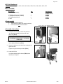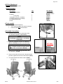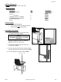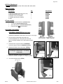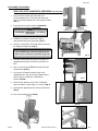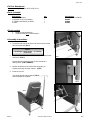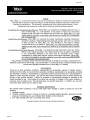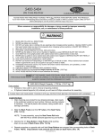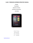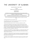
1
Page 1 of 8
IV - IV Pole Attachment
For Models:
2570, 2571, 2572, 2573, 2574, 2575, 5251,5261, 5271, 5281, 5291, 5351,
5361, 5400,5560,5570,5580,5670, 5680,5851,5861,6530,6531, 6540,
6541, 6550, 6551, 6560, 6570, 6571, 6700, 6710, 6740, 6750, 6940,
6950, 6980, 6990
CUSTOMER INSTRUCTIONS
PLEASE READ AND FAMILIARIZE YOURSELF WITH ALL INSTRUCTIONS BEFORE USING THIS PRODUCT.
If you have trouble understanding these instructions contact your dealer or Winco customer support, (800) 237-3377
before attempting to use this product; otherwise injury may occur.
Winco assumes no responsibility for damage or injury caused by improper assembly,
installation, use, or maintenance of these products.
TO REDUCE THE RISK OF INJURY TO PERSONS:
1. READ AND FOLLOW ALL DIRECTIONS.
2. DO NOT use the IV pole for pulling, moving, or holding the chair in place.
3. DO NOT use this attachment in any location or on products other than those listed in these
instructions.
4. DO NOT make any modifications to the bracket or pole.
5. IV Pole and included bracket are designed for hanging IV solutions ONLY.
6. Immediately remove from service; Any chair with mechanical or visible damage.
7. USE ONLY WINCO AUTHORIZED REPLACEMENT PARTS.
8. SAVE THESE INSTRUCTIONS for future reference and training.
5516 Southwest 1st Lane
Ocala, FL 34474
1-800-237-3377 / 352-854-2929 / Fax: 352-854-9544
e-mail: [email protected]
Visit us on the web: www.wincomfg.com
PLEASE READ AND FAMILIARIZE YOURSELF WITH ALL INSTRUCTIONS BEFORE PROCEEDING WITH ASSEMBLY
006312
Revision F Date 10-22-13
JWC
Page 2 of 8
●IV Pole Attachment
Models: 5251, 5261, 5291, 5351, 5361, 5851, 5861, 6530, 6531, 6540, 6541, 6570, 6571
●Parts Included:
Description:
IV U-Bracket Assembly
Qty.
1
¼-20 Nylon Lock-nut (1-installed)
¾” Phillips-head Screw (installed)
2¾” Phillips-head Screw
IV Pole
3
1
2
1
Part Number
227600 (LEFT)
227605 (RIGHT)
566204
566504
566571
480500
●Tools needed:
·
·
·
Phillips Head Screwdriver
7/16” wrench (multiple size wrench included)
Powered tools NOT recommended –
Pictures shown with 227600A OPTION
●Assembly Instructions
1. Locate the rear-side of the chair and place the
“IV U-Bracket Assembly” onto the rear chair
frame rail. (FIG.1)
NOTE:
Left & Right is determined – as if sitting
in the chair
2. Next insert the (2) 2¾” screws into the holes provided
on the bracket assembly. (FIG.2)
3. Secure the bracket to the chair frame using the (2)
nylon lock-nuts.
FIG. 1
FIG. 2
FIG. 3
Tighten using the wrench provided. (FIG.3)
4. Insert the IV Pole.
Your chair should look like that of (FIG.4) when
assembly is complete.
FIG. 4
006312
Revision F Date 10-22-13
JWC
Page 3 of 8
●IV Pole Attachment
Models: 5271, 5281, 6550, 6551
●Parts Included:
Description:
IV U-Bracket Assembly
Qty.
1
IV Spacer
1” Grey Cap
¼-20 Nylon Lock-nut (1 installed)
¾” Phillips-head Screw (installed)
2¾” Phillips-head Screw
IV Pole
1
2
3
1
2
1
Part Number
227600 (LEFT)
227605 (RIGHT)
227607
700700
566204
566504
566571
480500
●Tools needed:
·
·
·
Phillips Head Screwdriver
7/16” wrench (multiple size wrench included)
Powered tools NOT recommended –
●Assembly Instructions
1. Locate the proper location on the chair for the
“IV U-Bracket Assembly”. (FIG.1 & 1A)
NOTE:
Left & Right is determined – as if sitting
in the chair
FIG. 1
FIG. 2
FIG. 2A
2. Insert the “IV Spacer” into the “IV U-Bracket”
(FIG. 2 or FIG.2A) and place onto chair frame.
527 ONLY
IMPORTANT:
527 “IV Spacer” should be placed towards
the top of the “IV U-bracket”. (FIG.2A)
3. Insert the two screws through the holes in the
“IV U-Bracket”. (FIG.2B)
4. Screw on the nylon lock-nuts and, using the wrench
provided, tighten the lock-nuts to the bracket. (FIG.3)
FIG. 3
5. Your chair should look similar to that of (FIG.4)
FIG. 4
006312
Revision F Date 10-22-13
JWC
Page 4 of 8
●IV Pole Attachment
Models: 2570, 2571, 2572, 2573, 2574, 2575
●Parts Included:
Description:
IV U-Bracket Assembly
Qty.
1
IV Spacer
1” Grey Cap
¼-20 Nylon Lock-nut (1 installed)
¾” Phillips-head Screw (installed)
2¾” Phillips-head Screw
IV Pole
1
2
3
1
2
1
Part Number
227600 (RIGHT)
227605 (LEFT)
227607
700700
566204
566504
566571
480500
●Tools needed:
·
·
·
Phillips Head Screwdriver
7/16” wrench (multiple size wrench included)
Powered tools NOT recommended –
FIG. 2
●Assembly Instructions
6. Locate the proper location on the chair for the
“IV U-Bracket Assembly”. (FIG.1)
NOTE:
Left & Right is determined – as if sitting
in the chair
7. Insert the “IV Spacer” into the “IV U-Bracket”
(FIG.2) and place onto chair frame.
FIG. 1
8. Insert the two screws through the holes in the
“IV U-Bracket”. (FIG.3)
9. Screw on the nylon lock-nuts and, using the wrench
provided, tighten the lock-nuts to the bracket. (FIG.3)
10. Your chair should look similar to that of (FIG.4)
FIG. 3
FIG. 4
006312
Revision F Date 10-22-13
JWC
Page 5 of 8
●IV Pole Attachment
Models: 5560, 5680, 6560, 6740, 6750, 6940, 6950, 6980, 6990
●Parts Included:
Description:
Qty.
Part Number
IV Bracket Assembly (5560, 6560, 6940, 6950)
IV Bracket Assembly (6980, 6990)
¼-20 Nylon Lock-nut (installed)
¾” Phillips-head Screw (installed)
IV Pole
1
1
1
1
1
227610
227610B
566204
566504
480500
●Tools needed:
·
·
·
·
Phillips Head Screwdriver (5560/6560 ONLY)
½” Wrench (6940/6950/6980/6990 ONLY)
3/16” Allen Wrench (6940/6950/6980/6990 ONLY)
Powered tools NOT recommended –
FIG. 1
●Assembly Instructions
5560/6560 & 6980/6990 (Right Side ONLY)
(6940/6950 & 6980/6990 Left Side ONLY instructions on next page)
1. First, check the bracket that came with your
IV Pole Attachment Kit. Verify that the screw and
lock-nut, already installed, are in their proper location.
(FIG. 1
2. Locate the left or right rear side for 5560/6560.
Locate the right-rear side for 6980/6990. (FIG.2)
3. Unscrew the bolts in the cross brace. (FIG.2A)
NOTE:
Left & Right is determined – as if sitting
in the chair
4. Place the “IV Bracket” over the cross brace,
reinsert the screws, and tighten to a snug fit. (FIG.3)
FIG. 2
FIG. 2A
5. Your chair should look like (FIG.4).
FIG. 4
FIG. 3
006312
Revision F Date 10-22-13
JWC
Page 6 of 8
●Assembly Instructions
5680, 6740, 6750, 6940/6950 & [6980/6990 (Left Side Only)]
FIG. 1
1. First, check the bracket that came with your
IV Pole Attachment Kit. Verify that the screw and
lock-nut, already installed, are in their proper location.
(FIG. 1)
2. Locate the left or right rear side for 6940/6950.
Locate the left rear side for 6980/6990.
NOTE:
Left & Right is determined – as if sitting
in the chair
3. CAREFULLY place the chair on it’s side &
And open the swing arm all the way. (FIG.2)
4. Using a ½” wrench & a 3/16” allen wrench unscrew
the swing-arm hinge bolt. (FIG.3)
NOTE:
Some FORCE may need to be applied to the
allen wrench in order to loosen the hinge bolt
FIG. 2
5. Take the loosened bolt out of the arm bracket, lift
upholstered swing-arm off of frame, and place on
floor.
6. Use a ½” wrench and REMOVE the bolts from the
hinge bracket. (FIG.4)
7. Line up the “IV Bracket” with the holes in the
upholstered arm. Be sure the pre-installed screw
and nut on the “IV Bracket” is towards the
bottom. (FIG.4A)
FIG. 3
8. Place the arm bracket on top of the “IV Bracket”
and re-install the 2 bolts using a ½” wrench. (FIG.4)
9. Re-install the upholstered arm onto the chair frame
(FIG.5)
10. Your chair should look like (FIG.6)
FIG. 4
FIG. 4A
FIG. 6
006312
Revision F Date 10-22-13
FIG. 5
JWC
Page 7 of 8
●IV Pole Attachment
Models: 5400, 5570, 5580, 5670, 6700, 6710
●Parts Included:
Description:
IV Bracket Assembly
¼-20 Nylon Lock-nut (installed)
¾” Phillips-head Screw (installed)
IV Pole
Qty.
1
1
1
1
Part Number
227630 (LEFT or RIGHT)
566204
566504
480500
●Tools needed:
·
·
Phillips Head Screwdriver
Powered tools NOT recommended –
●Assembly Instructions
1. Locate the rear-side of the chair and remove the 2 screws
from the rear-brace (FIG.1)
NOTE:
Left & Right is determined – as if sitting
in the chair
2. Next, line up the holes in the IV bracket with the holes in the
rear-brace. (FIG.2)
FIG. 1
Nut and bolt pre-installed on the IV tube should be in
down position. (FIG.2-ARROW)
3. Secure the bracket to the chair frame using the (2)
screws previously removed in step 1. (FIG.3)
5. Insert the IV Pole.
Your chair should look like that of (FIG.4)
when assembly is complete.
FIG. 2
FIG. 4
FIG. 3
006312
Revision F Date 10-22-13
JWC
Page 8 of 8
006312
Revision F Date 10-22-13
JWC