1
Consolidated Chassis Management LLC (CCM)
Maintenance & Repair Procedures Manual
Version 4.1
Effective Date: June 1, 2013
CCM M&R Procedures Manual
Version 4.1 June 1, 2013
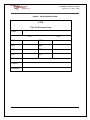
Table of Contents
Topic
Pages
Section 1 – Introduction
CCM Systematic Maintenance Program
Section 2 - Identifying need of repair
Section 3 – Repair Criteria:
Table A – Structural Criteria (Excluding Legs)
Table B – Structural Criteria (Legs)
Table C – Securing Devices
Table D – Sliding Assembly
Table E – Brake Systems
Table F – Electrical
Table G – Tires
Table H – Wheel Group
Table I – Suspension
Table J – Miscellaneous
Section 4 – Chassis Induction (COOP)
Section 5 – Chassis Removal (DECOOP)
Section 6 – Tires
Tire Specifications – Recaps
Tire Specifications – OEM
Tube Handling & Inspection
Tire Airing
Replacement Program
Section 7 – Auto Approvals
Section 8 – Damage Recovery
Section 9 – Wheel End M&R Procedure
Section 10 – Various M&R Polices
Section 11 – CCM Audit Safety Checks
Section 12 – M&R Vendor Self-Audit Process
Section 13 – Tire Safety
Section 14 – Used Rim Inspection Process
Section 15 – DVER Receipt Procedure
Section 16 – DVIR Procedure for Clearing
Annual Vehicle Inspection Certification Form
Brake Inspector Certification Form
Acknowledgement
Page 2 of 54
3
3–4
4–6
7 – 11
12 – 13
14
15
16 – 20
21 – 22
22 – 24
25
26 – 27
28
29 – 30
31
31 – 32
32 – 33
34
34 – 36
37 – 38
38
39 – 40
41 – 43
43 – 44
44
45
46
46 – 47
47 – 49
49 – 51
52
53
54
CCM M&R Procedures Manual
Version 4.1 June 1, 2013
Section 1- Introduction
1.0
Purpose of Manual
This manual is to be used in conjunction with the current edition IICL Guide for Container
Chassis Inspection and Maintenance Fourth Edition (IICL Chassis Guide) to ensure that all
equipment managed by Consolidated Chassis Management (CCM) is maintained in a safe,
operable manner, and in full compliance with FMCSA standards. It is the purpose of this manual
to provide guidance to CCM staff and M&R vendors, on the policies and procedures for
repairing and maintaining CCM managed equipment.
1.1
Safety
CCM is dedicated to the safety of its employees, representatives, suppliers, contractors and the
general public. It is our objective to ensure that all equipment is repaired and operated in the
safest manner possible.
To that end, CCM requires that all parties repairing or causing CCM equipment to be repaired, ensure
that all Occupational Safety and Health Administration (OSHA) and state safety requirements and
procedures be observed at all times while inspecting and/or repairing equipment.
1.2 CCM SYSTEMATIC MAINTENANCE PROCEDURE
The following procedures are to be followed by CCM staff and M&R vendors to ensure that CCM
managed chassis are systematically inspected and repaired as necessary to ensure compliance with
applicable FMCSA (49 CFR 393 – 396) regulations. The associated records of all inspections and repairs
of the chassis must be retained and communicated to CCM.
M&R VENDORS
Whenever a chassis is repaired, with the exception of chassis tires only or a chassis being repaired
through a roadability lane, the M&R vendor must complete a Systematic Maintenance Check (“SMC”) to
visually inspect the entire chassis for any roadability defects. The inspector will either certify that the
chassis does not need any additional repairs, or will identify items that require further repair as guided
by the nine component categories below.
1.
2.
3.
4.
Brakes, and all components thereof
Lights - Lighting devices, lamps , markers, and conspicuity marking material
Wheel - Wheels, rims, lugs, tires
Air Line - Air line connections, hoses, and couplers
Page 3 of 54
CCM M&R Procedures Manual
Version 4.1 June 1, 2013
5.
6.
7.
8.
9.
Coupling - King pin upper coupling device
Frame - Rails or support frames
Bolster - Tie down/bolsters front and rear
Fastener - Locking pins, twist locks, clevises, clamps, or hooks
Slider - Sliders or sliding frame lock
Once the SMC is completed and all identified defects, if any, have been repaired, the SMC shall be
recorded in the CCM M&R system. By entering the SMC in chassis.com, the vendor is certifying that the
chassis meets all FMCSA roadability criteria.
It is incumbent upon the M&R vendors to develop and implement a quality program to ensure that the
SMC is performed and all CCM M&R policies and procedures are complied with.
CCM POOL MANAGEMENT
The CCM Pool Manager will audit the repair and inspection records to ensure the SMC is recorded with
the repair invoice in the CCM M&R system. The Pool Manager will address repairs invoiced without an
SMC with the M&R vendor. This procedure will ensure inspections are properly performed and reported
by the M&R vendor.
CCM, or its agents, will conduct field audits of the CCM M&R vendor’s compliance with this procedure.
Each month, the Pool Manager will identify all active chassis in the pool that have not had an SMC
reported within the last 6 months. The Pool Manager will locate these chassis and after placing a hold
on the chassis arrange for an inspection to be performed.
Section 2 – Identifying the Need for Repair
2.0
General Inspection Requirements
While the SMC is an essential part of the safe operation of an intermodal chassis, valuable input must
also be provided by the driver operating the equipment over the road. Problems appearing from wear,
in coupling as well as suspension, tracking, and brakes can often be more readily identified by the driver,
therefore, input from the driver is considered essential and must be recorded and fully investigated
whenever such a report is provided through a Driver Vehicle Inspection Report (DVIR). Please see the
DVIR and DVER procedures that are included in this manual.
2.1
Inspection Criteria
All equipment is to be inspected in accordance with applicable U.S. Federal regulations governing
chassis including but not limited to 49 CFR 390-396, 571.108 and 571.121. Repairs are to be to IICL
Page 4 of 54
CCM M&R Procedures Manual
Version 4.1 June 1, 2013
standards for chassis. For a more detailed description of these regulations please refer to the IICL
Chassis Guide section 1.3 in its entirety. Inspectors and their employers should also be aware of the
latest version of the criteria for “Out Of Service” (OOS) as provided by the Commercial Vehicle Safety
Alliance (CVSA) and enforced by state police agencies.
This guide provides suggested criteria for determining what is a repairable and the preferred methods
and extent of repair. It should always be remembered, however, that the overriding consideration in all
inspections and repair operations is the ensured safe operation of the chassis.
2.2
Determining Repair Worthiness
Any defect, whether caused by damage or wear is to be repaired if it affects the safe operation of the
unit. In some occasions of major damage the repairs may be suspended pending the possible scrapping
or termination of the chassis.
2.3
Definitions of Wear & Damage
Wear damage is one or more defects caused by continuous deterioration in the physical
condition of the chassis resulting from normal use. For examples of wear please refer to the IICL
Chassis Guide Section 4.
2.4
Chassis Repair Criteria
The following tables contain a list of components and corrective actions taken. The components are
classified as follows:
Table A – Structure
Table B – Landing Gear
Table C – Securing Devices
Table D – Slider Assemblies
Table E – Brake System
Table F – Electrical System
Table G – Tires
Table H – Wheel Group
Table I – Suspension
Table J – Miscellaneous
NOTE: Items which are required in accordance with FMCSA 49 CFR 393 & 396 and Appendix G to 49
CFR, Chapter III, Subchapter B are indicated in the table with “*”
Page 5 of 54
CCM M&R Procedures Manual
Version 4.1 June 1, 2013
Also note that while these criteria are largely similar to the IICL Chassis guide, there are some
differences with regard to nonstructural high frequency repair items. All criteria are based on the
premise that all equipment should be inspected and maintained to FMCSA Standards and repairs made
to the standards contained in the current edition of the IICL Container Chassis Manual.
Page 6 of 54
CCM M&R Procedures Manual
Version 4.1 June 1, 2013
Table A
Structure Criteria (excluding landing gear)
Component
Condition
Action Required
* Missing / loose components / fasteners
Repair/replace
*Cracked, broken, loose, fastenings
Repair/replace
*Any condition, loaded or empty, that causes frame or
body to be in contact with any moving component
Repair/replace as necessary after determination of cause
Cracked/ chipped / distorted. Any movement in any
direction; distortion / unusual wear that affects operation
Replace
Worn Beyond Wear Limits
Replace
Broken welds or cuts
Repair
Cut/torn/cracked components
Repair/replace
Uneven wear/dished/bulged/or distorted upwards
If power unit fifth wheel cannot engage kingpin, Repair/replace
Blockage of drain holes
Unblock
Severe corrosion
Repair/replace
All mainframe
components, including
crossmembers
Kingpin
Upper Coupler
* Items included in inspection requirements of U.S. FMCSA 49 CFR 393 and396, Appendix G to 49 CFR , Chapter III and Subchapter B
Page 7 of 54
CCM M&R Procedures Manual
Version 4.1 June 1, 2013
Table A
Structure Criteria (excluding landing gear) (Cont.)
Component
Condition
Main rails - main rail
gussets
Bolsters
Action Required
Any deformation such as a bends, bows, dents, etc.
If damage prevents a container from properly securing to the
chassis, would cause damage to the container if left unrepaired,
or prevents the chassis from tracking properly, repair/replace
Cracked/broken welds
Reweld
Cut or torn Component
If damage prevents a container from properly securing to the
chassis, would cause damage to the container if left unrepaired,
or prevents the chassis from tracking properly, repair/replace
Elongation of hole in web for passage of landing leg shaft
If elongated to more than 5in. (125mm) in diameter or within 1"
(25mm) of main rail flange, repair
Cracked or broken welds
Repair
Cut or Torn Component
Repair
Any deformation such as a bends, bows, dents, etc.
If container cannot be secured to the chassis, Repair
Severe Corrosion
Repair
* Items included in inspection requirements of U.S. FMCSA 49 CFR 393 and396, Appendix G to 49 CFR , Chapter III and Subchapter B
Page 8 of 54
CCM M&R Procedures Manual
Version 4.1 June 1, 2013
Table A
Structure Criteria (excluding landing gear) (Cont.)
Component
Condition
Action Required
If cracks exceed 20% of total weld area or it is felt that
component will come off during use, reweld
Cracked/broken welds
Cut or torn Component
If damage prevents a container from properly securing to the
chassis, or would cause damage to the container if left
unrepaired, Repair/replace
Any deformation such as a bends, bows, dents, etc.
If damage prevents a container from properly securing to the
chassis, or would cause damage to the container if left
unrepaired, Repair/replace
Cut or torn
Cuts in upper or lower flange that would contact the container
and cause damage or extend into the vertical plane of the
crossmember, repair/replace
*Cracked/broken welds in upper or lower flange at main
rail or gusset
Repair only in conjunction with FMCSA/FHWA inspection
*cracked/broken welds in the radius or the vertical plane
of any crossmember
Repair
Bolster gussets
Crossmember
* Items included in inspection requirements of U.S. FMCSA 49 CFR 393 and396, Appendix G to 49 CFR, Chapter III and Subchapter B
Page 9 of 54
CCM M&R Procedures Manual
Version 4.1 June 1, 2013
Table A
Structure Criteria (excluding landing gear) (Cont.)
Component
Condition
Any deformation such as a bends, bows, dents, etc.
Action Required
If damage prevents a container from properly securing to the
chassis, would cause damage to the container if left unrepaired,
or disturbs the vertical welds to the main Repair/replace
Severe Corrosion
Repair/replace
Cut Component,
Cuts in upper or lower flange that would contact the container
and cause damage repair/replace
Crossmember (cont’d)
If cracks exceed 20% of total weld area or it is felt that
component will come off during use, reweld. Minor cracks
between crossmember and gusset upper flange are to be repaired
only in conjunction with FMCSA/FHWA Inspection.
Crossmember gussets
Cracked, Broken welds
Under-ride Protection
("ICC bumper")
Cut component, cracked/broken welds
Repair
Missing(if provided originally) or partially removed
Repair/Replace
Any deformation such as a bends, bows, dents, etc.
Deformed over 2.0 in. (50mm) outside rear plane of unit OR if not
within 22in. (560mm) of road service, OR if touching springs/
tires/ any moving component under any condition including
loading - repair/replace OR bent inward where vehicle behind
cannot see the conspicuity markings
* Items included in inspection requirements of U.S. FMCSA 49 CFR 393 and396, Appendix G to 49 CFR, Chapter III and Subchapter B
Page 10 of 54
CCM M&R Procedures Manual
Version 4.1 June 1, 2013
Table A
Structure Criteria (excluding landing gear) (Cont.)
Component
Condition
Action Required
Torn/cracked/severe corrosion
Repair/replace
Loose
Resecure
Bent
If affecting the visibility of the lighting OR the securing of the
lighting OR if touching tires or any other moving component
under any condition including loading, repair
Cut or torn
If cut 3 inches horizontally at the mount bracket - replace
Holed
If hole is more than 2in. (50mm) in diameter, replace
Loose or missing fasteners
If more than one fastener missing, repair/replace
Improper length
Repair/replace
Cut or torn
If it can no longer properly secure with mud flap without
damaging it, repair/replace
Cracker or broken welds
Repair
Any deformation such as a bends, bows, dents, etc.
If deformation causes the mud flap or brackets to touch the tires,
or ground, repair/replace
Missing(if provided originally) or partially removed
No action
Light Box
Mud flaps
Mud flap Bracket
Dock bumpers
* Items included in inspection requirements of U.S. FMCSA 49 CFR 393 and396, Appendix G to 49 CFR, Chapter III and Subchapter B
Page 11 of 54
CCM M&R Procedures Manual
Version 4.1 June 1, 2013
Table B
Landing Leg Criteria
Component
Condition
Action Required
Missing or loose parts or fasteners
Repair/replace
Holed, cut, or torn
Replace
Cracked/broken weld
Repair/replace
All landing gear
Components
NOTE: Landing leg upper tube can be re-welded to the landing gear mounting plate provided there is no distortion to the leg tube.
Any deformation such as a bends, bows, dents, etc.
If deformation causes toeing of legs in any direction, or impairs
operation of legs, Replace with 3 inch “C” channel
Cracked/kinked
Repair/replace
Uneven height
Repair
out of alignment
Repair
Any deformation such as a bends, bows, dents, etc.
If operation is impaired, repair/replace
Gearbox
Inoperable in one and or both gears
Repair/replace
Cross shaft
Any deformation such as a bends, bows, dents, etc.
If operation is impaired, repair/replace
Landing leg brace
(diagonal or cross brace)
Landing legs
* Items included in inspection requirements of U.S. FMCSA 49 CFR 393 and396, Appendix G to 49 CFR, Chapter III and Subchapter B
Page 12 of 54
CCM M&R Procedures Manual
Version 4.1 June 1, 2013
Table B
Landing Leg Criteria (Cont.)
Component
Condition
Action Required
Crank handle
Any deformation such as a bends, bows, dents, etc.
If handle cannot be secured to chassis or leg brace OR if the
handle is too short to operate landing gear when container is
mounted, replace
Crank handle retainer
Any deformation such as a bends, bows, dents, etc.
If inoperable or missing, repair/replace
Any deformation such as a bends, bows, dents, etc.
If shoe(or wheel) does not rest firmly on the ground when
landing gear is extended and it does not fully support the chassis,
repair/replace
Axle openings elongated or torn
If the hole is enlarged or otherwise distorted where there is risk
if the shoe falling off, replace
Seized/Ability of the sand shoe to swivel is impaired
If shoe(or wheel) does not rest firmly on the ground when
landing gear is extended and it does not fully support the chassis,
repair/replace
Sand shoes/sand
pads/wheels
Sand Shoe Axle
* Items included in inspection requirements of U.S. FMCSA 49 CFR 393 and396, Appendix G to 49 CFR, Chapter III and Subchapter B
Page 13 of 54
CCM M&R Procedures Manual
Version 4.1 June 1, 2013
Table C
Securing Device Criteria
Component
Condition
Action Required
*Missing component, handles, or retainers
Replace
*Unattached, inoperable or incapable of secure
attachment
Repair
*Cracked or broken components or welds
Repair
*Seized or frozen
Repair
Any deformation such as a bends, bows, dents, etc.
If securement operation is impaired, replace
Loose fasteners
*Bent handles which are not operable and/or protrude
beyond the envelope of chassis when in locked position
Repair
*Any vertical movement of twist locks greater than one (1)
inch.
Repair
*Any horizontal movement of twist lock greater than ½
inch from the 90 degree angle when locked
Repair
Securing devices (safety
devices), including twist
locks, locking pins, twist
lock collars, springs, twist
lock handles and handle
retainers(ALL locking
devices must be
operable)retainers or
springs
Repair
* Items included in inspection requirements of U.S. FMCSA 49 CFR 393 and396, Appendix G to 49 CFR, Chapter III and Subchapter B
Page 14 of 54
CCM M&R Procedures Manual
Version 4.1 June 1, 2013
Table D
Slider Assembly Criteria
Component
Adjustable Axle
Assemblies(sliding sub
frames or sliding tandems)
- all components
Condition
Action Required
*Missing, unengaged or loose parts or fasteners, including
lock pins
Repair/replace
*Cut/torn/cracked/broken
Repair
Any deformation such as a bends, bows, dents, etc.
If slider operation or securement is impaired, repair
*Cracked, chipped, or broken
Repair
Any deformation such as a bends, bows, dents, etc.
If pins do not engage index holes and a minimum of .25in.(6mm)
exclusive of chamfered edge of pin, past face of rails after
engagement, repair
Elongation
If more than .125in. (3mm) in longitudinal travel, repair
Cracked or deformed around perimeter of hole
Repair
Cracked, broken, distorted, worn-out
Repair/replace
cracked or broken weld
Repair
*Missing or cannot be engaged
Repair/replace
*Unattached or incapable of attachment
Replace
Slider frame
Locking(indexing) pins
Indexing Holes
Stops
Safety Devices, including
lock pins, indexing holes
and stops
NOTE: Extendable chassis of adjustable length and or with sliding axle assemblies should be carefully inspected to ensure that the mechanism is in proper
working order, that all locking pins are properly engaged and that the flexible airlines and electrical harnesses are properly routed and secured to prevent
chaffing , regardless of load before, during or after adjustment of chassis length
* Items included in inspection requirements of U.S. FMCSA 49 CFR 393 and396, Appendix G to 49 CFR, Chapter III and Subchapter B
Page 15 of 54
CCM M&R Procedures Manual
Version 4.1 June 1, 2013
Table E
Brake System Criteria
Component
Condition
Action Required
Service brakes
*Absence of braking action on any axle required to have
brakes upon application of service brakes
Determine cause and repair/replace components as required to
achieve proper braking action
* Missing Brake
Replace
*Absence of braking action on vehicle or combination
upon actuation of parking brake control, (including
driveline hand controlled parking brakes)
Determine cause and repair/replace components as required to
achieve proper braking action
Parking Brake
All mechanical brake
system components,
including shoes, return
springs, anchor pins,
spiders, cam shafts and
bushing, rollers, pushrods,
air chambers, and all
mounting or support
brackets and fasteners
Missing, loose, bent, broken, frozen
Repair/replace
* Items included in inspection requirements of U.S. FMCSA 49 CFR 393 and396, Appendix G to 49 CFR, Chapter III and Subchapter B
Page 16 of 54
CCM M&R Procedures Manual
Version 4.1 June 1, 2013
Table E
Brake System Criteria (Cont.)
Component
Condition
Action Required
Cracked broken or leaking
Repair replace
Twisted, turned or loose
If not in vertical position repair
Clogged leaking or nonfunctional
Repair replace
Any audible leak
Repair/replace
Cracked or damaged by heat
Replace
Missing
Replace
Cut, torn, cracked, burned, folded
If leaking, replace
Missing, loose, bent, broken, frozen
Replace
*ABS malfunction indicator lamp remaining lit more than 5
seconds, or illuminated at any time while chassis is moving
at road speed
Repair
*ABS malfunction indicator lamp does not operate during
a bulb check; bulb or lens broken
Repair
* Crimped collapsed or broken
Repair/replace
Cut or torn
Repair/replace
Clogged , leaking or otherwise non functional
Repair/replace
* Any audible leak
Repair/replace
*Cracked or heat damaged
Repair/replace
Glad-hands
Glad-hand gaskets
Antilock brake systems
Air Line Tubing
* Items included in inspection requirements of U.S. FMCSA 49 CFR 393 and396, Appendix G to 49 CFR, Chapter III and Subchapter B
Page 17 of 54
CCM M&R Procedures Manual
Version 4.1 June 1, 2013
Table E
Brake System Criteria (Cont.)
Component
Condition
Action Required
Crimped
Repair replace
Cut or torn
Repair/replace
Obstructed, leaking or otherwise nonfunctional
Repair/replace
* Cracked, crimped or broken
Repair/replace
* Abraded/chafed through outer reinforcement ply
Repair/replace
* any bubbling or swelling when charged with air
Repair/replace
* Any audible leak
Repair/replace
* Improper connections or previous repairs (use of screw
type hose clamps not permitted)
Repair/replace
* Improperly routed/secured, touching axles or other
moving components when chassis is laden or empty
Repair/replace
Cracked or broken
Repair/replace
Obstructed, leaking or otherwise nonfunctional
Repair/replace
Puncture of any type (cut, tear etc.)
Replace
air leaks at fittings
Repair/replace
Broken/cracked mounts
Repair
Loose/missing fasteners
Repair/replace
Air hoses
Relay Valve
Air Tank(s)
* Items included in inspection requirements of U.S. FMCSA 49 CFR 393 and396, Appendix G to 49 CFR, Chapter III and Subchapter B
Page 18 of 54
CCM M&R Procedures Manual
Version 4.1 June 1, 2013
Table E
Brake System Criteria (Cont.)
Component
Condition
Action Required
* Inoperable
Replace
* Any audible air leakage
Replace
Severe Corrosion
Replace
Air/spring brake chamber
NOTE: Appropriate caution must be observed at all times in the inspection and handling and replacement of spring brake chambers. Under no
circumstances should an attempt be made to open a spring brake chamber during inspection
Component
Slack Adjusters
Brake linings/pads and
shoes (See note below
regarding applicable U.S.
Fed Regs)
Condition
*Cracked, broken, stripped, or otherwise nonfunctional or
mismatched (auto slack combined with manual on same
axle) See notes below
Seized or stiff
Action Required
*Excessive or uneven wear
.25in.(6mm) or less pad/lining thickness at shoe center, replace
Cracked/chipped through the thickness of the pad/lining
at the shoe edge
Replace
Cracked/chipped/broken parallel to the shoe edge
If the crack is more than .0625in. (1.6mm) wide OR more than
1.5in. (38mm) long - replace
* Lining/pad loose rivets broken/missing
Replace
Repair/replace
Repair/replace
NOTE: Chassis manufactured after October 20, 1994 must have automatic slack adjusters in all braking positions.
NOTE 2: Manual and/or automatic slacks cannot be mixed on the same axle. If chassis is manufactured after October 20, 1994, slacks must be
automatic.
* Items included in inspection requirements of U.S. FMCSA 49 CFR 393 and396, Appendix G to 49 CFR, Chapter III and Subchapter B
Page 19 of 54
CCM M&R Procedures Manual
Version 4.1 June 1, 2013
Table E
Brake System Criteria (Cont.)
Component
Condition
Action Required
* Saturated with oil or grease or otherwise
contaminated/glazed
Replace
Brake linings/pads and
shoes (See note below
regarding applicable U.S.
Fed Regs.) (Cont.)
If more than .0625in (1.6mm) replace
If the crack extends across the face or through the thickness of
the lining, replace
th
If the crack or void exceeds 1/16 in width OR exceeds 1.5 in. in
length, replace
*Lining separated from the shoe
*Lining has vertical cracks
*Lining has horizontal cracks
Brake drums
Brake Adjustment
* Cracks on the outer surface that open on application of
the brakes
Replace
* Deep scoring (NOT hairline heat checking)
Replace
* Any missing sections or in danger of coming off
Replace
* Any single past the brake readjustment limit by
.25in.(6mm) or more
Repair in accordance with the USDOT Readjustment limits
* Any two brakes on the same chassis that exceed the
readjustment limit by any amount
NOTE: Please refer to IICL Chassis Guide Appendix A, Tables 1, 2, and 3 for more detailed information on US Fed. Requirements regarding brake
readjustment and maximum allowable stroke. Stroke is to be measured with power unit engine off and air tank/reservoir pressure of 90PSI with the brakes
fully applied. BRAKE REPAIRS ARE TO BE PERFORMED ONLY BY QUALIFIED MECHANICS.
* Items included in inspection requirements of U.S. FMCSA 49 CFR 393 and396, Appendix G to 49 CFR, Chapter III and Subchapter B
Page 20 of 54
CCM M&R Procedures Manual
Version 4.1 June 1, 2013
Electrical System
Table F
Component
Condition
Missing/loose parts or securements
Action Required
Repair/replace
Bent/distorted/missing pins
If not making good secure connection with plug or not providing
sufficient contact, repair/replace
Broken pins /insulation
Repair/replace
Intermittent/no/faulty ground
Repair/replace
Corroded
Clean/replace
exposed wiring/connections
Repair/replace
*missing, burned out broken
Repair/replace
*Insufficient illumination
Repair/replace
Clearance /marker/
Identification/
stop/turning/running
license plate light
assemblies
*Missing or inoperable
Repair/replace
Accumulating moisture
If damage affects the ability of the component to secure the lens
and bulb or the securement of the assembly to the chassis,
repair/replace
Repair/replace
Reflectors
*Broken/chipped, cracked through, missing or broken
Repair/replace
Short Circuit
Repair
Bare cut or frayed insulation
If bare wire is exposed - repair
Dangling loose
Resecure/repair
Receptacle (7way plug)
Clearance/ marker/
Identification/
stop/turning/running
license plate light bulbs
and lens
Wiring
*broken or cracked
* Items included in inspection requirements of U.S. FMCSA 49 CFR 393 and396, Appendix G to 49 CFR, Chapter III and Subchapter B
Page 21 of 54
CCM M&R Procedures Manual
Version 4.1 June 1, 2013
Table F
Electrical System (Cont.)
Component
Condition
Action Required
All lighting equipment and
reflectors as required in
49 CFR 393 or FMVSS108
* Inoperable for any reason or missing
Repair/replace
Note: detail listing of lighting requirements provided in IICL Chassis guide Appendix B
Table G
Tire Criteria
Component
Condition
Action Required
* Audible or manual detection of air leak OR tire is
received with less than 65 psi air pressure
Repair/replace
*Belt or body ply material is visible through tread or
sidewall
Replace
* Tread depth is 2/32nds in. (2mm) or less at any point
measured in a major tread grove
Replace
* Any tread or sidewall penetration that when probed
indicates penetration of belt or cord
Replace
* Any cut on sidewall or in the tread where the body or
belt cord material has been cut, exposed or penetrated
Replace
Visible blisters or knots
Replace
Severe weather checking if more than .25in.(6mm) deep
Replace
Tires
* Items included in inspection requirements of U.S. FMCSA 49 CFR 393 and396, Appendix G to 49 CFR, Chapter III and Subchapter B
Page 22 of 54
CCM M&R Procedures Manual
Version 4.1 June 1, 2013
Table G
Tire Criteria (cont.)
Component
Condition
Action Required
Blown out or Impact break
Replace
Missing
Replace
Flat/Slid flat tires
If lowest point of the tire measures 2/32in.(2mm) or less replace
Adjacent tires with a mismatch in height of more than 3/8
inch
Exchange or replace tires to match heights of tires
Abnormal/uneven wear
If lowest spot on the tire as measured in a major tread is
2/32in.(2mm) or less replace NOTE: Regardless of variance in
tread depth, chassis suspension and alignment should be
checked for defects
Contact of adjacent tires (Kissing)
Determine cause and repair/replace as necessary
Incompatible tires (mixing radial and bias tires on same
axle)
Exchange or replace tires to mate correct types of tires
Tire contacts the container or any other part of the chassis
or the container when loaded or empty
Research cause and repair/replace as necessary
Over/under inflated per stated specification
Adjust air pressure as appropriate to achieve uniform 90 PSI
Tires not marked for multi position or trailer use only
Replace
Tires (Cont.)
* Items included in inspection requirements of U.S. FMCSA 49 CFR 393 and396, Appendix G to 49 CFR, Chapter III and Subchapter B
Page 23 of 54
CCM M&R Procedures Manual
Version 4.1 June 1, 2013
Table G
Tire Criteria (cont.)
Component
Condition
Action Required
Valve Stems
Pinched, cut, kinked, flattened, crushed where stem is
leaking air , impedes air flow, or will not seat a valve cap
Replace
Clogged/obstructed
Clean and install new valve cap
Missing or broken
Replace with pressure caps only
Improperly mated parts
* Cracked/broken
*Bent Flange away from bead more than 3/8”
*Bent Flange away from bead less than 3/8” in more than
two places
*Bent flange TOWARDS head regardless of depth
*Bent or deformation of web or base
*Improper seat or gap between lock ring and rim for the
circumference of the rim
*Any cracks to welds in rim or lock ring
*Lock ring gap exceeds ½”
Heavy rust, corrosion or pitting
Replace
Replace
Replace
Replace
Valve caps
Rims/rim base/Lock Rings
Rim spacer
Replace
Replace
Replace
Replace
Replace
Replace
Warped / distorted/ bent to expose bead, compromise the
seal, or integrity of the tire or present a hazard
Replace
Elongated bolt holes (Budd rims)
Any welded repairs on a rim or lock ring
Mismatched types
Valve stem locators worn to less than ¼ inch in height
Distorted or crushed
Replace
Replace
Replace as required
Replace
Replace
Improper tire clearance
replace
* Items included in inspection requirements of U.S. FMCSA 49 CFR 393 and396, Appendix G to 49 CFR, Chapter III and Subchapter B
Page 24 of 54
CCM M&R Procedures Manual
Version 4.1 June 1, 2013
Table H
Wheel Group Criteria
Component
Condition
* Cracked or broken
Action Required
Replace
* Elongated bolt holes
Replace
Broken/missing stripped, loose bent mismatched or
otherwise ineffectual
Replace
Cut/cracked/ broken
Replace
Leaking oil
Check gaskets and plug and repair/replace as necessary
Oil level low
Add as required and check for leaks
Low oil level
Add as required and check for leaks
Leaking inner seal
Evidence of fresh moist leakage, replace
Contaminated Oil
Drain all oil from hub, clean components as necessary and
replace
Cut/torn/ cracked/broken/warped
Replace
Leaking grease
Replace
Contaminated grease
Remove, clean & inspect bearing and hub, repair/replace as
necessary and repack
Cracked/pitted/worn/burned/scored
Replace
Wheels
Fasteners
Hubcaps (Oil Bath)
Inner hubs (oil bath)
Hubcaps (grease)
Bearings & Races
* Items included in inspection requirements of U.S. FMCSA 49 CFR 393 and396, Appendix G to 49 CFR, Chapter III and Subchapter B
Page 25 of 54
CCM M&R Procedures Manual
Version 4.1 June 1, 2013
Table I
Suspension Criteria
Component
Condition
Missing/ Loose components or fasteners
Action Required
Repair/replace
All Components
Welds cracked/broken
Cut/torn/cracked/broken/ inoperative
Heat Dots that turn black
Repair
Replace
Inspect and repair as required per CCM Heat Dot Procedure
Any visible bend/bow/dent/etc. affecting the operation or
alignment of the chassis
Replace/re-align
Worn Bushings
Replace
Adjustable Radius Rods
Stripped threads
Replace
Axles
Any visible bend/bow/dent/deformation affecting the
operation or alignment of the chassis
Repair/replace
Spindles bent/burned/ out of round (IPR)
Repair/replace
Distorted/worn out
Repair/replace
Broken/missing
Repair/replace
Inoperable
Repair/replace
Worn Bushings
replace bushings
Bends/bows/dents/ major deformities
If axle alignment or suspension operation is affected,
repair/replace
Radius Rods (All - fixed or
adjustable)
Springs
Spring Hangers &
Equalizers
* Items included in inspection requirements of U.S. FMCSA 49 CFR 393 and396, Appendix G to 49 CFR, Chapter III and Subchapter B
Page 26 of 54
CCM M&R Procedures Manual
Version 4.1 June 1, 2013
Table I
Suspension Criteria (Cont.)
Component
Condition
Action Required
Spring hangers and all
other axle positioning
components
* Cracked/bent/broken/missing/loose (possible cause of
axle shifting from set operating position
Repair/replace
Severe corrosion
Replace
*Any broken leaf (applies to all designs regardless of
amount of leaves included in assembly)
Replace
* Any missing leaf(multi-leaf units)
Replace
* Any leaves displaced or shifted that results in contact
with a tire, rim, wheel, brake drum or frame
Repair/replace
Seats & U bolts,
*Loose/ broken/ stripped/missing/cracked
Replace
Any component part of
the tracking/suspension
assembly or any
associated fasteners
* Cracked/broken/ loose/stripped or missing
Repair/replace
Leaf springs
NOTE: Whenever any work is done to the undercarriage of a chassis, check the torque of all fasteners. Use the decal that should be affixed to the side of
the chassis for correct torque. Also, check (and repair if necessary) the alignment after any work to spring hangers, springs, radius rods, etc. that could
affect the tracking of the chassis.
* Items included in inspection requirements of U.S. FMCSA 49 CFR 393 and396, Appendix G to 49 CFR, Chapter III and Subchapter B
Page 27 of 54
CCM M&R Procedures Manual
Version 4.1 June 1, 2013
Table J
Miscellaneous
Component
Condition
Action Required
* Cracks
Replace
* any previous welded repairs to the Pintle hook
* Pintle hook horn with a loss of 20% or more of original
thickness
* Latch Insecure
* Missing/stripped/improper fasteners
* Cracks on mounting surface extending from point of
attachment
* Loose mounting
Replace
Coupling Devices i.e.
frame crossmember
providing pintle hook
attachment
All Conspicuity Markings
are required by 49CFR393
or FMVSS 108
Owner's marks and ID
*Cracked
Replace
Broken Welds
Repair
*Missing, cut or damaged with more than 50% missing or
non-reflective. Missing at ICC Bumper horizontal bar.
Replace
worn/defaced/ missing/illegible
repair/replace
Foreign markings
If present
Remove
Holed/torn/missing/loose/Non watertight
Coupling Devices i.e.
pintle hook assembly
Coupling Devices i.e.
mounting of pintle hook
assembly to frame
Replace
Repair
Replace
Replace
Repair
Registration
Expired/illegible/missing invalid
repair/replace
If documents cannot be inserted or removed or will not allow the
cover to close securely and in a water tight fashion repair/replace
Contact owner for replacement
License plate mounting
loose missing improper securement
replace
License plate
Expired/missing/illegible/invalid
Contact owner for replacement
Registration Holder
Distorted/bent
* Items included in inspection requirements of U.S. FMCSA 49 CFR 393 and396, Appendix G to 49 CFR, Chapter III and Subchapter B
Page 28 of 54
CCM M&R Procedures Manual
Version 4.1 June 1, 2013
Section 4 – Chassis Induction Procedures
4.1
Chassis Induction Procedure
4.1.1 Chassis Induction Report (CIR) Requirement
All Chassis accepted into a Pool shall have a Chassis Induction Report (CIR) completed and filed with
CCM before the earlier of 120 days from the date of acceptance or the FMCSA expiration date. A copy
of the CIR can be found on CCM’s website, http://www.ccmpool.com. Copies of all CIRs will be
maintained by CCM for as long as a chassis is active in the pool.
4.1.2 Chassis Stencil
Once a successful CIR has been completed, Chassis will be stenciled in a contrasting color with letters
denoting the Pool designation (such as “GCCP”) measuring 4 inches in height on the side rails and 2
inches in height on the front and rear bolsters.
4.1.3 FMCSA Inspection
Chassis having an FMCSA inspection set to expire within 90 days of induction survey will require a full
FMCSA inspection in addition to the CIR.
4.1.4 FMCSA Expiration Date Stencil
All Chassis must have the FMCSA expiration date (month and year) stenciled on the front bolster, i.e.,
“FMCSA DUE 12 13” if space permits or “DUE 12 13” if not, using a contrasting 2” stencil.
4.1.5 CIR Verification
CCM may audit the vendor to verify that the CIR was performed, that all necessary repairs have been
made, and that the Chassis meets all requirements for Pool use.
4.2
Chassis Excluded from Pool
4.2.1 CIR or FMCSA Failed Inspection
A Chassis that fails a CIR or FMCSA inspection shall not be admitted into service until all defects are
repaired and the Chassis meets all Pool and FMCSA standards.
4.2.2 Unapproved Chassis Type
In the event that a vendor performs a CIR on a chassis type or specific unit not approved for use in the
Pool, the vendor will not be paid for such transaction. Any pool stencil applied mistakenly due to
completion of a CIR on a chassis type not approved for Pool use will be removed by painting over such
stencil with a matching paint color, at no cost to the pool. The Pool Manager shall delete said Chassis
from the fleet file and notify the Contributor to remove the Chassis.
Page 29 of 54
CCM M&R Procedures Manual
Version 4.1 June 1, 2013
4.2.3 Minimum Maintenance Acceptance Criteria for Chassis in Pool Operations
Chassis exhibiting any of the conditions listed below as discovered during the initial acceptance
inspection will not be accepted into the pool.
4.2.3.1 Corrosion
Any chassis with excessive corrosion/deterioration (rust through and/or rust jacking) to one or
more primary component. Primary components to include:
Bolsters
Main rails
Bogie rail
Coupler plate assembly
Suspension components
4.2.3.2 Design
Chassis with the following designs will not be allowed in the pool:
Chassis with Non west coast axle settings
Three or four hole hub cap axles
Old style suspensions with Cast hangers
Chassis with more than 3 leaf springs
Flush back, non-sliding 23 foot chassis
Chassis with worn brakes, regardless of type
Chassis with four single stage brake chambers (no spring brakes)
Chassis with Budd type wheels
Forty foot chassis with main rails of less than 12 inches in height
20 Foot chassis with main rails of 10 inches high or less
Chassis with gooseneck rails exceeding six inches in height
Open faced or “C” channel front bolsters
Chassis with small capacity single tank brake system
Chassis with square axles and/or screw on type hubcaps
4.2.3.3 Other Considerations
Chassis with other design and / or manufacturing defects as may
be determined
Chassis with major damages not deemed economically feasible to
repair
Total Loss chassis
4.3
Chassis moving between pools
If a member is moving a chassis between CCM operated pools (i.e. from SACP to MCCP), cooping into
the new pool requires only a CIR, inspection and replacing stenciling on the chassis to the new pool.
Page 30 of 54
CCM M&R Procedures Manual
Version 4.1 June 1, 2013
Section 5 – Chassis Removal Procedure (Decooping)
Termination or Move to another Pool
CCM will authorize a survey to be performed on each unit to determine the condition of the unit. CCM
will:
Require a CIR be completed detailing the condition of the chassis at the time of
decooping.
Authorize repairs of DAMAGED components required to bring the chassis to FMCSA
compliance.
o Wear and tear items are not to be repaired by the pool at offhire.
Authorize to have the pool markings removed from the chassis.
CCM will advise the equipment owner that the chassis has been prepared for removal
from the fleet and the chassis is to be removed from GIER as the pool is no longer IEP.
The Contributor may decide to repair a chassis being terminated and bill the Pool for any repairs needed
to bring the chassis to FMCSA compliance. Repairs to bring a chassis to FMCSA compliance will NOT
include tire repairs as owners may have special tire provisions within their contracts.
Sale or Scrap Chassis
Chassis being removed from the pools for sale or scrap are NOT to be brought to FMCSA compliance,
unless specifically requested by the owner. Sale and scrap chassis are usually sold or scrapped in “as is,
where is” condition.
Once a chassis owner declares a chassis as either sale or scrap, a CIR should be completed, pool
markings removed and the chassis decooped from the pool. CCM staff will ensure chassis is to be
removed from GIER as the pool is no longer the IEP.
Section 6 – Tire Procedures
6.1
Tire Specifications – Recap Tires
Below are the minimum specifications for recap tires used by the pools:
6.1.1 Casing Standards for Recapping.
No casings may be capped more than twice previously for a total of three caps/casing. Casing
construction must be a 14 ply rating (8 ply and 2 breakers).
12 ply rated casings are acceptable and may be capped once previously
No section repairs larger than a B-4 allowed
No more than two(2) section repairs either B3 or B4 or a combination thereof are allowed per
tire
Tire repairs can be no closer than twenty four (24) inches apart
Maximum nail hole repairs up to 3/8” in. diameter is acceptable
Page 31 of 54
CCM M&R Procedures Manual
Version 4.1 June 1, 2013
No more than 2 repairs of any kind allowed in same quadrant of a tire
Repairs cannot touch
Total of eight (8) repairs combined nail hole and section repairs are allowed in a tire
No skids or buffing through body ply fabric
No wear beyond breaker
All buzz outs in tread area can be no larger than one (1) inch in diameter and must be filled with
appropriate undertread gums, wicked and reinforced where necessary
Where buffing through one ply of breaker is necessary, total area of removed breakers is not to
exceed twenty four (24) inches per tire. In no one area may both breakers be removed more
than six (6) consecutive inches
No indication of heat damage
No run flat or overload breaks
No ply separations
Oxidation on the sidewalls of tires is not to exceed 3/16” in depth. Surface rubber not to flake
No cuts or snags in shoulder areas requiring undertread repair are allowed
No unrepaired sidewall cuts or snags that expose cord
No sidewall spot repairs if damage penetrates the 1st ply
No damaged fabric on beads. Light chafing and abrasion is acceptable
Must comply with all USDOT regulations regarding recapped tires, including but not limited to
those regarding markings; current recapper must stamp DOT on sidewall, including date stamp
adjacent to the MFG DOT code
6.1.2 Recap Information.
Only a top cap is acceptable.
Only 14PR Load Range “G” casings capped not more than twice previously or
12PR load range “F” casings previously recapped not more than once are acceptable
Highway tread – 11/32” depth or better required
Casing must be repaired per 6.1.1
6.2
Tire Specifications – OEM tires
Brands Acceptable:
Leopard, New Pride, Security,
Super Cargo or equivalent, as
defined by CCM
10.00X20 14 PR Bias, Tube type
or 11x22.5 12 PR Bias
11 inches
7 inches minimum
7 inches minimum
11 inches minimum
0.38 inch minimum
0.16 inch minimum
60 minimum/65 typical
Type/Size:
Section Width:
Tread Width:
Tread Arc Width:
Tread Radius:
Tread Depth at Centerline:
Under Tread at Centerline:
Durometer Hardness:
Page 32 of 54
CCM M&R Procedures Manual
Version 4.1 June 1, 2013
Tread Rubber Type:
Tread Design:
Position:
Ply:
Ozone Resistance
Standards)
Endurance Testing:
Rating
(ASTMD-1149-99
Cleated Wheel (FMVSS 119):
Markings:
TUBE TYPE TIRES
Size:
Load Range:
Rim Size:
Load Capacity Dual Application, 90 psi)
Tire Weight:
Ave. Plunger Energy:
Plunger Breaking Energy:
Tube Material:
Pricing:
TUBELESS TYPE TIRES
Size:
Load Range:
Rim Size:
Load Capacity
(dual Application, 90 psi)
Tire Weight:
Ave. Plunger Energy:
Plunger Breaking Energy:
Liner Material:
Pricing:
Page 33 of 54
To match standard USA highway
use truck tires
5 rib highway tread shoulder
flutes spaced evenly around the
tire circumference matching the
tread pattern
Trailer Use Only
6 sidewall ply: 8 ply minimum
0 (no cracks at 24 hrs; at 48 hrs;
at 72 hrs
Minimum 63 hours + before
failure
Minimum 90 + hours before
failure
All coding as required by DOT
shall be molded contiguously
onto one side of the tire
1000 x 20
G
20 X 7.5
5355 pounds Minimum
76 lbs. Minimum
24,280 in. lbs.
26,553 in. lbs.
Butyl Rubber Blend only
Tube, flap, pressure cap, FET and
delivery included
11.00 X 22.5
G
22.5 X 8.25
5,355 lbs. Minimum
85 lbs. Minimum
24,280 in. lbs.
26,553 in. lbs.
Chloral Butyl Inner Liner
FET and delivery included
CCM M&R Procedures Manual
Version 4.1 June 1, 2013
6.3
CCM Tire Tube Handling and Inspection Criteria
One of the leading causes of tube damage is mishandling during the removal and installation processes.
This situation is particularly true in facilities that employ tire machines for removing the tires from the
rims. Unless proper care is taken to protect the valve stem during these operations, they can be severely
bent or sheared off by the machine during use. To ensure that damage to the valve stem is minimized, it
is recommended that:
The valve core should be removed from the stem to allow evacuation of all air from the tube.
The use of a tube deflator is highly recommended
Valve stems should be pushed inside the rim stem slot and behind the flap prior to dismounting
of the tire to ensure that it is not pinched between the rim and separator arm during operation
6.3.1 Tube Inspection. All tubes are to be inspected prior to reinstallation in either repaired or
replacement tires. Criteria for inspection and reuse of tubes are as follows
All tubes must be visually inspected for major obvious defects such as:
o Sheared/kinked/flattened valve stems
o Tears/cuts/chaffing in the tube material at the base of the valve stem
o Proper sizing - i.e. 9.00x20 tubes
o Severely folded tubes (indicates excessive tube growth)
Any tube found to exhibit one or more of the conditions listed are not to be reused. Minor folds in
tubes are not to be considered damage and should be tested to determine if there is excessive porosity
in the material or if the material is overly stretched and weakened.
All tubes identified with no visual defects are to be aired to 10PSI and submerged in water (if possible)
to detect any holes or porosity in the tube material.
6.3.2 Tube repair. Used tubes may be repaired under certain conditions. Following are the repairs
allowed to CCM used tubes.
Bent valve stems can be straightened provided they have not been kinked.
Tubes may be patched by recappers only with proper testing and repair facilities
Tubes may be patched no more than twice per tube
All tubes purchased or returned to CCM MUST be accompanied by a sealing metal valve stem cap.
NOTE: Due to the unavailability of proper testing equipment M&R repair vendors are not allowed to
repair tubes. Tube repairs are to be performed by trained tire/tube professionals only.
6.4
Tire Airing Program (TAP)
The Tire Airing program is designed to ensure tires are properly aired in accordance with all tire
manufacturer specifications and State and Federal regulations.
Page 34 of 54
CCM M&R Procedures Manual
Version 4.1 June 1, 2013
6.4.1 Acceptable Range of Tire PSI. Tires will be aired to 90 PSI, unless otherwise specified by CCM
Corporate M&R. An acceptable range is +/- 5 PSI of the PSI required for that Pool. Tires outside this
range will be considered as unacceptable.
6.4.2 Required Tire Airing.
Tires will be aired to the required PSI whenever any of the following occurs:
At the time of an FMCSA annual safety inspection, regardless of when tires were previously
aired. Also the TAP Form must be completed and inserted into the document holder of the
chassis along with the FMCSA document.
Whenever a chassis has repairs where the total number of man hours required to complete the
repairs are 4 hours or more.
When a chassis requires three or more tire replacements at one time, all tires are to be aired to
90 PSI. TAP Form is to be inserted in chassis document holder.
Ninety (90) days have elapsed since the last TAP.
At a driver’s request on an outbound move. The vendor will complete the TAP Form, and is
exempt from the three month rule above. Driver must sign the work order showing he
requested the tire airing.
6.4.3 TAP Form. The form exhibited below as “Form A” is to be completed whenever tires are aired
as required under section 6.4.2. The form is to be completed showing tire pressure in each tire, the date
the tires were aired, the M&R vendor who aired the tires and the mechanic’s name. The form is to be
placed in the document holder on the chassis.
6.4.4 Tap Decal. A Tap Decal is to be placed adjacent to the document holder on the main rail of the
chassis. The Tap Decal is to be updated each time tires are aired. Once the Tap Decal on the chassis is
filled, the M&R vendor must replace the Tap Decal with a new one. Tap Decals are available through
CCM.
6.4.5 M&R Vendor Invoicing. Prior to airing tires the M&R Vendor must check the document holder
for a TAP Form. If the TAP Form is in the document holder and shows tires were aired within the last
three months, or the Tire Air Pressure decal shows tires were aired within the last three months, tire
airing is not required. Unless there is clear evidence of a problem with a tire aired within the last three
months, the time to air the tires will not be paid. If the date on the TAP Form and/or the date on the
decal are older than three months, tires must be aired and the TAP updated.
Page 35 of 54
CCM M&R Procedures Manual
Version 4.1 June 1, 2013
FORM A – TIRE AIR PRESSURE FORM
CCM
Tire Air Pressure Form
Unit #
PSI
PSI
LRO:
RRO:
LRI:
RRI:
LFO:
RFO:
LFI:
RFI:
Date:
Vendor:
Mechanic:
Page 36 of 54
CCM M&R Procedures Manual
Version 4.1 June 1, 2013
6.5
Replacement Tire Program – General Overview
6.5.1 Tire Mark Up (for inventory handling)
Tire Mark Up of 10% on recaps and 8% on OEM tires when vendors purchase tires from the pool tire
vendor and install those tires on CCM operated pool chassis.
6.5.2 Invoicing and Usage. Invoices for all tire purchases are to be paid within 30 days of issuance.
Late payments made after 30 days may be subject to penalties and could result in the vendor losing
CCM M&R business.
RECAP and OEM tires purchased from CCM suppliers cannot be used on any equipment other than
CCM operated chassis. Casings and/or recap tires are the property of CCM and cannot be used on
anything other than CCM operated equipment. There are NO exceptions to this policy.
6.5.3
Tire Ordering Procedures
6.5.3.1 Tire Inventory. M&R vendors are required to have a sufficient number of tires in inventory at all
times (recommended at least one to two weeks supply) to ensure the needs of the chassis pools
managed by CCM are met. An M&R vendor should never run out of tires. When an M&R vendor finds
he is running low on tires, he will email the tire vendor, with CCM in copy, and order tires for his
inventory. The M&R vendor will issue a Purchase Order to the tire supplier. Unless otherwise directed
by CCM, the M&R vendor will always order recap tires as a first priority. If the recap tire vendor does
not have enough recaps to fill the order, the M&R vendor may purchase OEM tires to complete the
balance of his order, at the direction of the pool manager.
6.5.3.2 M&R Vendor Reporting Requirements & Responsibilities. In order to receive the Tire Mark Up,
the M&R vendors must provide the following:
Reordering tires from the tire vendors as required to maintain adequate inventory levels
Receiving all OEM and recap tires on behalf of the CCM
Provide count of adjustment/rejected tires being returned to recapper broken down by brand.
Possible adjustments should be in a separate pile and a separate pick up ticket is required.
Count of tires being returned to recapper for disposition.
Write the chassis number, Why Made Code and tire location from which the tire was removed
legibly on each casing
Check quality of tires received, advise count and report to the pool manager any returned tires
that fail a quality check
Provide the CCM Tire Log each week to CCM. The log should include the chassis number, on and
off tire DOT number, position of the tire, Why Made Code, brand and any other data as deemed
necessary by CCM.
6.5.3.3 CCM Responsibilities and Reporting Requirements. It is the responsibility of CCM to:
Assist vendors with the tire suppliers for service levels on delivery and removal of tires
Review tire supplier casing reports to maximize the use of recapped tires
Page 37 of 54
CCM M&R Procedures Manual
Version 4.1 June 1, 2013
Perform inspections of casings at vendors locations
Audit of the tire supplier to ensure specifications are being met
Identify recovery level of casings
Ensure adjustments are received at no cost to the pool and report to CCM Corporate M&R
monthly on adjustments/rejections by supplier.
Reconcile tire prices charged to the pool by vendor to actual purchase price charged by the pool.
Cost to the pool should be actual cost of tire (OEM and/or recap) plus Markup.
6.5.3.4 Recapper Reporting Requirements. In order to determine the effectiveness of the tire program
and identify potential mishandling of equipment, recappers must provide the pool manager and CCM
management a report monthly providing an analysis of the casings picked up by location. The report
should contain the following information categorized as follows:
Tires Delivered – To include all tires delivered to a location, recap or repaired.
Adjustments – To include all recapped tires found to have failed due to defect in material or
workmanship while in use regardless of recapper
Salvage – To include all tires picked up that, while not capable for CCM use, may be recapped
for other customers
Repaired Tires – To include all tires that had required repairs only and were returned to service
without recapping
Report Format – Please refer to Attachment B for preferred report format
Section 7.0 Repair Management/Auto Approval Limits
Since the equipment is contributed to CCM from various members, it is important to remember that
each of the contributing parties has their own unique set of requirements on how to handle the
maintenance of their heavily damaged equipment and older units with advanced deterioration. Due to
these differences, it is essential that the amounts and type of repairs are monitored, and the input of
the contributor be sought in determining whether a heavily damaged or deteriorated unit is to be
repaired, or removed from the pool.
Approval Limits
Due to the operational variances of each pool, the approval limits as well as the time allowed for
contributor approval varies from pool to pool.
NOTE: Application of the approval limits are at the discretion of CCM and are subject to modification or
elimination. Application of approval limits are also subject to modification or elimination based on
individual vendor performance. Always check with CCM to determine the applicable approval limits for
a particular vendor within a pool
Page 38 of 54
CCM M&R Procedures Manual
Version 4.1 June 1, 2013
Section 8.0 Damage Recovery
In order to contain M&R costs, and proactively prevent the damage from reoccurring, efforts must be
made to identify the causes of damage and to recover the cost of repair wherever possible. To this end
the following procedure is recommended.
All equipment entering a facility is subject to an inspection either physically or by OCR or AGS.
Any damage to the chassis discovered during this inspection that was not evident at the time of pick-up
is to be invoiced to the handling carrier unless occasioned by normal wear and tear or latent defect of
the vehicle or component thereof.
Note – Under the UIIA Interchange Agreement Section 3.c.1 and 2 billing of damages to the motor
carrier must also include an invoice by an M&R vendor to the Line/Pool as proof of repair, and must be
issued within 165 calendar days of receipt at a conventional (manned) gate or within 120 calendar days
of receipt at an Automated Gate System (unmanned or OCR) facility.
When billing for damages, all billing must contain a copy of the receiving interchange or images
(AGV/OCR) with damages noted as well as a copy of the original repair invoice (or electronic equivalent)
showing repairs were completed.
Terminal Handling Damage
Damages that occur after the receipt of the equipment into a facility is the responsibility of the facility
operator unless the identity of the handling party responsible for the damage can be positively
identified. Each Pool may have a specific procedure for each terminal.
Definition of Terminal Responsibility
The items listed below are damage items that, if not noted on the in-gate interchange, need to
researched and if necessary invoiced to the appropriate party:
Major damage to main rails and bolsters that affects ability to secure a container or tracking of
the unit.
Major damage to the landing gear that affects the load bearing capacity of the equipment, i.e.
legs bent sideways or forward or backwards and/or a destroyed gearbox.
Stacking damage to slack adjusters, brake chambers, crossmembers, pushrods, S-cams, electrical
harness and/or airlines and hoses.
Airline/electrical line spring holders.
Page 39 of 54
CCM M&R Procedures Manual
Version 4.1 June 1, 2013
Handling Damage during normal operations including bent or missing pin locks or twist locks,
bent under-ride protector (ICC bumper) and/or missing glad hands.
Tires cut through one or more ply of cord on tread or sidewall, slid flat tires and/or tires missing.
Missing components
Assignment of responsibility
Once damage has been identified, pool manager will examine all available documentation
o
Interchange/J1
o
DVIR
o
Load orders
o
Stacking orders (if applicable)
o
Pictures
o
Customs inspection orders
After reviewing all available documentation the pool manager should assign responsibility for the
damages if the source of the damage can be clearly identified.
It should also be noted that in the case of water terminals, terminal handling and cut tires may be
billable to the stevedore using the chassis for vessel work. If adjacent equipment identified as having
caused the damage OR if the damaged unit was used in a stevedoring operation, the stevedore should
be billed not the terminal.
Any damages noted on the interchange should be billed to the appropriate motor carrier handling the
equipment at the time of damage.
Notification
Once the damage has been properly researched, and cause identified, terminal/ramp manager is to be
presented the accumulated supporting documentation and pictures and provided an opportunity to
inspect the unit to verify damages, subject to the terms of license and access agreements.
Billing
Ramp manager will issue J2 for the damages or will make arrangements for the terminal operator to
have the damages corrected. If a J2 is issued, the original J2 must accompany the repair order and all
supporting documentation when billed.
If the Terminal operator is instructed to make repairs, repairs must meet minimum IICL repair criteria.
Copies of all repair orders must be provided to CCM and appropriate IEP for inclusion in FMCSA required
Maintenance Record.
Page 40 of 54
CCM M&R Procedures Manual
Version 4.1 June 1, 2013
Section 9 Proper Wheel End Maintenance Procedure
In order to ensure proper maintenance of wheel end assemblies, the following procedures must be
followed at all times whenever a wheel end assembly is to be removed or worked on in any way.
REMOVE AND REFIT WHEEL ASSEMBLY
Remove the jam nut, washer and adjusting nut.
Remove the outer bearing.
Pull Wheel.
Remove wheel seal and inner bearing.
Discard the old wheel seal.
Clean bearings in a parts washer. NOTE: Keep the bearings separate if you are washing bearings at the
same time. The same bearing must go back into the same wheel. Allow the parts to dry completely.
Once clean, check the bearings for the following conditions:
The Roller ends are worn
The Rib is worn
The Roller cage is damaged
The Roller ends and Ribs are scored
The Bearing is discolored
The Cage, Cup, Cone or Rollers are grooved
The Races or Rollers are bruised with deep indentations
The Races or Rollers are etched
The Races or Rollers are spalled (chips or scales)
The Races or rollers are gouged or nicked
The Races or rollers are brindled (indentations)
The Races or Rollers are cracked.
Inspect the cups, while still in the wheel, for the same issues.
If any of the above conditions exist, replace the bearing and cup as a set.
Clean the axle spindle with a solvent cleaner. Hand dry. Inspect the spindle for damages before applying
a coat of grease.
Page 41 of 54
CCM M&R Procedures Manual
Version 4.1 June 1, 2013
Inspect the brakes and other wheel end components for wear or defects. If there are any defects in the
brake lining or if there is less that 50% brake lining remaining, replace the brakes at this time. Brake
hardware kits should include Heavy Duty Springs.
Clean out all of the old lubricant from the hub. Wipe the hub cavity clean.
Pack the hub cavity with Shell Gadus S3 V220C Grease.
Pack grease all around the interior of the hub cavity up to the smallest diameter of the bearing cups.
Grease the cleaned bearings. This should be done with a grease packer to ensure complete and even
penetration.
Install inner bearing/cup and seal.
STEMCO SEAL is specified, either Voyager or Guardian. If these parts are not available, contact CCM
for replacement part.
Install the wheel hub onto the axle.
Install outer bearing.
Push the wheel assembly and turn at the same time to make sure that the wheel is on correctly.
WHEEL END BEARING ADJUSTMENT
It is critical that this procedure is done properly and a TORQUE WRENCH MUST be used.
Install the adjusting nut with the pin facing outward.
Tighten the adjusting nut to 200 lb/ft (Using a torque wrench) while rotating the wheel in both
directions.
Loosen the nut one complete turn and then re-torque to 50 lb/ft while rotating the wheel.
Back off ¼ turn.
Install the lock washer. If the pin and washer hole do not align try flipping the washer around. If
necessary, you may need to slightly adjust the parts to align them.
Install the Jam Nut. Torque to 350 lb/ft.
Check the wheel end for play using a dial indicator. If within .001” and .005” proceed.
Page 42 of 54
CCM M&R Procedures Manual
Version 4.1 June 1, 2013
Clean and apply a light coat of grease to the inner surface of the hub cap and the adjusting nut. Apply
new hub cap gasket.
Verify that all remnants from the old gasket are removed and the gasket mounting surface is clean.
Re-install hubcap using new lock washers.
Torque hubcap bolts snuggly to 12 to 16 ft. lbs.
Do not over tighten.
Check that the brakes are properly adjusted.
Clean the work area including the hub, wheel, rim, etc. of any old grease.
For: POSITIVE BEARING ADJUSTMENTS and CASTELLATED NUTS, Please refer to the Meritor Manual,
Sections 10 and 11.
For other types of axles please refer to your Meritor Maintenance Manual 14, Trailer Axles or
contact equipment owner.
Section 10
VARIOUS CCM M&R POLICIES
Brakes and Wheels
When worn or broken brake shoes are replaced on one side of an axle, the brake shoes on the opposite
side of the same axle can remain provided they have 50% or more wear remaining. If less than 50%
remain on the opposite side, then replace both sides.
When a damaged or worn wheel is replaced on one side of an axle, the wheel on the other side of the
same axle is not to be replaced unless it is worn, cracked, or damaged.
Light Replacement
All lights, including stop/tail and marker lights, are to be replaced with flange mounted sealed beam
lights. Grommet mounted lights are not allowed as replacement parts on CCM managed chassis.
Flange mounted lights must have a minimum of three fasteners. Fasteners are to be stainless steel POP
rivets.
FMCSA Inspection and Brake Certifications
All mechanics performing FMCSA Periodic Annual inspections and/or performing any brake work on
chassis must be certified to make those inspections/repairs per FMCSA regulations. M&R vendors must
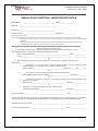
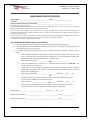
complete both the Annual Vehicle Inspector certification (page 52 hereof) and the Brake Inspector
Page 43 of 54
CCM M&R Procedures Manual
Version 4.1 June 1, 2013
certification (page 53 hereof) for each mechanic it employs or utilizes to make those repairs. A copy of
the form is to be kept at the vendor’s facility and another given to the pool manager. The pool manager
will keep the forms and will check to ensure only mechanics certified to make brake repairs or FMCSA
Periodic Annual inspections are performing those tasks.
Section 11 CCM AUDIT SAFETY CHECKS
Below is a list of some common safety violations for which everyone should be on lookout when
performing audits. The absence of finding such violations does not mean the repairer / facility is safe,
just that they were not found. Failure to spot these items does not constitute CCM endorsement or
certification of vendors practices.
Inadequate / inappropriate protective clothing for workers including shoes, hard hats, gloves
and protective glasses
Difficulty being seen – lack of reflective vests
Mechanic’s failure to chock chassis wheels when working underneath
Precariously lifting container high off bolster while working on bolster / pin / lock
Using a box or crate to support a chassis / axle as opposed to proper jack stands
Not caging tires when airing, not airing safely with extension chucks, standing in front of tire
when airing, not having auto-pressure shutoff, transporting and handling fully-inflated tires
Failing to inspect rim lock rings, failing to read markings and match lock rings & rim bases, OR
using heavily corroded, damaged, dented, bent rims and lock rings
Not caging spring brakes – attempting to adjust spring break clamps – taking spring brakes apart
Smoking near combustibles
Standing in water when welding or using electrical tools
Crawling into stacks of chassis for inspection or repair – for any purpose
Walking in between or behind mounted containers/chassis, especially when there are tractors /
hostlers operating backing into the chassis or adjacent chassis
Not yielding to container handlers / forklifts / hostlers - you can see them better than they are
able to see you
Walking underneath a container being repositioned or standing under a straddle carrier with or
without a container.
CCM and the pool managers reserve the right and will conduct audits of the M&R vendors for
compliance with this manual. It is incumbent upon the M&R vendors to develop and implement a
quality program of self-audits to ensure these policies and procedures are followed.
Page 44 of 54
CCM M&R Procedures Manual
Version 4.1 June 1, 2013
Section 12 M&R Vendor Self Audit Process
All M&R Vendors working on CCM managed chassis are required to control quality and safety through
self-audits of work performed on CCM equipment. Self-audits are the best way to ensure quality control
and 100% involvement is required. Vendors will not be penalized for poor self-audit results. Vendor is
expected to fix any problems uncovered in their own audits. Vendors must train and/or discipline
mechanics to ensure improvement and maintain the highest level of quality. The purpose of the selfaudit is to ensure that CCM audits and post-inspections are positive. Poor results found during CCM
audits could likely result in penalties or sanctions, including possible cancellation of the M&R Vendor
Agreement. Poor results found by CCM will certainly result in a requirement for heavier management
involvement and increased self-audits. Poor CCM audits are avoidable through a quality self-audit
program.
1. Vendor Management to observe conditions in their shops, facilities or assigned ramps
for safety compliance, part supplies, proper tools & equipment and quality of repairs.
2. Vendor Management to perform post-inspections on an adequate quantity of
mechanics’ work orders or repair estimates in order to ensure chassis are being repaired
properly and charges to the pool are accurate. CCM may specify how many inspections
are required, based upon CCM’s audit results of the vendor. A minimum of 10% of the
work orders require a Supervisor’s signature, including Roadability and mounted chassis
areas. This Supervisor is responsible for the work completed by mechanics under his
supervision.
3. Vendor Management to keep records of each chassis inspection and provide a summary
report to CCM monthly reports. More detailed records may be required depending
upon CCM’s audit results of the vendor. CCM may specify more detailed records
needed such as photos, invoice copies, work order copies, etc.
4. Vendor Management shall maintain their inspection details and use the Chassis Audit
Inspection form provided by CCM. Depending upon CCM’s audit results, vendor may be
required to maintain specific forms to demonstrate full quality control is in place.
5. Vendor management to conduct post-inspections in conjunction with the self-audit
process. Included at the end of this document is a form developed by CCM that details
the severity of violations. It shows which are OOS violations, citations or CCM
requirements and includes the FMCSR section for each type of repair. It is
recommended that mechanics and supervisors all have a copy of this form with them
when conducting audits or inspections on CCM equipment.
6. All Wheel End Repairs require a supervisor’s verification that work was completed
properly. The mechanic and supervisor must sign the work order to confirm verification
and the mechanic’s and supervisor’s name must be included on the invoice (comment
section).
7. Any sub-par audits should be maintained in the mechanic’s personal file as well as any
training or disciplinary actions.
Page 45 of 54
CCM M&R Procedures Manual
Version 4.1 June 1, 2013
Section 13 TIRE SAFETY
The proper handling of tire and rims is an important safety matter that affects everyone involved in the
maintenance and management of the equipment as well as the general public.
In accordance with CCM’s concern for the safety of all, please note the following and attached
procedures to be observed for safe handling and installation of tires on chassis in service with the pools.
We encourage all of you to review these procedures and include a review of tire safety procedures in
your regular audit and safety processes.
Please note that for further information on this subject we recommend that you visit the link below
from the Accuride Corporation web site and review their on-line safety manual. The link is:
http://www.accuridecorp.com/files/2012/10/Accuride-Wheels-Rim_Wheel-Safety-and-Service-ManualACC7-0002-Rev-4-06-22-12.pdf.
Please also note that all repair vendors should observe all OSHA and DOT guidelines regarding the safe
handling of tires and two piece rims.
If you have any questions on the material contained please contact the CCM M&R Technical Manager or
the CCM Director or Maintenance at your earliest opportunity.
Section 14 USED RIM INSPECTION PROCEDURE
I. GENERAL:
1. All inspections are to be performed by qualified mechanics and / or personnel.
2. Always follow Industry safety procedures, including but not limited to eye and ear protection.
3. Follow ALL OSHA (Occupational Safety and Health Administration) safety procedures for tire and
rim handling and rim to lock-ring matching.
4. Follow ALL TMC (Technology and Maintenance Council) recommended practices for out of
service conditions. This procedure and its contents are in accordance with TMC recommended
practice #RP-222-B
5. This procedure should be done ONLY to rims that have a 100% deflated tire (removed valve
core) or the rim is dismounted from the tire. NEVER check a rim while mounted with an inflated
tire.
6. This procedure is only applicable to 7.5 x 20 two piece open demountable truck trailer rims.
Page 46 of 54
CCM M&R Procedures Manual
Version 4.1 June 1, 2013
II. PROCESS:
1. Do a complete visual check of the rim. If any of the following exist, remove the rim from service
and scrap. (Note: Special attention should be given to the circumference of the rim base at the lockring seat)
Bent flange AWAY from bead beyond 3/8”. No more than 2 bends per rim.
Bent flange TOWARDS bead, not acceptable.
Bent web or base not acceptable.
Rim and lock-ring have heavy rust, corrosion, or pitting,
Any deformation, cracks, welds, or repairs to rim or lock-ring.
Lock-rings which are round, bent out of shape, or worn and no longer fit properly.
Unable to read identification marks.
Gap or improper seat between lock-ring and rim shoulder for the circumference of the rim.
Damaged, missing, welded, or altered stops.
2. Do a physical check of the rim with a “chipping” hammer:
Strike the rim with the pointed side of the hammer around the perimeter of the rim base.
Alternate strikes along the width of the rim base.
Give special attention to strikes on the lock-ring side of the rim base.
The sound of each strike should be “deep and hard”.
If any of the following occurs, remove the rim from service and discard:
1. Strikes have improper or unusual sound.
2. Excessive rust chips from striking.
3. Fractures, punctures, or dents occur during striking.
NOTE: If a rim has borderline inspection results, or is questionable in anyway whatsoever, remove
from service and scrap.
Section 15 DVER RECEIPT PROCEDURE
The following procedure will be used when a DVER is received from the Motor Carrier (MC), given to
CCM and finally to the M&R vendor (MRV) for resolution. In all instances the PM for each pool must
receive the DVER. Under no circumstances will CCM allow a MC to turn a DVER in to an M&R Vendor or
attempt to turn one in at an unmanned gate.
Page 47 of 54
CCM M&R Procedures Manual
Version 4.1 June 1, 2013
SCENARIO 1
DVER IS EMAILED FROM THE MC TO THE PM
1.
2.
3.
4.
5.
6.
7.
8.
9.
10.
11.
Driver receives a DVER during a roadside inspection.
Driver gives the DVER to his dispatcher.
Dispatcher emails DVER to the CCM pool location, within 24 hours of his receipt of DVER.
CCM staff monitors gate transactions to determine when chassis in question returns to a facility.
a. CCM staff will instruct terminal operator to advise when unit is received at gate.
Once unit is received, CCM staff will give DVER to the designated M&R Vendor (MRV) on the
facility for repair.
CCM will place hold on equipment (if able to do so in the terminal operating system) AND will
instruct MRV to place OOS sticker on the front bolster or on the 7 way plug.
Once repairs are completed, MRV will notify CCM and remove OOS sticker and replace with
green OK or available decal/sticker.
a. MRV will provide CCM with documentation repairs were completed immediately upon
completion of the repairs.
CCM staff will remove unit from hold in TOS (if applicable).
MRV will include copy of DVER with invoice for repairs (added as an attachment in chassis.com)
CCM notifies issuing agency that repairs were completed and submits required documentation.
CCM will keep a registry of ALL DVER’s received on a spreadsheet. The spreadsheet will show
the following information:
a. Date of DVER
b. DVER identification number
c. Chassis Number
d. Trucking Company and DOT number (if available)
e. Description of infraction from DVER
f. Date DVER infraction was actioned (repaired or inspected only). If no repair was
required:
i. State reason, i.e. no damage was found to be in violation per DVER (it could be
the MC repaired the unit prior to return)
g. Invoice number and date of repair.
h. Amount of repair
i. Repair vendor
j. Date DVER sent back to issuing agency
Page 48 of 54
CCM M&R Procedures Manual
Version 4.1 June 1, 2013
SCENARIO 2
DVER IS RECEIVED WITH NO DEFECTS
In the event a “NO DEFECT” DVER is received, either through the mail, from a Motor Carrier, etc., that
NO DEFECT DVER is to be kept on file at the CCM office and not discarded.
Section 16 Procedure for Clearing Driver Vehicle Inspection Reports (DVIRs)
Identified below are scenarios where equipment enters a terminal, has a DVIR with a reported
defect (RCD) and the procedures that CCM staff require of the Terminal Operator and M&R
Vendor.
The Terminal Operator may or may not have the capability to place units OOS (apply gate
holds). These procedures will address all options. M&R Vendors and Terminal Operators
should communicate with CCM to confirm which scenario applies to their operation.
CCM has designated specific M&R Vendors to act upon addressing any Roadability Component
Defect (RCD) reported via a Driver Vehicle Inspection Report. M&R Vendors are assumed to be
registered in the designated M&R system with its preferred method (i.e. email or EDI) to
receive notices of DVIRs with defects (RCDs).
FOR MOTOR CARRIERS
Motor Carriers should instruct their drivers to turn in DVIR’s with defects. This will help CCM
properly maintain the equipment. Drivers should be especially cognizant of defects they
discover to brakes or wheel alignment and should report these defects without hesitation when
entering a facility.
WHAT IS REQUIRED TO CLEAR A DVIR?
DVIR’S can be cleared using one of the following scenarios:
1. M&R Vendor completes the repairs as noted on a DVIR and submits an invoice to the
designated M&R system using the Repair Type “DVIR”. The M&R system will
automatically clear DVIR’s with one (1) RCD.
2. Some systems, namely chassis.com, will NOT automatically clear a DVIR with more than
one (1) RCD. Those will have to be cleared manually by the M&R Vendor.
Page 49 of 54
CCM M&R Procedures Manual
Version 4.1 June 1, 2013
3. All repairs made pursuant to a DVIR shall be completed in the designated M&R system using the
Repair Type “DVIR”.
SCENARIO 1:
DVIR IS DELIVERED ELECTRONICALLY TO THE TERMINAL OPERATOR TO PUT THE CHASSIS OOS
IN ITS TERMINAL OPERATING SYSTEM
1. M&RV will receive message from DRS that unit is being returned to terminal with RCD on DVIR.
2. M&RV will coordinate with Terminal Operator to advise when unit is received and location of
unit on terminal.
a. M&RV will locate chassis and place RED OOS sticker on the bolster or in the 7 way plug.
3. M&RV will inspect and repair RCD damages or note that repairs are not required.
a. If M&RV cannot find damages to repair from the DVIR, he will generate an inspection
report indicating the same, and enter the inspection into the designated M&R system
using the “DVIR” Repair Type.
b. M&RV will also ensure the entire chassis is acceptable per the CCM Systematic
Maintenance procedure.
c. If the cost to repair the chassis is higher than the M&RV auto limit, the M&RV has to
obtain approval for the repair from CCM.
d. All repairs, once completed, are to be entered into the designated M&R system using
the Repair Type “DVIR”.
4. M&RV will remove the OOS sticker and replace with a GREEN ‘OK’ or available sticker.
5. M&RV will advise Terminal Operator to make unit available in TOS.
6. M&RV will invoice the pool for the inspection (no repairs) or repairs and prioritize the invoice
processing to the "top of the pile".
SCENARIO 2
DVIR IS DELIVERED TO THE M&R VENDOR TO PUT THE CHASSIS OOS
1. When possible, the unit should be placed in OOS status by the M&RV directly into the TOS.
2. M&RV will locate unit, place a RED OOS sticker on the front bolster or on the 7 way plug.
3. M&RV will inspect and repair RCD damages or note that repairs are not required.
a. If M&RV cannot find damages to repair from the DVIR, he will generate an inspection
report indicating the same, and enter the inspection into the designated M&R system
using the “DVIR” Repair Type.
Page 50 of 54
CCM M&R Procedures Manual
Version 4.1 June 1, 2013
b. M&RV will also ensure the entire chassis is acceptable per the CCM Systematic
Maintenance procedure.
c. If the cost to repair the chassis is higher than the M&RV auto limit, the M&RV has to
obtain approval for the repair from CCM.
d. All repairs, once completed, are to be entered into the designated M&R system using
the Repair Type “DVIR”.
4. M&RV will remove the OOS sticker and replace with a GREEN ‘OK’ or available sticker.
5. If possible, the M&RV will make the unit available in TOS.
6. M&RV will invoice the pool for the inspection (no repairs) or repairs and prioritize the invoice
processing to the "top of the pile".
CCM POOL MANAGERS AND M&R MANAGERS
CCM managers must ensure DVIR’s are cleared from the designated M&R system within seven (7) days
(one week) of receiving notification of a DVIR with RCD’s. When using chassis.com as the designated
M&R system, follow the guidelines below:
1. Log in to the designated M&R system DVIR screen.
a. Enter “Date From” going back several months (to the beginning of the pool using the
designated M&R system) to ensure all open DVIR’s are captured.
b. Enter “Defects” – YES; and “Release” – NO
c. Under “Inspection Type”, Click - End of Trip DVIR
d. Click “Search”.
e. Click “EXCEL” to move open DVIR’s to an EXCEL spreadsheet.
2. With the cursor on Line 1, click Data, then Filter, to sort data.
3. Once the data is sorted, proceed with each location to find open DVIR’s. The designated M&R
system will have to be checked against the DVIR date for any repairs performed after the date
of the DVIR.
4. Once a repair is found that should clear a DVIR, ensure the M&R vendor clears the DVIR using
the “DVIR” repair type.
5. CCM staff can also clear a DVIR by going to the DVIR screen in the designated M&R system.
From there click DVIR then Release DVIR. Enter the DVIR number from the spreadsheet and
click Search. Once the DVIR is found, check it on the far left and enter a reason for clearing the
DVIR on the far right. Click release and the DVIR will clear.
CCM management should view the list of DVIR’s received daily and advise the facility M&R Vendor(s) of
receipt of same. CCM management should ensure Vendor repairs the chassis and clears the DVIR as
soon as possible.
Page 51 of 54
CCM M&R Procedures Manual
Version 4.1 June 1, 2013
ANNUAL VEHICLE INSPECTION – INSPECTOR CERTIFICATION
M&R VENDOR: _________________________________________________ DATE: _____________________
LOCATION: ____________________________________________________
City, state zip __________________________________________________
Name of Inspector: _____________________________________________ Employee ID: ________________
396.19 Inspector Qualifications
It shall be the M&R vendor’s responsibility to ensure that the individual(s) performing an annual inspection under 396.17 is qualified as follows:
1.
Understands the inspection criteria set forth in 49 CFR Part 393 and Appendix G of this subchapter and can identify defective
components.
2.
Is knowledgeable of and has mastered the methods, procedures, tools and equipment used when performing an inspection; and
3.
Is capable of performing an inspection by reason of experience, training, or both as follows:
I AM QUALIFIED TO PERFORM AN ANNUAL INSPECTION OF INTERMODAL EQUIPMENT BASED ON THE FOLLOWING:
(Check and complete the appropriate sections)
_____ a). Successfully completed a State or Federal sponsored training program or has a certificate from a State
which qualifies this person to perform Intermodal equipment safety inspections.
Name for Program/Certificate _________________________________________________ Date ________________
Location ________________________________________________________________________________________
OR
_____ b). Have a combination of training or experience totaling at least one (1) year. Training and/or experience
may consist of:
1. _____Participation in a truck manufacturer sponsored training program or similar commercial training
program designed to train students in truck operations and maintenance.
Name of Program ___________________________________________How Long? _______Mo _______ Yrs
OR
2.
_____Experience as a mechanic or inspector working on Intermodal Equipment;
Name of M&R Vendor for which you worked_____________________________ Total Mo/Yrs___________
3.
_____Experience as a mechanic or inspector in truck/chassis maintenance at a commercial garage, leasing
company or similar facility;
Name of Facility: ______________________________________________Total Mo/Yrs _________________
4.
Experience as a commercial inspector for a State or Federal agency.
Name of Government Agency ___________________________________ Total Mo/Yrs _________________
OR
OR
Signature of Inspector ___________________________________________________________ Date ______________________
I hereby certify that the mechanic/inspector mentioned above meets the requirements for a qualified inspector to perform the
annual vehicle Inspection in compliance with the US Department of Transportation regulations for qualified inspectors.
Name of Owner/Supervisor (Print) ___________________________________________________________________________
Signature of Owner/Supervisor ___________________________________________________ Date ______________________
Page 52 of 54
CCM M&R Procedures Manual
Version 4.1 June 1, 2013
BRAKE INSPECTOR CERTIFICATION
M&R VENDOR: ________________________________________ DATE: __________________________
LOCATION: ___________________________________________
NAME OF BRAKE INSPECTOR (PLEASE PRINT): ________________________________________________
396.25 Qualifications of brake inspectors:
(a) Intermodal Equipment Providers (IEP) must ensure that all inspections, maintenance, repairs or service to the brakes of its Intermodal
equipment are performed in compliance with the requirements of this section.
(b) For the purpose of this section, a brake inspector means any employee of an M&R vendor working on Intermodal equipment who is
responsible for ensuring all brake inspections, maintenance, service, or repairs to any Intermodal equipment subject to the IEP’s control, meet
the applicable Federal standards.
(c) No IEP may require or permit any person who does not meet the minimum brake inspector qualifications of paragraph (d) of this section to
be responsible for the inspection, maintenance, service or repair of any brakes on its Intermodal equipment.
(d) The IEP must ensure that each brake inspector is qualified.
I am a qualified Brake Inspector based on the following:
1.
2.
3.
I understand the brake service or inspection task to be accomplished and can perform that task, and
I am knowledgeable of and have mastered the methods, procedures, tools, and equipment used when performing an
assigned brake service or inspection task; and
I am capable of performing the assigned brake service or inspection by reason of experience, training or both as
follows:
a. I have successfully completed an apprenticeship program sponsored by a State, Federal agency or labor
union, or a training program approved by a State or Federal agency, or have a certificate from a State, which
qualifies me to perform the assigned brake service or inspection task.
Name of Program/Certificate: _________________________________________________
OR
b. I have brake-related training or experience or a combination thereof totaling at least ONE YEAR. Such
training or experience shall consist of:
i. Participation in a training program sponsored by a brake or vehicle manufacturer or a similar commercial
training program designed to train students in brake maintenance or inspection similar to the assigned
brake service or inspection tasks:
Name of Program/Certificate: _____________________________ How Long? _____Mo ______Yrs
OR
ii. Experience performing brake maintenance or inspection similar to the assigned brake service
or inspection task in a M&R vendor maintenance program:
Name of Employer _______________________________________How Long? _____Mo ______Yrs
OR
iii. Experience performing brake maintenance or inspection similar to the assigned brake service
or inspection task at a commercial garage, fleet leasing company or similar facility:
Name of Employer _______________________________________How Long? _____Mo _____Yrs
Signature of Brake Inspector: _________________________________________________ Date: __________________
Signature of Company Rep: ___________________________________________________ Date: __________________
Page 53 of 54
CCM M&R Procedures Manual
Version 4.1 June 1, 2013
Acknowledgements
This manual contains the procedures and policies of CCM in force at the time of publication. By
signing below, you acknowledge that you have read, understand, and agree to comply with the
policies and procedures contained herein.
Repair Vendor
CCM
_____________________________
______________________________
Company Name
LOCATION
______________________________
______________________________
Title
Title
______________________________
______________________________
Name(Print)
Name(Print)
______________________________
_______________________________
Signature
Signature
X_________________________________
X____________________________________
Page 54 of 54