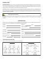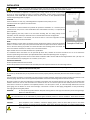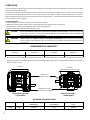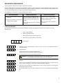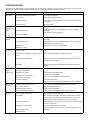
1
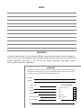
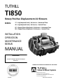
TUTHILL TI850 Rotary Positive Displacement Air Blowers SERIES: 17 – Lip/Labyrinth Seals / Air Service – Horizontal Flow 46 – Lip/Labyrinth Seals / Air Service – Vertical Flow 87 – Slinger/Piston Ring Seals / Air Service – Horizontal Flow 88 – Slinger/Piston Ring Seals / Air Service – Vertical Flow INSTALLATION OPERATION MAINTENANCE REPAIR MANUAL WARNING DO NOT OPERATE BEFORE READING MANUAL. LEADING THE SEARCH FOR INNOVATIVE SOLUTIONS 4840 West Kearney Street Springfield, Missouri USA 65803-8702 Tel 417 865-8715 800 825-6937 Fax 417 865-2950 E-mail: [email protected] 05/2006 http://vacuum.tuthill.com SAFETY INSTRUCTIONS 1. Do not operate before reading the enclosed instruction manual. 2. Use adequate protection, warning and safety equipment necessary to protect against hazards involved in installation and operation of this ! WARNING ! WARNING Keep body and clothing away from machine openings WARNING ! Hearing Protection Required Do not operate without guards in place ! CAUTION Do not touch hot surfaces SAFETY WARNING Keep hands and clothing away from rotating machinery, inlet and discharge openings. Blower and drive mounting bolts must be secured. Drive belts and coupling guards must be in place. Noise level may require ear protection. Blower heat can cause burns if touched. TUTHILL VACUUM & BLOWER SYSTEMS Springfield, MO USA NOTICE The above safety instruction tags were attached to your unit prior to shipment. Do not remove, paint over or obscure in any manner. Failure to heed these warnings could result in serious bodily injury to the personnel operating and maintaining this equipment. 2 TABLE OF CONTENTS SECTION PAGE SAFETY INSTRUCTIONS & WARNING TAGS 2 SAFETY PRECAUTIONS 3 INTRODUCTION 4 OPERATING DATA & FLOW DIRECTION BY ROTATION 4 INSTALLATION 5 LUBRICATION & OIL CAPACITIES 6 MAXIMUM OPERATING LIMITS 6 PREVENTATIVE MAINTENANCE 7 STARTUP CHECKLIST 7 TROUBLESHOOTING 8 RECOMMENDED SHUTDOWN PROCEDURE 9 DISASSEMBLY 10 ASSEMBLY 11 – 13 INTERNAL ASSEMBLY DRAWING & PARTS LIST 14 EXTERNAL ASSEMBLY DRAWINGS 15 SEAL & BEARING INSTALLATION TOOLS 16 – 17 RECOMMENDED LUBRICANTS 17 WARRANTY 18 WARRANTY REGISTRATION CARD 19 IMPORTANT In order to assure you of the full benefits of our product warranty, please complete, tear out and return the warranty registration card located on the back cover of this manual, or you can register your product online at http://vacuum.tuthill.com/ product_registration SAFETY PRECAUTIONS For equipment covered specifically or indirectly in this instruction book, it is important that all personnel observe safety precautions to minimize the chances of injury. Among many considerations, the following should particularly be noted: Blower casing and associated piping or accessories may become hot enough to cause major skin burns on contact. Internal and external rotating parts of the blower and driving equipment can produce serious physical injuries. Do not reach into any opening in the blower while it is operating, or while subject to accidental starting. Cover external moving parts with adequate guards. Disconnect power before doing any work, and avoid bypassing or rendering inoperative any safety or protective devices. If blower is operated with piping disconnected, place a strong, coarse screen over the inlet and avoid standing in discharge air stream. Avoid extended exposure in close proximity to machinery with high intensity noise levels. Use proper care and good procedures in handling, lifting, installing, operating, and maintaining the equipment. Other potential hazards to safety may also be associated with operation of this equipment. All personnel working in or passing through the area should be warned by signs and trained to exercise adequate general safety precautions. Hearing protection may be required depending on silencing capabilities. 3 INTRODUCTION CONGRATULATIONS on your purchase of a new TI850 Industrial Rotary Positive Displacement Blower from Tuthill Vacuum & Blower Systems. Please examine the blower for shipping damage, and if any damage is found, report it immediately to the carrier. If the blower is to be installed at a later date make sure it is stored in a clean, dry location and rotated regularly. Make sure covers are kept on all openings. If blower is stored outdoors be sure to protect it from weather and corrosion. TI850 blowers are built to exacting standards and if properly installed and maintained will provide many years of reliable service. We urge you to take time to read and follow every step of these instructions when installing and maintaining your Blower. We have tried to make these instructions as straightforward as possible. We realize getting any new piece of equipment up and running in as little time as possible is imperative to production. WARNING: Serious injury can result from operating or repairing this machine without first reading the service manual and taking adequate safety precautions. IMPORTANT: Record the blower model and serial numbers of your machine in the OPERATING DATA form below. You will save time and expense by including this reference identification on any replacement part orders, or if you require service or application assistance. OPERATING DATA It will be to the user’s advantage to have the requested data filled in and available in the event a problem should develop in the booster or the system. This information is also helpful when ordering spare parts. Model No. __________________________________ V-Belt Size ______________ Length _____________ Serial No. __________________________________ (Recorded from nameplate on unit) Type of Lubrication: _____________________________ Startup Date ________________________________ ________________________ Blower RPM ________________________________ Pressure ___________________________________ Blower Sheave Diameter ______________________ Vacuum ___________________________________ Motor Sheave Diameter _______________________ Any other special accessories with this unit Motor RPM _______________ HP ______________ _________________________________________ FLOW DIRECTION BY ROTATION Refer to the illustrations below before installing inlet and discharge piping. VERTICAL FLOW 4 HORIZONTAL FLOW INSTALLATION WARNING: Users must provide adequate protection, warning and safety equipment necessary to protect personnel against hazards involved in the installation and operation of this equipment in the system or facility. Do not use air blowers on explosive or hazardous gases. Casing pressure must not exceed 25 PSIG (1.72 bar g). Each size blower has limits on pressure differential, running speed, and discharge temperature, which must not be exceeded. These limits are shown on the Specification Sheet "Maximum Operating Limits” on page 6. LOCATION Install the blower in a clean, dry, and well lighted area if possible. Leave plenty of room around the blower for inspection and maintenance. FOUNDATION We recommend a solid foundation be provided for permanent installation. It is necessary that a suitable base be used, such as a steel combination base under blower and motor, or a separate sole plate under each. Before tightening the bolts, check to see that both mounting feet are resting evenly on the foundation, shim as necessary to eliminate stress on the base when the bolts are tightened. Where a solid foundation is not feasible, care must be taken to insure that equipment is firmly anchored to adequate structural members. DRIVE When the blower is V-belt driven the sheaves must be positioned so that the hub face of the blower sheave is not more than 1/4" (6.5 mm) from the blower drive end plate and the driver sheave is as close to the driver bearing as possible. Care should be taken when installing sheave onto shaft. The faces of the sheaves should be accurately in line to minimize belt wear. Examples of Soft Foot Adjust the belt tension to the belt manufacturer’s specifications. For installations where the blower is to be operated by direct drive, selection of the driver should be such as not to exceed the maximum speed ratings of the blower. (See Specification Sheet “Maximum Operating Limits” on page 6.) A flexible type coupling should be used to connect driver and blower shafts. The two shafts must be aligned within .005” (.13 mm) T.I.R. (Total Indicated Runout) Coupling face run out .003” (.8 mm ) T.I.R. PROTECTIVE MATERIALS Remove protective materials from the shaft. Remove the protective covers from the inlet and outlet ports and inspect the interior for dirt and foreign material. WARNING: Keep hands, feet, foreign objects and loose clothes from inlet and outlet openings to avoid injury or damage if lobes are to be rotated at this point. LUBRICATION Do not start up the blower until you are positive that it has been properly and fully lubricated. (See Lubrication Section on page 6.) PIPING Inlet and outlet connections on all blowers are large enough to handle maximum volume with minimum friction loss. Maintain same diameter piping. Silencers must not be supported by the blower. Stress loads and bending moments must be avoided. Be certain all piping is clean internally before connecting to the blower. We recommend placing a 16-mesh wire screen backed with hardware cloth at or near the inlet connections for the first 50 hours of use until the system is clean. Make provisions to clean the screen after a few hours of operation and completely discard it once the system is clean, as it will eventually deteriorate and small pieces going into the blower can cause serious damage. A horizontal or vertical air flow piping configuration is easily achieved by rearranging the mounting feet position. WARNING: Do not operate equipment without adequate silencing devices since high noise level may cause hearing damage. (Reference OSHA Standards.) RELIEF VALVES We recommend the use of relief valves to protect against excessive pressure or vacuum conditions. These valves should be tested at initial start-up to be sure they are properly adjusted to relieve at or below the maximum pressure differential rating of the blower. CAUTION: Upon completion of the installation, and before applying power, rotate the drive shaft by hand. It must move freely. If it does not, look for uneven mounting, piping strain, excessive belt tension or coupling misalignment or any other cause for binding. If blower is removed and still does not rotate freely, check inside the blower housing for foreign material. 5 LUBRICATION Every Tuthill blower is factory tested, oil drained and shipped dry to its installation point. Both independent oil reservoirs must be filled to the proper level before operation. Shaft bearings at the gear end of the blower are splash lubricated by one or both gears dipping into an oil reservoir formed in the gear end plate and cover. Shaft bearings at the drive end of the blower are lubricated by a slinger assembly dipping into an oil reservoir. Before starting the blower, fill oil sumps as shown below under “Filling Procedure.” Tuthill approved mineral-based, synthetic and food grade lubricants are listed on page 17. FILLING PROCEDURE 1. Remove fill plugs or breathers from both gear end and drive end plates. 2. SLOWLY pour oil through fill until oil appears in the oil sight glass. Bring oil level to center of sight glass. 3. Verify oil level is at proper level in BOTH gear end and drive end sight glasses. 4. Replace fill plugs or breathers that were removed in step 1. CAUTION: Do not start the blower until you are certain that oil is in BOTH ends of the blower. Check BOTH sight glasses to ensure that oil levels are correct before starting. Operation of the blower without proper lubrication will cause the blower to fail and void its warranty. WARNING: NEVER ATTEMPT TO CHANGE OIL WHILE THE BLOWER IS IN OPERATION. Failure to heed this warning could result in damage to the equipment and/or serious personal injury. Oil level must be checked while the blower is not running. APPROXIMATE OIL CAPACITIES * Horizontal Air Flow (17/87 Series) GEAR END DRIVE END 20 ounces (.59 L ) 24 ounces (.71 L) Vertical Air Flow (46/88 Series) GEAR END DRIVE END 35 ounces (1.04 L) 39 ounces (1.15 L) * Oil capacities are based on filling from dry condition. Less oil may be needed depending on emptiness of oil reservoir(s) after draining. Always fill the gear housing until oil drips out of the oil level hole. Replace plugs in their respective holes. Following this procedure will insure proper oil level. Fill Plugs Breathers (Note: Breathers must be on top) Sight Glasses (Fill to center) Magnetic Drain Plugs (always on bottom of blower) HORIZONTAL AIR FLOW (17/87 SERIES) VERTICAL AIR FLOW ** (46/88 SERIES) MAXIMUM OPERATING LIMITS 6 MODEL RPM PRESSURE PSIG (mbar g) VACUUM In. Hg (mbar g) TEMPERATURE RISE F° (C°) TI850 3000 20 (1380) 17 (575) 300 (166) PREVENTATIVE MAINTENANCE A good maintenance program will add years of service to your blower. A newly installed blower should be checked frequently during the first month of operation, especially lubrication. Check oil level in both the drive end and gear end of the blower and add oil as needed. Complete oil changes are recommended every 1000 operating hours, or more frequently depending on the type of oil and oil operating temperature. The following is recommended as a minimum maintenance program. DAILY MAINTENANCE WEEKLY MAINTENANCE MONTHLY MAINTENANCE 1. Check and maintain oil level, and add oil as necessary. 1. Clean all air filters. A clogged air filter 1. Inspect the entire system for leaks. can seriously affect the efficiency of the 2. Inspect condition of oil and change if blower and cause overheating and oil 2. Check for unusual noise or vibration (See necessary (see page 6) usage. Troubleshooting on page 8) 3 Check drive belt tension and tighten if 2. Check relief valve to assure it is operating necessary. properly START-UP CHECKLIST We recommend that these startup procedures be followed in sequence and checked (√) off in the boxes provided in any of the following cases: During initial installation After any shutdown period After maintenance work has been performed After blower has been moved to a new location Date Checked 1. Check the unit for proper lubrication. Proper oil level cannot be over-emphasized. Refer to Lubrication Section. 2. Check Alignment. For Direct Drive: Check coupling and shaft alignment. For Belt Drive: Check for proper belt alignment and tension. 3. Turn the rotors by hand to be certain they do not bind. WARNING: Disconnect power. Make certain power is off and locked out before touching any rotating element of the blower, motor or drive components. 4. "Bump" the unit with the motor a few times to check rotation and to be certain it turns freely and smoothly. 5. Start the unit and operate it for 30 minutes at no load. During this time. feel the cylinder for hot spots. If minor hot spots occur, refer to the Troubleshooting Section (page 8). 6. Apply the load and observe the operation of the unit for one hour. Check the unit frequently during the first day of operation. 7. If minor malfunctions occur, discontinue operation and refer to the Troubleshooting Section (page 8). 7 TROUBLESHOOTING Although Tuthill TI850 blowers are well designed and manufactured, problems may occur due to normal wear and the need for readjustment. The chart below lists symptoms that may occur along with probable causes and remedies. SYMPTOM PROBABLE CAUSE REMEDIES Loss of oil. Gear housing not tightened properly. Tighten gear housing bolts. Lip seal failure. Disassemble and replace lip seal. Insufficient sealant. Remove gear housing and replace sealant. (See Disassembly section on page 10) Loose drain plug. Tighten drain plug. Excessive Improper lubrication. bearing or gear wear. Excessive belt tension. Correct oil level. Replace dirty oil. (See Lubrication section on page 6) Check belt manufacturer’s specifications for tension and adjust accordingly. Check carefully, realign if necessary. Coupling misalignment. Lack of volume. Slipping belts. Check belt manufacturer’s specifications for tension and adjust accordingly. Worn lobe clearances. Check for proper clearances (See Assembly Clearances on page 13) Increase blower speed within limits. Speed too low. Check system to assure an open flow path. Obstruction in piping. Knocking. Excessive blower temperature. Unit out of time. Re-time. Distortion due to improper mounting or pipe strains. Check mounting alignment and relieve pipe strains. Excessive pressure differential. Reduce to manufacturer’s recommended pressure. Examine relief valve and reset if necessary. Worn gears. Replace timing gears (See Disassembly and Inspection section on page 10) Too much or too little oil in gear reservoir. Check oil level. (See Lubrication section on page 6) Too low operating speed. Clogged filter or silencer. Increase blower speed within limits. Excessive pressure differential. Remove cause of obstruction. Elevated inlet temperature. Reduce pressure differential across the blower. Worn lobe clearances. Reduce inlet temperature. Check for proper clearances (See Assembly Clearances on page 13) Rotor end or tip drag. Vibration. Insufficient assembled clearances. Correct clearances (See Assembly Clearances on page 13) Case or frame distortion. Check mounting and pipe strain. Excessive operating pressure. Reduce pressure differential. Excessive operating temperature. Reduce pressure differential or reduce inlet temperature. Belt or coupling misalignment. Check carefully, realign if necessary. Lobes rubbing. Check cylinder for hot spots, then check for lobe contact at these points. Correct clearances (See Assembly Clearances on page 13). Check condition of gears and bearings; replace if necessary. Worn bearings or gears. Possible buildup on casing or lobes, or inside lobes. Remove buildup and restore clearances. Unbalanced or rubbing lobes. Check mounting and tighten if necessary. Driver or blower loose. Check pipe supports, check resonance of nearby equipment, check foundation. Piping resonance. 8 RECOMMENDED SHUTDOWN PROCEDURE TO MINIMIZE RISK OF FREEZING OR CORROSION When high humidity or moisture is present in an air piping system, condensation of water can occur after the blower is shut down and the blower begins to cool. This creates an environment favorable to corrosion of the iron internal surfaces, or in cold weather, the formation of ice. Either of these conditions can close the operating clearances, causing the blower to fail upon future start-up. The following shutdown procedure outlined below minimizes the risk of moisture condensation, corrosion and freezing. Care must be taken so as not to overload or overheat the blower during this procedure. 1. Isolate the blower from the moist system piping, allowing the blower to intake atmospheric air. Operate the blower under a slight load allowing the blower to heat within safe limits. The heat generated by the blower will quickly evaporate residual moisture. 2. For carpet cleaning applications, after the work is completed, simply allow the blower to run a few (3-5) minutes with the suction hose and wand attached. The suction hose and wand will provide enough load to the blower to evaporate the moisture quickly. 3. For extended shutdown, inject a small amount of a light lubricating oil such as 3-in-One® or a spray lubricant such as WD-40® into the inlet of the blower just prior to shutdown. The lubricant will provide an excellent protective coating on the internal surfaces. If using a spray lubricant, exercise care to prevent the applicator tube from getting sucked into the blower. The applicator tube will damage the blower, most likely to the point that repair would be required. 3-in-One and WD-40 are registered trademarks of WD-40 Company. NOTES: 9 DISASSEMBLY 1. Remove all oil drain plug and vent plug from both ends of the blower. Before removing any parts, match mark each component with a punch. This will allow the blower to be reassembled in the same position. Match mark covers, endplates, housing, cover extension, and both rotors. 2. Remove drive key from drive shaft. Remove gear end cover (Item 7). Remove drive end cover (Item 6). This is best accomplished by using to small pry bars at the dowel pins. Tap on cover with a mallet while putting pressure on the cover with the pry bar. The cover will slowly move off the dowel pins. Inspect seal area on drive shaft for groves and burrs. Remove drive shaft seal (Item 17) from drive end cover. Remove oil slinger assemblies (Item 13) 3. Remove bolts (Item 34) and washers (Item 24) from rotor shafts on the gear end. To remove gears(Item 8 & 9) from rotor shafts by using gear puller in figure 1A. Rotate drive gear 3 teeth clockwise from the timing marks on the face of the gears, then remove the driven gear. Inspect gear teeth for wear and pitting. Inspect rotor shaft keyway for wear and damage. CAUTION: Blower rotors must rotate freely in order for timing gears to be removed correctly. If blower rotors do not Figure 1 - Timing Marks on Gears Figure 1A - Illustration of Bar Puller move freely both timing gears must be pulled simultaneously. If gears are removed improperly, this will cause damage to the rotor keyways and possibly to the timing gears. 4. Remove bolts (Item 27) from extension covers (Item 5). Using pry bars and a mallet slowly remove the extension cover from the gear end and drive endplates (Item 4) as explained in step 2. Remove gasket (item 16) from endplates on both gear end and drive end. 5. Use jacking screws on endplate (Item 4), from the housing (Item 3). Rotors (Items 1 & 2) will be removed from the housing. When the gear end endplate is removed. Take a gear puller and attach to the gear endplate with the center of the puller in the center of the rotor shaft. Apply pressure pushing the rotor away from the endplate. Repeat this operation until both rotors have been removed. Remove the inner sleeve of the seal housing from the rotor shafts with a puller. Inspect and clean seal area on the rotor shaft. 6. Remove bearings (Items 9 & 10), seal housing (Item 12), slingers (Item ), bearing shield and bearing shims from endplate. Use a hammer and bar to drive bearing and seal housing from endplates. Inspect bearing wear pattern and seal for wear and heat marks. Clean all parts before inspecting. Check rotors bearing and seal fits for bearing spinning along with seal housing on rotor shaft. Check bearing bores and seal bores in endplate for spinning of bearings and seal housings. DISASSEMBLY NOTES: 10 ASSEMBLY GEAR END ASSEMBLY 1. 2. Check all parts to insure the parts are clean and free of burrs or nick that may have occurred when the blower was being disassemble. Check repair kit for the correct parts needed to complete the assembly of the unit. Make sure you have the proper tooling and training required to assemble the blower. Take the proper time to read the instruction manual before you begin . Seat rotors (Items 1 & 2) on a fixture with the gear end of the rotors upward and in the position as shown in Figure 2. Make sure the drive rotor (Item 1) is in the correct location for the proper flow and rotation required for the application. Install housing (Item 3) over the rotors. Press seal sleeve with piston ring onto rotors shafts until they bottom on the rotors face. NOTE: 3. Use Loctite thread sealant on all bolts and cap screws that are assembled without lockwashers. Press seal housting into the endplate. Install endplate (item 4) onto rotor, make sure the shims on the rotor are still in place. Using a seal pressing tool (see drawing on page 16 for detail), press seal assembly (Item 2) onto rotor shafts. Press lip seal into seal housing in the endplate. Press oil shield (item 15) onto rotor shafts. NOTE: Oil shield is part of the seal assembly but must be pressed on after seal assembly is installed. 4. Lay a straightedge across the top of the rotor shafts (see Figure 3A). Put depth micrometer on the straightedge and measure the distance to the bearing shoulder on the endplate and the distance to the inner seal housing shoulder. Calculate the difference, this will be the amount of .008” to .009” (.20 - .23 mm) bearing shim (Item 12) needed for the proper clearance on the gear end. Install bearing shims and press in gear end bearings (Item 13) until bearing bottom against bearing shims. Tighten bolts to secure endplate to the housing. Install gasket (Item 10) onto end plate and install extension cover (Item 7) onto end plate and tighten securely. Check gear end clearance between the rotors and end plate. NOTE: 6. DRIVE DRIVEN Figure 2– Correct Positioning of Rotor Keyways for Assembly Install bearing retaining washer at this time if blower requires the retainers. Then, check the gear end clearance of the unit. Install gear key (Item 16) into keyway of each rotor. Make sure the keyways are in the correct position for the timing gears as shown in Figure 2. Press timing gear assembly (Item 8&9) onto rotor with timing marks aligned on gear as shown in Figure 4 . Install rotor shaft washer (Item 18) and tighten. Check gear end clearance and record. NOTE: If gear end clearances change, bearing shims may need to added or removed to maintain proper clearances. Figure 3A – Determining amount of Bearing Shims Needed Figure 3B – Bearing Shims Installed 11 Timing Shim on Rotor Shaft Figure 4 – Correct Positioning of Timing Gears for Installation or Removal DRIVE END ASSEMBLY 1. Remove blower from fixture and turn until drive shaft is facing upward. With a straightedge placed on the blower housing, check the clearance between the rotor and the straight edge using feeler gauges. Make sure the drive end has the proper clearances. 2. Place the endplate (Item 4) onto the blower housing. Tighten endplate securely to the housing. Press seal assembly (Item 11) onto rotor until the assemble bottoms on the rotor. Continue the process until both seal assembly are installed. Press the oil shield into place. Install drive end spacers (0.25). NOTE: Oil shield is part of the seal assembly, but must be pressed into place after seal assembly has been installed. 3. Install bearing shields into the endplate. Press bearing (Item 12) into the endplate until the bearing bottoms to the shoulder of the endplate. Install gasket (Item 10), install the extension cover (Item 7) and tighten securely to the endplate. 4. Take Oil slinger assembly ( Item 14) and position onto the drive shaft of the blower. Also install the oil slinger assembly (Item 15) onto the driven rotor. Install rotor washer (Item 24) and bolt (Item 25). Tighten bolt securely to the shaft. 5. Take drive end cover (Item 6) and apply silicone onto cover. Install drive cover onto the extension cover (Item 7) tighten cover securely to cover extension. Install drive shaft seal (Item 17) into drive cover. CAUTION: When installing drive shaft seal, use care not to damage the lip of the seal on the keyway of the drive shaft. Make sure keyway is free of burrs and sharp edges. Install pipe plugs (Item 22) and oil sight glasses (Item 2) into their proper locations which is determined by the direction of flow of the blower. Oil Shield 12 Extension Cover installed Drive End CHECKING INTERLOBE CLEARANCE 7. The outer gear shell is fastened to the inner hub with four cap screws and located with two dowel pins. Adding and removing shims between the gear shell and the inner hub moves the gear shell axially. The helix causes the gear to rotate which changes the clearance between the rotor lobes. Adding .030” (.76 mm) shims thickness will change the rotor lobe clearance by approximately .009“ (.23 mm). The timing shim is formed from a number of .003” (.076 mm)shims that have been laminated together. They are easily peeled off as necessary or added to correct timing. Use feeler gauges to check the clearance at AA (right hand reading) and BB (left had reading) see Figure 5. The clearance should be adjusted so they are as equal between all lobes as possible, usually between .002” to .003“. (.05 – .08 mm) For best results, use feeler gauges no thicker than .006“ (.15 mm). Example: If AA reading is .020” and BB reading is .008”, by removing .021” shims the reading will change .006“. AA should read .014” and BB should read .014“. Remember to place timing marks on center and match when removing or installing a gear. (See Figure 4 on p. 12.) Figure 5. – Checking Interlobe Clearance NOTE: After timing of the rotor has been completed. Check Tip-Port and Tip-Dowel Clearance and record along with gear end and drive end clearances. Tip-Dowel location is when the tip of the rotor is line up with the dowel pins in the housing. Check clearance as near to the dowel as possible. 8. Install rotor washer (Item 18) and bolt (Item 34) on gear end rotor shafts. Tighten securely and apply silicone onto cover. Install gear end cover (Item 7) to cover extension (Item 5) and tighten bolts so cover is fasten securely to the cover extension. 9. Install pipe plugs and sight glasses to the proper location. The direction of flow of the blower will determine their location. ASSEMBLY CLEARANCES Model Gear End Drive End Interlobe Tip-Port Tip-Dowel TI850 .004” – .009” (.10 – .23 mm) .013” –.018” (.33 – .46 mm) .013” – .017” (.33 – .45 mm) .006” –.010” (.15 – .25 mm) .003”– .007” (.08 – .18 mm) ASSEMBLY NOTES: 13 TI850 INTERNAL ASSEMBLY AND PARTS LIST Item Description 14 Qty. Item Description Qty. 1 DRIVE ROTOR 1 25 CAP SCREW, HEX HEAD 2 2 DRIVEN ROTOR 1 26 CAP SCREW, HEX HEAD 1 3 HOUSING 1 27 CAP SCREW, HEX HEAD 16 4 END PLATE 2 28 CAP SCREW, SOCKET HEAD 16 5 COVER EXTENSION 2 29 CAP SCREW, SOCKET HEAD 16 6 DRIVE END COVER 1 30 DOWEL PIN 8 7 GEAR END COVER 1 34 CAP SCREW, SOCKET HEAD 16 8 TIMING GEAR ASSEMBLY 1 35 LOCKWASHER 32 9 BALL BEARING, DOUBLE ROW 2 36 PIPE PLUG 2 10 ROLLER BEARING, CYLINDRICAL 2 37 SHOULDER SCREW 2 11 BEARING SHIM 2 38 LOCKWASHER 2 12 SEAL ASSEMBLY 4 39 HEX NUT 2 13 OIL SLINGER ASSEMBLY, DRIVE 1 40 MOUNTING FOOT TI850 2 14 OIL SLINGER ASSEMBLY DRIVEN 1 50 CAP SCREW, HEX HEAD 4 15 MAGNETIC OIL DRAIN PLUG 2 60 LOCKWASHER 4 16 GASKET 2 70 BREATHER, 2 17 DRIVE SHAFT SEAL 1 80 PORT FITTING 2 21 OIL SIGHT GLASS 2 90 PORT FITTING GASKET 2 22 PIPE PLUG 6 100 CAP SCREW, HEX HEAD 8 23 GEAR KEY 2 110 LOCKWASHER 8 24 WASHER, ROTOR SHAFT 3 TI850 EXTERNAL ASSEMBLY (Reference Parts List on Facing Page) 17/87 SERIES (HORIZONTAL AIR FLOW) 46/88 SERIES (VERTICAL AIR FLOW) NOTES: 15 SEAL & BEARING INSTALLATION TOOL DRAWINGS A 1.200" 5.125" 0.128" 4.500" 0.300" 1.628" 1.908" +.008 -.008 A 3.012" 2.365" 1.954" 2.363" A SECTION A-A .040" x 45° SECTION A-A DRIVE SHAFT SEAL TOOL A CLEARANCE SETTING SPACER 6.200" A 2.300" 0.200" ø 3.502" 3.496" 3.500" 2.850" 2.750" 1.750" 2.375" ø 0.258" 1.750" A .040" x 45° .125" x 45° 0.375" ø 4.321" SECTION A-A +0.001" -0.000" END PLATE PRESS TOOL PILOT END PLATE SEAL PRESS TOOL ø 2.500" 10.550" 10.125" 1.750" ø 0.531" 1.500" .040" x 45° 0.220" A 0.220" 4.125" 1.990" 1.895" +0.005" -0.005" 0.500" R 0.125" 2.750" SECTION A-A A .040" x 45° LONG SHAFT BEARING PRESS TOOL GEAR PRESS SPACER 9.219" 0.750" 9.750" .040" x 45° R .06" A 9.300" 3.405" 2.875" 2.000" A 2.875" 2.000" ø 0.266" 0.625" 0.156" SECTION A-A A 10.125" SECTION A-A PISTON CARRIER AND SLINGER INSTALLATION TOOL 16 ROTOR SHAFT LIP SEAL PRESSING TOOL A SEAL & BEARING INSTALLATION TOOL DRAWINGS 1/2-13UNC-2A BOTH ENDS 0.500" 2.000" 2.000" MATERIAL: TOOL STEEL HEAT TREATED TO 40-42 Rc HYDRAULIC PRESS ROD 2.750" 0.285" 0.500" .094" x 45° R 0.125" 2.375" 1.250" ø 0.313" THRU ALL Ø .422", 2.385" DEPTH 1/2-13 UNC-2B, 2.000" DEPTH 0.625" ø 0.313"THRU ALL 3/8-16 UNC-2B THRU ALL END CAP FOR PRESS ROD RECOMMENDED LUBRICANTS RECOMMENDED MINERAL BASED LUBRICANTS AMBIENT TEMPERATURE SHELL CITGO CHEVRON TEXACO EXXONMOBIL 0° F (-18°C) to 32°F (0°C) TELLUS® PLUS 68 (ISO 68) A/W 68 (ISO 68) RANDO HD 68 (ISO 68) DTE HEAVY MEDIUM (ISO 68) 32o F (0o C) to 90o F (32o C) TELLUS® PLUS 100 (ISO 100) A/W 100 (ISO 100) RANDO HD 100 (ISO 100) DTE HEAVY (ISO 100) 90o F (32o C) to 120o F (50o C) TELLUS® PLUS 150 (ISO 150) A/W 150 (ISO 150) RANDO HD 150 (ISO 150) DTE EXTRA HEAVY (ISO 150) RECOMMENDED SYNTHETIC BASED LUBRICANTS* AMBIENT TEMPERATURE 0o F (-18o C) to 32o F (0o C) o o 32 F (0 C) to 90o F (32o C) 90o F (32o C) to 120o F (50o C) TUTHILL PneuLube™ (ISO 100) PneuLube™ (ISO 150) EXXONMOBIL SHELL SHC 626 (ISO 68) MADRELA® AS 68 (ISO 68) SHC 627 (ISO 100) MADRELA® P 100 (ISO 100) SHC 629 (ISO 150) MADRELA® P 150 (ISO 150) NOTE: Tuthill Vacuum & Blower Systems cannot accept responsibility for damage to seals, O-rings and gaskets caused by use of synthetic lubricants not recommended by Tuthill Vacuum & Blower Systems. * Blowers used in oxygen-enriched service should use only Castrol Brayco 1726 Plus non-flammable, PFPE synthetic lubricant. Blowers used in hydrogen service should use only PneuLube™ synthetic oil. RECOMMENDED MINERAL BASED, FOOD GRADE LUBRICANTS AMBIENT TEMPERATURE Lubricant meeting U.S. FDA regulations 21 CFR 172.878 and 178.3620(a) for direct and indirect food contact Lubricant meeting U. S. FDA regulation 21 CFR 178.3570 governing petroleum products which may have incidental contact with food (formerly USDA H1 requirements) 0o F (-18o C) to 32o F (0o C) CITGO CLARION® 350 FOOD GRADE (ISO 68) CITGO CLARION® A/W 68 (ISO 68) 32o F (0o C) to 90o F (32o C) CONSULT FACTORY CITGO CLARION® A/W 100 (ISO 100) 90o F (32o C) to 120o F (50o C) CONSULT FACTORY CONSULT FACTORY 17 WARRANTY Subject to the terms and conditions hereinafter set forth and set forth in General Terms of Sale, Tuthill Vacuum & Blower Systems (the seller) warrants products and parts of its manufacture, when shipped, and its work (including installation and start-up) when performed, will be of good quality and will be free from defects in material and workmanship. This warranty applies only to Seller's equipment, under use and service in accordance with seller's written instructions, recommendations and ratings for installation, operating, maintenance and service of products, for a period as stated in the table below. Because of varying conditions of installation and operation, all guarantees of performance are subject to plus or minus 5% variation. (Non-standard materials are subject to a plus or minus 10% variation) Product Type Type of Application Atmospheric Air or Process Air Process Gases Other Than Air, New 24 months from date of shipment, or 18 months after initial startup date, whichever occurs first 18 months from date of shipment, or 12 months after initial startup date, whichever occurs first Repair 12 months from date of shipment, or remaining warranty period, whichever is greater 12 months from date of shipment, or remaining warranty period, whichever is greater THIS WARRANTY EXTENDS ONLY TO BUYER AND/OR ORIGINAL END USER, AND IN NO EVENT SHALL THE SELLER BE LIABLE FOR PROPERTY DAMAGE SUSTAINED BY A PERSON DESIGNATED BY THE LAW OF ANY JURISDICTION AS A THIRD PARTY BENEFICIARY OF THIS WARRANTY OR ANY OTHER WARRANTY HELD TO SURVIVE SELLER'S DISCLAIMER. All accessories furnished by Seller but manufactured by others bear only that manufacturer's standard warranty. All claims for defective products, parts, or work under this warranty must be made in writing immediately upon discovery and, in any event within one (1) year from date of shipment of the applicable item and all claims for defective work must be made in writing immediately upon discovery and in any event within one (1) year from date of completion thereof by Seller. Unless done with prior written consent of Seller, any repairs, alterations or disassembly of Seller's equipment shall void warranty. Installation and transportation costs are not included and defective items must be held for Seller's inspection and returned to Seller's Ex-works point upon request. THERE ARE NO WARRANTIES, EXPRESSED, IMPLIED OR STATUTORY WHICH EXTEND BEYOND THE DESCRIPTION ON THE FACE HEREOF, INCLUDING WITHOUT LIMITATION, THE IMPLIED WARRANTIES OF MERCHANTABILITY AND FITNESS OF PURPOSE. After Buyer's submission of a claim as provided above and its approval, Seller shall at its option either repair or replace its product, part, or work at the original Ex-works point of shipment, or refund an equitable portion of the purchase price. The products and parts sold hereunder are not warranted for operation with erosive or corrosive material or those which may lead to build up of material within the product supplied, nor those which are incompatible with the materials of construction. The Buyer shall have no claim whatsoever and no product or part shall be deemed to be defective by reason of failure to resist erosive or corrosive action nor for problems resulting from build-up of material within the unit nor for problems due to incompatibility with the materials of construction. Any improper use, operation beyond capacity, substitution of parts not approved by Seller, or any alteration or repair by others in such manner as in Seller's judgment affects the product materially and adversely shall void this warranty. No employee or representative of Seller other than an Officer of the Company is authorized to change this warranty in any way or grant any other warranty. Any such change by an Officer of the Company must be in writing. The foregoing is Seller's only obligation and Buyer's only remedy for breach of warranty, and except for gross negligence, willful misconduct and remedies permitted under the General Terms of Sale in the sections on CONTRACT PERFORMANCE, INSPECTION AND ACCEPTANCE and the PATENTS Clause hereof, the foregoing is BUYER'S ONLY REMEDY HEREUNDER BY WAY OF BREACH OF CONTRACT, TORT OR OTHERWISE, WITHOUT REGARD TO WHETHER ANY DEFECT WAS DISCOVERED OR LATENT AT THE TIME OF DELIVERY OF THE PRODUCT OR WORK. In no event shall Buyer be entitled to incidental or consequential damages. Any action for breach of this agreement must commence within one (1) year after the cause of action has occurred. July, 2002 18 NOTES IMPORTANT All blowers manufactured by Tuthill Vacuum & Blower Systems are date coded at time of shipment. In order to assure you of the full benefits of the product warranty, please complete, tear out and return the product registration card below, or you can visit our product registration web page at http:// vacuum.tuthill.com/product_registration IMPORTANT All blowers manufactured by Tuthill Vacuum & Blower Systems are date coded at time of shipment. In order to assure you of the full benefits of the product warranty, please complete, tear out and return this product registration card. Company Location City Telephone: ( State/Province ZIP/Postal Code ) E-mail: Model: Serial Number: Country PLEASE CHECK ONE Pneumatic Conveying Food Vacuum Paper Wastewater Date of Purchase: Date of Startup: BY: Gas/Petrochemical Other 19 NO POSTAGE NECESSARY IF MAILED IN THE BUSINESS REPLY MAIL FIRST-CLASS MAIL PERMIT NO. 2912 SPRINGFIELD MO POSTAGE WILL BE PAID BY ADDRESSEE ATTN CUSTOMER SERVICE TUTHILL VACUUM & BLOWER SYSTEMS PO BOX 2877 SPRINGFIELD MO 65890-2150