1
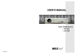
SuperPole™ System
Installation Instructions DC100:
SP-S, SP-HD, SPB-S, SPB-HD, SPB-AK, STP-S, STP-AK, SP-ACP, SP-ACP-AK
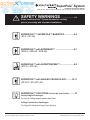
SAFETY WARNINGS .............................2-3
Please read SuperPole™ System Introduction carefully
prior to proceeding with all product installations.
SUPERPOLE™ / SUPERPOLE™ BARIATRIC .................4-5
(SP-S / SP-HD)
SUPERPOLE™ with SUPERBAR™..................................6-7
(SPB-S / SPB-HD / SPB-AK)
SUPERPOLE™ with SUPERTRAPEZE™.........................8-9
(STP-S / STP-AK)
SUPERPOLE™ with ANGLED CEILING PLATE..........10-11
(SP-ACP / SP-ACP-AK)
SUPERPOLE™ SOLUTIONS FOR CEILING CHALLENGES ..........12
Ceiling Height Challenges:
For floor to ceiling ranges greater than 8 feet.
Ceiling Construction Challenges:
For Angled Ceilings and Large Joist Spacing.
HealthCraft Products Inc.,
2790 Fenton Road, Ottawa, Ontario, Canada, K1T 3T7.
DC100 REV D Page 1 of 12
Specifications subject to change without notice.
THANK YOU...
SAFETY CONSIDERATIONS
Thank you for purchasing the SuperPole™ System. We are
confident that you will find the unique design and durable
construction of this HealthCraft™ product to be of great
assistance in your daily routine.
To fully enjoy your SuperPole™ System, please take a few
moments to read these instructions. You should store these
instructions in a safe place for future reference.
WARRANTY
All HealthCraft™ Products are covered by a one year limited
warranty with the exception of hand grips which are subject to
normal wear. Buyer hereby indemnifies, agrees to hold harmless
and defend HealthCraft™ Products Inc. from and against any
and all liabilities, claims, (founded and unfounded), losses,
damages, costs and expenses (including without limitation
consequential damages and reasonable professional fees)
resulting from buyers specification, application, or improper use
of goods described hereon; buyers omission or neglect.
HealthCraft™ Products Inc. does not assume any liability for
damage resulting from services performed by others or faulty
installation, misuse or misapplication of goods sold by
HealthCraft™ Products Inc.
HealthCraft™ Produts Inc. shall not be liable for prospective
profits or special, indirect, or consequential damages, or for the
cost of any corrective work done without HealthCraft™ Products
Inc. prior approval. HealthCraft™ Products Inc. total liability
hereunder shall in no event exceed the purchase price of the
goods specified hereon.
SUPERPOLE™ INSTALLATION / MAINTENANCE
The SuperPole™ System should only be used in locations
where the floor and ceiling surfaces are structurally sound. It
should not be installed on loose floor coverings, in rooms with
radiant ceiling heating, or mobile homes. Not more than 150 lbs
should be exerted on trapeze handle (sitting up assistance only).
If you are not equipped to undertake the outlined work, we would
recommend that you have your SuperPole™ System installed by
a qualified contractor. The extension screw feature of the
SuperPole™ System can generate enough force to damage a
ceiling. Exercise caution when tightening this screw. The
SuperPole™ System can loosen due to settling of the floor or
ceiling, particularly in the first hours and days following
installation and sometimes with a change of season. As a result,
we recommend that you test that the pole is secure, and the
extension screw tightened if needed during this time, and then
on a monthly basis.
CAUTION: It is your responsibility to see that your SuperPole™
System is properly assembled, installed, and cared for. Failure
to follow instructions in this manual could result in serious injury.
WARNING - PATIENT ENTRAPMENT!
The potential risk of entrapment (limb, neck, head, torso)
between the pole and adjacent item (i.e. bed, toilet, etc.) can be
reduced or avoided by the following strategies:
1. Situate the pole at a distance that is considerably smaller or
larger than that which could result in entrapment.
2. Consider situations that could change with time or usage
such as mattress compression, patient movement, bed position
changes due to electrically powered beds, etc.
3. Realize that this product is not intended as a physical
constraint or barrier to exiting the bed.
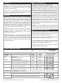
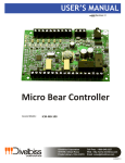
PRODUCT COMPATABILITY CHART
SuperPole™
Floor to ceiling support rail.
300lbs /
136kg
93-99" /
236-251cm
SP-HD
SuperPole™ Bariatric
SuperPole™ with increased weight capacity.
450lbs /
205kg
93-99" /
236-251cm
x
SP-UF
Uni-Fit Extender™
Extension tube attaches to SuperPole™.
300lbs /
136kg
100-120" /
254-305cm
x
SP-ULTRA
SuperPole™ Ultra
Longer version of the SuperPole™.
300lbs /
136kg
121-140" /
307-356cm
SP-CUSTOM
Custom Cut SuperPole™
Floor to ceiling measurements required.
300lbs /
136kg
Less than 93" /
236cm
R
x
TR
A
B
PE
R
SU
SP-S
N
A
G
PE
PL LE
ZE
AT D
E CE
™
IL
U
IN
N
I-F
G
IT
EX
C
TE
EI
L
N
EX IN
D
ER
TE G P
™
N LA
D T
ER E
™
FLOOR TO
CEILING
RANGE
DESCRIPTION
™
USER
WEIGHT
CAPACITY
MODEL
NUMBER
A
(EACH SOLD SEPARATELY)
(EACH SOLD SEPARATELY)
PE
R
FLOOR TO CEILING OPTIONS
ACCESSORIES
x = CANNOT BE USED TOGETHER
SU
= APPLICABLE
x
x
CEILING PLATE ACCESSORIES (EACH SOLD SEPARATELY)
SP-CPE
Ceiling Plate Extender™
Longer plate (30"/76cm) spans wider ceiling joists (24"/61cm spacing).
SP-ACP
Angled Ceiling Plate
Bolts to angled ceilings between 0-45˚. Top plate diameter 18"/45cm.
HealthCraft Products Inc.,
2790 Fenton Road, Ottawa, Ontario, Canada, K1T 3T7.
x
x
x
DC100 REV D Page 2 of 12
Specifications subject to change without notice.
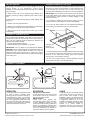
GETTING STARTED...
STANDARD SUPREPOLE™ TOP PLATE
We strongly recommend that you give thought as to the
optimal location of your SuperPole™ System before
installation. The following questions may help you to decide
upon a location:
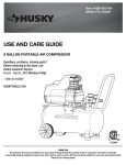
It is recommended that the top plate be installed to span across
two joists in a ceiling as shown below. In cases where this may
not be possible (i.e. one joist only), be sure to test the pole
rigorously after installation to be certain of a secure installation.
a. What motions will you be going through? (pulling up to
standing, lowering to sitting, transferring from chair to toilet,
etc.).
IMPORTANT: The top plate has two holes that may be used to
fix this plate directly to the ceiling or ceiling joists. It is strongly
recommended to install screws to prevent slippage in the
following situations:
b. Where will you need the most support? (while walking, while
lifting, etc.)
c. What is your strongest side/hand?
d. What is your complete transfer path? Will the location allow
for full support over most of your path of motion?
e. Will the pole be far enough away to allow you to stand
comfortably?
1. If you expect to subject the pole to heavy usage (i.e. pole is
used for more than mild support for side to side stability).
2. If you are not able to inspect, or have inspected (and tighten
if neccessary) the extension screw on a monthly basis.
Joist
SUPERPOLE™ BARIATRIC (SP-HD)
For the SuperPole™ Bariatric, verify that both the pole and
ceiling anchor plate are labelled with "Heavy Duty" stickers.
Also note the following physical differences between the
standard and bariatric models:
• Heavier gauge (thicker wall) pole
• Smaller diameter pole receptacle on top plate
IMPORTANT: The top plate for the SuperPole™ Bariatric
MUST BE secured to the ceiling using two fasteners which are
appropriate to the ceiling material. At least one of the two
fasteners should secure directly into a ceiling joist. These
fasteners are intended to prevent the top plate from dislodging
under heavy use.
Ceiling
Top Plate
spanning
across 2 joists
Pole
• Consider adding the optional Ceiling Plate Extender (SP-CPE)
to the standard SuperPole™ ceiling plate to increase its span
from 20" to 30". Ideal where ceiling joists have increased
spacing (such as 24" between centers).
• Do not use on angled ceilings. Consider adding the Angled
Ceiling Plate (see page 12) for this application.
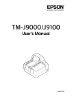
SUPERPOLE™ PLACEMENT
C
D
D
E
E
B
C
A
B
A
F
C
D
A
E
B
BEDROOM
BATHROOM
CHAIR
Locate pole adjacent to hip/belt line and
as close to bed as possible while
allowing clearance for bed coverings. If
using SuperBar™ option, you will need
to set the pivot locking positions of the
bar. As a suggestion, positions A and E
are good for moving in bed, B for pulling
up to sitting, C for pulling up to standing
and D for transferring out of bed.
TOILET and / or BATHTUB
Locate pole three to ten inches forward
of the knees, and two to six inches to
side of knees when seated.
BATHTUB ONLY
Locate pole base against tub,
approximately half way along its length.
If using SuperBar™ option, you will
need to set the pivot locking positions of
the bar. As a suggestion, positions B or
D are suitable for standing from toilet, C
and F for transferring into bathtub, E
and D for transferring out of bathtub.
Locate pole three to ten inches forward
of the knees, and two to six inches to
side of knees when seated. If using
SuperBar™ option, you will need to set
the pivot locking positions of the bar. As
a suggestion, positions A or C are
suitable for standing assistance, while
D and E are suitable for completing a
transfer to a nearby walker or
wheelchair. Position B provides side
support if this is preferred for standing.
HealthCraft Products Inc.,
2790 Fenton Road, Ottawa, Ontario, Canada, K1T 3T7.
DC100 REV D Page 3 of 12
Specifications subject to change without notice.
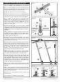
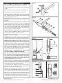
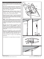
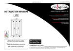
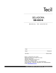
SUPERPOLE™ INSTALLATION INSTRUCTIONS
Figure 1.
4
Prior to installing the SuperPole™, we strongly
recommend that you first read through these instructions.
1
A1. Unpack the top plate (1) from the rectangular box, and
the pole assembly (2) from the cardboard tube (remove
staples to avoid scratching the paint on the pole).
5
3
A2. Remove the clevis pin (3) from the top plate (1).
2
A3. Align the locking pin holes of the pole and the top plate.
Insert the clevis pin (3) removed in step A1, and secure with
nylon washer (4) and cotter pin (5) as shown in Figure 1.
A4. To prepare, turn the extension screw (8) until the
distance from the top plate (1) to the bottom of the
extension screw is about two inches less than the actual
floor to ceiling height as shown in Figure 2a. You may
need to turn the jam nut (9) downward to allow the
extension screw to rotate.
A5. Place the base plate (7) on the floor at the intended
location of the pole. Move the pole into position as shown
in Figure 2b. Insert the stem at the bottom of the extension
screw (8) into the hole of the base plate (7) as shown in
Figure 2c.
HINT - It is easier to swing the pole up from the side of the
top plate as shown in Figure 3. If the top plate hits the
ceiling prior to reaching vertical you will need to shorten
the length of the extension screw.
A6. Set the pole to a true vertical position. This may be
done using a construction level, plumb bob, or by visually
comparing the pole with other vertical line features in the
room such as wall corners, etc.
Figure 2a.
Figure 2b.
6
8
9
LOWER POLE
RAISE POLE
TURN SCREW
COUNTER
CLOCKWISE
(CCW)
7
TURN SCREW
CLOCKWISE (CW)
Figure 2c.
Figure 3.
A7. While the cover sleeve (6) is held up, insert a bar such
as the shaft of a screwdriver, through the drive hole at the
bottom of the extension screw. Turn the extension screw
(Clockwise - CW) as shown in step 1 of Figure 4 to make
the top plate contact the ceiling. Continue turning the
extension screw approximately two to five turns until the
pole is secure and ready for testing in step A8.
Incorrect!
Correct!
Level
NOTE: The top plate must contact the ceiling squarely.
This can be facilitated by having a second person hold the
pole vertical while another turns the extension screw.
A8. Test the pole by firmly holding it at mid-height and
vigorously attempting to force the pole from side to side.
Use considerable body weight momentum to conduct an
aggressive test. If either the base, or the top plate appear
to slide or shift, reset the pole to vertical, tighten the
extension screw up to one more turn and repeat the test
until the pole will not move during this test.
6
A9. Turn jam nut (9) counter clockwise (CCW) to make
contact with the bottom of the pole as shown in step 2 of
Figure 4.
A10. Lock the extension screw by simultaneously turning
jam nut (9) and extension screw (8) counterclockwise until
jammed tight (as shown in step 3 of Figure 4). When finally
tight, remove the turning rod.
A11. Slide the cover sleeve (6) down to cover the
extension screw.
Figure 4.
(1)
(2)
CW
9
(3)
CCW
CCW
8
CCW
Your SuperPole™ installation is now complete.
HealthCraft Products Inc.,
2790 Fenton Road, Ottawa, Ontario, Canada, K1T 3T7.
DC100 REV D Page 4 of 12
Specifications subject to change without notice.
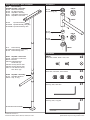
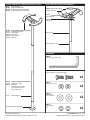
SP-P: SUPERPOLE™
SP403 / HD / HDU: TOP PLATE ASSEMBLY
SP-P
SP-BX
SP402
SP403
SP500
SP117 Top Rubber
Pole Assembly
Pole Parts Box
Base Plate Assembly
Top Plate Assembly
SuperPole™ Parts Pack
HW318 Nylon Washer
SP403
Top Plate Assembly
SP403HD Top Plate Assembly, Heavy Duty
SP403HDU Top Plate Assembly, Ultra
HW302 Clevis Pin
SP115 / HD / HDU
Top Plate / Heavy Duty / Ultra
HW323 Cotter Pin
SP-P / HD / HDU: POLE ASSEMBLY
SP-P
Pole Assembly
SP-PHD Pole Assembly, Heavy Duty
SP-PU Pole Assembly, Ultra
SP400
Pole with Grip
SP113 / HD / HDU Pole / Heavy Duty / Ultra
GR101
Grip, 20" Length
SP500 SuperPole™ Parts Pack
DC100 SuperPole™ Instructions
MK100 Brochure
SP114 Plastic Cover Sleeve
SP105
Threaded Collar
SP105HD Threaded Collar, Heavy Duty
SP105HDU Threaded Collar, Ultra
SP172 Jam Nut
SP107 Extension Screw
SP145 Plastic Washer
SP402: BASE PLATE ASSEMBLY
SP112 Base Plate
SP402 Base Plate Assembly
SP118 Base Plate Rubber
HealthCraft Products Inc.,
2790 Fenton Road, Ottawa, Ontario, Canada, K1T 3T7.
DC100 REV D Page 5 of 12
Specifications subject to change without notice.
SUPERBAR™ INSTALLATION INSTRUCTIONS
Figure 5.
Prior to installing the SuperPole™ with SuperBar™, we
recommend that you first read through these instructions.
13
B1. Complete steps A1 to A3 on page 4, and then continue with
step B2.
12
B2. Remove the cover sleeve (6) from the pole assembly (2).
B3. Unpack the contents of the SuperBar™ parts box.
11
10
B4. Using the small hex key wrench (11) and a countersunk
screw (12), attach one white plastic pivot bushing (13) to the
T-bar assembly as shown in Figure 5. Set aside the other
plastic pivot bushing and screw.
B5. Slide the spring collar (17) upwards on the castellated collar
(14) assembly to gain access to the set screws as shown in
Figure 8a.
Figure 6.
2
13
B6. Remove the three set screws (15) from the castellated collar
(14) using the large hex key wrench (16) as shown in Figure 8a.
10
17
14
B7. Slide the items (in order below and as shown in Figure 6)
onto the pole as straight as possible to avoid scratching the
pole: pivot bushing (13) bolted inside T-bar assembly (10),
spring collar (17) with castellated collar (14), pivot bushing (13)
and cover sleeve (6) removed in step B2.
13
6
B8. The SuperPole™ installation must be completed before
continuing with the SuperBar™ installation. Complete steps A4
to A10 on page 4, and then continue with step B9.
B9. Determine the desired height and locking positions of the
SuperBar™ as shown in Figure 7.
Height of T-bar: The height at which the castellated collar is
secured will determine the T-bar assembly height. Consider the
optimal height (H) of the bar from sitting and standing positions.
Figure 7.
2
Rotational Locking Positions of T-bar: Each groove on the
castellated collar corresponds to a rotational locking position for
the T-bar assembly. Fix the grooves to have the T-bar assembly
lock where required as discussed on page 3 ("Getting Started").
4
We recommend a placement test (lightly installing only one set
screw) to hold the castellated collar in place to verify the
settings are suitable. With this one screw in place, lower the
T-bar assembly onto the castellated collar, gently engage the
lock and verify if the bar is in the correct location.
14
ENSURE HEIGHT / ORIENTATION OF CASTELLATED
COLLAR IS CORRECT BEFORE PROCEEDING.
B10. With the castellated collar (14) in the desired location,
insert and tighten the three set screws (15) with the larger hex
key wrench (16) as shown in Figure 8a. When tightening, the
cone points of the set screws will penetrate the pole (leaving
permanent indentations) as shown in Figure 8b. The set
screws MUST be tightened until the back end of the screw
is flush with the collar or injury may result.
• Should you need to change the position of the height/angle
setting, we recommend that you change the height by at least
one inch. This will avoid set screw indentations from being too
close to each other, thereby weakening the pole.
• For the SuperPole™ Bariatric, you may notice it requires a
great deal of effort to screw in these fasteners. This is due to the
thicker gauge of steel used to make the pole.
B11. Slide the spring collar (17) downward on the castellated
collar (14) as shown in Figure 8a to retain set screws (15) while in
service. Inspect frequently to ensure screws and collar are tight.
B12. Lower the T-bar assembly onto the castellated collar and
install the remaining white plastic pivot bushing (13), securing it with
the countersunk screw (12) using the small hex key wrench (11).
Your SuperPole™ with SuperBar™ installation is now complete.
HealthCraft Products Inc.,
2790 Fenton Road, Ottawa, Ontario, Canada, K1T 3T7.
H
Top View
6
7
8
5
1
4
Figure 8a.
3
2
Figure 8b.
17
Incorrect!
14
15
16
2
Correct!
DC100 REV D Page 6 of 12
Specifications subject to change without notice.
SPB-S: SUPERPOLE™ WITH SUPERBAR™
SP-P
SPB-BX
SP402
SP403
SP404
SP411
SP501
Pole Assembly
SuperBar™ Parts Box
Base Plate Assembly
Top Plate Assembly
SuperBar™ Assembly
Castellated Collar Assembly
SuperBar™ Parts Pack
SUPERBAR™
HW100
SP102
Pivot Bushing (x2)
HW300
SP403
Top Plate Assembly
SP403HD Top Plate Assembly, Heavy Duty
SP403HDU Top Plate Assembly, Ultra
SP170
Spring Ring
HW112
SP106
Castellated Collar
HW320
SP-P
Pole Assembly
SP-PHD Pole Assembly, Heavy Duty
SP-PU Pole Assembly, Ultra
HARDWARE
SuperBar™ Parts Pack
SuperPole™ Instructions
Brochure
FHSCS #8-32x⅜"
S/S Screws (x2)
HW 300 Hex Key Wrench 3/32"
HW 320 Hex Key Wrench 5/32"
HW 112 Cone Point Set Screw,
5/16”-24x⅜" (x4)
SP501
DC100
MK100
HW 100
HW100
Set Screw, FHSCS, #8-32 x .375", S/S
x2
HW112
Set Screw, Cone Point, 5/16"-24x3/8"
x3
HW300
Hex-Key, 3/32", Short Arm
x1
HW320
Hex-Key, 5/32", Long Arm
x1
SP404 SuperBar™ Assembly
SP116 SuperBar Weldment
GR100 Grip, 16” long
SP402 Base Plate Assembly
*not to scale
HealthCraft Products Inc.,
2790 Fenton Road, Ottawa, Ontario, Canada, K1T 3T7.
DC100 REV D Page 7 of 12
Specifications subject to change without notice.
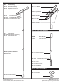
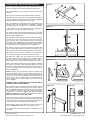
SUPERTRAPEZE™ INSTALLATION INSTRUCTIONS
Figure 9.
2
Prior to installing the SuperPole™ with SuperTrapeze™, we
recommend that you first read through these instructions.
17
C1. Complete step A1 to A2 on page 4, and then continue with
step C2.
21
C2. Unpack the contents of the SuperTrapeze™ parts box.
20
C3. Slide the support arm (20) onto the top of the pole with the
strap hook facing towards the grip (21) as shown in Figure 9.
Rest the support arm against the top of the grip.
C4. The SuperPole™ installation must be completed before
continuing with the SuperTrapeze™ installation. Complete
steps A3 through A11 on page 4, then continue with step C5.
Figure 10.
• See pages 2-3 for recommendations on “SuperPole™
Placement” and “Patient Entrapment Warnings”.
C5. Hold the trapeze handle under the support arm, such that
the shorter rail (23) of the handle is closest to the head of the
bed as shown in Figure 10.
C6. Facing the foot of the bed, rotate the strap 180 degrees
(away from the rail), open the loop on the end of the strap
(22), and slide it on to the shorter rail (23) of the trapeze
handle as shown in Figure 11. Slide it past the grip and along
the trapeze tube until it reaches the top bend of the trapeze.
The handle will now be hanging as shown in Figure 10.
23
84"
C7. Have the user lie on the bed and place their hands palm
down on their thighs. Rotate the support arm around the pole
until the trapeze handle hangs directly above the user’s hands.
C8. Slide the spring collar (17) upwards on the support arm
(14) assembly to gain access to the threaded holes (x3).
C9. Raise the support arm (20) straight up the pole. We
recommend the top of the support arm be installed approx.
84" from the floor. Have someone hold it here for a test, or
lightly install one set screw to hold the support arm in place.
Figure 11.
C10. Set the trapeze handle to the proper height by adjusting
the length of the strap. When adjusted properly, the users
fingers should be able to comfortably grasp around the bottom
rail of the trapeze handle when lying down on the bed, as
shown in Figure 10.
22
TEST: Have the user go through the motions of sitting up in
bed (as the support arm is not completely installed, do not
exert full weight on trapeze handle). If the trapeze handle is
too close or too far away for suitable support, remove the set
screw, turn the arm to a better location, and reinstall the set
screw. Gently retry the trapeze again, and repeat until the
user is satisfied.
TOP
BEND
23
ENSURE HEIGHT / ORIENTATION OF SUPPORT ARM IS
CORRECT BEFORE PROCEEDING.
C11. With the support arm (20) in the desired location, tighten
the three set screws (25) with the hex key wrench (24) as
shown in Figure 12a. When tightening, the cone points of the
set screws will penetrate the pole (leaving permanent
indentations) as shown in Figure 12b. The set screws
MUST be tightened until the back end of the screw is
flush with the collar or injury may result.
• Should you need to change the position of the height/angle
setting, we recommend that you change the height by at least
one inch. This will avoid set screw indentations from being too
close to each other and thereby weakening the pole.
Figure 12a.
Figure 12b.
26
Incorrect!
25
24
C12. Slide the spring collar (26) down over the screws, as
shown in Figure 12a. Failure do so may result in injury.
Your SuperPole™ with SuperTrapeze™ installation is now
complete.
HealthCraft Products Inc.,
2790 Fenton Road, Ottawa, Ontario, Canada, K1T 3T7.
Correct!
DC100 REV D Page 8 of 12
Specifications subject to change without notice.
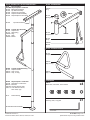
STP-S: SUPERPOLE™ WITH SUPERTRAPEZE™
SP-P
STP-BX
SP402
SP403
SP408
SP409
SP505
SP403
SP408
SP123
SP170
HW500
SP125
HW305
Pole Assembly
SuperTrapeze™ Parts Box
Base Plate Assembly
Top Plate Assembly
Trapeze Arm Assembly
Trapeze Handle Assembly
SuperTrapeze™ Parts Pack
SP408: TRAPEZE ARM
HW500
Plug
HW112
SP170
Spring Ring
Top Plate Assembly
Trapeze Arm Assembly
Trapeze Arm
Spring Ring
Plug
Strap
Buckle
SP123
Trapeze Arm
HW320
SP125
Strap
HW305
Buckle
SP409: TRAPEZE HANDLE
SP124
Trapeze Handle
GR102
Grip, 6" long
SP409
SP124
GR102
GR103
Trapeze HandleAssembly
Trapeze Handle
Grip, 6" long
Grip, 10" long
SP505
DC100
MK100
HW 320
HW 112
SuperTrapeze™ Parts Pack
SuperPole™ Instructions
Brochure
Hex Key Wrench 5/32"
Cone Point Set Screw,
5/16"-24x⅜" (x4)
SP-P
Pole Assembly
GR103
Grip, 10" long
HARDWARE
HW112
Set Screw, Cone Point, 5/16"-24x3/8"
x4
HW320
Hex-Key, 5/32", Long Arm
x1
SP402 Base Plate Assembly
*not to scale
HealthCraft Products Inc.,
2790 Fenton Road, Ottawa, Ontario, Canada, K1T 3T7.
DC100 REV D Page 9 of 12
Specifications subject to change without notice.
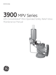
ANGLED CEILING PLATE INSTALLATION INSTRUCTIONS
Figure 1.
Joist
Prior to installing the SuperPole™ with Angled Ceiling
Plate, we recommend that you first read through these
instructions.
Ceiling
D1. Unpack the angled ceiling plate (27) from the box,
and the pole assembly (2) from the cardboard tube
(remove staples to avoid scratching the paint on the
pole). Remove the clevis pin (28) from the pivoting
bracket of the angled ceiling plate.
27
Wood Screw (x4)
D2. Determine the location of the pole. Secure the
angled ceiling plate to the ceiling, making sure that it is
fastened to the ceiling joists with appropriate wood
screws (min #10 x 2-1/2”) as shown in Figure 1.
28
29
30
D3. Slide the top end of the pole (2) onto the pivoting
bracket as shown in Figure 1. Align the locking pin
holes of the pole and the bracket. Insert the clevis pin
(28) removed in step D1, and secure with nylon washer
(29) and hitch pin (30).
HINT - Set the extension screw (8) such that the
distance from the angled ceiling plate (27) to the bottom
of the extension screw is about two inches less than the
actual floor to ceiling height. You may need to unscrew
the jam nut (9) downward to allow the extension screw
to rotate.
D4. Place the circular base (7) on the floor at the
intended location of the SuperPole™. Set the
SuperPole™ to a true vertical position as shown in
Figure 2. This may be facilitated using a construction
level, plumb bob, or by visually comparing the pole with
other vertical line features in the room such as wall
corners, etc.
2
Figure 2.
Incorrect!
Level
D5. Once the SuperPole™ is set to a true vertical
position, lock the angle of the pivoting bracket on both
sides with the supplied hardware. Refer to Figure 3 for
correct configuration: bolt (31), flat washer (32), split
washer (33) and nut (34). Tighten with hex key (35).
6
8
7
Continue with step A7 on page 4 of the SuperPole™
instructions.
Your SuperPole™ for Angled Ceiling is now installed.
9
Figure 3.
32
33
31
34
35
HealthCraft Products Inc.,
2790 Fenton Road, Ottawa, Ontario, Canada, K1T 3T7.
DC100 REV D Page 10 of 12
Specifications subject to change without notice.
SP-ACP: SUPERPOLE™ WITH ANGLED CEILING PLATE
SP-P
SP402
SP198
SP 513
Pole Assembly
Base Plate Assembly
Angled Ceiling Plate Assembly
Angle Ceiling Plate Parts Pack
POLE / ANGLED CEILING PLATE ASSEMBLY
SP198 Angled Ceiling Plate
HW323 Hitch Pin
HW318
Nylon Washer
HW302
Clevis Pin
SP198
SP115
SP194
HW302
HW318
HW323
Ceiling Anchor Plate Assembly
Angled Ceiling Plate
Top Rubber
Clevis Pin
Nylon Washer
Hitch Pin
SP113 Pole
GR101 Grip, 20" long
HARDWARE
HW322
Hex Key, 5/32", Short Arm
HW151
Screw, SHCH, 1/4-20 x 5/8" Length
x2
SP513 Angle Ceiling Plate Parts Pack
DC100 Instructions, ACP
MK104 Brochure
Hex Key Wrench 5/32"
Cone Point Set Screw,
5/16"-24x⅜" (x4)
SP-P
Pole Assembly
SP402 Base Plate Assembly
HealthCraft Products Inc.,
2790 Fenton Road, Ottawa, Ontario, Canada, K1T 3T7.
HW161
Nut, Nylock, 1/4-20
x2
HW154
Flat Washer
1/4" x 5/8" OD
HW155
Split Washer
1/4"
x2
x2
DC100 REV D Page 11 of 12
Specifications subject to change without notice.
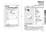
SuperPole™ Solutions
for Ceiling Challenges
Each Sold Separately. See Product Compatability Chart on Page 2.
Solutions for Ceiling Height Challenges
Structural Ceiling
Structural Ceiling
Uni-Fit
Extender™
Structural Ceiling
SuperPole™
(90"/229cm)
SuperPole™
(90"/229cm)
Ultra
SuperPole™
(103"/262cm)
Floor to
Ceiling Range:
Floor to
Ceiling Range:
Floor to
Ceiling Range:
93-99" /
236-251cm
100-120" /
254-305cm
121-140" /
307-356cm
Custom cut
Extension Tube
SuperPole™ (SP-S)
Uni-Fit Extender™ (SP-UF)
SuperPole™ Ultra (SP-ULTRA)
A floor to ceiling pole that expands between the
floor and ceiling (up to 8 feet) to create
unparalleled sturdiness and reliability.
An extension tube that mounts to the top of the
SuperPole™ to increase the floor to ceiling
range up to 10 feet.
A longer SuperPole™ used with a custom cut
extension tube to increase the floor to ceiling
range up to 11.5 feet.
Solutions for Ceiling Construction Challenges
Structural
Ceiling
Joist
* REQUIRED FOR
ANGLED
CEILINGS
24"
Ceiling
Ceiling Plate
Extender™
Standard
Top Plate
Pole
Angled Ceiling Plate (see Page 10)
Ceiling Plate Extender™
A circular top plate that replaces the standard top plate to allow a
SuperPole™ to be installed in rooms with angled ceilings. Adjustable
from 0-45 degrees. Screws into the ceiling.
An extension plate that increases the span of the standard SuperPole™
top plate from 20" to 30". Ideal where ceiling joists have increased
spacing (such as 24" between centers).
HealthCraft Products Inc.,
2790 Fenton Road, Ottawa, Ontario, Canada, K1T 3T7.
DC100 REV D Page 12 of 12
Specifications subject to change without notice.