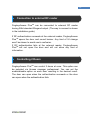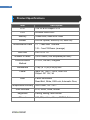
1
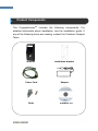
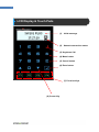
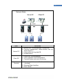
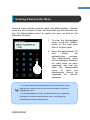
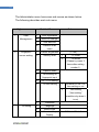
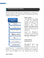
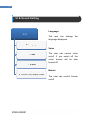
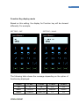
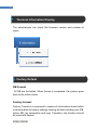
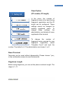
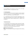
© Copyright 2009, NITGEN&COMPANY Co., Ltd.
All rights reserved.
•
`
•
Unauthorized reproduction of part or all of this manual’s content in any form is
prohibited.
Product specifications may change without prior notice to improve functionality.
NITGEN&COMPANY the NITGEN logo are registered trademarks of
NITGEN&COMPANY
Other names and trademarks belong to respective companies.
•
The font used in this product is Naver’s “Nanum”.
•
•
NITGEN&COMPANY Customer Service Center
Tel: +82.2.513.2150
Fax: +82.2.513.2191
Email: [email protected]
3
Table of Contents
CHAPTER 1 GETTING STARTED ........................................... 4
PRODUCT COMPONENT ......................................................................................... 5
PRODUCT DESCRIPTION ........................................................................................ 6
LCD DISPLAY & TOUCH PADS ............................................................................... 7
FINGERPRINT READING ......................................................................................... 8
SYSTEM CONFIGURATION ...................................................................................... 9
CHAPTER 2 ADMINISTRATOR MENU .................................. 11
ENTERING ADMINISTRATOR MENU ....................................................................... 12
USER MANAGEMENT ........................................................................................... 16
FINGERPRINT SENSOR SETTING ........................................................................... 17
UI & SOUND SETTING ......................................................................................... 19
SYSTEM SETTING................................................................................................ 21
NETWORK SETTING............................................................................................. 23
TERMINAL INFORMATION DISPLAY ........................................................................ 25
FACTORY DEFAULT ............................................................................................. 25
USB .................................................................................................................. 27
CHAPTER 3 GENERAL USER .............................................. 29
DOOR OPENING .................................................................................................. 30
AUTHENTICATION IN ATTENDANCE MODE.............................................................. 32
CHANGING USER INFORMATION ........................................................................... 33
USING KEYPHONE .............................................................................................. 34
APPENDIX........................................................................ 35
TROUBLESHOOTING ............................................................................................ 36
CONNECTION TO EXTERNAL RF READER .............................................................. 38
CONTROLLING 2 DOORS ..................................................................................... 38
PRODUCT SPECIFICATIONS .................................................................................. 39
4
Chapter 1
Getting Started
Product Components
Product Description
LCD Display & Touchpad
Fingerprint Reading
System Configuration
-5
-6
-7
-8
-9
5
Product Components
The FingkeyAccessTM includes the following components. For
detailed information about installation, see the installation guide. If
any of the following items are missing, contact the Customer Support
Team.
Terminal
Power Cord
Bolts
Installation Bracket
Adapter
Software CD
6
Product Description
(1) LCD
.
(2) Reset Button
(3) USB
(4) Touch Button
(5) Fingerprint Input
(6) Card Input
No.
Name
Description
1
LCD
Displays information to the user.
2
Reset Button
Used to reset the device.
3
USB
Data can be uploaded via USB memory stick.
4
Touch Panel
Information input via touch sensitive panel.
5
Fingerprint
The user places his/her finger for authentication.
Input
6
Card Input
The user places his/her card for authentication.
7
LCD Display & Touch Pads
(1)
Initial message
(2)
Network connection status
(3) Keyphone Call
(4) Menu button
(5) Cancel button
(6) Enter button
(7) Function Keys
(8) Cursor Key
8
Fingerprint Reading
Scan fingerprints as described below for fingerprint registration and
authentication to prevent authentication errors.
① Maximize the finger area scanned by pressing evenly against
the reader. (70 ~ 80% of full pressure).
② Place the “core” of the fingerprint at the center of the scanner.
The core is usually opposite the whitish half-moon on the bottom
of the fingernail. Therefore, place the half-moon part at the
center of the scanner when scanning.
Correct
Incorrect
9
System Configuration
The Access Control Terminal (FingkeyAccess PlusTM) can function
either in the network or Stand-alone mode. In Stand-alone mode, all
functions are available and the terminal does not need to be
connected to the network. In network mode, multiple terminals are
connected to the server through TCP/IP links and the terminals can
be managed by the administrator.
To use FingkeyAccess PlusTM in Network mode, a server and a
management program (AccessManager Professional) must be
installed.
Stand-alone Mode
10
Network Mode
Server PC
Client PC
TCP/IP
Item
Functions
Server PC
1. Server S/W : AccessManager Professional
2. Terminal management, communication and log
data collection
3. User profile and log data DB
4. Authentication
Client PC
1. Client S/W: AccessManager
2. User registration and management
3. Terminal status and event monitoring
Terminal
1. User registration, modification, deletion and
checking
2. Warning/Alarm handling
3. Door control
11
Chapter 2
Administrator menu
Entering Administrator Menu
- 12
User Management
- 16
Fingerprint Sensor Setting
- 17
UI & Sound Setting
- 19
System Setting
- 21
Network Setting
- 23
Terminal Information Display
- 25
Factory Default
- 25
USB
- 27
12
Entering Administrator Menu
Terminal users include general users and administrators. General
users are only allowed to open the door while the administrator can
use the Administrator menu to control the door as well as the
terminal’s functions.
1. To enter the Administrator
menu, touch the “MENU”
button on the right hand
side of the touch pad.
2.
Input the administrator ID
and
follow
the
authentication
process.
The Administrator menu
will be displayed. Because
no users have yet been
registered, any user can
enter the Administrator
menu.
At
least
one
administrator should be
registered
for
security
purposes.
1. If no administrator was designated and only general users were
registered in network mode, all users will be allowed to enter the
Management menu.
2. If 1:N authentication is used, an administrator with a registered
fingerprint can enter the Administrator menu using fingerprint
authentication without entering his ID.
13
The Administrator menu has seven sub menus as shown below.
The following describes each sub menu:
Higher menu
1
Detailed Menu
User
1
User registration
Management
2
User info change
3
User deletion
4
Deletion of all
Fingerprint
1
Sensor brightness
sensor setting
2
Security level
Sub menu
users
2
(1~100)
1
2
1:1 mode
1:N mode
(Please try menu 3
times after setting
number 1)
3
Capture mode
4
Time setting for
5
AUTO-ON setting
6
1:N time setting
fingerprint input
1
Whether to use 1:N
time setting or not
2
Time setting
(“time setting”
possible only when it
is on)
3
UI setting
7
FreeScan
1
Language
2
Button tone
3
Function Key
Display
Off/Mode1/Mode2
14
4
System Setting
1
Log storing
2
RF card
OFF
HID
MIFARE
EM
iCLASS
CEPAS/Felica
3
4
WIEGAND
Function key
1
OFF
2
26BIT
3
34BIT
Auto T&A / Muti T&A
setting
5
Authentication
mode
5
Network
6
Time setting
7
Terminal mode
8
Time zone
1
Terminal ID
2
TCP/IP
(1-2000)
1
DHCP yes or
2
Terminal IP
3
Subnet Mask
no?
6
7
Information
Factory default
3
Time limit
4
Port setting
1
Number of users
2
Firmware version
1
DB Format
2
Factory format
4
Gateway
5
Server IP
15
3
Number of
registered
fingerprints
4
Number of
characters in ID
5
8
USB
Reset terminal
1
User Download
2
All user download
3
Log download
4
All user upload
5
FW update
16
User Management
The administrator can register, delete and change users with the
User menu.
User Registration
The maximum number of users
that can be registered is 1,000.
(2,000 templates)
User Change
User IDs are unique and cannot
be changed. However, group,
privilege,
fingerprint,
and
authentication type can be
changed in the “Modify” menu.
Users can only be changed in
Stand-alone mode. In Network
mode, the server management
program must be used to change
users.
User Deletion
In Network mode, the User menu does not support deletion of certain
or all users. The administrator can only delete all users registered at
a certain terminal by selecting “Reset Æ User Data.”
17
Fingerprint Sensor Setting
Settings related to fingerprint sensor options such as security level,
fingerprint capture time, capture mode, LFD precision, and sensor
brightness can be configured.
Sensor Option
If the fingerprint is too bright
or dark, the brightness,
contrast, and gain can be
adjusted. In 1:N mode, the
terminal’s
basic
sensor
settings will be applied even
though individual sensor
options were set during user
registration.
Select
the
“Brightness”,
“Contrast”, or “Gain” tab, and
select the value by moving
your finger on the slider.
Authentication
Security Level
The security level is set
according
to
the
authentication method. The
security level for 1:1 authentication is between 1 and 9, and the
default is 5. The security level for 1:N authentication is between 5
and 9, and the default is 8. If the security level is too high,
18
authentication failure rate may rise, and if it security level is too low,
the misreading rate may rise. Therefore, the default level should be
used. This level applies to all users except those who chose different
security levels when registering.
Capture Mode
Set whether to distinguish fake fingerprints, to what degree of
precision. “Low”, “High”, or “Not in Use” are available.
Authentication Limit Time
The fingerprint input waiting time is between 3 and 9 seconds, and
the default is 5 seconds.
Auto-On Setting
1:N Authentication Time
If 1:N authentication is being used, the time can be set during which
all user fingerprints are searched. The input value can be between
three to nine seconds, with the default being three seconds. If the
search fails after the specified time, a “Matching timeout” error will
occur.
19
UI & Sound Setting
Language
The user can change the
language displayed.
Voice
The user can control voice
on/off. If you select off the
voice, buzzer will be also
turned off .
Buzzer
The user can control buzzer
on/off.
20
Function Key display mode
Based on this setting, the display for Function key will be showed
differently. For example,
SETTING = OFF
SETTING = Mode2
The following table shows the message depending on the option of
function key displayed:
Option
F1 KEY
F2 KEY
F3 KEY
F4 KEY
Off
F1
F2
F3
F4
Mode1
Clock In
Clock Out
Absence
Return
Mode2
Check In
Check Out
F3
F4
21
System Setting
Settings related to the system such as log storing, RF card, Wiegand,
Function key, time, terminal mode and timezone.
Saving Logs
The administrator can save logs
that
arise
during
user
authentication. To save logs,
select “Save Logs” and change
“No” to “Yes.”
The logs can be checked by
selecting “Info” Æ “Log”, or by
using
the
“AccessManager
Professional” program.
RF Card
To use card authentication to
authenticate users, do the
following. Select the card type –
MIFARE, HID, EM, iCLASS,
CEPAS.
Please note: If you select CEPAS,
access also works for Felica
cards.
22
Wiegand
Decides whether or not to use Wiegand communication protocol to
send authentication results and user ID to a server.
Function Mode (Time and Attendance mode)
Time and attendance mode; the user must press a function key and
perform the user authentication process when opening the door. The
entry logs will be sent with the function key data to the server
management program.
Depending on the function key, user attendance records can be
classified into the following: “Coming to work”, “Leaving work”,
“Going out”, and “Returning” enabling efficient attendance
management.
Auth Mode
NL: Network mode. In this mode, the terminal connects to Access
Server ProfessionalTM via TCP/IP network.
SO: Standalone mode. The terminal works standalone without
Access Server ProfessionalTM.
Time Setting
Adjust to set the time on the device.
Terminal Mode (wiegand output)
You can choose to select Wiegand output.
When ‘Reader’ is selected, Wiegand output will be the RF card
number. When ‘Terminal’ is selected, Wiegand output will be
Facility code and User ID.
23
Time Zone
The “Time Zone” menu is used to restrict or allow entry during certain
time periods. Activate this by enabling or disabling this function.
Network Setting
The FingkeyAccessTM terminal can function either in Network or
Stand-alone mode. Wireline networks are supported in the Network
mode. If the DHCP option is deactivated, the terminal IP, subnet
mask, and gateway must be
inputted manually. For more
information, contact the service
team.
Terminal ID
Enter a unique terminal ID between
1 and 2000. The same terminal ID
cannot be used in the same server.
TCP/IP Setting
After selecting network mode,
TCP/IP must be configured to
connect to the server.
Press “on” in the “DHCP” menu to
use DHCP. When using DHCP, enter the server IP and port
information of the server with AccessManager Professional installed.
24
N/W Timeout (Time Limit)
The amount of time before the ‘Timeout’ becomes active. Don’t set
this value too short.
Port Number Setting
Enter the port number to be used for communication between the
server and the terminal. The default value is “7332” and the user can
choose between 2000 and 65535. When changing the port data in
the terminal, change the communication setting of AccessManager
Professional accordingly.
What is DHCP (Dynamic Host Configuration Protocol)?
The DHCP server automatically allocates and manages settings for TCP/IP
communication. If DHCP is on, related information such as terminal IP,
subnet mask, and gateway are automatically allocated.
25
Terminal Information Display
The administrator can check the firmware version and number of
users.
Factory Default
DB Format
All DB are formatted. When format is completed, the system goes
back to the initial screen.
Factory Format
Factory Format is a command to restore all information stored within
a terminal back to factory settings clearing all data including user DB,
option DB, log information and logo. Therefore, the function should
be used with caution.
26
Fixed Option
(FP number, ID length)
In the menu, the number of
fingerprint scans to be input during
fingerprint registration and the ID
length can be configured. These
settings cannot be changed for
existing registered users. To
change
these
settings,
the
administrator must delete all users
registered at the terminal.
To change the number of
fingerprint scans required for user
fingerprint
registration,
select
“Template Count” and input the
number. The default is 2. The administrator can choose 1 or 2.
Reset Terminal
Terminals can be reset without disassembly. Please choose 『yes』
in the confirmation screen to reset the terminal.
Keyphone Length
Before using keyphone, you can set the phone number’s length. The
range is 1~11.
27
USB
FingkeyAccess PlusTM supports USB host function. This enables the
upload/download of user data from FingkeyAccess PlusTM via USB
memory stick. You can also get log event data from the terminal
and upgrade the Firmware.
User download
You can download the user you
want from the terminal to USB
memory stick. The data can be
registered to Access Manager
Professional or another terminal.
All user download
You can download all users in the
terminal to USB. User data file
name is named: “USERDATA.ndb”
Log download
All log data saved in the terminal
can be copied to USB. Access
manager professional can read and
manage the data. User data file
name is named: “USERDATA.ndb”
28
User upload
The user data in the USB can be uploaded to the terminal. You can
save the user data to USB using Access manager professional or
another terminal. Please note: Caution should taken when uploading
user data. If duplicate users are found, the upload of the existing
user will be excluded. Please ensure the User data file name is
named: “USERDATA.ndb” to upload.
FW Update
You can update the FW using USB. Please ensure the Firmware file
name is named: “SW101_FW.bin”. If not, the terminal will not accept
the update.
29
Chapter 3
General User
Door Opening
- 30
Authentication in Attendance Mode
- 32
Changing User Information
- 33
Using keyphone
- 34
30
Door Opening
A user registered at the terminal can open the door in two ways
depending on whether 1:N authentication is used.
1:1 Authentication
The user enters his ID and scans his fingerprint, and the scanned
fingerprint is compared 1:1 to the registered fingerprint that matches
the ID. This method allows for quick authentication.
In 1:1 authentication mode, the user selects “Authentication” on the
lower left, and enters his ID. Then, the user continues the
authentication process using the registered means – fingerprint, card,
or password.
1:N Authentication
In 1:N authentication, the user does not need to input his ID. Instead,
the scanned fingerprint is authenticated by searching all fingerprints
in the DB. The process is simpler than 1:1 authentication, however if
a large number of users exist this may take more time.
① Fingerprint Authentication
The user is authenticated by scanning his fingerprint without entering
his ID.
31
② Card Authentication
The user is authenticated only by scanning his card without entering
his ID.
If 1:N authentication is not activated, the user will be asked to input
his ID after he presses “Authentication” on the terminal.
In 1:N authentication, the password user is authenticated in
the same ways as in 1:1 authentication.
32
Authentication in Attendance Mode
In attendance mode, all users must press the functions keys in order
to be authenticated. All logs are transmitted to the server. If the users
do not press the function keys selecting the attendance type
(“Coming to work”, “Leaving work”, “Going out”, and “Returning”) they
may not be recorded. The user must select the appropriate function
key in order to be authenticated.
Using Attendance Mode
General/Simple
In attendance mode, function keys
are displayed on the lower-right of
the initial screen.
1.
In
Simple
or
General
Attendance mode, the user
must press a function key and
input his ID to be authenticated.
Function keys are as follows:
F1: Coming to work
F2: Leaving work
F3: Going out
F4: Returning
2. After the user selects a function
key, the key will be included in
the server log data which will be
used
by
the
attendance
management program.
33
Using Extended Attendance
Mode (Not available)
In Extended Attendance Mode, the
initial main screen will be displayed
as shown on the left.
1.
Select a function key, and press
arrow keys to change function
number.
2.
Enter the user ID and press
“Enter” to authenticate.
To use 1:N authentication in attendance mode, enter the
attendance key and perform authentication without inputting an ID.
Changing User Information
The administrator can change the passwords, fingerprints, and card
information of registered users using the terminal’s Administrator
menu or the server program. To change user information, contact the
administrator.
34
Using Keyphone
If you want to use the keyphone, touch the phone-icon. You can call
the intended person by entering the phone number. The recipient can
open the door by pushing the button [*]Æ[7]Æ[8]Æ[9] on his phone.
35
Appendix
Troubleshooting
- 36
Connection to external RF reader
- 38
Controlling 2 doors
- 38
Product Specifications
- 37
36
Troubleshooting
<If fingerprint authentication takes too long>
1. If the terminal uses 1:N authentication in network mode,
server overload may occur, resulting in slow authentication
and recognition. In this case, a dedicated server should be
used.
2. Check if the finger and the sensor are clean. Clean the finger
and the sensor. If the user’s fingerprint is in anyway
damaged, the user must register another fingerprint.
3. If the fingerprint is not clean, lower the security level of the
user and use the 1:1 authentication method.
4. Input the user’s ID in 1:1 mode and check if the user exists.
<If fingerprint is not registered>
If the finger is too dry or humid, fingerprint image quality may be
poor and may not register. Dry or moisturize the finger before
registering the fingerprint.
<If RF card authentication fails>
1. Check your RF card type matches with the RF option of
Terminal.
37
<If network connection cannot be established>
1. Check if the network setting is correct.
2. Check the TCP/IP setting.
① IP address of the server where AccessManager
Professional is installed.
② The server and the terminal must use the same port.
④ Related settings if DHCP is not used.
3. Synchronize the terminal and the server settings.
<If the door does not open after authentication>
1. Check the time period during which access is allowed.
2. Check JP1 jumper status is correct. (refer to install guide)
<If users cannot be registered>
In default configuration, this product operates in network mode
which requires a proper network connection for user registration.
Check the network connection, or disable network mode to not use
the network.
<If the product is unstable or does not function>
1. Reset via terminal by selecting “Menu” Æ “Reset” menu.
2. Restart the server if the server management program is in
use.
3. If the terminal buttons do not function, restart the terminal by
pushing external reset button located right side of terminal.
4. If the problem remains after the above actions are taken,
contact the Customer Support Team.
38
Connection to external RF reader
FingkeyAccess PlusTM can be connected to external RF reader
having 26bit standard Wiegand output. (The way to connect is shown
in the installation guide).
If RF authentication succeeds at the external reader, FingkeyAccess
PlusTM opens the door and sound buzzer. Any kind of UI change
won’t be shown to avoid user’s confusion.
If RF authentication fails at the external reader, FingkeyAccess
PlusTM will not open the door and will not show any kind of
information.
Controlling 2 Doors
FingkeyAccess PlusTM can control 2 doors at once. This option can
be selected via Access manager professional. You can set the
enable/disable option on each door resulting in the desired result.
The door can open when the authentication succeeds or the door
can open when the authentication fails.
39
Product Specifications
Item
LCD
Description
128*32 B/W Graphic STN
CPU
400MHz 32Bit RISC
Memory
16MB RAM, 8MB NOR Flash
Sensor
OPP06 Optical, 500DPI(LFD, Auto-On)
Authentication Rate
1:1 – Less than 1 second
1:N – 1sec/1000user (average)
FAR/FRR
0.001% /0.1%
Number of users
3,000 Users (Two templates per user)
Communication
Method
TCP/IP, RS-485, Wiegand
Dimensions
Power
Door
178(L) x 77(W) x 50(H) mm
Input: AC 100V ~ 240V, 50/60 Hz
Output: DC 12V, 3A
2 door controllers
Dead Bolt, Strike, EM Lock, Automatic Door,
Temperature/Humidity
User interface
Keyphone
RF card
IP65 Class, -20 ~ 60℃
LCD, touch, voice, buzzer
Calling, talking, door control
HID, EM, mifare, iClass, CEPAS, Felica
40
WARNING
This is a class A product. In a domestic environment this product may cause radio
interference in which case the user may be required to take adequate measures.
INFORMATION TO THE USER (15.105(a))
For Class A digital device
INFORMATION TO THE USER
This equipment has been tested and found to comply with the
limits for a Class A digital device, pursuant to part 15 of the
FCC Rules. These limits are designed to provide reasonable
protection against harmful interference when the equipment is
operated in a commercial environment. This equipment
generates, uses, and can radiate radio frequency energy, and
if not installed and used in accordance with the instruction
manual, may cause harmful interference to radio
communications. Operation of this equipment in a residential
area is likely to cause harmful interference in which case the
user will be required to correct the interference at his own
expense.
WARNING
(Part 15.21)
Any changes or modifications not expressly approved by the
manufacturer could void the user’s authority to operate the
equipment.