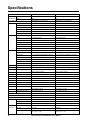
1
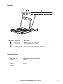
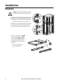
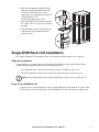
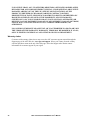
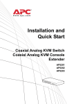
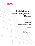
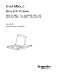
User’s Manual Rack LCD Console KVM Switch AP5808 AP5816 This manual is available in English on the enclosed CD. Dieses Handbuch ist in Deutsch auf der beiliegenden CD-ROM verfügbar. Este manual está disponible en español en el CD-ROM adjunto. Ce manuel est disponible en français sur le CD-ROM ci-inclus. Данное руководство на русском языке имеется на прилагаемом компакт-диске. 您可以从包含的 CD 上获得本手册的中文版本。 동봉된 CD 안에 한국어 매뉴얼이 있습니다 . Contents General Information ........................................................ 1 Overview . . . . . . . . . . . . . . . . . . . . . . . . . . . . . . . . . . . . . . . . . . . . . . . . 1 Symbols used in this manual . . . . . . . . . . . . . . . . . . . . . . . . . . . . . . 1 Cross-reference symbol used in this manual . . . . . . . . . . . . . . . . . 1 Safety . . . . . . . . . . . . . . . . . . . . . . . . . . . . . . . . . . . . . . . . . . . . . . . . . . . 2 Components . . . . . . . . . . . . . . . . . . . . . . . . . . . . . . . . . . . . . . . . . . . . . 3 Front View . . . . . . . . . . . . . . . . . . . . . . . . . . . . . . . . . . . . . . . . . . . . . . 3 Rear View . . . . . . . . . . . . . . . . . . . . . . . . . . . . . . . . . . . . . . . . . . . . . . . 5 Compatible Cables . . . . . . . . . . . . . . . . . . . . . . . . . . . . . . . . . . . . . . . 5 Installation ....................................................................... 6 Brackets . . . . . . . . . . . . . . . . . . . . . . . . . . . . . . . . . . . . . . . . . . . . . . . . . 6 Single KVM Rack LCD Installation . . . . . . . . . . . . . . . . . . . . . . . . . . . 7 KVM cable installations . . . . . . . . . . . . . . . . . . . . . . . . . . . . . . . . . . . 7 Power On the KVM Rack LCD . . . . . . . . . . . . . . . . . . . . . . . . . . . . . . 7 Multiple KVM Switches Installed in Series . . . . . . . . . . . . . . . . . . . . . 8 Installation . . . . . . . . . . . . . . . . . . . . . . . . . . . . . . . . . . . . . . . . . . . . . . 8 Server connections . . . . . . . . . . . . . . . . . . . . . . . . . . . . . . . . . . . . . . 8 Power On the KVM Rack LCD and KVM switches . . . . . . . . . . . . . . 8 Operation ......................................................................... 9 Basic Functions . . . . . . . . . . . . . . . . . . . . . . . . . . . . . . . . . . . . . . . . . . 9 Opening the KVM Rack LCD . . . . . . . . . . . . . . . . . . . . . . . . . . . . . . . 9 Closing the KVM Rack LCD . . . . . . . . . . . . . . . . . . . . . . . . . . . . . . . . 9 Powering off and restarting . . . . . . . . . . . . . . . . . . . . . . . . . . . . . . . . 9 OSD (On Screen Display) configuration . . . . . . . . . . . . . . . . . . . . . . 9 Monitor settings . . . . . . . . . . . . . . . . . . . . . . . . . . . . . . . . . . . . . . . . 10 Hot Plugging . . . . . . . . . . . . . . . . . . . . . . . . . . . . . . . . . . . . . . . . . . . 10 Port Selection . . . . . . . . . . . . . . . . . . . . . . . . . . . . . . . . . . . . . . . . . . 10 Port ID Numbering . . . . . . . . . . . . . . . . . . . . . . . . . . . . . . . . . . . . . . 11 USB Peripheral Devices . . . . . . . . . . . . . . . . . . . . . . . . . . . . . . . . . . 11 On Screen Display (OSD) Operation . . . . . . . . . . . . . . . . . . . . . . . . . 11 OSD Overview . . . . . . . . . . . . . . . . . . . . . . . . . . . . . . . . . . . . . . . . . . OSD Login . . . . . . . . . . . . . . . . . . . . . . . . . . . . . . . . . . . . . . . . . . . . . OSD Hotkey . . . . . . . . . . . . . . . . . . . . . . . . . . . . . . . . . . . . . . . . . . . . OSD Main Screen . . . . . . . . . . . . . . . . . . . . . . . . . . . . . . . . . . . . . . . OSD Main Screen Headings . . . . . . . . . . . . . . . . . . . . . . . . . . . . . . . OSD Navigation . . . . . . . . . . . . . . . . . . . . . . . . . . . . . . . . . . . . . . . . . OSD Functions . . . . . . . . . . . . . . . . . . . . . . . . . . . . . . . . . . . . . . . . . F5: SKP . . . . . . . . . . . . . . . . . . . . . . . . . . . . . . . . . . . . . . . . . . . . . . . F6: BRC . . . . . . . . . . . . . . . . . . . . . . . . . . . . . . . . . . . . . . . . . . . . . . . F7: SCAN . . . . . . . . . . . . . . . . . . . . . . . . . . . . . . . . . . . . . . . . . . . . . . F8: LOUT . . . . . . . . . . . . . . . . . . . . . . . . . . . . . . . . . . . . . . . . . . . . . . Rack LCD Console KVM Switch User’s Manual 11 11 11 12 12 12 12 16 17 17 17 i Keyboard Port Operation . . . . . . . . . . . . . . . . . . . . . . . . . . . . . . . . . . 18 Hotkey Port Control . . . . . . . . . . . . . . . . . . . . . . . . . . . . . . . . . . . . . . 18 Invoke Hotkey Mode . . . . . . . . . . . . . . . . . . . . . . . . . . . . . . . . . . . . . 18 Selecting the Active Port . . . . . . . . . . . . . . . . . . . . . . . . . . . . . . . . . 19 Auto Scan Mode . . . . . . . . . . . . . . . . . . . . . . . . . . . . . . . . . . . . . . . . 19 Skip Mode . . . . . . . . . . . . . . . . . . . . . . . . . . . . . . . . . . . . . . . . . . . . . . 20 Keyboard/Mouse Reset . . . . . . . . . . . . . . . . . . . . . . . . . . . . . . . . . . . 20 Hotkey Beeper Control . . . . . . . . . . . . . . . . . . . . . . . . . . . . . . . . . . . 20 Quick Hotkey Control . . . . . . . . . . . . . . . . . . . . . . . . . . . . . . . . . . . . 20 OSD Hotkey Control . . . . . . . . . . . . . . . . . . . . . . . . . . . . . . . . . . . . . 21 Port OS Control . . . . . . . . . . . . . . . . . . . . . . . . . . . . . . . . . . . . . . . . . 21 Restore Default Values . . . . . . . . . . . . . . . . . . . . . . . . . . . . . . . . . . . 21 Hotkey Summary Table . . . . . . . . . . . . . . . . . . . . . . . . . . . . . . . . . . . 22 Firmware Upgrade Utility . . . . . . . . . . . . . . . . . . . . . . . . . . . . . . . . . . 23 Introduction . . . . . . . . . . . . . . . . . . . . . . . . . . . . . . . . . . . . . . . . . . . . 23 Downloading the Firmware Upgrade Package . . . . . . . . . . . . . . . . 23 Preparation . . . . . . . . . . . . . . . . . . . . . . . . . . . . . . . . . . . . . . . . . . . . . 23 Start the Upgrade . . . . . . . . . . . . . . . . . . . . . . . . . . . . . . . . . . . . . . . 23 Upgrade Succeeded . . . . . . . . . . . . . . . . . . . . . . . . . . . . . . . . . . . . . 23 Upgrade Failed . . . . . . . . . . . . . . . . . . . . . . . . . . . . . . . . . . . . . . . . . . 24 Firmware Upgrade Recovery . . . . . . . . . . . . . . . . . . . . . . . . . . . . . . 24 Troubleshooting ............................................................ 25 Specifications ................................................................ 26 Connection Tables . . . . . . . . . . . . . . . . . . . . . . . . . . . . . . . . . . . . . . OSD Factory Default Settings . . . . . . . . . . . . . . . . . . . . . . . . . . . . . Dedicated Hotkeys . . . . . . . . . . . . . . . . . . . . . . . . . . . . . . . . . . . . . . SPHD Connectors . . . . . . . . . . . . . . . . . . . . . . . . . . . . . . . . . . . . . . . 27 28 28 28 Warranty ......................................................................... 29 Two-Year Factory Warranty . . . . . . . . . . . . . . . . . . . . . . . . . . . . . . . . 29 Terms of warranty . . . . . . . . . . . . . . . . . . . . . . . . . . . . . . . . . . . . . . . Non-transferable warranty . . . . . . . . . . . . . . . . . . . . . . . . . . . . . . . . Exclusions . . . . . . . . . . . . . . . . . . . . . . . . . . . . . . . . . . . . . . . . . . . . . Warranty claims . . . . . . . . . . . . . . . . . . . . . . . . . . . . . . . . . . . . . . . . . ii 29 29 29 30 Rack LCD Console KVM Switch User’s Manual General Information Overview Note the definitions for the icons here and be observant for them throughout this manual. They are intended to call attention to potential hazards and important information. Symbols used in this manual Electrical Hazard: Indicates an electrical hazard which, if not avoided, could result in injury or death. Warning: Indicates a hazard which, if not avoided, could result in personal injury or death. Caution: Indicates a potential hazard which, if not avoided, could result in damage to the equipment or other property. Note: Indicates important information. Cross-reference symbol used in this manual See another section of this document or another document for more information on this subject. Rack LCD Console KVM Switch User’s Manual 1 Safety Read and adhere to the following important safety considerations when working with the Integrated Analog KVM (Keyboard, Video, Monitor Switch) Rack LCD (Liquid Crystal Diode Monitor). Note: 1. Read all of the instructions. Follow all warnings and instructions. 2. All work must be performed by American Power Conversion (APC®) authorized personnel only. Electrical Hazard: 1. If you are not sure if your power source is compatible with the device requirements, consult your electrician or power company. 2. The device is designed for use with IT power distribution systems with up to 230V phase-to-phase voltage. 3. The device is equipped with a 3-wire grounding type plug. Have an electrician update your outlet if the plug does not fit. Do not attempt to defeat the grounding plug. 4. Do not overload the AC supply branch circuit that provides power to the rack. The total rack load should not exceed 80 percent of the branch circuit rating. 5. Do not exceed the total ampere rating of the extension cord if an extension cord is used. 6. Protect the system from sudden changes in electrical power with a surge suppressor or uninterruptible power supply (UPS). Warning: 1. Route the power cord and cables so they cannot be stepped on or tripped over. 2. Avoid the risk of electrical shock or equipment damage. Never push anything through slots in the cabinet. 3. Avoid injury and equipment damage as a result of rack failure. Read and adhere to the installation and safety instructions that accompany your racks. Caution: 1.Serious damage will result if the device is dropped or falls. 2. Do not block ventilation openings. 3. Do not place the device near or over radiators or heat registers. 4. Do not use the device near water. Do not spill any liquid on the device. 5. Do not use liquid or aerosol cleaners. Clean the device with a damp cloth. 6. Use only the hardware provided to install the KVM Rack LCD in the rack. 2 Rack LCD Console KVM Switch User’s Manual Components Front View EXIT MENU LCD POWER UPGRADE FW UPGRADE Stand by NORMAL RECOVERY 2 3 4 5 6 7 8 9 10 11 12 13 14 15 16 NUM LOCK PORT ID DOWN UP STATION ID DOWN UP Rack LCD Console KVM Switch User’s Manual CAPS LOCK SCROLL LOCK RESET aem0344b 1 3 Item Number Component 4 Description EXIT button Left/Down Arrows button Pressing this button moves left or down through the menu and decreases the value when making an adjustment. Right/Up Arrows button Pressing this button moves right or up through the menu and increases the value when making an adjustment. MENU button 1. If the OSD user interface has not been opened, pressing the MENU button initiates it and brings up the Main menu. 2. While the OSD user interface is in use, when a setting choice is reached, pressing the MENU button brings up the setting’s adjustment screen. LCD POWER button Turns on power to the LCD monitor. An LED light next to the switch will illuminate when the monitor is in stand-by (power-saver) mode. USB port Connect a peripheral device (flash drive, CD-ROM drive) to the KVM Rack LCD. UPGRADE port An RJ-11 port to be used to transfer firmware upgrades from the administrator’s server to the KVM Rack LCD. FW UPGRADE The Firmware Upgrade switch should be in the NORMAL position during NORMAL / RECOVERY normal operation of the KVM Rack LCD. The switch is set to RECOVERY only when a Firmware Upgrade Recovery is performed. (See “Firmware Upgrade Recovery” on page 24 for more information.) LCD monitor The LCD display monitor of the KVM Rack LCD. RESET switch Press this recessed switch in with a small object (such as a pen point) to perform a system reset. SCROLL LOCK LED When illuminated, the SCROLL LOCK LED indicates the scroll lock function on the keyboard is enabled. CAPS LOCK LED When illuminated, the CAPS LOCK LED indicates the capitals lock function on the keyboard is enabled. NUM LOCK LED When illuminated, the NUM LOCK LED indicates the number lock function on the keyboard is enabled. STATION ID UP button Station ID selection button. Pressing the UP button repeatedly scrolls up through the list of available stations. STATION ID DOWN button Station ID selection button. Pressing the DOWN button repeatedly scrolls down through the list of available stations. STATION ID LED display Two digit LED display shows the Station ID. PORT ID UP button Port ID selection button. Pressing the UP button repeatedly scrolls up through the list of available ports. PORT ID DOWN button Port ID selection button. Pressing the DOWN button repeatedly scrolls down through the list of available ports. PORT ID LED display Two digit LED display shows the Port ID. ON LINE LED display When lit, indicates the computer attached to that port is up and running. 1. Pressing the EXIT button without opening the On Screen Display (OSD) initiates an auto adjustment which restores the display defaults of the OSD. 2. While the OSD user interface is in use, press the EXIT button to exit the current menu and return to the previous menu or press the EXIT button to leave an adjustment menu when the adjustment is complete. 3. From the Main Menu screen, pressing the EXIT button, will exit the OSD. Rack LCD Console KVM Switch User’s Manual Rear View 1 CHAIN OUT 8 7 6 5 4 3 2 1 0 aem0345a POWER Item Number Component Description Power Socket Standard 3-prong AC power socket. Power Switch Standard ON/OFF rocker switch CHAIN OUT Port Port for connecting KVM stations in series to the KVM Rack LCD KVM Port Section The plugs for the cables that connect to the servers. Compatible Cables PS2 KVM Cable USB KVM Cable (green overmolding) AP5264 AP5821 AP5250 AP5822 AP5254 AP5823 AP5258 Rack LCD Console KVM Switch User’s Manual 5 Installation Brackets Caution: Use only the hardware provided to install the KVM Rack LCD in the rack. 1. Attach the left and right mounting rails to the inside of the rack. The flange that supports the KVM Rack LCD station will be to the inside. – Screw the front flanges to the rack first. na0347a 2. Slide the bars with the rear flanges toward the rack until the flanges make contact with the rack then screw the rear flanges to the rack. 3. Slide the KVM Rack LCD () onto the support flanges (). Use the screws () supplied to loosely attach the front of the KVM Rack LCD to the front of the rack. – Do not fully tighten the screws at this time. 6 Rack LCD Console KVM Switch User’s Manual 4. Slide the rear attachment sliding brackets along the slide bars until they contact the rear of the KVM Rack LCD. Use the supplied screws to attach the bars to the rear of the KVM Rack LCD switch. Fully tighten these screws. 5. Slide the KVM Rack LCD open and closed two or three times to be sure it is operating smoothly. aem0348a 6. If the KVM Rack LCD is moving properly in the brackets, fully tighten the screws inserted in step 3. Single KVM Rack LCD Installation In a single KVM Rack LCD installation, there are no additional KVM switches to be connected. KVM cable installations A custom cable is required for each server connection. The KVM end of the cable will only fit the modified SPHD port of the KVM Rack LCD or the KVM switch. 1. The USB KVM cable connects to the monitor port and to a USB port of the server 2. The PS/2 KVM cable connects to the monitor, keyboard and mouse ports of the server. Note: The maximum distance between the KVM Rack LCD and a server is 10m (32.8 ft). Power On the KVM Rack LCD 1. Plug the power cord into the power socket on the KVM Rack LCD and into an AC power outlet. 2. Place the power switch on the back of the KVM Rack LCD in the ON position to apply power. Rack LCD Console KVM Switch User’s Manual 7 Multiple KVM Switches Installed in Series Note: 1. Only APC KVM switches (AP5201 and AP5202) are recommended for use with the APC KVM Rack LCD. For more information, refer to the KVM switch manuals. Note: 2. The distance between any two KVM switches in the series cannot exceed 15 meters. Note: 3. The distance between the KVM Rack LCD and the last KVM switch in the series cannot exceed 100 meters (328 ft). Installation Up to 31 KVM switches can be cascaded from your KVM Rack LCD. 1. Make sure power is off to all of the KVM switches. 2. Use a KVM-to-KVM cable to connect the CHAIN OUT port of the KVM Rack LCD to the CHAIN IN port of the first KVM switch in the series. 3. Connect the next KVM switch to the previous KVM switch using another in-series cable. Connect the cable to the CHAIN OUT port of the previous KVM switch and the CHAIN IN port of the current KVM switch. 4. Continue connecting the KVM switches in this way until all KVM switches are connected. Server connections 1. A custom cable is required for each server connection. The KVM end of the cable will only fit the modified SPHD port of the KVM Rack LCD or the KVM switch. a. The USB KVM cable connects to the monitor port and to a USB port of the server b. The PS/2 KVM cable connects to the monitor, keyboard and mouse ports of the server. 2. Connect each server to the KVM Rack LCD or to a KVM switch in the series. Note: The maximum distance between the KVM Rack LCD (or a KVM switch) and a server is 10m (32.8 ft). Power On the KVM Rack LCD and KVM switches 1. Plug the power cord into the power socket on the KVM Rack LCD and into an AC power outlet. 2. Place the power switch on the back of the KVM Rack LCD in the ON position to apply power. 3. Plug in and turn the power on at each KVM switch in the installation in turn (first station, second station, then third and so on). Wait for the station ID to be identified and displayed before powering on the next KVM switch. 8 Rack LCD Console KVM Switch User’s Manual Operation Basic Functions Opening the KVM Rack LCD To access the console, slide the KVM Rack LCD out of the rack and raise the cover. Caution: Do not lean your body weight on the keyboard. Do not place heavy objects on the keyboard. Closing the KVM Rack LCD Close the cover and slide the KVM Rack LCD back into the rack. Powering off and restarting 1. Place the power switch on the back of the KVM Rack LCD in the OFF position to remove power. 2. Unplug the KVM Rack LCD or KVM switch from its power source. 3. Wait 10 seconds, then plug the KVM Rack LCD or KVM switch back in. 4. Place the power switch on the back of the KVM Rack LCD in the ON position to apply power. Note: Unplug any servers that have the Keyboard Power On function from the KVM Rack LCD to prevent the KVM Rack LCD from receiving power from the servers. Note: If KVMs in a series have been shut down, power up the KVM Rack LCD first and work down to the last station in the tier. OSD (On Screen Display) configuration Button MENU Function 1. Starting: Pressing the MENU button initiates the OSD and brings up the Main menu. 2. While the OSD user interface is in use, when a setting choice is reached, pressing the MENU button brings up the setting adjustment window for the monitor. Right/Up Arrow Clicking the Right/Up Arrow button moves the cursor Right or Up through the menus, or increases the Button value when making an adjustment. Left/Down Arrow Button Clicking the Left/Down Arrow button moves the cursor Left or Down through the menus, or decreases the value when making an adjustment. EXIT 1. If the OSD user interface has not been started, pressing the EXIT button initiates an auto adjustment which restores the display defaults. 2. While the OSD is in use, pressing the EXIT button will exit the current menu and return to the previous menu. To leave an adjustment menu, press the EXIT button when the adjustment is complete. 3. From the Main Menu screen, pressing the EXIT button, will exit the OSD. Rack LCD Console KVM Switch User’s Manual 9 Monitor settings Setting Explanation Brightness Adjust the brightness level of the screen. Contrast Adjust level of color difference between foreground and background colors. Phase Adjust the phase setting of the screen so that no dark horizontal bands are visible. Clock Adjust the clock setting of the screen so that no dark vertical bands are visible. H-Position Moves the display area left or right. V-Position Moves the display area up or down. Color Temperature Adjusts the color quality of the display. The Adjust Color selection has a submenu that allows fine tuning of RGB values. Language Select the language in which the OSD displays menus. OSD Duration Adjust the number of seconds before the On Screen Display shuts down due to inactivity. Reset Resets all menus and submenus to factory default settings. Note: See “EXIT” on page 9 for information on setting the auto-adjust feature. Hot Plugging Components can be added or removed by plugging in or unplugging the cables from the ports without shutting down the KVM Rack LCD or KVM switches. Changing station positions. Disconnect the KVM switch from its position in the series. Connect the KVM switch to the CHAIN OUT port of the KVM switch which will now be ahead of it in the series and to the CHAIN IN port of the KVM switch that will follow it in the series. Reset the station IDs in the OSD so the OSD menus will correspond to the change. See “RESET STATION IDS” on page 16. Hot Plugging KVM server ports. Add servers by plugging the custom cable from the server into an available KVM port on the KVM Rack LCD or KVM station. (Remove servers by unplugging them from the port.) Reconfigure the OSD to reflect the new (Port ID and Station ID) information. See “F3: SET” on page 13 and “F4: ADM” on page 15 for more information. Port Selection The KVM Rack LCD provides three port selection methods to access the servers on installation: • Manual - See “Manual port switching.” on this page. • Menu system - See “On Screen Display (OSD) Operation” on page 11. • Hotkeys - See “Keyboard Port Operation” on page 18. Manual port switching. Use the UP and DOWN Port ID and Station ID selection buttons (see page 4 for the location) to change the focus of the KVM Rack LCD or KVM station to any port on the installation. Clicking repeatedly on either the UP or DOWN Port ID or Station ID selection buttons cycles through the list of available ports or stations. 10 Rack LCD Console KVM Switch User’s Manual Port ID Numbering Each KVM port in the installation is assigned a unique Port ID. The Port ID is made up of the Station Number and the Port Number. Example: A server attached to Port 6 of Station 12 has a Port ID of 12-06. • The Station Number is a two digit number that signifies the position of the KVM Rack LCD or a KVM station in the series. This number is displayed on the Station ID LED display of the KVM Rack LCD. See “STATION ID LED display” on page 4 for more information. • The Port Number is a two digit number of the port that a server is connected to on the KVM Rack LCD or a KVM station in the series. This number is displayed on the Port ID LED display of the KVM Rack LCD. • The Station Number precedes the Port Number in a Port ID number. See “PORT ID LED display” on page 4 for more information. • Single digit Station and Port numbers (1-9) are presented in two digit form (01 through 09). USB Peripheral Devices The front panel USB port is available to connect a USB peripheral device (flash drive, CD-ROM drive, printer, etc.) to the KVM Rack LCD. Any server connected to the KVM Rack LCD station can access the USB peripheral on a one-at-a-time basis. The USB peripheral device is not available to servers on other KVM stations in the series. The USB peripheral device is automatically detected on target servers when switching ports on the KVM Rack LCD. For example, when switching from a server connected to port 1 to a server connected to port 2, the USB peripheral device automatically disconnects from the server on port 1 and connects to the server on port 2. Use only cables listed in the table on page 5. On Screen Display (OSD) Operation OSD Overview The OSD user interface is a mouse and keyboard enabled, menu driven method to handle server control and switching operations. All procedures start from the OSD main screen. OSD Login The OSD incorporates a two level (administrator/user) password system. Before the OSD main screen displays, a login screen appears requiring a password. If this is the first time that the OSD is used, or if the password function has not been set, press the Enter key. The OSD main screen will display in administrator mode. In this mode, you have administrator privileges, with access to all administrator and user functions, and can set up operations (including password authorization) as you like. However, if the password function has been set, you must provide an appropriate administrator/user password in order to access the OSD. OSD Hotkey One method to enter the OSD is to press the Scroll Lock key twice in rapid succession. You must already be logged on. There is also a dedicated key on the keyboard to make it easy to enter the OSD. The OSD Hotkey key is a toggle. Press once to invoke the feature. Press again to exit. See “Dedicated Hotkeys” on page 28 for more information. Note: The OSD hotkey can be changed from the Scroll Lock key to the Ctrl key. The function is the same in that the Ctrl key is pressed twice to invoke the display. Only one of the two Ctrl keys is used. Rack LCD Console KVM Switch User’s Manual 11 OSD Main Screen 1. The User main screen does not show the F4 and F6 functions, since these are reserved for the Administrator and can’t be accessed by users. 2. The OSD always starts in the list view, with the highlight bar at the same position it was in the last time it was closed. 3. Only ports accessible for the current logged in user are visible. The administrator sets accessibility. See “SET ACCESSIBLE PORTS” on page 15 for more information. 4. If the port list is collapsed, click on a switch number, or move the highlight bar to the switch number then press the right arrow key to expand the list. To collapse the list, click on the switch number or move the highlight bar to the list, then press the left arrow key. OSD Main Screen Headings Heading Description SN--PN Lists the Port ID numbers (station number and port number) for all the KVM ports on the installation. To access a particular server move the highlight bar to it and press the Enter key. QV Quick View. See “SET QUICK VIEW PORTS” on page 16. An arrowhead displays in the QV column. Shown by the servers that are powered on and are online. Name Displays the port name. See “EDIT PORT NAMES” on page 15 for more information. OSD Navigation • To close the menu, and deactivate the OSD, click the X at the upper right corner of the OSD window, or press the Esc key. • Click F8 at the top of the main screen or press the F8 key to log out. See “F8: LOUT” on page 17 for more information. • To move up or down through the list one line at a time, click the up and down arrow symbols or use the up and down arrow keys. The main screen will scroll if there are more list entries than can fit on the screen. • To move up or down through the list one screen at a time, click the up and down arrow symbols or use the Page Up and Page Down keys. The main screen will scroll if there are more list entries than can fit on the screen. • Double-click or move the highlight bar to the port selection on the list to activate the port. • The menu defaults automatically to one menu above the last action following execution of the action. OSD Functions OSD functions are used to configure and control various operations. Switch ports, scan selected ports, limit the viewing list, designate a port as a Quick View port, create or edit a port name, or make OSD setting adjustments. To access an OSD function: • Either click a function key field at the top of the main screen, or press a function key on the keyboard. • In the submenus that appear, make your choice either by double-clicking or moving the highlight bar to the selection, then pressing the Enter key. • Press the Esc key to return to the previous menu. 12 Rack LCD Console KVM Switch User’s Manual F1: GOTO. Click on the F1 field or press the F1 key to activate the GOTO function. GOTO allows you to switch directly to a port by entering the name of the port or the Port ID. • Name method: enter the number 1, the name of the port, then press the Enter key. • Port ID method: enter the number 2, the Port ID, then press the Enter key. Note: A partial name or Port ID can be entered. All servers (that the user has View rights to) that match the pattern entered will be shown on the screen. • Press the Esc key to return to the OSD main screen without making a choice. F2: LIST. Increase or decrease the number of ports which the OSD displays on the main screen. Move the highlight bar to the choice you want, then press the Enter key. An icon appears before the selection to indicate that it is the currently selected item. Setting Description ALL Lists all of the ports on the installation that have been set to accessible by the administrator for the current logged in user. QUICK VIEW Lists only the ports that have been selected as quick view ports (see “SET ACCESSIBLE PORTS” on page 15). POWERED ON Lists only the ports that have the attached servers powered on. QUICK VIEW + POWERED ON Lists only the ports that have been selected as quick view ports (see “SET QUICK VIEW PORTS” on page 16), and that have the attached servers powered on. F3: SET. This function allows the administrator and each user to set up his own working environment. A separate profile for each is stored by the OSD and is activated according to the user name that was provided during login. To change a setting: 1. Double-click or move the highlight bar to the item, then press the Enter key. 2. A submenu with further choices appears following item selection. Double-click or move the highlight bar to the submenu item, then press the Enter key. An icon appears before the item to indicate that it is the currently selected item. Setting Function OSD HOTKEY Selects which hotkey activates the OSD function: Press the Scroll Lock (or Ctrl) key twice. Since the Ctrl key combination may conflict with programs running on the servers, the default is the Scroll Lock combination. PORT ID DISPLAY POSITION Allows each user to customize the position where the port ID appears on the screen. The default is the upper left corner, but users can choose to have it appear anywhere on the screen. Use the mouse or the arrow keys plus Pg Up, Pg Dn, Home, End, and 5 (on the numeric keypad with Num Lock off), to position the port ID display, then doubleclick or press the Enter key to lock the position and return to the Set submenu. PORT ID DISPLAY DURATION Determines how long a port ID displays on the monitor after a port change has taken place. The choices are: 3 Seconds (default) and ALWAYS OFF. Rack LCD Console KVM Switch User’s Manual 13 Setting Function PORT ID DISPLAY MODE Selects how the port ID is displayed: the port number plus the port name (PORT NUMBER + PORT NAME) (default); the port number alone (PORT NUMBER); or the port name alone (PORT NAME). SCAN DURATION Determines how long the focus dwells on each port as it cycles through the selected ports in Auto Scan mode (see “F7: SCAN” on page 17). Key in a value from 1-255 seconds, then press the Enter key. Default is 5 seconds; a setting of 0 disables the SCAN function. SCAN-SKIP MODE Selects which servers will be accessed under Skip mode (see “F5: SKP” on page 16), and Auto Scan mode (see “F7: SCAN” on page 17). Choices are: ALL - All the ports which have been set accessible (see “SET ACCESSIBLE PORTS” on page 15) QUICK VIEW - Only those ports which have been set to accessible and have been selected as quick view ports (see “SET QUICK VIEW PORTS” on page 16) POWERED ON - Lists only the ports which have been set to accessible and have their attached servers powered on QUICK VIEW + POWERED ON - Lists only the ports that have been selected as quick view ports, and that have their attached servers powered on. Note: The quick view choices only show up on the administrator’s screen, since only he has Quick View setting rights (see “SET QUICK VIEW PORTS” on page 16 for details) SCREEN BLANKER Enter a value from 1 to 30 minutes, then press the Enter key. The function will cause the screen to go blank when the selected amount of time has elapsed with no input from the console. The default setting of 0 disables the function. HOTKEY Select Y (for Yes) to enable and N (for No) to disable the hotkey command COMMAND MODE function then press the Enter key in case a conflict occurs with programs running on the servers. 14 HOTKEY Sets the keyboard shortcut for invoking Hotkey Mode (see page 18). Choices are: [NUM LOCK] + [-] (minus) (default), and [CTRL] + [F12]. OSD LANGUAGE Sets the language used in the OSD. Choices are: English, German, French, Spanish, and Russian. Scroll through the list with the arrow keys or move the highlight bar to the language choice and press the Enter key TOUCHPAD Select Y (for Yes) to enable and N (for No) to disable the touchpad, then press the Enter key. Rack LCD Console KVM Switch User’s Manual F4: ADM. Allows the administrator only to configure and control the overall operation of the OSD. 1. To change a setting, double-click or use the up and down arrow keys to move the highlight bar to the selection and then press the Enter key. 2. A submenu with further choices appears following item selection. Double-click or move the highlight bar to the submenu item, then press Enter. An icon appears before the item to indicate that it is the currently selected item. Setting Function SET USER LOGIN Set the login mode, usernames, and passwords for the administrator and users. • User names and passwords can be set for one administrator and four users. • Select the administrator or a user field. A screen appears that allows you to enter the user name and password. User names and passwords can be from 1 to 16 characters long and consist of any combination of letters and numbers (A-Z, 0-9) and some additional keys (* ( ) + : - , ? . / space). • For each person, enter the user name and password, confirm the password and press the Enter key. • To edit or delete a user name or password, use the backspace key to delete them from the field, then press the Enter key. • User names and passwords are NOT case sensitive and are displayed in capital letters in the OSD. SET ACCESSIBLE PORTS Allows the administrator to define user access to the servers in the installation on a port-by-port basis. For each user, select the target port, then press the spacebar to cycle through the choices: F (full access), V (view only), or blank. Repeat until all access rights have been set, then press the Enter key. The default is F for all users on all ports. Note: 1. A blank setting means that no access rights are granted. The port will not show up on the user’s LIST on the main screen. 2. The administrator always has full access to all ports. SET LOGOUT TIMEOUT Enter a number from 1 to 180 minutes, then press the Enter key. The default setting of 0 disables the function. If there is no input from the console for the time selected, the user is logged out. EDIT PORT NAMES To help remember which server is attached to a particular port, every port can be given a name. The administrator can create, modify, or delete port names. To edit a port name: 1. Click the port or move the highlight bar to it then press the Enter key. 2. Enter the new port name, edit or delete the old one. The maximum number of characters allowed for the port name is 12. Legal characters include: •All alpha characters: A - Z •All numeric characters 0 - 9 •* ( ) + : - , ? . / and Space Case does not matter. The OSD displays the port name in all capitals no matter how they were entered. 3. When editing is complete, press the Enter key to save the changes or press the Esc key to exit without making changes. RESTORE Returns the setup to the original factory default settings except for the port name DEFAULT VALUES list, user name and password information which are saved. See “OSD Factory Default Settings” on page 28 for more information. CLEAR THE NAME This function clears the port name list. Select Y (for Yes) to confirm and N (for No) LIST to decline the command function, then press the Enter key to complete and return to the previous menu. Rack LCD Console KVM Switch User’s Manual 15 Setting Function ACTIVATE BEEPER Choices are Y (on), which is the default position, or N (off). When activated, the beeper sounds when a port is changed, when activating the Auto Scan function, or if an invalid entry is made on an OSD menu. SET QUICK VIEW PORTS Lets the administrator select which ports to include as quick view ports. • To select or deselect a port as a quick view port, double-click the port or use the navigation keys to move the highlight bart to it the press the spacebar. • When a port has been selected as a quick view port, an icon displays in the QV column of the LIST on the main screen. • If one of the quick view options is chosen for the list (see “F2: LIST” on page 13), only a port that has been selected here will display on the list • If one of the quick view options is chosen for auto-scanning (see “SCAN-SKIP MODE” on page 14), only a port that has been selected here will be auto-scanned. The default has no ports selected for quick view. RESET STATION IDS If the position of one of the KVM stations in the cascade is changed, the OSD settings will not correspond to the new location. This function directs the OSD to rescan the station positions of the entire installation and updates the OSD so that the OSD station information corresponds to the new physical layout. Note: Only the station numbers get updated. Except for the port names, all administrator settings (such as SET ACCESSIBLE PORTS, SET QUICK VIEW PORTS, etc.) must be input again for all of the servers affected by the change. SET OPERATING SYSTEM Allows the administrator to define the operating system for the server connected to each KVM port. The default is WIN (PC compatible). To set the port operating system: 1. Select the port for the server whose operating system you wish to set. 2. Set the operating system by pressing the spacebar to cycle through WIN, MAC, SUN, or OTHER. Stop on the selection 3. Press the Esc key to exit. The operating system selected is now assigned to the KVM port. FIRMWARE UPGRADE To upgrade firmware, first enable Firmware Upgrade mode. Select Y to enable Firmware Upgrade mode or N to leave the menu without enabling. The current firmware version is also displayed here. F5: SKP Skip mode. Skip backward or forward, switching the focus from the currently active server to the previous or next available server. • The selection of servers to be available for skip mode switching is made with the Scan-Skip mode setting under “F3: SET” on page 13. • In skip mode: – Press the left arrow key to switch to the previous server in the list. – Press the right arrow key to switch to the next server in the list. – Press the up arrow key to switch to the last server on the previous KVM station in the list. – Press the down arrow key to switch to the first server on the next KVM station in the list. Note: You can only skip to the previous or next available server in the list. 16 Rack LCD Console KVM Switch User’s Manual • If a port has been selected for Scan-Skip mode, a left/right triangle symbol appears before the port ID display when the focus switches to that port. • Press the spacebar or the Esc key to exit Skip mode to return to normal operation of the KVM Rack LCD. F6: BRC Broadcast (BRC) mode. An administrator only function. Commands sent from the console are broadcast to all available servers on the installation. This function is useful for operations to be performed on multiple servers, such as performing a system wide shutdown or installing or upgrading software. BRC works with the F2: LIST function. The LIST function is used to broaden or narrow the focus of which ports appear on the OSD main screen. When a command is broadcast, it only goes to the ports listed on the OSD main screen. • A speaker icon appears before the port ID display of the port that has the console focus. • Press the OSD hotkey, then click the F6 field on the screen or press the F6 key to exit the BRC mode and regain control of the console. F7: SCAN Auto Scan. Automatically switches among the available servers at regular intervals so that activity can be monitored without manually switching. • The selection of servers to be included for auto-scanning is made with the Scan-Skip mode setting under the F3: SET function (see “F3: SET” on page 13). • Set the amount of time that each port displays is set with the Scan Duration setting under the F3: SET function (“F3: SET” on page 13). To stop at a specific server, press the spacebar. • The monitor will be blank and the mouse and keyboard will not function while the scanner stops on an empty port or one where the attached server is powered Off. The scan function will move to the next port after the Scan Duration time is up. • An S appears in front of the port ID display while the server is being accessed in the Auto Scan mode. • To pause the scanning to focus on a particular server, press P or left-click the mouse. • To exit Auto Scan and regain control of the console, press the spacebar or Esc key. F8: LOUT Log Out. Click the F8 field on the screen or press the F8 key to log out of OSD control. The screen will go blank. To regain access to the OSD, log in again. (This is different from pressing the Esc key when at the main screen to deactivate the OSD. After Esc is pressed, to reenter the OSD, press the OSD hotkey.) Note: 1. Upon reentering the OSD after logging out, the screen stays blank except for the OSD main screen. You must log in with your user name and password before continuing. Note: 2. If you reenter the OSD after logging out, and immediately use Esc to deactivate the OSD without having selected a port from the OSD menu, a null port message displays on the screen. The OSD hotkey will bring up the main OSD screen. Rack LCD Console KVM Switch User’s Manual 17 Keyboard Port Operation Hotkey Port Control Hotkey port control provides KVM focus to a selected server from the keyboard. Features: • Selecting the active port • Auto scan mode switching • Skip mode switching • Computer Keyboard / Mouse Reset Settings controlled in Hotkey mode: • Setting the Beeper • Setting the Quick Hotkey • Setting the OSD Hotkey • Setting the Port Operating System • Restoring the OSD Default Values Invoke Hotkey Mode All hotkey operations begin by invoking Hotkey mode. (Make sure the Hotkey Command Mode function is enabled. See “HOTKEY COMMAND MODE” on page 14 for instructions.) There are two possible keystroke sequences used to invoke Hotkey mode. Only one can be operational at a time. Number Lock and Minus Keys. 1. Hold down the Num Lock key 2. Press and release the minus (-) key 3. Release the Num Lock key [Num Lock] + [ - ] Control and F12 Keys. 1. Hold down the Ctrl key 2. Press and release the F12 key 3. Release the Ctrl key [Ctrl] + [F12] When Hotkey mode is active: • A command line appears on the monitor screen. The command line prompt is the word Hotkey in white text on a blue background, and displays the subsequent hotkey information that you enter. • Ordinary keyboard and mouse functions are suspended. Only hotkey compliant keystrokes can be entered. • To exit the Hotkey mode, press the Esc key. 18 Rack LCD Console KVM Switch User’s Manual Selecting the Active Port Directly access any server on the installation with a hotkey combination that specifies the Port ID of the KVM port to which the target server is connected. To access a server using hotkeys: 1. Invoke the hotkey mode with the [Num Lock] + [-] or [Ctrl] + [F12] combination. 2. Enter the port ID. The port ID numbers display on the command line as you key them in. If you make a mistake, use the Backspace key to erase the wrong number. 3. Press the Enter key. The focus switches to the designated server and hotkey mode is automatically exited. Note: The hotkey command line will continue to display on the screen until you enter a valid station and port number combination or exit the hotkey mode. Auto Scan Mode Auto scan mode switches, at regular intervals, among all the KVM ports that have been set as accessible under the Scan-Skip Mode, so that their activity can be monitored automatically. See “SCAN-SKIP MODE” on page 14 for more information. 1. Invoke the hotkey mode with the [Num Lock] + [-] or [Ctrl] + [F12] combination. 2. To automatically exit the hotkey mode, and enter the Auto Scan mode: Press the A key, then press the Enter key. a. Press the P key or left-click the mouse to pause the scanning and focus on a particular server. While paused, the command line Auto Scan Paused displays. Press any key or left click the mouse to resume scanning where you left off. If you exit the Auto Scan mode and then restart, the scanning starts over from the very first server on the installation. b. While in the Auto Scan mode, ordinary keyboard and mouse functions are suspended. Only the Auto Scan mode compliant keystrokes and mouse clicks can be input. Exit the Auto Scan mode to return to normal operation of the console. c. Press the Esc key or the spacebar to stop auto-scanning and exit the Auto Scan mode. Rack LCD Console KVM Switch User’s Manual 19 Skip Mode Switch between servers in order to monitor them manually. 1. Invoke the hotkey mode with the [Num Lock] + [-] or [Ctrl] + [F12] combination. 2. Press one of the arrow keys to exit the hotkey mode and enter Skip mode. 3. Press the left arrow key to switch to the first accessible port. Press the right arrow key to switch to the next accessible port. Press the up arrow key to switch to the last accessible port on the previous station. Press the down arrow key to switch to the first in the list on the next station. a. Continue pressing arrow keys to skip to other servers. It is not necessary to invoke the hotkey mode again. b. While in Skip mode, ordinary keyboard and mouse functions are suspended. Only the Skip mode compliant keystrokes and mouse clicks can be input. Exit Skip mode to return to normal operation of the console. 4. Press the Esc key or the spacebar to exit Skip mode. Keyboard/Mouse Reset If the keyboard or mouse cease to function on the server connected to the currently selected port, you can perform a keyboard/mouse reset on the server. This works the same as unplugging and replugging the keyboard and mouse on the target server. To perform a server keyboard/mouse reset, key in the following hotkey combination: 1. Invoke the hotkey mode with the [Num Lock] + [-] or [Ctrl] + [F12] combination. 2. Press the F5 key to exit the Hotkey mode and regain keyboard and mouse control on the server connected to the KVM port. Perform a system reset on if the keyboard or mouse do not respond. See “RESET switch” on page 4 for the switch location. Hotkey Beeper Control The beeper can be hotkey toggled on and off. To toggle the beeper, key in the following hotkey combination: 1. Invoke the hotkey mode with the [Num Lock] + [-] or [Ctrl] + [F12] combination. 2. Press the B key. The beeper will toggle on or off. The command line displays Beeper On or Beeper Off for one second and automatically exits the hotkey mode. Quick Hotkey Control The Quick Hotkey can be toggled between [Num Lock] + [-] or [Ctrl] + [F12]. 1. Invoke the hotkey mode with the [Num Lock] + [-] or [Ctrl] + [F12] combination. 2. Press the H key. The command line displays HOTKEY HAS BEEN CHANGED for one second and automatically exits the hotkey mode. 20 Rack LCD Console KVM Switch User’s Manual OSD Hotkey Control The OSD Hotkey can be toggled between [Scroll Lock], [Scroll Lock] and [Ctrl], [Ctrl]. 1. Invoke the hotkey mode with the [Num Lock] + [-] or [Ctrl] + [F12]combination. 2. Press the T key. The command line displays HOTKEY HAS BEEN CHANGED for one second and automatically exits the hotkey mode. Port OS Control To change a port’s operating system to match that of the server attached to the port: 1. Invoke the hotkey mode with the [Num Lock] + [-] or [Ctrl] + [F12] combination. 2. Press the F1 key to set the Port OS to Windows. Press the F2 key to set the Port OS to Mac. Press the F3 key to set the Port OS to Sun. Pressing a function key automatically exits the hotkey mode. Restore Default Values Restore default values to the KVM Rack LCD (administrator use only). 1. Invoke the hotkey mode with the [Num Lock] + [-] or [Ctrl] + [F12] combination. 2. Press the R key. 3. Press the Enter key. The command line displays RESET TO DEFAULT SETTING for three seconds and automatically exits the Hotkey mode. Rack LCD Console KVM Switch User’s Manual 21 Hotkey Summary Table Invoke Hotkey Mode Enter Hotkey Mode Description [Num Lock] + [-] or [Ctrl] + [F12] [A] [Enter] or [Q] [Enter] Invokes Auto Scan mode When Auto Scan mode is in effect, [P] or left-clicking the mouse pauses auto-scanning. When auto-scanning is paused, pressing any key or another left-click of the mouse resumes auto-scanning. [B] Toggles the beeper on or off. [Esc] or [Spacebar] Exits hotkey mode [F1] Set Operating System to Windows [F2] Set Operating System to Mac [F3] Set Operating System to Sun [F5] Performs a keyboard / mouse reset on the target server [H] Toggles the Quick Hotkey invocation keys between [Ctrl] + [F12] and [Num Lock] + [-] [R] [Enter] Administrator only hotkey to restore the switch’s default values. [SN] [PN] [Enter] Switch access to the server that corresponds to that port ID [T] Toggles the OSD Hotkey between [Ctrl], [Ctrl] and [Scroll Lock], [Scroll Lock] [K] Invoke Skip mode and skip from the current port to the first accessible port previous to it [J] Invoke Skip mode and skip from the current port the next accessible port [K] Invoke Skip mode and skip from the current port to the last accessible port of the previous station [L] Invoke Skip mode and skip from the current port to the first accessible port of the next station 22 Rack LCD Console KVM Switch User’s Manual Firmware Upgrade Utility Introduction The purpose of the Windows-based firmware upgrade utility is to provide an automated process for upgrading the KVM Rack LCD and compatible adapter cable firmware. The program comes as part of a firmware upgrade package that is specific for each device. Check www.apc.com regularly to find the latest information and firmware upgrade packages. Downloading the Firmware Upgrade Package To download the firmware upgrade package: 1. From a computer that is not part of your KVM installation, go to www.apc.com and enter the model name of your KVM Rack LCD for a list of available firmware upgrade packages. 2. Choose the firmware upgrade package that you wish to install (usually the most recent) and download it. Preparation 1. Use the Firmware Upgrade Cable (provided) to connect a COM port on your computer to the Firmware Upgrade Port of the KVM Rack LCD. Note: Cascaded stations will automatically receive the upgrade via the in-series connection cables. 2. From the KVM Rack LCD console, login to the OSD as the administrator (see “OSD Login” on page 11) and select the F4 ADM function. 3. Scroll down to FIRMWARE UPGRADE. Press the Enter key, then press the Y key to invoke the Firmware Upgrade mode (see “FIRMWARE UPGRADE” on page 16). Note: During the upgrade, the port LEDs will flash on and off. Start the Upgrade 1. Run the downloaded firmware upgrade file by double-clicking the file icon or opening a command line and entering the full path to the file. 2. Click Next to continue. The Firmware Upgrade Utility main screen appears. The devices capable of being upgraded are listed in the Device List panel. 3. If the Check Firmware Version box (from the Firmware Upgrade Utility main screen) is checked, the utility compares the device’s firmware version with the upgrade files. If the device’s version is newer, the utility lets you decide whether to continue. It the box is not checked, the utility performs the upgrade directly. Click Next to perform the upgrade. Upgrade Succeeded After the upgrade has completed, an UPGRADE SUCCEEDED screen appears to inform you that the procedure was successful. Click Finish to close the firmware upgrade utility. Rack LCD Console KVM Switch User’s Manual 23 Upgrade Failed If the UPGRADE SUCCEEDED screen DOES NOT appear, the upgrade failed. Firmware Upgrade Recovery There are three conditions that call for firmware upgrade recovery: • When the firmware upgrade is manually aborted. • When the mainboard firmware upgrade fails. • When the I/O firmware upgrade fails. To perform a firmware upgrade recovery: 1. Shut off power to the KVM Rack LCD. If the KVM Rack LCD is part of a series of stations, disconnect it from the other KVM switches. 2. Connect the Firmware Upgrade Cable to the Firmware Upgrade Port. 3. Slide the Firmware Upgrade Recovery Switch to the Recover position. See “FW UPGRADE NORMAL / RECOVERY” on page 4 for the switch location. 4. Apply power to the KVM Rack LCD and repeat the upgrade procedure. See “Start the Upgrade” on page 23 for more information. 5. Once the upgrade is successful, shut off power to the KVM Rack LCD. Slide the Firmware Upgrade Recovery Switch to the Normal position. See “FW UPGRADE NORMAL / RECOVERY” on page 4 for more information. 6. If the KVM Rack LCD is part of a series of stations, reconnect it in the series. 7. Place the power switch on the back of the KVM Rack LCD in the ON position to apply power.. 24 Rack LCD Console KVM Switch User’s Manual Troubleshooting • Check that all cables are securely attached in their sockets. • Update the firmware. See “Firmware Upgrade Utility” on page 23 for more information. Rack LCD Console KVM Switch User’s Manual 25 Specifications Function Server Direct Connections Max Port selection Connectors External mouse port KVM ports Cascade cable Firmware upgrade cable Power cable USB 1.1 hub cable Switches Reset Power Firmware upgrade LCD adjust LCD on/off Port selection Station selection LEDs On line Port ID Station ID Power Num lock Caps lock Scroll lock Emulation Keyboard/mouse Video Maximum Resolution AP5808 8 256 OSD, Hotkeys, Pushbuttons 1 x USB Type-A (Female) 8 x SPHD-15 (Female) 1 x DB-25 (Male) 1 x RJ-11 (Female) 1 x 3-prong AC socket 1 x USB Type-A (Female) 1 x semi-recessed pushbutton 1 x rocker switch 1 x switch 4 x pushbutton 1 x LED pushbutton (orange) 2 x pushbutton 2 x pushbutton 8 (orange) 2 x 7-segment LED Display (Yellow) 2 x 7-segment LED Display (Yellow) 1 (Dark Green) 1 (Green) 1 (Green) 1 (Green) PS/2, USB 1280 x 1024 @ 75 Hz, DDC2B 1280 x 1024 @ 60 Hz 1024 x 768 @ 75 Hz 1024 x 768 @ 70 Hz 1024 x 768 @ 65 Hz 800 x 600 @ 75 Hz 800 x 600 @ 72 Hz 800 x 600 @ 60 Hz 720 x 400 @ 60 Hz 640 x 480 @ 75 Hz 640 x 480 @ 72 Hz Minimum Resolution 640 x 480 @ 60 Hz Scan Interval (OSD Select) 1 - 255 sec. I/P rating 100 - 240 VAC, 50/60 Hz, 1 A Power consumption 120V, 27.5W / 230V, 28W Environment Operating temperature 0 - 40°C (32 - 104°F) Storage temperature -20°C to 60°C (-4 - 140°F) Humidity 0 - 80% RH, Noncondensing Physical Housing Metal and plastic Properties Weight 13.77 kg Dimensions (L x W x H) 63.40 x 48.00 x 4.40 cm (28 x 19 x 1.7 in) 26 AP5816 16 512 OSD, Hotkeys, Pushbuttons 1 x USB Type-A (Female) 16 x SPHD-15 (Female) 1 x DB-25 (Male) 1 x RJ-11 (Female) 1 x 3-prong AC socket 1 x USB Type-A (Female) 1 x semi-recessed pushbutton 1 x rocker switch 1 x switch 4 x pushbutton 1 x LED pushbutton (orange) 2 x pushbutton 2 x pushbutton 16 (orange) 2 x 7-segment LED Display (Yellow) 2 x 7-segment LED Display (Yellow) 1 (Dark Green) 1 (Green) 1 (Green) 1 (Green) PS/2, USB 1280 x 1024 @ 75 Hz, DDC2B 1280 x 1024 @ 60 Hz 1024 x 768 @ 75 Hz 1024 x 768 @ 70 Hz 1024 x 768 @ 65 Hz 800 x 600 @ 75 Hz 800 x 600 @ 72 Hz 800 x 600 @ 60 Hz 720 x 400 @ 60 Hz 640 x 480 @ 75 Hz 640 x 480 @ 72 Hz 640 x 480 @ 60 Hz 1 - 255 sec. 100 - 240 VAC, 50/60 Hz, 1 A 120V, 27.5W / 230V, 28W 0 - 40°C (32 - 104°F) -20°C to 60°C (-4 - 140°F) 0 - 80% RH, Noncondensing Metal and plastic 14.00 kg 63.40 x 48.00 x 4.40 cm (28 x 19 x 1.7 in) Rack LCD Console KVM Switch User’s Manual Connection Tables The following tables indicate the relationship between the number of KVM stations and the number of servers that can be controlled on a cascaded installation. AP5808 Number of devices 8 port switches AP5816 Number of servers attached to: 16 port switches 8 port switches 16 port switches 1 1-8 1-8 1 - 16 1 - 16 2 9 - 16 9 - 24 17 - 24 17 - 32 3 17 - 24 25 - 40 25 - 32 33 - 48 4 25 - 32 41 - 56 33 - 40 49 - 64 5 33 - 40 57 - 72 41 - 48 65 - 80 6 41 - 48 73 - 88 49 - 56 81 - 96 7 49 - 56 89 - 104 57 - 64 97 - 112 8 57 - 64 105 - 120 65 - 72 113 - 128 9 65 - 72 121 - 136 73 - 80 129 - 144 10 73 - 80 137 - 152 81 - 88 145 - 160 11 81 - 88 153 - 168 89 - 96 161 - 176 12 89 - 96 169 - 184 97 - 104 177 - 192 13 97 - 104 185 - 200 105 - 112 193 - 208 14 105 - 112 201 - 216 113 - 120 209 - 224 15 113 - 120 217 - 232 121 - 128 225 - 240 16 121 - 128 233 - 248 129 - 136 240 - 256 17 129 - 136 249 - 264 137 - 144 257 - 272 18 137 - 144 264 - 280 145 - 152 273 - 288 19 145 - 152 281 - 296 153 - 160 289 - 304 20 153 - 160 297 - 312 161 - 168 305 - 320 21 161 - 168 313 - 328 169 - 176 321 - 336 22 169 - 176 329 - 344 177 - 184 337 - 352 23 177 - 184 345 - 360 185 - 192 353 - 368 24 185 - 192 361 - 376 193 - 200 369 - 384 25 193 - 200 377 - 392 201 - 208 385 - 400 26 201 - 208 393 - 408 209 - 216 401 - 416 27 209 - 216 409 - 424 217 - 224 417 - 432 28 217 - 224 425 - 440 225 - 232 433 - 448 29 225 - 232 441 - 456 233 - 240 449 - 464 30 233 - 240 457 - 472 241 - 248 465 - 480 31 241 - 248 473 - 488 249 - 256 481 - 496 32 249 - 256 489 - 504 257 - 264 497 - 512 Rack LCD Console KVM Switch User’s Manual 27 OSD Factory Default Settings Setting Default OSD Hotkey [Scroll Lock], [Scroll Lock] Port ID Display Position Upper Left Corner Port ID Display Duration 3 Seconds Port ID Display Mode Port Number plus the Port Name Scan Duration 5 Seconds Scan/Skip Mode All Screen Blanker 0 (Disabled) Logout Timeout 0 (Disabled) Beeper Y (Activated) Accessible Ports F (Full) for all users on all ports Dedicated Hotkeys Two dedicated keys are provided on the keyboard to make it easy to start the Hotkey (KVM Hotkey) mode and the OSD (KVM OSD) mode. The keys are toggles. Press them once to invoke the feature. Press them again to exit. SPHD Connectors The KVM Rack LCD uses SPHD connectors for its KVM ports. The SPHD connectors have been modified so that only the custom KVM connection cables can be connected. 28 Rack LCD Console KVM Switch User’s Manual Warranty Two-Year Factory Warranty This warranty applies only to the products you purchase for your use in accordance with this manual. Terms of warranty APC warrants its products to be free from defects in materials and workmanship for a period of two years from the date of purchase. APC will repair or replace defective products covered by this warranty. This warranty does not apply to equipment that has been damaged by accident, negligence or misapplication or has been altered or modified in any way. Repair or replacement of a defective product or part thereof does not extend the original warranty period. Any parts furnished under this warranty may be new or factory-remanufactured. Non-transferable warranty This warranty extends only to the original purchaser who must have properly registered the product. The product may be registered at the APC Web site, www.apc.com. Exclusions APC shall not be liable under the warranty if its testing and examination disclose that the alleged defect in the product does not exist or was caused by end user’s or any third person’s misuse, negligence, improper installation or testing. Further, APC shall not be liable under the warranty for unauthorized attempts to repair or modify wrong or inadequate electrical voltage or connection, inappropriate on-site operation conditions, corrosive atmosphere, repair, installation, exposure to the elements, Acts of God, fire, theft, or installation contrary to APC recommendations or specifications or in any event if the APC serial number has been altered, defaced, or removed, or any other cause beyond the range of the intended use. THERE ARE NO WARRANTIES, EXPRESS OR IMPLIED, BY OPERATION OF LAW OR OTHERWISE, OF PRODUCTS SOLD, SERVICED OR FURNISHED UNDER THIS AGREEMENT OR IN CONNECTION HEREWITH. APC DISCLAIMS ALL IMPLIED WARRANTIES OF MERCHANTABILITY, SATISFACTION AND FITNESS FOR A PARTICULAR PURPOSE. APC EXPRESS WARRANTIES WILL NOT BE ENLARGED, DIMINISHED, OR AFFECTED BY AND NO OBLIGATION OR LIABILITY WILL ARISE OUT OF, APC RENDERING OF TECHNICAL OR OTHER ADVICE OR SERVICE IN CONNECTION WITH THE PRODUCTS. THE FOREGOING WARRANTIES AND REMEDIES ARE EXCLUSIVE AND IN LIEU OF ALL OTHER WARRANTIES AND REMEDIES. THE WARRANTIES SET FORTH ABOVE CONSTITUTE APC’S SOLE LIABILITY AND PURCHASER’S EXCLUSIVE REMEDY FOR ANY BREACH OF SUCH WARRANTIES. APC WARRANTIES EXTEND ONLY TO PURCHASER AND ARE NOT EXTENDED TO ANY THIRD PARTIES. Rack LCD Console KVM Switch User’s Manual 29 IN NO EVENT SHALL APC, ITS OFFICERS, DIRECTORS, AFFILIATES OR EMPLOYEES BE LIABLE FOR ANY FORM OF INDIRECT, SPECIAL, CONSEQUENTIAL OR PUNITIVE DAMAGES, ARISING OUT OF THE USE, SERVICE OR INSTALLATION, OF THE PRODUCTS, WHETHER SUCH DAMAGES ARISE IN CONTRACT OR TORT, IRRESPECTIVE OF FAULT, NEGLIGENCE OR STRICT LIABILITY OR WHETHER APC HAS BEEN ADVISED IN ADVANCE OF THE POSSIBILITY OF SUCH DAMAGES. SPECIFICALLY, APC IS NOT LIABLE FOR ANY COSTS, SUCH AS LOST PROFITS OR REVENUE, LOSS OF EQUIPMENT, LOSS OF USE OF EQUIPMENT, LOSS OF SOFTWARE, LOSS OF DATA, COSTS OF SUBSTITUENTS, CLAIMS BY THIRD PARTIES, OR OTHERWISE. NO SALESMAN, EMPLOYEE OR AGENT OF APC IS AUTHORIZED TO ADD TO OR VARY THE TERMS OF THIS WARRANTY. WARRANTY TERMS MAY BE MODIFIED, IF AT ALL, ONLY IN WRITING SIGNED BY AN APC OFFICER AND LEGAL DEPARTMENT. Warranty claims Customers with warranty claims issues may access the APC customer support network through the Support page of the APC Web site, www.apc.com/support. Select your country from the country selection pull-down menu at the top of the Web page. Select the Support tab to obtain contact information for customer support in your region. 30 Rack LCD Console KVM Switch User’s Manual Radio Frequency Interference Changes or modifications to this unit not expressly approved by the party responsible for compliance could void the user’s authority to operate this equipment. USA—FCC This equipment has been tested and found to comply with the limits for a Class A digital device, pursuant to part 15 of the FCC Rules. These limits are designed to provide reasonable protection against harmful interference when the equipment is operated in a commercial environment. This equipment generates, uses, and can radiate radio frequency energy and, if not installed and used in accordance with this user manual, may cause harmful interference to radio communications. Operation of this equipment in a residential area is likely to cause harmful interference. The user will bear sole responsibility for correcting such interference. Canada—ICES This Class A digital apparatus complies with Canadian ICES-003. Cet appareil numérique de la classe A est conforme à la norme NMB-003 du Canada. APC Worldwide Customer Support Customer support for this or any other APC product is available at no charge in any of the following ways: • Visit the APC Web site to access documents in the APC Knowledge Base and to submit customer support requests. – www.apc.com (Corporate Headquarters) Connect to localized APC Web sites for specific countries, each of which provides customer support information. – www.apc.com/support/ Global support searching APC Knowledge Base and using e-support. • Contact the APC Customer Support Center by telephone or e-mail. – Local, country-specific centers: go to www.apc.com/support/contact for contact information. For information on how to obtain local customer support, contact the APC representative or other distributors from whom you purchased your APC product. © 2009 APC by Schneider Electric. APC and the APC logo are owned by Schneider Electric Industries S.A.S., American Power Conversion Corporation, or their affiliated companies. All other trademarks are property of their respective owners. 990-3770-001 10/2009