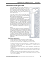
1
Application note - DURApulse Drives
AN-GS-014
Small mine hoist type loads
In this application note we will size and configure a
DURApulse variable frequency drive for a small mine
hoist. A mine hoist lifts mineral ore from one level to one
up in underground mines. The transport capacities are
variable, with motors ranging from hundreds of HP to
some in the thousands.
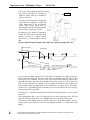
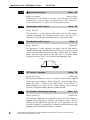
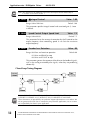
Reducer
Motor
Cage
In this case we have a vertical shaft small hoist with 2
cages or skips, in such a way that, when one loaded skip
goes up the other, empty, goes down.
The loading and unloading happens simultaneously by
mechanical means. See adjacent diagram.
The requirements are to have a daily lifting output of 1200
short tons in 15.5 hours for a distance of 350 feet. With the
mechanical design, is has been determined that the
unloaded cage weight is 2250 lb and the cable is 462 lb
total. That results in a cycle of 86 liftings per hour and since
the load/unload time is 10 second, the total travel time is
41.8 s. Acceleration and deceleration are equal to 3.5
second.
The calculations done by the mechanical engineering has
issued a curve of torques versus time referred to the motor
shaft operation from the point of view of the drive. Safety
factors are already included. The control is done with a
PLC, not shown in this example. The task in this example
is to design the drive components and configure the
parameters. We will make a list of the requirements of the
application in order to decide which parameters need
modifications.
Application requirements
•See the concept of control in the diagram on the next page.
•The drive will control a 460 Volt motor, horsepower to be determined.
•The maximum speed of the motor is 1800 RPM, connected to a reducer.
•The motor must accelerate to the maximum speed in 3.5 seconds, preferably with an Scurve profile. The motor must stop with a deceleration of 3.5 seconds, when the
mechanical brake will be applied.
•The operation of the system (start, stop, etc.) will be controlled by a controller, which
could be a PLC.
•The frequency of the VFD will be preset by an external contact. The command to raise
the hoist skip will be from one contact and the command to lower it will be from another
contact.
•The analog signal output of the VFD will indicate the motor current when it is working.
•The mine hoist is stopped with drum brakes, not controlled by the VFD, but by a master
relay, a safety control device.
THIS INFORMATION PROVIDED BY AUTOMATIONDIRECT.COM TECHNICAL SUPPORT IS SUPPLIED “AS IS”,
WITHOUT ANY GUARANTEE OF ANY KIND.
1
Application note - DURApulse Drives
AN-GS-014
•The system will incorporate dynamic braking.
•The system will utilize DC injection to
hold the motor when the mechanical
brake is released.
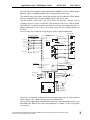
Drum Brake
•The drive will change to the creep speed
right before the stop point, to allow for
exact application of the mechanical
brake. That creep speed will be
determined by the PLC based on position
limit switches or proximity sensors.
Incoming
power
The adjacent figure shows the concept of
control. The shaft will have position limit
switches and there is a central control
room where is is commanded to start and
stop.
Next we show the required torque at the input of the gearbox, through the cycle:
Motor Frequency
Deceleration
Acceleration
60.5 Hz
3.5s
3.5 s
25 s
3.5s
25 s
3.5s
Time
10 s
Load
433 ft-lb
Torque
284 ft-lb
Skip 1 going up
144 ft-lb
Loading/
unloading
-52.7 ft-lb
-433 ft-lb
Skip 1 going down
Loading/
unloading
-284 ft-lb
As the maximum torque required is 433 ft-lb and the DURApulse can supply up to 150%
of the motor rated torque, we will use a motor with a rated torque of at least 289 ft-lb. The
closest we have is a 100 HP, 1785 rpm, 295 ft- lb. We sell several different inverter duty
type 100 HP motors. We select the Marathon inverter duty motor Y575-A774, Blue Max
with 115A of rated current at 460 Volt, with an encoder of 1024 pulses per revolution, to
assure stable speed, non dependent on the possibilities to change slip if the load is
variable. This is a possibility because the density or even the load may not be exactly the
same quantity during one load.
The motor has 3 normally closed contacts to determine overtemperature, that are wired
to the PLC.
The corresponding drive is the GS3-4100, with up to 150A rated current. We will also
select the braking resistor of the GS3-4100-BR type and a GS-4DBU braking unit.
The braking resistor allows the drive to brake up to 125% of the motor torque, which is
enough since we need only 52.7 ft-lb. This corresponds to about 19 % of the motor rated
torque.
2
THIS INFORMATION PROVIDED BY AUTOMATIONDIRECT.COM TECHNICAL SUPPORT IS SUPPLIED “AS IS”,
WITHOUT ANY GUARANTEE OF ANY KIND.
Application note - DURApulse Drives
AN-GS-014
AN-GS-014
We will select the sensorless vector method with feedback, to have a better torque
behavior, which is needed to perform the cycle consistently every time.
The motor heating calculation should be verified with the method of RMS power
during a complete cycle, or other method, shown later in this note.
The line reactor to be used is the GS-4100-LR, for 460 Volt, and the fuse kit
including the fuses is the GS-4100-FKIT. Please note that the fuse is sized for 600A,
600 Volt and is fast blow, to protect the drive and not the wire feeding the drive; In
general the branch circuit fusing is of a lower rating than that sized to protect the
AC drive.
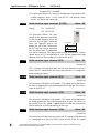
Next we show the Durapulse wiring diagram for this specific application.
PLC input module
DURAPULSE
Multi-function Digital Inputs:
PLC controlling elevator:
Output Contact:
+24V Power Source
(20mA max.)
Going up/Stop
DI1
Going down/Stop
DI2
External Reset
DI3
Multi-Speed 1
DI4
Multi-Speed 2
DI5
JOG
DI6
R1
R1C
Input Mode Setting
R1O
Sink
To - of 24 V power supply
SW1
Source
Digital Outputs:
DO1
AC Drive Fault
DO2
At Speed
DI7
External Fault (N.C.)
AC Drive Running
DI8
DO3
DI9
Encoder loss
DI10
DI11
DCM
Digital Signal Com.
DOC Digital Output Com.
Digital Output Com.
-
+
Power supply 24 VDC
Analog Inputs:
+10V Power Source
(20mA max.)
AO
AI1
(0 to 10V)
Multi-function Analog Output:
Scale 0-10VDC
Indicates Output
+
Current of VFD
–
ACM
0-10VDC @2mA
L1 L2 L3
+
+2
-
T1 T2 T3
Motor
Incoming supply
Braking unit
480V+-10%
(60Hz+-5%)
Overtemperature
Resistor
GS3-FB
OC 12V
Motor outlet
A
A
B
B
VP
DCM
OC=Open collector
TP=totem pole
TP 5V
A
B
PG
+12V
GND
Encoder output 12VDC
Note that it is necessary to determine the motor parameters for use with sensorless
vector control. This is done with the auto-tuning procedure.
The auto-tuning procedure should be done during the start up procedure. This is not
described here. Refer to the auto-tune procedure in Chapter 3 of the DURApulse
user manual.
THIS INFORMATION PROVIDED BY AUTOMATIONDIRECT.COM TECHNICAL SUPPORT IS SUPPLIED “AS IS”,
WITHOUT ANY GUARANTEE OF ANY KIND.
3
Application note - DURApulse Drives
AN-GS-014
Motor heating calculation:
There are several methods to check that the motor does not get too hot. Here is one
method:
The motor has a rated efficiency at full load of 94.5% respecting class F
insulation.This means that the losses at rated current (115A) are 4.34 kW. These
continuous operation losses will maintain the temperature below the limit of class
F (155 C in the hottest point). Since there is no continuous current, we will have to
estimate the heating effect during a cycle:
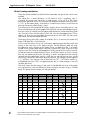
The motor losses are comprised of friction, cooling losses caused by the fan, iron
losses and the losses I2R on the copper. The I2R losses can be estimated because we
have the values R1 and R2 from the tables published on the AutomationDirect Web
site. R1=0.034 Ohm and R2=0.0219 Ohm; the value for the copper losses I2R are
about 3345 Watt; the rest should be the constant losses (995 Watt). The iron losses
and friction can be considered constant.
The energy during the cycle is about 42 seconds. That is, if constant the motor will
loose 4340 Watt x42 s=182280 Joule.
In the case of this hoist, we can say with certain approximation that the current will
change in the same way as the torque changes. On the following table we study
the torque on every segment of the torque curve, we determine the % of torque
related to the motor rated torque and then estimate the same increase on the
current; since The I2R losses are proportional to the square of the current, we have
to find the factor to multiply the basic losses at full load, shown on line A. Having
that, we can determine the watts; the energy in Joules corresponds to the watts by
seconds that the motor keeps running; since they are not constant on time, we do
the average value of the end values on each segment, for example, for the segment
3.5 + and 28.5-, the average value of the losses are (797 + 107 Watt)/2 and this is
multiplied by the time. This is an approximation, but it is close enough as we will
see from the result.
The result shows that the energy in the cycle is considerably less than if the motor
runs continuously. If the calculation has errors, the error can be as high as 107000
Joule. This proves that the motor will not get too hot.
Item Time
4
Torque Torque
Current
Squared Factor
Losses
Losses
in Watt
in Joules {sum}
n/a
second lb-ft
per cent A
A*A
A
Rated
295
100%
115
13225
1in p/u
3345
B
0+
433
146.8
168.8
28492
2.154
7205
C
3.5-
432
146.4
168.4
28361
2.144
7172
D
3.5+
283.9
96.2
110.7
12247
0.926
3097
E
28.5-
144
48.8
56.1
3153
0.238
796
F
28.5+
52.7
17.9
38 (No load) 1444
0.109
365
G
32-
52.0
17.6
38 (No load) 1444
0.109
365
1278
H
32+
0
0
0
0
0
I
42
0
0
0
0
0
Joules
25160
48662
75100
THIS INFORMATION PROVIDED BY AUTOMATIONDIRECT.COM TECHNICAL SUPPORT IS SUPPLIED “AS IS”,
WITHOUT ANY GUARANTEE OF ANY KIND.
Application note - DURApulse Drives
AN-GS-014
Parameter configuration
In order to fulfill the requirements of this application, the parameters must be set as
follows:
P 0.00
Motor Nameplate Voltage
Value: 460
Range: 200V class: 200/208/220/230/240
460V class: 380/400/415/440/460/480
Default 240
Default 480
The value of this parameter is defined on the nameplate of the motor.
P 0.01
Motor Nameplate Amps
Range: AC drive rated currentx(0.1 to 1.0)
Value: 115
Default IVFD (A)
The value of this parameter is defined on the nameplate of the motor.
P 0.02
Motor Base Frequency
Value: 60
Range: 50/60/400
Default 60
The value of this parameter is found on the nameplate of the motor.
.P
0.03
Motor Base RPM
Value: 1785
Range: 375 to 24,000 RPM
Default 1750
The value of this parameter is defined on the nameplate of the motor.
P 0.04
Motor maximum RPM
Value: 1800
Range: P 0.03 to 24,000 RPM
Default P 0.03
The value of this parameter is determined by the requirements of the
application.
P 1.00
Stop Methods
Value: 00
Default 00
Range: : 00 Ramp to stop
01 Coast to stop
This parameter causes the motor to stop in a fixed time.
P 1.01
Acceleration time 1
Range: 0.1 to 600 sec
Value: 5.0
Default 10 sec
The motor must accelerate from 0 RPM to the maximum speed of the
motor (P 0.04) in 5 seconds.
THIS INFORMATION PROVIDED BY AUTOMATIONDIRECT.COM TECHNICAL SUPPORT IS SUPPLIED “AS IS”,
WITHOUT ANY GUARANTEE OF ANY KIND.
5
Application note - DURApulse Drives
P 1.02
AN-GS-014
Deceleration time 1
Value: 5.0
Range: 0.1 to 600 s.
Default 30 sec
This parameter is used to define in 5 seconds as the deceleration time that the
frequency drive is going to impose. The speed change is linear unless the Scurve is activated. This is a typical value for low speed elevators.
P 1.03
Acceleration with S-curve
Value: 03
Range: 00 to 07
Default 00
This parameter is used whenever the motor and the load need a
smoother acceleration. The acceleration with S-curve is set in 03. This is
necessary to avoid abrupt accelerations of the skip and the cable.
P 1.04
Deceleration with S-curve
Value: 3
Range 00 to 07
Default 00
This parameter is used whenever the motor and the load need a
smoother deceleration. The deceleration with the S-curve is set in 03 and
will be activated when the contact to stop is deactivated. This contact
opens when the limit switch of the stop level is activated, before
reaching that level. The PLC will make the corresponding logic.
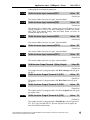
Frequency
Time
Characterístic
of S-curve
P 1.18
Characterístic
of S-curve
DC Current injection
Range: 00 to 100%
Value: 10
Default 00
This parameter determines the DC current of motor braking applied
during starting and stopping. When setting DC Current Braking, please
notice that 100% is equal to the rated current of the drive. It is
recommended to start with low DC Current Braking Level and then
increase until proper holding torque has been attained.
P 1.20
DC Injection time during starting
Range: 0.0 to 5.0 s.
Value: 0.5
Default 0.0
This parameter determines the period in which the DC injection is
applied to the motor during starting of the frequency drive. The DC
braking will be applied for the time set in this parameter until the
minimum frequency is reached. This is done to avoid the elevator cage
dropping when the mechanical brake is released.
6
THIS INFORMATION PROVIDED BY AUTOMATIONDIRECT.COM TECHNICAL SUPPORT IS SUPPLIED “AS IS”,
WITHOUT ANY GUARANTEE OF ANY KIND.
Application note - DURApulse Drives
P 1.21
AN-GS-014
DC Injection during stop
Value: 0.5
Range: 0.0 to 25.0 s.
Default 0.0
This parameter determines the duration for which the injection voltage will
be applied to the motor during stopping. If it is planned to stop with DC
braking, then P1.00 must be set as Ramp to stop (00).
P 1.22
Value: 1.5
Start point for DC injection
Range: 0.0 to 60.0 Hz
Default 0.0
This parameter determines the frequency where the DC injection
braking during the deceleration.We want to apply DC so that when the
mechanical brake get released there is already a resistive torque in the
motor.
Main
frequency
Start point for DC braking
1 Hz
P 1.22
time
P 1.21 = 0.5 s
P 1.20 =0.5 s
ON
OFF
Operation
command
DC Injection level
P 1.18
P 2.10
Control mode
Range: 00:
01:
02:
03:
V/Hz open loop control
V/Hz closed loop control
Sensorless vector
Sensorless vector with external feedback.
Value: 03
Default 00
This parameter determines the method of control of the drive. We
selected mode 03 to have better torque control compared to Volt/ Hertz
mode.
P 3.00
Source of operation command
Value: 02
Default 00
Settings 00
01
Operation determined by Digital Keypad
Operation determined by external control terminals.
Keypad STOP is enabled.
02 Operation determined by external control terminals.
Keypad STOP is disabled.
03 Operation determined by communication interface.
Keypad STOP is enabled.
04 Operation determined by communication interface.
THIS INFORMATION PROVIDED BY AUTOMATIONDIRECT.COM TECHNICAL SUPPORT IS SUPPLIED “AS IS”,
WITHOUT ANY GUARANTEE OF ANY KIND.
7
Application note - DURApulse Drives
AN-GS-014
Keypad STOP is disabled.
• This parameter defines the source of the operation command for the
variable frequency drive. In this case the PLC, and possibly some
sensors, will define the commands.
P 3.01
Multi-function input terminals (DI-DI2)
Settings
DI1 - FWD/STOP
Value: 00
Default 0.0
DI2 - REV/STOP
This parameter defines the input
source for the operation commands
of the variable frequency drive. We
want the skip to begin movement
Going Up/Stop
DI1
when the operator presses the
button that will close a contact on
Going Down/Stop DI2
the PLC and we want to stop when
DCM
near the other level. The operation
can also be automatic. The stop function will be reached with 2 preset
speeds; one at 60.5 Hz and the other at 3 Hz. The low speed is the creep
speed to allow the skip to stop just in front of the level.
P 3.02
Multi-function input terminal (DI3)
Value: 02
Default 00
This is a button in the machine room that will reset the drive in case of a
failure. The PLC should check that every safety element is in compliance
before resetting the drive
P 3.03
Multi-function input terminal (DI4)
Value: 03
Default 00
This parameter will define multi-speed 1. This speed will be defined as
the normal speed of the cage and corresponds to 1800 rpm. The value is
to be set with P5.01.
P 3.04
Multi-function input terminal (DI5)
Value: 04
Default 00
This parameter will define multi-speed 2. This speed will be defined as
the creep speed of the skip and corresponds to 89 rpm. The value is to
be set with P5.02. This speed is applied for the last few feet close to the
level to allow for an exact positioning of the cage.
P 3.04
Multi-function input terminal (DI6)
Value: 09
Default 00
This parameter will define the jog command. This speed will be defined
to correspond to 92 rpm. The value is to be set with P5.00. This speed
8
THIS INFORMATION PROVIDED BY AUTOMATIONDIRECT.COM TECHNICAL SUPPORT IS SUPPLIED “AS IS”,
WITHOUT ANY GUARANTEE OF ANY KIND.
Application note - DURApulse Drives
AN-GS-014
is designed for maintenance operations.
P 3.06
Multi-function Input terminal(DI7)
Value: 99
Default 00
This terminal does not have any input. Input disabled
P 3.07
Multi-function Input terminal(DI8)
Value: 01
Default 00
This terminal has a contact from a master relay that will open in case of
voltage shutdown as well as any other emergency situation. This master
relay shall also remove energy from the drum brake to cause an
immediate stop of the skip.
P 3.08
Multi-function Input terminal(DI9)
Value: 99
Default 00
This terminal does not have any input. Input disabled
P 3.09
Multi-function Input terminal(DI10)
Value: 99
Default 00
This terminal does not have any input. Input disabled
P 3.10
Multi-function Input terminal(DI11)
Value: 99
Default 00
This terminal does not have any input. Input disabled
P 3.11
Multi-function Output Terminal 1 (Relay Output)
Value:00
Default 00
This output terminal is programmed as AC drive running and will go to
the PLC.
P 3.12
Multi-function Output Terminal 2 (DO1)
Value: 01
Default 01
This output terminal is programmed as AC drive Fault and will go to
the PLC.
P 3.13
Multi-function Output Terminal 3 (DO2)
Value: 02
Default 02
This output terminal is programmed as AC drive At Speed and will go to
the master relay.
P 3.14
Multi-function Output Terminal 4 (DO3)
Value: 15
Default 03
This output terminal is programmed as Encoder loss and will go to the
PLC. This signal will tell the PLC that the skip will wait for repair on
one of the end travel positions.
THIS INFORMATION PROVIDED BY AUTOMATIONDIRECT.COM TECHNICAL SUPPORT IS SUPPLIED “AS IS”,
WITHOUT ANY GUARANTEE OF ANY KIND.
9
Application note - DURApulse Drives
P 4.00
AN-GS-014
Source of Frequency Command
Value: 02
Default: 01
Settings: 01Frequency determined by digital keypad up/down
02 Frequency determined by 0 to +10V input on AI1 terminal.
We will set the analog setpoint for frequency with mode 02.
P 4.11
Analog Output Signal
Value 01
Range: 00 - Frequency Hz
Default 00
01 - Current A
02 - PV
This parameter selects current to be the output on the 0 to 10V A0 output.
P5.00
Jog
Value: 3.1
Range: 0.0 to 400.0 Hz
Default 6.0
The Jog Command is selected by to Multi-Function Input Terminal (P 3.04 )
set to the Jog Function (09) that corresponds to 92 RPM.
P 5.01
Multi-Speed 1
Value: 60.5
Default 00
The multi-speed 1 value is defined as 60.5 Hz, that corresponds to 1800
rpm and will be used at the normal speed of the skip.
P 5.02
Multi-Speed 2
Value: 3.0
Default 00
The multi-speed 2 value is defined as 3.0 Hz, that corresponds to 89 rpm
and will be used at the creep speed of the skip.
P 6.00
Thermal Overload type selection
Value: 00
Modes: 00 - Use with inverter duty motor
01 - Use with standard fan cooled motor
02 - Inactive
Default 00
The mode 00 uses the normal inverse time thermal overload protection over the
full speed range, tripping at 100% of motor current with tripping @ 150% in
one minute. The mode 01 is used to derate the thermal protection at lower
speeds in such a way that there is a linear derating from rated speed to speed
zero. The current to trip at 0 Hz is 40%. We use constant torque in this case.
P 6.03
Reverse Operation Inhibit
Value: 00
Default Setting: 00
10
THIS INFORMATION PROVIDED BY AUTOMATIONDIRECT.COM TECHNICAL SUPPORT IS SUPPLIED “AS IS”,
WITHOUT ANY GUARANTEE OF ANY KIND.
Application note - DURApulse Drives
Settings: 00
Enable Reverse Operation
01
Disable Reverse Operation
AN-GS-014
This parameter determines whether the AC Motor Drive can operate in the
reverse direction. In this case we clearly will enable reverse operation.
P 8.00
User Defined Display Function
Value: 00
Default 00
Settings:
00
01
02
03
04
05
06
07
08
09
Output Frequency (Hz)
Motor Speed (RPM)
Scaled Frequency
Output Current (A)
Motor Load (%)
Output Voltage(V)
DC Bus Voltage (V)
PID Reference
PID Feedback (PV)
Frequency Reference
This value is the Default to indicate the Output Frequency
P 10.00
Encoder Pulse Per Revolution
Value: 1024
Range: 01 to 20000
Default 1024
An encoder is used as a transducer to feed back the motor speed, and
this parameter defines the number of pulses for each cycle of the PI
control.
P 10.01
Encoder Type Input
Value: 02
Range: 00: Disable
Default 00
01: Single Phase
02: Quadrature, FWD - CCW
03: Quadrature, FWD - CW
This parameter is used to specify encoder signal type. Settings 02 and 03
are used to distinguish motor rotation in relation to the quadrature type
encoder signal. Error message “ENC SIGNAL ERROR” will come up if
motor rotation does not match quadrature settings.
P 10.02
Proportional Control
Value: 1.00
Range: 0.0 to 10.0
Default 1.00
This parameter specifies Proportional control and associated gain (I),
used for vector control with encoder feedback. Leave as default.
THIS INFORMATION PROVIDED BY AUTOMATIONDIRECT.COM TECHNICAL SUPPORT IS SUPPLIED “AS IS”,
WITHOUT ANY GUARANTEE OF ANY KIND.
11
Application note - DURApulse Drives
AN-GS-014
Note: The diagram on the following page shows the output control relationship of
P 10.02, P 10.03 and P 10.04.
P 10.03
Integral Control
Range: 0.0 to 100.0 sec
Value: 1.00
Default 1.00
This parameter specifies integral control and associated gain (I). Leave
as default.
P 10.04
Speed Control Output Speed Limit
Range: 0.0 to 20.0%
Value: 7.5
Default 7.5
This parameter limits the amount of correction by the PI control on the
output frequency when controlling speed. It can limit the maximum
output frequency.
P 10.05
Encoder Loss Detection
Range: 00: Warn and continue operation
Value: 00
Default 00
01: Warn and RAMP to stop
02: Warn and COAST to stop
This parameter governs the response of the drive to the feedback signals,
such as the analog or encoder pulse signals, when they are performing
abnormally.
Closed Loop Tuning Diagram
THIS INFORMATION PROVIDED BY AUTOMATIONDIRECT.COM TECHNICAL
SUPPORT IS SUPPLIED “AS IS”, WITHOUT ANY GUARANTEE OF ANY KIND.
These documents are provided by our technical support department to assist others. We
do not guarantee that the data is suitable for your particular application, nor we assume
any responsibility for them in your application.
12
THIS INFORMATION PROVIDED BY AUTOMATIONDIRECT.COM TECHNICAL SUPPORT IS SUPPLIED “AS IS”,
WITHOUT ANY GUARANTEE OF ANY KIND.