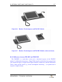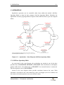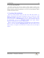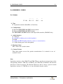
1
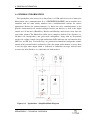
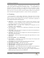
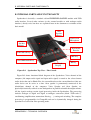
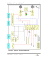
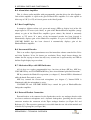
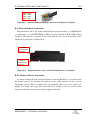
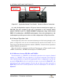
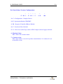
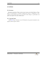
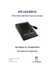
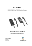
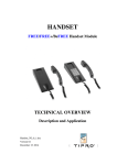
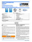
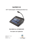
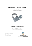
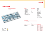
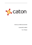
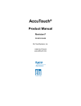
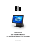
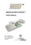
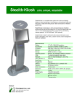
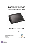
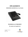
SPEAKERBOX FREE/FREE+/BeFREE InterCom Module TECHNICAL OVERVIEW Description and Application SpeakerBox_TO_05.doc Version 05 May 23, 2012 TABLE OF CONTENTS II TABLE OF CONTENTS A. GENERAL INFORMATION.......................................................................................A-1 A.1. Terminology ..........................................................................................................A-2 A.2. Highlights ..............................................................................................................A-3 A.3. Technical Characteristics ......................................................................................A-4 B. INTEGRAL PARTS AND FUNCTIONALITY .......................................................... B-1 B.1. Microphone Amplifier........................................................................................... B-3 B.2. Handset/Headset Amplifier ................................................................................... B-3 B.3. Hands-Free Amplifier............................................................................................ B-3 B.4. Alarm/Alert Amplifier........................................................................................... B-4 B.5. Bar-Graph Display................................................................................................. B-4 B.6. Incremental Encoder.............................................................................................. B-4 B.7. Mechanical Keys with LED Indicators ................................................................. B-4 B.8. External Headset Connection ................................................................................ B-4 B.9. External Handset Connection ................................................................................ B-5 B.10. Audio and Power Connection.............................................................................. B-5 B.11. External Tipro Bus Cable .................................................................................... B-6 B.12. Differences between TM-FSx and TM-FEx........................................................ B-6 B.13. Differences between TM-FSU and TM-FMU..................................................... B-7 C. OPERATION ................................................................................................................ C-1 C.1. Off-Line Operating Mode...................................................................................... C-1 C.2. On-Line Operating Mode ...................................................................................... C-2 C.3. Using Tipro USB Audio Modules......................................................................... C-2 D. ORDERING CODES....................................................................................................D-1 D.1. Module ..................................................................................................................D-1 D.2. Cables ....................................................................................................................D-2 D.3. Power Supply ........................................................................................................D-2 D.4. Stand-Alone Version (Configuration)...................................................................D-3 E. REFERENCES.............................................................................................................. E-1 F. NOTICES .......................................................................................................................F-1 F.1. Disclaimer ...............................................................................................................F-1 F.2. Copyright Notice.....................................................................................................F-1 SPEAKERBOX – TECHNICAL OVERVIEW A. GENERAL INFORMATION A-1 A. GENERAL INFORMATION The Speakerbox (also referred to as InterCom) is a USB audio device for a hands-free bidirectional voice communication. It is a FREE/FREE+/BeFREE add-on module to be combined with the other family members into a multifunctional console for various applications. Besides the primary function (i.e. hands free voice communication) it also provides connection for an external analogue headset and handset, as well as the digital control over all the three (HandsFree, Headset and Handset) audio devices that share the same audio channel. The Hands-Free audio device comprises built-in Voice Speaker (i.e. left-hand side loudspeakers) and goose-neck microphone, along with an incremental encoder for volume control, bar-graph multicolour LED indicator and two function keys (MIC key and HF key). Two more keys are provided for immediate loudspeaker volume control of the external headset and handset. Since the output audio channel is stereo, there is also the right audio output which is dedicated to alarm/alert messages from the host system at the Alert Speaker (i.e. right-hand side loudspeakers). Figure A.1 Speakerbox – Simplified Block Diagram SPEAKERBOX – TECHNICAL OVERVIEW A. GENERAL INFORMATION A-2 All embedded functions (switching between the devices, volume control, side-tone feature, noise gating and compression of microphone signals …) are programmable via ChangeMe software and controllable by the application software. By default the module operates as per predefined state diagram (see chapter C) in so-called “Off-Line” operating mode, but can be at any time switched (respective Windows API has been provided for) under total control of the application software i.e. into the “On-Line” operating mode. A.1. Terminology As the Speakerbox is a quite complex audio device, certain terms need to be clearly defined in order to avoid misunderstanding. The following definitions do not necessarily represent generally accepted technical facts, but merely a nomenclature explanation in order to help understand the document properly. ♦ audio device – a device comprising a transducer to turn an electric signal into a sound (loudspeaker), as well as a transducer to turn a sound pressure into an electric signal (microphone), both along with the associated electronic circuitry ♦ mono audio device – an audio device comprising one loudspeaker and one microphone – same as audio device ♦ stereo audio device – an audio device comprising two loudspeakers (left and right) and one microphone ♦ audio output – output audio signal of a computer to be connected to the Speakerbox (it is input signal to the Speakerbox) ♦ audio input – input audio signal of a computer to be connected to the Speakerbox (it is output signal of the Speakerbox) ♦ audio channel – a pair of one input and one output audio signal addressed to a mono audio device ♦ mono audio channel – same as audio channel ♦ stereo channel – a combination of one input and two output (left and right) audio signals addressed to a stereo audio device ♦ voice channel – the pair of input audio signal and left output audio signal ♦ alarm output (alert output) – right output audio signal ♦ USB audio output – USB (digital) output audio signal of a computer ♦ USB audio input – USB (digital) input audio signal of a computer ♦ USB audio port – regular USB downstream port of a computer used to transmit two USB output signals (left and right) and to receive one USB input audio signal ♦ analogue audio output – analogue output audio signal of a computer with 0 dBu (or 0 dBm) signal range, usually referred to as LINE OUT SPEAKERBOX – TECHNICAL OVERVIEW A. GENERAL INFORMATION A-3 ♦ analogue audio input – analogue input audio signal of a computer with 0 dBu (or 0 dBm) signal range, usually referred to as LINE IN ♦ microphone audio input – analogue input audio signal of a computer intended for a direct microphone (without an amplifier) connection, usually referred to as MIC IN A.2. Highlights APPLICATIONS ♦ dispatcher terminals ♦ banking & trading consoles ♦ multifunctional control panels ♦ digital telephony (e.g. Voice over IP) devices CONCEPT AND MODULARITY ♦ ergonomic hands-free voice communication device ♦ combination of a USB audio device and an HID keyboard ♦ plug & play operation with generic USB audio and USB HID keyboard drivers ♦ configurable switching between the hands-free and external analogue audio devices ♦ separate output for alarm/alert tones/messages ♦ integrated acoustic shock protection (TM-FxU only) ♦ external analogue audio devices (handset and headset) effectively converted into the corresponding digital (USB) devices ♦ combinable with other FREE/FREE+/BeFREE add-on modules (e.g. handsets, touchcomputers, touchmonitors, Chameleon, keypads, ID modules, …) into multifunctional terminals ♦ stand-alone operation as an external Tipro bus module (connected by respective cable to another Tipro module with integrated Tipro controller) ♦ stand-alone operation as a FREE/FREE+/BeFREE module with integrated Tipro USB controller (TM-FMU only) ♦ optional analogue audio interface (TM-FxA) PROGRAMMABILITY ♦ all implemented audio functions are programmable ♦ six programmable mechanical keys VERSATILITY ♦ user configurable predefined operating mode (“Off-Line”) ♦ dynamically controlled operation by the application software (“On-Line”) ♦ keys with dedicated hardware function and/or programmable keys SPEAKERBOX – TECHNICAL OVERVIEW A. GENERAL INFORMATION A-4 ♦ LED indicators with dedicated hardware function and/or programmable indicators A.3. Technical Characteristics ELECTRICAL ♦ power supply (analogue circuitry): 12V ± 5% (via Tipro Power Bus from Powered FREE+ Touchmonitor or BeFREE Touchcomputer or alternatively from an external power supply, e.g. TM-VPB) ♦ power supply (digital circuitry): 5V ± 5% (from Tipro controller via Tipro bus) ♦ current consumption (analogue circuitry): up to 600 mA (300 mATYP), depending on the actual volume settings ♦ current consumption (digital circuitry): up to 100 mA (50 mATYP) ♦ additional current consumption of TM-FMU: 25 mATYP (45 mAMAX) ♦ control interface: TIPRO bus (Speakerbox as standard FREE/FREE+/BeFREE module – TM-FSx) ♦ control interface: External TIPRO FREE/FREE+/BeFREE module – TM-FEx) bus (Speakerbox as add-on external ♦ control interface: USB (Speakerbox as FREE/FREE+/BeFREE module with integrated Tipro USB controller – TM-FMU) ♦ audio interface: USB (USB Speakerbox – TM-FxU) ♦ audio interface: Analogue audio: LINE IN + LINE OUT (Analogue Speakerbox – TM-FxA) ♦ power connectors: Tipro Power bus connector: 10-pin Micro-MaTch receptacle (female) on the PCB - to power Speakerbox from Powered FREE+ Touchmonitor or BeFREE Touchcomputer Audio & Power connector: RJ 8P/8C accessible from the bottom part of the housing - to power Speakerbox from an external 12V Power Supply ♦ interface connectors: left-hand side Tipro bus connector: 6-pin Micro-MaTch header (male) at the end of a 100 mm long ribbon cable right-hand side Tipro bus connector: 6-pin Micro-MaTch receptacle (female) on the PCB Audio & Power connector: RJ 8P/8C accessible from the bottom part of the housing (USB and analogue variants have the same connector type, but to be used with different cables, i.e. TM-CZV and TM-CZB, respectively) SPEAKERBOX – TECHNICAL OVERVIEW A. GENERAL INFORMATION A-5 MECHANICAL ♦ casing: plastic ABS, black colour – C15 ♦ net dimensions: 138 x 222 x 51 (without goose-neck microphone) (W/D/H) [mm] ♦ gross dimensions (with side-covers): 158 x 222 x 51 (W/D/H) [mm] ♦ goose-neck microphone length/height: 350±50mm ♦ weight: 700 g (approximately) ♦ protection (sealing) grade: IP 30 (according to EN 60529) ENVIRONMENTAL ♦ operating ambient temperature range: 0°C to +40°C ♦ storage ambient temperature range: -10° C to +50°C ♦ relative humidity range: 20% to 80% (non-condensing) AUDIO ♦ Loudspeakers two in parallel within the left output two in parallel within the right output type: dynamic rated power: 2 W output sound pressure level (SPL): 85 dB ± 3 dB @ 1 W @ 1 kHz @ 0.5 m distance ♦ Goose-neck Microphone type: electret condenser, unidirectional max input: 120 dB SPL ♦ Analogue amplifiers designed to meet narrow-band telephony standards frequency pass-band: (200 Hz - 5 kHz) TYP output power: 4 x 1 W (2 x 2 x 1 W) ♦ USB Audio Codec model: Texas Instruments PCM 2902x MECHANICAL KEYS ♦ keyswitch model: Cherry MX key travel: 3.6mm to 4.0mm total, (2 ± 0.6) mm pretravel actuating force: (60 ± 20) cN reliability (Mean Cycles To Failure): MCTF = 1 billion (109) press/release cycles (50 million is guaranteed minimum) ♦ keycaps construction: separate body and cover SPEAKERBOX – TECHNICAL OVERVIEW A. GENERAL INFORMATION A-6 size: single keycap bodies (with cut-out for LED): CN15 black colour keycap covers: transparent key legends: pictograms printed on a transparent paper, underneath keycap covers SPEAKERBOX – TECHNICAL OVERVIEW B. INTEGRAL PARTS AND FUNCTIONALITY B-1 B. INTEGRAL PARTS AND FUNCTIONALITY Speakerbox is basically a standard add-on FREE/FREE+/BeFREE module with USB audio interface. Several other variants (as the external module or with analogue audio interface) already exist, but these are explained latter in the document as variations of the basic model. Alert Speaker Display Goose-neck Microphone Voice Speaker Display Incremental Encoder VOLUME UP key MIC key VOLUME DOWN key Bar-Graph Display Figure B.1 HF key Speakerbox Top View – The Console Figure B.2 shows functional block diagram of the Speakerbox. Voice channel of the computer (left output audio signal and input audio signal) is routed to the selected mono audio device that can be Hands-Free, the external headset or the external handset. Only one audio device can be active at a time. Alert speaker is permanently connected to the Alert/Alarm channel of the computer. Voice Speaker and Alert Speaker are physically/electrically realized as two loudspeakers in parallel to double the output volume. All the signals undergo certain signal processing inside the Speakerbox. The processing includes analogue to digital and digital to analogue conversion (block “USB codec”), conditioning (amplification, attenuation, filtering …), sensing and switching. The complete processing is programmable via ChangeMe and can be dynamically changed during the operation in so-called On-Line operating mode. SPEAKERBOX – TECHNICAL OVERVIEW B. INTEGRAL PARTS AND FUNCTIONALITY Figure B.2. Speakerbox – Functional Block Diagram SPEAKERBOX – TECHNICAL OVERVIEW B-2 B. INTEGRAL PARTS AND FUNCTIONALITY B-3 B.1. Microphone Amplifier This is a logarithmic audio amplifier with programmable gain, noise gating threshold and compression ratio. It processes microphone signal of the currently selected audio device: Hands-Free (goose-neck microphone), Headset or Handset. Noise gating feature enables ambient noise to be suppressed. All sounds below the threshold are removed inside the amplifier, so with higher threshold the microphone needs to be used closer to the mouth and speech needs to be louder to get through the amplifier. The compression feature enables compression of the output signal dynamics in order to minimize the difference between quiet and loud speech. The amplifier is also capable of limiting extremely loud speech thus preventing distortion and popping. The overall gain can be even lower than one (i.e. attenuation) as well as equal to zero (i.e. totally muted input). Recent (since 2Q2009) USB Speakerbox modules (i.e. TM-FxU) comprise an additional microphone preamplifier within the HandsFree device to provide for adjustment of the goose-neck microphone range. B.2. Handset/Headset Amplifier This is a linear audio amplifier with programmable gain that drives loudspeaker of currently active external audio device: Headset or Handset. It is also a summing amplifier that can add a part of the microphone signal to the output signal for the loudspeaker (socalled “side-tone” feature). The “side-tone” feature is essential to a user of the Handset/Headset as it provides an immediate (without a delay) audio feedback. Side-tone level is also programmable. Gain of this amplifier (i.e. volume of the loudspeaker inside handset and headset) can be adjusted by user in normal operation via two mechanical keys (VOLUME UP and VOLUME DOWN) at the lower left-hand side of the module. The selected level is immediately displayed at the bar-graph display in orange colour (10 volume levels + mute). B.3. Hands-Free Amplifier This is a linear audio amplifier with programmable gain that drives the Voice Speaker. Gain of this amplifier (i.e. volume of the Voice Speaker) can be adjusted by the user in normal operation via incremental encoder (i.e. endless digital potentiometer) at the lower right-hand side of the module. The selected level is immediately displayed at the bar-graph display in green colour (20 volume levels + mute). The amplifier can deliver up to 2 W (2 x 1 W) of electric power to the Voice Speaker. SPEAKERBOX – TECHNICAL OVERVIEW B. INTEGRAL PARTS AND FUNCTIONALITY B-4 B.4. Alarm/Alert Amplifier This is a linear audio amplifier with programmable gain that drives the Alert Speaker. Gain of this amplifier is equal to the gain of Hands-Free amplifier. It is also capable to deliver up to 2 W (2 x 1 W) of electric power to the Alert Speaker. B.5. Bar-Graph Display It comprises 10 three-colour (red, green and orange) LEDs to display level of the left output signal as VU meter (red colour), or gain of the Handset/Headset amplifier (orange colour) or gain of the Hands-Free amplifier (green colour). By default it constantly operates as VU meter. If a move of the incremental encoder has been detected it automatically displays gain of the Hands-Free amplifier. If a press of VOLUME UP or VOLUME DOWN key has been detected it automatically displays gain of the Handset/Headset amplifier. B.6. Incremental Encoder This is an endless digital potentiometer used for immediate volume control of the Voice and Alert Speakers. It has 24 detents per revolution. Every single detent changes the volume for one step up or down, but only every second one is represented by one LED in the Bar-Graph display in green colour. B.7. Mechanical Keys with LED Indicators All six keys are regular programmable keys, but four of them (HF key, MIC key, VOLUME UP key and VOLUME DOWN key) have also additional predefined functions. HF key controls the Hands-Free operation (see chapter C). Internal LED is illuminated while the hands-Free mode is active. MIC key controls the Goose-neck microphone (see chapter C). Internal LED is illuminated while the microphone is active. VOLUME UP and VOLUME DOWN keys control the gain of Handset/Headset loudspeaker amplifier. B.8. External Headset Connection External headset to be connected to the Speakerbox can be any analogue headset with an electret condenser microphone and a dynamic loudspeaker, providing that the audio connector matches the connector of the Tipro analogue handset (see Figure B.3 and Reference [1]). The respective connector is accessible from the rear side of the module and is labelled by a pictogram (see Figure B.4). SPEAKERBOX – TECHNICAL OVERVIEW B. INTEGRAL PARTS AND FUNCTIONALITY B-5 PIN 1: MIC+ PIN 2: SPK+ PIN 3: SPKPIN 4: MIC- Figure B.3 External Handset/Headset Connector and Respective Signals B.9. External Handset Connection External handset can be any of the standard Tipro analogue handsets (e.g. TM-HHA-6A – see Reference [1]) with PTT/PTM key (PTT is acronym of Push To Talk, PTM of Push To Mute). The respective connector is accessible from the rear side of the module and is labelled by a pictogram (see Figure B.4). Handset Connection Display Headset Connection Display Figure B.4 Speakerbox Rear View – External Audio Device Connections B.10. Audio and Power Connection As shown in Figure B.5 the Audio and Power connector (RJ 8P/8C) is accessible from the bottom part of the housing. Depending on the audio interface of the selected Speakerbox model (USB or Analogue) the corresponding cable needs to be chosen (see chapter D.2). Both cable types have split end at the computer side, one end for audio signals and the other to provide for a power supply connection. SPEAKERBOX – TECHNICAL OVERVIEW B. INTEGRAL PARTS AND FUNCTIONALITY External Tipro Bus cable Connection Figure B.5 B-6 Audio & Power cable Connection Speakerbox Bottom View (Detail) – Interface & Power Connections As a rule, the Speakerbox requires 12V power from an external power supply, e.g. TM-VPB. The only exception to the rule is Speakerbox as the standard add-on module (TM-FSx) used in a FREE+/ BeFREE configuration along with Powered FREE+ 15 touchmonitor or BeFREE touchcomputer, where the touchmonitor or the touchcomputer provides power to the rest of the configuration via Tipro Power Bus. B.11. External Tipro Bus Cable External Tipro bus cable comes out from the bottom part of the housing through a cable gland (see Figure B.5) and can not be detached from the outside of the module. It is an integral part of the External Speakerbox modules (TM-FEx). Standard add-on Speakerbox modules (TM-FSx) do not have it. This cable should be connected to the External Tipro bus port of Tipro controller inside a FREE+ touchmonitor, a BeFREE touchcomputer or a FREE keyboard. B.12. Differences between TM-FSx and TM-FEx External modules (e.g. TM-FEU) are functionally equivalent to the respective Standard modules (e.g. TM-FSU). The only difference is in physical connection of the Tipro bus cable. External modules are intended for applications where a configuration (e.g. the one presented in Figure B.6) needs to be split into two parts (as presented in Figure B.7), but maintaining all other original properties. For the sake of clarity, the cables (presented in Figure B.5) between the external Speakerbox and the Touchcomputer are not shown in Figure B.7. SPEAKERBOX – TECHNICAL OVERVIEW B. INTEGRAL PARTS AND FUNCTIONALITY B-7 Figure B.6 Handset, Touchcomputer and TM-FSU Module Figure B.7 Handset, Touchcomputer and TM-FEU Module (cables not shown) B.13. Differences between TM-FSU and TM-FMU The TM-FMU is a stand-alone version and a functional superset of the TM-FSU module. It additionally incorporates a Tipro USB controller with built-in bus-powered hub (one downstream port is occupied by the Tipro controller, another one with the USB Audio Codec). Other specific details (e.g. current consumption, interfacing …) are pointed out in respective chapters hereby. SPEAKERBOX – TECHNICAL OVERVIEW C. OPERATION C-1 C. OPERATION Speakerbox operation can be controlled either from within the module (Off-Line Operating Mode) or from the host computer (On-Line Operating Mode). Normally, the Speakerbox is factory preprogrammed to operate in the Off-Line mode as per state diagram below. MIC key pressed / Connect Gooseneck Mic, Send „MIC key pressed“ key event Headset unit connected, HF key released / Disconnect Handset, Disconnect Gooseneck Mic, Disconnect LS, Connect Headset, Send „Headset Connected“ key event MIC key released / Disconnect Gooseneck Mic, Send „MIC key released“ key event HANDSFREE Handset On-Hook, HF key pressed / Connect LS, Disconnect Handset, Send „On-Hook“ key event Headset unit disconnected, Handset On-Hook, HF key pressed / Connect LS, Disconnect Headset, Send „Headset Disconnected“ key event Handset Off-Hook, HF key released / Disconnect LS, Disconnect Gooseneck Mic, Connect Handset Send „Off-Hook“ key event HEADSET Headset unit disconnected, Handset Off-Hook / Connect Handset, Disconnect Headset, Send „Headset Disconnected“ key event HANDSET PTT key pressed / Send „PTT pressed“ key event PTT key released / Send „PTT released“ key event Note: Key events („MIC key pressed“, „MIC key released“, „On-Hook“, „Off-Hook“, „PTT pressed“, „PTT released“, „Headset connected“, „Headset disconnected“, „HF key pressed“, „HF key released“) are sent via USB regardless of the current state. Headset unit connected / Disconnect Handset, Disconnect Gooseneck Mic, Disconnect LS, Connect Headset, Send „Headset Connected“ key event Figure C.1. Speakerbox – State Diagram (Off-Line Operating Mode) C.1. Off-Line Operating Mode As represented in the state diagram, the speakerbox can remain in one of the three possible states: HANDSFREE, HEADSET or HANDSET. Since the Headset is the highest priority audio device, the default state is HEADSET if an external headset is connected. The lowest priority state is HANDSFREE. Arrows in the state diagram define possible transitions between the states. Each transition is described by the event which may cause it to happen (text in red colour) and the actions to be taken upon the event (text in black colour). SPEAKERBOX – TECHNICAL OVERVIEW C. OPERATION C-2 C.2. On-Line Operating Mode In On-Line operating mode the host computer controls complete operation of the module. This mode is intended for advanced users having full control over the application software. Respective technical documentation as well as the associated Windows API are available upon qualified request. C.3. Using Tipro USB Audio Modules Besides the USB Speakerbox Tipro also offers other USB audio modules (e.g. Handsets, Touchmonitor with integrated loudspeakers) that can be joined into a single FREE/FREE+/BeFREE configuration. On the other side, Windows operating systems present each of them as a USB Audio Device. In order to enable independent addressing and differentiation, each type of FREE/FREE+/BeFREE audio module (Handset, Speakerbox, Touchmonitor) has a different USB product ID. However, Tipro can not guarantee that the actual Product ID of the USB Speakerbox module (or any other individual FREE/FREE+/BeFREE USB audio module) will not change in future, as it depends on the USB Codec IC vendor(s) who reserve the right to change it. SPEAKERBOX – TECHNICAL OVERVIEW D. ORDERING CODES D-1 D. ORDERING CODES D.1. Module 1 2 3 4 5 T M - F S U - C 1 5 - xxx 1 – Type F – Speakerbox module (HandsFree or InterCom) 2 – Configuration S : Standard FREE/FREE+/BeFREE add-on module E : External FREE/FREE+/BeFREE module M : FREE/FREE+/BeFREE module with Tipro USB controller (TM-FMU only) 3 – Audio Interface A : Analogue B : Analogue (without goose-neck microphone) U : USB T : USB with HID Telephony Interface (only as a customization) V : USB (without goose-neck microphone) 4 – Housing Colour C15 – black is the standard colour 5 – Custom Version Three-digit number reserved for product customizations. It is omitted in case of standard version. Note: Speakerbox interface cables TM-CZV and TM-CZB are considered as integral parts of the corresponding modules (TM-CZV of TM-FxU and TM-CZB of TM-FxA) and therefore shall not be ordered separately. The External Tipro bus cable is always a part of external Speakerbox variants (i.e. TM-FEx) as it is not detachable from the outside. SPEAKERBOX – TECHNICAL OVERVIEW D. ORDERING CODES D-2 D.2. Cables 1 2 3 T M - C Z V - 4 xxx 1 – Part Type C – Cable 2 – Applicable Module Z : Speakerbox 3 – Audio Interface U : USB type A ↔ RJ 8P/8C (short body) V : USB type A + 2.1mm DC power socket ↔ RJ 8P/8C (short body) B : 2 x 3.5mm stereo plug + 2.1mm DC power socket ↔ RJ 8P/8C plug (short body) P : 2.1mm DC power plug ↔ 2.1mm DC power plug 4 – Custom Version Three-digit number reserved for product customizations. It is omitted in case of standard version. Note: The TM-CZP power adapter cable shall be separately ordered when needed (see chapter D.3 below). D.3. Power Supply TM-VPB (12V/60W) is the AC/DC adapter to be used to power the Speakerbox. It is always needed except for the two following cases: 1. when Speakerbox is a standard Tipro module (TM-FSx) used in a FREE+ configuration with a Powered FREE+ touchmonitor or a BeFREE touchcomputer, where the touchmonitor/touchcomputer provides the power to the rest of the configuration via internal Tipro Power Bus 2. when Speakerbox is an external Tipro module (TM-FEx) to be used along with a Powered FREE+ touchmonitor or a BeFREE touchcomputer, where the touchmonitor/touchcomputer provides the power via its external “12V DC OUT” connector (see References [3] and [4]) and the additional TM-CZP cable SPEAKERBOX – TECHNICAL OVERVIEW D. ORDERING CODES D-3 D.4. Stand-Alone Version (Configuration) 1 T M C - 2 F 3 4 M C 5 6 7 V - C 1 5 - 000 1 – C – Configuration – Complete Device 2 – F – Speakerbox Module (TM-FMU) 3 – M – Integrated Controller (Master) Module 4 – C – Interface Cables Included 5 – V – Side Covers (End Caps) and/or AC/DC Adapter (Power Supply) Included 6 – Housing Colour C15 – black is the standard colour 7 – Custom version Three-digit number reserved for product customizations. It is omitted in case of standard version. SPEAKERBOX – TECHNICAL OVERVIEW E. REFERENCES E-1 E. REFERENCES 1. “HANDSET” – Technical Overview 2. 3. 4. 5. “CHAMELEON” – Technical Overview “POWERED FREE+ 15” – Technical Overview “BeFREE” - Technical Overview “ChangeMe” – User’s Manual 6. “Modularity Demystified” – “Dispatching Hints & Tips” White Paper – Issue No. 001 7. “2 Handsets in 1 Terminal” – “Dispatching Hints & Tips” White Paper – Issue No. 002 8. “HID Telephony Interface” – “Dispatching Hints & Tips” White Paper – Issue No. 004 SPEAKERBOX – TECHNICAL OVERVIEW F. NOTICES F-1 F. NOTICES F.1. Disclaimer Information furnished by Tipro is believed to be accurate and reliable. However, Tipro makes no representations or warranties regarding the accuracy or completeness of the contents of this document and reserves the right to make changes to specifications and product descriptions at any time without notice. F.2. Copyright Notice 2007-2012 Tipro. All rights reserved. Trademarks and registered trademarks are the property of their respective owners. SPEAKERBOX – TECHNICAL OVERVIEW