1
PSZ 19:16 (Pind. 1/07)
UNIVERSITI TEKNOLOGI MALAYSIA
DECLARATION OF THESIS / UNDERGRADUATE PROJECT PAPER AND COPYRIGHT
Author’s full name :
MOHAMAD SYAFEEQ AZRAIN BIN SHAZLI
Date of birth
:
23 SEPTEMBER 1988
Title
:
ROBOTIC ARM FUNCTIONING USING IMAGE
PROCESSING
Academic Session:
2010/2011
I declare that this thesis is classified as :
CONFIDENTIAL
√
(Contains confidential information under the Official Secret
Act 1972)*
RESTRICTED
(Contains restricted information as specified by the
organisation where research was done)*
OPEN ACCESS
I agree that my thesis to be published as online open access
(full text)
I acknowledged that Universiti Teknologi Malaysia reserves the right as follows :
1. The thesis is the property of Universiti Teknologi Malaysia.
2. The Library of Universiti Teknologi Malaysia has the right to make copies for the purpose
of research only.
3. The Library has the right to make copies of the thesis for academic exchange.
Certified by :
SIGNATURE
880923-56-5009
SIGNATURE OF SUPERVISOR
DR. AHMAD ‘ATHIF BIN MOHD FAUDZI
(NEW IC NO. /PASSPORT NO.)
Date :
NOTES :
13 MAY 2011
*
NAME OF SUPERVISOR
Date :
13 MAY 2011
If the thesis is CONFIDENTIAL or RESTRICTED, please attach with the letter from
the organisation with period and reasons for confidentiality or restriction.
“I hereby declare that I have read the content of this thesis and according to my
opinion, this thesis is sufficient in term of scope and quality for the purpose of
awarding a Bachelor of Engineering (Electrical-Mechatronics).”
Signature
: ………………………………………………….
Name of Supervisor : DR. AHMAD ‘ATHIF BIN MOHD FAUDZI
Date
: 13 MAY 2011
i
ROBOTIC ARM FUNCTIONING USING IMAGE PROCESSING
MOHAMAD SYAFEEQ AZRAIN BIN SHAZLI
A thesis submitted in partial fulfillment
of the requirements for degree award
of Bachelor of Engineering (Electrical-Mechatronics)
FACULTY OF ELECTRICAL ENGINEERING
UNIVERSITI TEKNOLOGI MALAYSIA
MAY 2011
ii
I declare that this thesis entitled “Robotic Arm Functioning Using Image Processing”
is the result of my own research except as cited in the references. The thesis has not
been accepted for any degree and is not concurrently submitted in candidate of any
other degree
Signature
: ……………………………………………………..
Name of Supervisor : MOHAMAD SYAFEEQ AZRAIN BIN SHAZLI
Date
: 13 MAY 2011
iii
Specially dedicated to:
My lovely single mother, Rahmah Ali, my sisters, lecturers and all my friends for
their support, inspiration and encouragement throughout my education in Universiti
Teknologi Malaysia.
May ALLAH bless us.
iv
ACKNOWLEDGMENT
Alhamdulillah, thanks to ALLAH S.W.T because blessing me to complete
and finish my final year project successfully.
Secondly, I would like to express my deepest gratitude to my supervisor, Dr.
Ahmad „Athif Bin Mohd Faudzi for his guidance, support and well organize schedule
throughout the process to complete this difficult project. Without his help this
project will be much difficult. Not to forget also my former supervisor, Mr.
Mohamad Shukri Bin Zainal Abidin for his guide at the beginning of this project.
Next, my confidence also goes to my lovely and supportive family for giving
me confident throughout the entire project. Their support they gave me has fires me
up to successfully finish this project working until the objective achieved.
Lastly, I also want to give thanks credit to my friends for supporting me
directly or indirectly during the project development. I could not have done it
without all of their support. There is no beautiful word other than “thank you”.
v
ABSTRACT
Robotic arm is programmable machine that consist of joint that contribute to
certain degree of freedom built base on the objective or purpose of usage of the
robotic arm. The degree of movement of each joint of the robotic arm is calculated
in the inverse kinematics formula. As for this project, the control of the robotic arm
is aid by the data obtains in the image processing for which the input is the video
image and the output is the certain parameter such as object detection, color
detection and so on.
The image processing will help the movement of the
manipulator to do pick and place routines by object color detection. Hopefully this
thesis will help for those who are interested in knowing about this project
application.
vi
ABSTRAK
Tangan robotik adalah satu mesin yang disambung oleh sendi-sendi yang
terdiri daripada beberapa darjah kebebasan. Darjah kebebasan dalam tangan robotic
ini dibina berdasarkan objectif dan tujuan penggunaan tangan robot itu sendiri.
Darjah untuk pergerakan sendi-sendi ini ditentukan dari pengiraan melalui formula
teori kinematik. Untuk projek ini, kawalan untuk tangan robot ini dibantu oleh data
yang diperolehi dari pemprosesan gambar. Pemprosesan gambar dimaksudkan
sebagai proses yang mempunyai masukan gambar video dan keluaran oleh beberapa
pembolehubah seperti kesan object, kesan warna dan sebagainya.
Pemprosesan
gambar ini akan membantu pergerakan sendi-sendi untuk melakukan kerja angkat
dan letak object melalui proses kesan warna. Tesis ini diharapkan dapat membantu
sesiapa yang berminat untuk mengetahui lebih mendalam tentang projek ini.
vii
TABLE OF CONTENTS
CHAPTER
1
2
TITLE
PAGE
DECLARATION
ii
DEDICATION
iii
ACKNOWLEDGMENT
iv
ABSTRACT
v
ABSTRAK
vi
TABLE OF CONTENTS
vii
LIST OF TABLES
x
LIST OF FIGURES
xi
LIST OF ABBREVIATIONS
xiii
LIST OF APPENDICES
xiv
INTRODUCTION
1
1.1
Project Background
1
1.1.1
Robotic Arm
1
1.1.2
Computer vision
2
1.2
Problem Statement
2
1.3
Objective of Project
3
1.4
Scope of Project
3
1.5
Thesis Structure
3
LITERATURE REVIEW AND THEORY
5
2.1
Introduction
5
2.2
Literature Review
6
viii
2.2.1
Lynx-5 Programmable
6
Robotic Arm Kit for PC
2.2.2
Control of a Mitsubishi Arm
7
Using Fiducial Tracking
2.2.3
2.3
3
Cabbage Harvester
Theory
8
10
2.3.1
Inverse Kinematics
10
2.3.2
Servo Motor Analysis
11
METHODOLOGY AND APPROACH
13
3.1
Introduction
13
3.2
Hardware Development
14
3.2.1
Robotic Arm Design
14
3.2.1.1
15
3.2.2
3.3
Robotic Arm Workspace
17
Circuit Development
18
3.3.1
Microcontroller
18
3.3.1.1
PIC16F877A
18
3.3.1.2
External UART Connection
20
3.3.2
3.3.3
3.4
RC Servo Motor
Servo Motor Controller(SC16A)
21
3.3.2.1
23
Current Booster Circuit
USB to UART Converter(UCOOA)
24
Software Development
26
3.4.1
MPLAB IDE
27
3.4.1.1
27
External UART
Programming
3.4.1.2
3.4.2
4
SC16A programming
29
RoboRealm
31
3.4.2.1
Image Processing
33
3.4.2.2
VB script
36
3.4.2.3
Serial Communication
38
RESULT AND DISCUSSION
39
4.1
39
Robotic Arm and Its Workspace
ix
5
4.2
Robot Inverse Kinematics
41
4.3
Circuitry
42
4.4
Pick and Place Routines
43
CONCLUSION AND RECOMMENDATION
44
5.1
Conclusion
44
5.2
Recommendation
45
REFERENCES
46
APPENDICES
48
x
LIST OF TABLES
TABLE NO.
3.1
TITLE
The specific value for each byte
PAGE
29
xi
LIST OF FIGURES
FIGURE NO.
TITLE
PAGE
2.1
Lynx-5 Programmable Robotic Arm
6
2.2
Overview of experimental workspace including
8
camera, arm and controller
2.3
Cabbage Harvester
9
2.4
Cabbage recognition process
10
2.5
Side view for two degrees of freedom manipulator
10
2.6
Signal pulse for signal wire
12
2.7
Short pulse width, neutral position and
12
wider pulse width
3.1
Completed system design
14
3.2
Selected servo motor
16
3.3
Horizontal reach and vertical reach
17
3.4
Complete schematic for microcontroller
21
3.5
SC16A board layout and explanation
22
3.6
Connection between SC16A and microcontroller
23
3.7
The Current Booster schematic circuit
24
3.8
Connection for USB to UART converter
25
3.9
Project programming flowchart
26
3.10
Position for uart_io.h and uart_io.c
28
3.11
standard protocol flowchart of external UART
28
3.12
RoboRealm Window
32
3.13
Initial view of video image
33
3.14
Blob size result
34
xii
3.15
Smoothing process result
34
3.16
Complete object color detection
35
3.17
Results for Image Processing
36
3.18
VB script Window
37
3.19
The Serial Communication window
38
4.1
Complete robot arm and its workspace
40
4.2
Before and After Gripping
40
4.3
The arm robot with it free body diagram
41
4.4
The complete circuit system
42
4.5
Result on pick and place routines of the robot arm
43
xiii
LIST OF ABBREVIATIONS
RIOS
-
Robotic arm Interactive Operating System
PC
-
Personal computer
ASCII
-
American Standard Code for Information Interchange
RC
-
Radio Control
s
-
Second
ms
-
Millisecond
µs
-
microsecond
UART
-
Universal Asynchronous receiver transmission
V
-
Volt
A
-
Ampere
PWM
-
Pulse Width Modulation
I2C
-
2 wire Inter Integrated Circuit
A/D
-
analog to digital
Cm
-
centimeter
DC
-
Direct Current
USB
-
Universal serial bus
GND
-
ground
VSS
-
ground
VDD
-
5V supply
VB
-
visual basic
xiv
LIST OF APPENDICES
APPENDIX
TITLE
PAGE
A
Main source code for PIC16F877A
48
B
Header file code for external UART
53
in PIC16F877A
C
Additional source code for external UART
54
programming in PIC16F877A
D
ROBO files for RoboRealm
56
1
CHAPTER 1
INTRODUCTION
1.1
Project Background
1.1.1
Robotic Arm
A robotic arm is a robot manipulator, usually programmable, with similar
functions to a human arm. The links of such manipulator are connected by joints
allowing either rotational motion (such as in an articulated robot) or translational
(linear) displacement. The links of the manipulator can be considered to form a
kinematic chain. The final end of the kinematic chain of the joint manipulator is
called the end-effector and it is similar to the human hand. The end-effector can be
designed to perform many desired task such as welding, gripping, spinning, pick and
place application, welding, spray painting, polishing, material handling, palletizing,
water jet cutting and many more. Generally all application above using almost the
same design robot arm but the different is the software programming depending on
the applications.
2
1.1.2
Computer Vision
Computer vision is the science and technology of machines that see.
Computer vision is concerned with the theory for building artificial system that
extracts information from images. The data obtained can be from many form of
image such as a video sequences, views from multiple cameras, or multi-dimension
data from a medical scanner.
Computer vision can also be described as a complement (but not necessarily
the opposite) of biological vision. In biological vision, the visual perception of
humans and various animals are studied, resulting in models of how these systems
operate in terms of physiological process. Computer vision, on the other hand,
studied and describes artificial vision systems that are implemented in software
and/or hardware. Interdisciplinary exchange between biological and computer vision
has proven increasingly fruitful for both fields.
1.2
Problem Statement
Nowadays, robotic arm is widely used to do task in the industrial. For
example pick and place robotic arm. It works base on single programmable routines
starting from only one initial point to the final point. By using computer vision,
multiple movements can be done.
3
1.3
Objective of Project
The objective of this project is to build 3 degrees of freedom arm robot with a
gripper as an end-effector to do pick and place routines of a ball to its target aided by
image processing.
1.4
Scope of Project
The control movement is accomplished through robotic arm kinematics aided
by data obtained from image processing. Kinematics will be used to compute each
robotic arm joint position, whereas the image processing deals with the coordinates
of the object that will use in the kinematics. The scopes of the project are as shown
below:
i.
Complete 3 degrees of freedom arm robot consist of 1 rotational base,
2 links and 1 end-effector.
ii.
The image processing will obtain the coordinate of the ball and
coordinate of the place where the ball need to be place.
iii.
Robot should be able to grasp, hold the ball and put it at the desired
place helped by the data obtained in image processing.
1.5
Thesis Structure
This thesis will discuss about the construction of robotic arm and its control
from image processing. First chapter discusses on the introduction of the project.
Second chapter present about the literature review and kinematic of robot
4
manipulator while chapter three will focus on the research methodology detail on
mechanical, electronic, and software design. Chapter four present result and
discussion while finally chapter five will explain about conclusion and future
recommendation.
5
CHAPTER 2
LITERATURE RIVIEW AND THEORY
2.1
Introduction
This chapter will be discussing about previous project related to this project.
There is lots of relevant information and technical papers published on the internet
and will be discussed over in this chapter. The information obtained is useful as
reference to complete the project. This chapter will also be discussing the theory of
the robot inverse kinematics and also about servo motor working theory.
6
2.2
Literature Review
2.2.1
Lynx 5 Programmable Robotic Arm Kit for PC
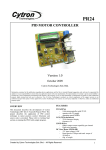
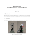
The Lynx 5 robotic arm can make fast and smooth movement, very high
accuracy and high rate of repeatability. This robot consists of rotational base,
shoulder, elbow and wrist motion, and a functional gripper that almost similar to
human arm movement. The arm includes five Hitec HS-422 servo motors, one for
the base, two for the shoulder, and one each for the elbow and wrist. An HS-81 is
included for the gripper. It was built in such solid design made from ultra-tough laser
cut Lexan structural component, black anodized aluminum servo brackets and
custom injection molded components. The assembly of this robot is easy only by
following the kit manual. This robot kit includes Lynx 5 Arm, A-base, A-Gripper
Kit, mini SSC-II Servo Controller, serial data cable, RoboMotion Software and Lynx
5 regulated Wall Pack. The image of robot is shown as figure 2.1.
Figure 2.1 Lynx 5 Programmable Robotic Arm.
The control of the robotic arm is done by using RIOS (Robotic arm
Interactive Operating System) program with the pre-assembled Mini SSC-II servo
controller. The Mini SSC-II receives positioning commands from a PC and provides
the control pulses to the servos. The DOS software is written in Quick BASIC
version 4.5. It allows user to move the arm via the keyboard, save positions to a
7
script file, single step and play the scripts back, save and load the scripts to disk. The
source code is included in ASCII so user can modify it. The RoboMotion for
Windows program allows user to teach the robot from the keyboard or joystick. The
arms gripper is positioned in an X, Y, Z grid in inches, and the moves are stored in a
spreadsheet format for easy editing [1].
2.2.2
Control of a Mitsubishi Arm Using Fiducial Tracking
This project is being done by Martin S. Mason and Laurent Coudert [2]. This
project uses a computer vision system to detect and track objects and control a
robotic arm to pickup objects routines. In industrial, the integration of computer
vision with industrial robotic arms is one of the backbones of industrial robotics.
The purpose of the vision system is to identify the object and determine its
position and orientation relative to workspace of the robotic arm. The position and
orientation output from the vision system are transformed into the workspace of the
industrial arm and then the controller of the robotic arm is used to generate a set of
joint angles for the arm.
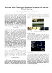
The specification of the project include Mitsubishi RV-2AJ Robotic Arm,
Custom fiducials which can be printed from this document, Python 2.6 with pyserial
and wxwidgets, Logitech Quickcam Fusion or equivalent camera, Roborealm Vision
API and Microsoft Windows Platform (98, ME, XP or Vista). A VGA resolution
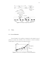
camera is required since it has fixed focus and is placed above and at an angle from
the workspace as shown in figure 2.2.
8
Figure 2.2 Overview of experimental workspace including camera, arm and
controller.
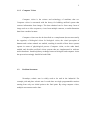
2.2.3
Cabbage Harvester
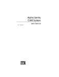
Harvesting heavy vegetables (cabbage, radish, etc.) is a labor intensive,
tedious operation. Moreover, mechanical harvesting is expected to be automated due
to a decrease in the farmer population. Some previous papers have reported about
mechanical cabbage harvesters [3] as shown as figure 2.3 in Japan (Karahashi, et al.,
1977; Kanemitsu, et al., 1993). However, due to the high standards in the Japanese
fresh markets which asks for a standard cabbage size as well as the difficulty to crop,
at the same time. The harvesters are hardly used in Japan. The aim of this research is
to automate selective harvesting by robotics approach.
The first tested prototype robot was constructed in the 1993 and tested
between 1993 and 1994 (Murakami, et al., 1995). The robot consists of a 4-link
hydraulic drive manipulator and a gripper to harvest efficiently without degrading the
quality of the product, and a machine vision system to measure the size and location
of cabbages in the field. It used to operates along the row and stops at each batch of
cabbages. Targets are evaluated by diameter of their heads which are measured by
9
image processing, and the robot arm harvests them individually. The possibility of
selective harvesting using the robotic harvester was confirmed, however, some
problems such as operation speed, accuracy and stem processing must be improved.
It is difficult to recognize the head of the cabbages because the color of the head and
leaves are almost the same, Leaves often cover the head and light conditions vary in
the field making it difficult to keep the image consistent.
Figure 2.3 Cabbage Harvester
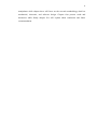
They solved the problems by developing high speed-processing algorithm
used to recognize the cabbage heads by processing the color image which is taken
under unstable light conditions in the field. The algorithm uses Neural Network to
extract the cabbage heads of the HIS transferred image, and two templates of model
cabbage. Image processing speed is enhanced by optimizing the algorithm and using
parallel processor. Figure 2.4 depict binalize and matching procedures. The location
and diameter of heads are estimated by correlation with the second template.
10
Figure 2.4 Cabbage recognition process
2.3
Theory
2.3.1
Inverse Kinematics
Inverse kinematics is the problem to determine the joint angles in term of
placing the position and orientation of the end-effecter to desired coordinates.
Consider figure 2.5 of two degrees of freedom shows below.
(x,y)
Figure 2.5 Side view for two degrees of freedom manipulator
11
The diagram is needed to derive the inverse kinematic formula for three
degree of freedom robot manipulator. Two values for angles, 𝜃1, 𝜃2 are produced
when the coordinate position,(𝑥, 𝑦) are inserted into the equations. The equations are
derived using geometric approach. This approach requires a trigonometric function to
obtain the solution of the angle. To evaluate the angle 𝜃 for−𝜋 ≤ 𝜃 ≤ 𝜋, an
arctangent function,𝑎 tan 2(𝑥, 𝑦) which returns tan−1 𝑥/𝑦 adjusted to appropriate
quadrant. Base on the theory of trigonometric, sin and cosine law used in the
diagram in Figure 2.5 equation (2.1), (2.2) and (2.3) are obtain as shown below. The
obtained equations will be use for obtaining joint1 and joint2 angle of the robot arm
in this project [4].
𝜃1 = atan 2 𝑥, 𝑦 − atan 2 ( a1 , + a2 × 𝐷 , a2 × (± 1 − 𝐷2 )) (2.1)
𝜃2 = atan 2 𝐷 , ± 1 − 𝐷2
(2.2)
Where
𝐷=
2.3.2
𝑥 2 +𝑦 2 − a 21 − a 22
2 a1a2
(2.3)
Servo Motor Analysis
Servo such as Radio Control (RC) servos usually used for remotely operating
model vehicles such as cars, airplanes, and boats. Nowadays, servos are constantly
widely used in robotics field, building humanoid robot, biologically moved robot,
robotic arm and etc. The ability of this gadget to rotates and maintains at certain
location, position or angle according to control pulses from a single wire. Inside a
typical servo contains a small motor and gearbox to make it run, a potentiometer to
measure the position of the output gear, and an electronic circuit that controls the
motor to make the output gear move to the desired position. The best part is the
entire component built is compact and cheap made it great to implement as robot
actuator.
12
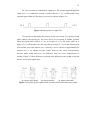
RC servo position is controlled by signal wire. The control signal through this
signal wire is a continuous stream of pulses that are 1 to 2 milliseconds long,
repeated approximately fifty times per second, as shown in figure 2.6.
Figure 2.6 Signal pulse for signal wire
The position to determine the position of the servo motor is by giving certain
pulse width to the signal wire. The servo moves to its neutral, or middle, position
when the signal pulse width is 1.5 ms as in figure 2.7 (2). The wider pulse as in
figure 2.7 (3) will turn the servo one way and as in figure 2.7 (1) for the shorter pulse
will lead the servo turn another way. Typically, a servo will move approximately 90
degrees for a 1 ms change in pulse width. However, the exact correspondence
between pulse width and servo are difference from one servo manufacturer to
another. Figure 2.7 show difference positions when difference pulse width is injected
into the servo motor signal wire.
(3) Shorter pulse width
(2) Neutral position
(1) Wider pulse width
Figure 2.7 (1), (2), (3) short pulse width, neutral position and wider pulse width
13
CHAPTER 3
METHODOLOGY AND APPROACH
3.1
Introduction
This project is divided into three parts. First part is the hardware development
that consist of the building the 3 degrees of freedom arm robot and the workspace of
the arm robot. Second part is the circuit development where this part is about the
PIC16F877A microcontroller with multi UART, servo motor controller (SC16A),
power distribution circuit and the interface device for the project. Lastly, the third
part is the software development that consists of the software programming of the
microcontroller and the image processing software process of the project. Figure 3.1
shows the complete design of the system.
14
Figure 3.1 Completed system design
3.2
Hardware Development
3.2.1
Robotic Arm Design
The robotic arm structure will emulate industrial robotic arm. The initial
concept in hardware design is based on the market available small robotic arm design
as shown in topic 2.2.1 of literature review. The difference is for this particular of
project, the robotic arm will consist only have 3 joints, 2 links and end-effecter. That
makes it a 3 degrees of freedom robotic arm compare to the arm robot in figure 2.1 in
topic 2.2.1 that got 5 degrees of freedom. This robotic arm is built so that it has a
15
right arm configuration so that it match for the equations that been discuss in inverse
kinematic topic 2.3.1.
The robotic arm will be made so that in can do a pick and place routines that
mean it can grip an object and move around it joints. The components used in the
hardware structure construction are made cheap and affordable. This structure of the
links of the robot arm will be constructed using simple materials which is Perspex
that are easy to fabricate and worked on. Perspex also knows as acrylic is a hard
plastic base material that is suitable for hardware use. However as for the gripper, the
material use is “U” shape aluminum. The actuator used in every joint for this robot
arm is RC servo motor.
3.2.1.1RC Servo Motor
Servo is an automatic device that uses error-sensing feedback to correct the
performance of a mechanism. For this project, RC servo has been chosen to be used
as actuator for the robot manipulator. The reasons for choosing RC servo motor are
due to their affordability, reliability, and simplicity of control by microprocessors,
RC servos are often used in small scale robotics applications. Moreover, this small
type of actuator got very powerful torque to do heavy duty lifting.
These RC servos are composed of an electric motor mechanically linked to a
potentiometer. Pulse-width modulation (PWM) signals sent to the servo are
translated into position commands by electronics inside the servo. When the servo is
commanded to rotate, the motor is powered until the potentiometer reaches the value
corresponding to the commanded position. Figure 3.2 shows the type of selected
servo motor.
16
Figure 3.2 Selected servo motor
The specifications of this servo motor are:
i.
Full Metal Gear and heavy duty
ii.
Speed (sec/60deg): 0.22/4.8V, 0.20/6.0V, 0.17/7.2V
iii.
Torque (Kg-cm): 9.0/4.8V, 11.0/6.0V, 13.0/7.2V (maximum 7.2V)
iv.
Pulse width range: 0.582ms to 2.5ms (estimation)
v.
2 Ball Bearings Designed for "closed feedback".
vi.
Able to control the position of the motor
vii.
Size (mm): 40.8x20.18x36.5 and Weight 55g
There are 5 servos used for this project robotic arm. All five servos are used
for the robot manipulator control. The first servo is attached at the base of the
manipulator. This servo will control the rotating base the arm robot. Two servos are
used for the first joint. This is because the robot manipulator is quite heavy and need
more torque to support joint2 that used 1 servo and the gripper of the robotic arm that
also used 1 servo motor.
17
3.2.2
Robotic Arm Workspace
In industrial, robot that entirely automated and semi-automated operation
often got it workspace call as “robot work cell. All the devices in the work place
have to be adjusted when the robot introduced into the workspace. The workspace is
created because it may be dangerous if the robot is in operating mode in case if there
is failure occurs.
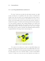
For this project, the robot arm itself will be place in its own workspace
together with an overhead webcam camera. The workspace is design base on the
horizontal and vertical reach of the robotic arm. The horizontal reach is determined
by inner reach and outer reach of the arm robot. Inner reach mean the minimum
reach of the robot arm can go and etcetera for the outer reach for the robot arm. As
for the vertical reach, it determines by the size of the ball that the robot arm will be
picking in this project. The ball will be place only on the floor of the workspace.
Base on the horizontal, vertical, inner and outer reach of the robot arm, the space for
the arm robot workspace is in spherical plane type. The plane is shown in figure 3.3
(1), (2).
(1)
18
(2)
Figure 3.3 (1)(2) Horizontal reach and Vertical reach
The overhead webcam will be placed above the workspace of the robotic arm
so that it can capture the whole sector of the robot arm spherical type plane. The
height of the webcam positioned above the workspace is universal depending on the
wide angle of the camera, the pixel of the camera and also quality type of the image
the camera can capture as long as the whole workspace can be seen.
3.3
Circuit Development
3.3.1
Microcontroller
3.3.1.1 PIC16F877A
This powerful 200 nanosecond instruction execution yet easy-to program
CMOS FLASH-based 8-bit microcontroller produce by Microchip Technology Inc
[6] provided a seamless migration path of software code to higher levels of hardware
integration. The PIC 16F877A features a 'C' compiler friendly development
environment,
256
bytes
of
EEPROM,
Self
programming,
an
ICD,
2
19
capture/compare/PWM functions, 5 channels of 10-bit Analog-to-Digital (A/D)
converter, the synchronous serial port can be configured as either 3-wire Serial
Peripheral Interface (SPI™) or the 2-wire Inter-Integrated Circuit (I2C™) bus and
Universal Asynchronous Receiver Transmitter (UART).
All of these features make it ideal for manufacturing equipment,
instrumentation and monitoring, data acquisition, power conditioning, environmental
monitoring, telecom and consumer audio/video applications. The microcontroller has
five port namely Port A, Port B, Port C, Port D and Port E. All ports are bidirectional
I/O port, meaning that each port can be used as input or output port depending on the
user. Port B can also be software programmed for internal weak pull-up on all input.
The features of PIC16F877A are:
i.
40pin package(PDIP)
ii.
14bit core – 35 instructions
iii.
200ns instruction time(20Mhz)
iv.
8k 14bit FLASH program memory
v.
368 8bit data memory or register (“File registers”)
vi.
256 8bit EEPROM (nonvolatile) data registers
vii.
8 level hardware stack (interrupts enabled)
viii.
33 GPIO (20mA source / 25mA 7sink)
ix.
Peripherals: 5ch 10bit ADC, UART/I2C/SPI, PWM, 16bitand 8bit
timers/counters
x.
ICSP and Bootloader capability
The reason for choosing this PIC microcontroller is because of the existence
of the UART terminal. The terminal is very important for this project because the
terminals play the most important part in purpose of moving the robot arm servo
motor actuator. The UART terminals which are PORTC6 and PORTC7 are used as
communication platform with Servo Controller 16 Channels (SC16A) by sending
and receive servo pulse width. This servo controller is used to control the angle of
the servo for the robot manipulator.
PIC16F877A only got single UART terminal that can be used. If we look
back in figure 3.1 in introduction topic 3.1, this project used another one UART
20
terminal where it is used for communication between the microcontroller and the
computer. It is for receive and sending the data from the image processing part in the
computer. However, this problem can be solved by adding one programmable
external UART terminal that is program into the microcontroller. This multi UART
configuration will be discussed in the next topic.
3.3.1.2 External UART Connection
The start board for this PIC16F877A in this project is done by using a start-up
kit call SK40C produce by Cytron Technologies Inc [7]. This kit is an enhanced 40
pins PIC microcontroller used to interface between applications by directly plugging
in the I/O in whatever way that is convenient. However for this project, it has been
modified for the use of another one UART configuration that used PORTC2 and
PORTC3 as the external UART.
This external UART is created based on programming to make it functions as
UART characteristic. The external UART is designed for interface using a standard
system protocol programming and it will be discuss later in Software development
topic. This method also can be learned through document done by Cytron
Technologies Inc [8]. Figure 3.4 shows the schematic for the complete
microcontroller circuit with external UART.
21
5 Volt voltage
regulator.
Crystal 20Mhz
Internal UART
External UART
Figure 3.4 Complete schematic for microcontroller
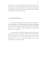
3.3.2
Servo Motor Controller (SC16A)
SC16A in figure 3.5 (1), (2) have offers reliable yet user friendly RC Servo
motor controller to hobbyist and students. It is designed to control 16 independent
standard RC (Remote Control) servo motors simultaneously in a single board. For
this project, it is used for drive the servo motor movement by receiving command
from the microcontroller. All five actuators in the robotic arm will be control by this
drive circuit board. Each servo signal pin is able to generate servo pulses from 0.5 ms
to 2.5 ms, which is greater than the range of most servos, further allows for servos to
operate 180 degrees controlling the servo motor angle. The host of SC16A is
connected through microcontroller with UART interface. This UART interface
presents a flexible, fast and easy to use feature. It is designed with capabilities and
features of:
i.
16 channels: Servo driven independently.
22
ii.
Extendable to 32 Channels: Two controller linked together to drive 32
servos.
iii.
Optional Position Reporting: User may request position of an
individual servo.
iv.
Optional Servo Ramping: Choose one of 63 ramp rate (speed rate) for
each servo.
v.
Resolution: 1.367us.
vi.
Servo pulse: 0.5ms to 2.5ms.
vii.
Dimension: 8.2cm x 4.7cm
Figure 3.5 (1) Board layout of SC16A
Figure 3.5 (2) Explanation for the SC16A
In order to connect SC16A to Microcontroller, the minimum requirements are
the microcontroller must have Universal Asynchronous Receiver and Transmitter
(UART Terminal) and 5 Volt. 5V will not be an issue since most of embedded or
microcontroller system is 5V powered, tapping the 5V from host system will be
reasonably easy. As for UART, a minimum of Transmit pin is required to send
23
command to SC16A. Figure 3.6 below show the connection between microcontroller
and SC16A.
Figure 3.6: Connection between SC16A and Microcontroller
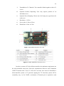
3.3.2.1 Current Booster Circuit
This current booster circuit is main one of the main part in this project [9]. It
is used to supply voltage and also current to each of servo motor in the actuator.
Voltage regulators used is LM7806 that provide output voltage of 6 volt sometimes
need to provide a little bit more current then they actually can handle.
A power transistor such as the TIP2955 is used to boost the extra needed current
above the maximum allowable current provided via the regulator. Current up to
1500mA (1.5ampere) will flow through the regulator, anything above that makes the
regulator conduct and adding the extra needed current to the output load. Both
regulator and power transistor must be mounted on an adequate heat sink because
actuator such as RC servo motor consumed very high current to operate thus make
both these component really hot. The input for this circuit will be from 12V and 2A
adapter DC source. While the output of 6V and approximate 3A current will be
24
connect to SC16A servo motor power source. The schematic of the circuit is shown
in figure 3.7.
Figure 3.7 The Current Booster schematic circuit
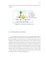
3.3.3
USB to UART Converter (UC00A)
The interface between device such as between microcontroller and computer
nowadays is widely being used known as Serial communication. UART is one of
those serial interfaces. In past days, most serial interface from microcontroller to
computer is done through serial port (DB9). However, since computer serial port
used RS232 protocol and microcontroller used TTL UART, a level shifter is needed
between these interfaces. But nowadays, serial port of computer have been phase out,
it have been replaced with USB. Of course most developer chooses USB to serial
converter to obtain virtual serial port. The level shifter is still necessary for UART
interface. Thus, Cytron Technologies Inc decided to develop a USB to UART
converter which offers USB plug and play, direct interface with microcontroller and
it provide low current 5V supply from USB port [10].
25
This project needs this kind interface because data need to be send and
receive between computer and microcontroller. At the microcontroller part,
connection will be connecting to the external UART terminal that is discuss in topic
3.3.1.2 while the other side will be connect to the USB port of the computer.UC00A
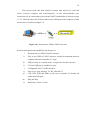
connection is visualized in figure 3.8.
Figure 3.8 Connection for USB to UART converter
It has been designed with capabilities and features of:
i.
Develop low cost USB to UART converter
ii.
Easy to use USB to UART converter, aiming development between
computer and microcontroller, 5V logic.
iii.
USB powered, no external source is required to use this converter
iv.
5V from USB port is available for user.
v.
Configurable for 5V UART interface.
vi.
Easy to use 4 pin interface: Tx, Rx, Gnd and 5V.
vii.
CTS, RTS, DTR and DSR is pull out to standard 2x5 header pin
solder able PCB pad.
viii.
ix.
Plug and Play
Dimension: 4.6cm x 1.8cm
26
3.4
Software Development
The system software plays an important role in this system. Without it, the
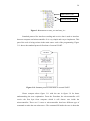
whole project cannot operate. Thus, the program flowchart of the system is as shown
in figure 3.9.
Figure 3.9 Project programming flowchart
The program mostly focuses on 2 parts which is in computer part and
microcontroller part. Computer part consists of image processing, calculating the
inverse kinematics and data sending and receive protocol. While microcontroller act
as intermediate system to receive data from computer and send it to servo motor
controller after that data being process. It also sends feedback to computer after each
set data is done processed.
27
3.4.1
MPLAB IDE
MPLAB Integrated Development Environment (IDE) is a free, integrated
gcc-based toolset for the development of embedded applications employing
Microchip's PIC. The MPLAB IDE runs as a 32-bit application on Microsoft
Windows, and includes several free software components for application
development, hardware emulation and debugging. MPLAB IDE also serves as a
single, unified graphical user interface for additional Microchip and third-party
software and hardware development tools.
Both Assembly and C programming languages can be used with MPLAB
IDE. Others may be supported through the use of third party programs. Support for
MPLAB IDE, along with sample code, tutorials, and drivers can be found on
Microchip's website. MPLAB IDE does not support Linux, UNIX, or Macintosh
based operating systems.
The microcontroller used in this project is being program using C-language.
Programming in this part is consist of external UART programming and servo motor
controller (SC16A) programming.
3.4.1.1 External UART Programming
Once again, the microcontroller is already modified by adding 1 external
UART terminal. The external UART terminal needs to be program so that it can
function as UART terminal. The programming consists of special library to function.
Some header files call “uart_io.h” and source files call “uart_io.c” need to be
included inside the programming structure before this external UART protocol can
be used. Please refer to appendix for better understanding. Figure 3.10 shows the
location to of the 2 special library codes.
28
Main source code
Special library codes
Figure 3.10 Position for uart_io.h and uart_io.c
Standard protocol for interfaces sending and receive data is used to interface
between computer and microcontroller. It is very simple and easy to implement. This
part of the code is being written in the main source code of the programming. Figure
3.11 shows the standard protocol flowchart of external UART.
Figure 3.11 Standard protocol flowchart of external UART
Please compare above figure 3.11 with the one in figure 3.9 for better
understanding the next explanation. From the flowchart, the microcontroller will
receive the first byte from computer which it will choose case inside the
microcontroller. There are 12 cases to microcontroller that have different type of
command to make the arm robot move. The command fill inside the case is about the
29
protocol to send data to servo motor controller. This is the part when the second
bytes of data being send as in this case the type of data send is in form of the angle of
the joint that will be process to be sent to the servo motor controller. Lastly, the
microcontroller will write to the computer a byte of data just for confirm that the
routines in the case already done. This process will be process until no sending and
receive data being made.
3.4.1.2 SC16A Programming
The SC16A will control movement of the servo motor base on the right
protocol. The protocol is important to send command to SC16A which will control a
particular servo to a position with a defined speed. Second protocol is for host to
request the current position of servo. The second protocol is alternative to user, if
position reporting is not a requirement. In this project it can be ignored. A packet of
4 bytes must be sent in order to control each servo. The four bytes are:
i.
First byte: Start byte + Servo motor number.
ii.
Second byte: Position (Higher 6 bit)
iii.
Third byte: Position (Lower 6 bit)
iv.
Fourth byte: Speed
Table 3.1 The specific value for each byte.
30
The SC16A will translate four bytes of data into three parameters:
i.
First byte is combination of start bit and servo number. The 6th bit must be
“1” to indicate this byte is first byte of SC16A command.
ii.
Second and third byte combined to provide 12 bit data of servo position. 01463 equivalent to 0-180 degrees. The microcontroller will receive data in
term of angle from the microcontroller. So the microcontroller must convert
this value to servo position value. The resolution of SC16A is 1.367us. It will
start from 0.5ms and increase the duty cycle of pulses to the maximum till
2.5ms. That mean the pulse width is equal to 2.5ms minus 0.5ms makes that
2.0ms. The maximum angle is depending on servo motor used that is
180degrees. All this information is base on characteristic of RC servo motor
that being used in this project. Thus, following formula show the derivation
for servo position to angle relationship:
Servo pulse = (resolution x servo position) + (min servo pulse)
((angle )x(pu lse width ))
Servo pulse = (min servo pulse) + (maximum
angle movement )
(3.1)
(3.2)
Compare both (3.1) and (3.2) equation
2(angle )
Servo position = 1.367μ(180°) ≈ 8 x angle
(3.3)
31
iii.
Forth byte represents the speed of servo rotation.
Forth byte determines the speed of servo rotation for each servo
independently. The higher value, the faster servo will rotate to its Position. However,
value of „0‟ will disable the speed, thus provide normal speed, the servo motor will
rotate according to its own maximum speed. 63 ramp rates allow the user to set the
speed of each servo. Decimal value „1‟ indicates that the servo will run at slowest
speed and decimal value „63‟ will run at fastest speed. At each 20ms interval, the
current servo position will increase or decrease with the speed value depending on
whether the position is greater or lesser than the new position.
3.4.2
RoboRealm
RoboRealm is an application for use in computer vision, image analysis, and
robotic vision systems [12]. It is easy to be obtained and install to the computer
system. Just by using an easy point and click interface RoboRealm simplifies vision
programming. There is no need to write such long code for process the image and it
can save much time. Using RoboRealm user can create a low cost vision software
solution with a standard webcam that allows user to explore the very complex world
of image analysis and image processing. Through an easy to use analysis pipeline
user can add image processing filters to translate an image into robotic movements or
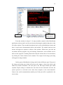
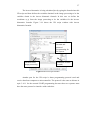
computer actions for user vision-guided robotic projects. Figure 3.12 show window
of RoboRealm software:
32
Video image
window (output)
Modules.
Figure 3.12 RoboRealm Window
Modules that
being choose.
From the window in figure 3.12, many modules contain in this RoboRealm
application software and it can be used just by choosing the modules that place at the
left of the window. These module description can be refer in RoboRealm website and
there is much more documentation about each module. The module that has been
chosen will appear in sequence at below of the window. When done, just click the
run button and the program is up and running. Furthermore, more modules can be
add even the program is running. But before that the webcam has to be switched on
by clicking the camera button in the window. The output of the image processing
will appear in image window.
In this project, RoboRealm is being used for three difference part. First part is
the image processing part which will process the image to detect the object and
obtain its position coordinate. The next part is the VB script module part which
explains simple coding to calculate the arm robot inverse kinematic and also the
system protocol to send and receive data from computer to the microcontroller.
Lastly is the serial communication module part. Each part will be explained in the
next section.
33
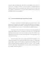
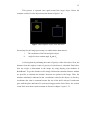
3.4.2.1 Image Processing
Image processing is the part that acts as the “Robotic Arm” eyes caught from
the overhead webcam. First step in this image processing is to detect the object
which is an orange ball. The ball needs to be griped by the arm robot and to detect
the placed in a blue target. Figure 3.13 shows the initial image of the system caught
by the overhead webcam camera before being processed.
Ball
Target
Figure 3.13 Initial view of video image
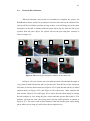
This process will be done one step at a time starting from the ball detection
followed by the target through object color detection. The RGB filter module will be
used to filter the base color for the ball and target. In this case, RGB yellow base and
RGB blue base is being filter from the image. The RGB filter yellow base is used to
filter the ball color while RGB filter blue base is used to filter the target color.
To make sure the color detection is smooth, several modules are being used
after the RGB filtering such as blob size, erode, fill and lastly the smooth hull
module. Blob size is a process where the image will only capture the biggest area of
34
object being filtered. The same procedure will be carried for the target image
processing. Figure 3.14 shows the result after the blob size module process.
Figure 3.14 Blob size result
Next, erode module will deduct 1 pixels at the edge of the detected image to
make it smoother. Then fill module will filled the hole in the detect object image.
Finally smooth hull module will produce the perfect image of detected object. Figure
3.15 shows step by step result for smoothing the image.
Figure 3.15 Smoothing process result
35
This process is repeated once again toward the target object. Hence the
complete results of color object detection shown in figure 3.16.
Figure 3.16 Complete object color detection
Second step for the image processing is to obtain below data such as:
i.
The coordinate of the ball and place object.
ii.
Angle for base rotation angle 𝜃3 and 𝜃4
It is being done by obtaining the center of gravity of the each object. Next, the
distance from the origin to center of gravity of each detect is calculated. But before
that, the origin is determined in the image by using display point modules in
RoboRealm. To get the distance in the image, Roborealm calculate distance module
are provides to calculate the distance between two points in the image. Thus, the
distance calculated is indicated as the x coordinates value for the objects. As for the y
coordinates the value is constant because the size of the ball is always fix and same
goes with the place and both of it is always being put on the floor. Hence, the vertical
reach of the arm robot remain constant as discuss in chapter 3 topic 3.2.2.
36
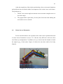
To obtain the angle 𝜃3 and 𝜃4 the blue line and also the line between origin
and each object is done by using display line module in RoboRealm. Then, the
calculate angle modules is used to calculate the angle between the lines. Figure
3.17(1) show complete image processing result and figure 3.17 (2) shows the 3
dimensional results in real world view.
Figure 3.17(1), (2) Results for Image Processing
3.4.2.2 VB script
This is one of the RoboRealm applications where the VB Script module
provides a way to create custom Visual Basic scripts that can be used to process
image statistics and map then toward servo/motor values. This module is intended to
be used as a way to quickly perform custom operations without needing to
implement a Plugin or use the API which typically requires external tools.
This VB script list all the data obtained in the image processing and process
as variables. In this project, the script mainly consists of two major parts. First part is
to calculate the inverse kinematic to obtain each joint angle 𝜃1, 𝜃2 . The second part is
the main function of the programming that acts as the protocol to send and receive
data from computer to the microcontroller.
37
The inverse kinematics is being calculated just by typing the formula into this
VB script and then defines the variables obtained in the image processing to be the
variables obtain in the inverse kinematic formula. In this case we define the
coordinate (x,y) from the image processing to be the variables for the inverse
kinematics formula. Figure 3.18 shows the VB script window with inverse
kinematics formula.
Inverse kinematics
formula and
protocol
programming for
the system
Variables from
image processing.
Modified variable.
(result)
Figure 3.18 VB script Window
Another part for the VB script is about programming protocol send and
receive data form computer to microcontroller. The protocol is the same as discuss in
topic 3.4.1.1 for the external UART programming because these two systems must
have the same protocol to interface with each other.
38
3.4.2.3 Serial Communication
The serial module is used to communicate from RoboRealm to serial based
controllers. This module actually the part where send and receive data happens
between the computer and microcontroller. In other word, it connect computer to the
microcontroller. The angles obtained in VB script is send to the microcontroller via
this serial communication. The sequence data send depends on the protocol in the
VB script. Figure 3.19 shows the window of the serial communication.
Figure 3.19 The Serial Communication window
The green line number indicate the data being send to the microcontroller
while the red line number is the feedback data receive from the microcontroller to
indicate that the routines is already done in the microcontroller. The green line has
two numbers for instance “1 1” because according to the protocol, the first number is
the first byte being send as case number and the second number is the second byte
being send as joint angles. After that the red number appears means the
microcontroller send back the feedback.
39
CHAPTER 4
RESULTS AND DISCUSSION
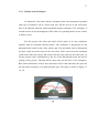
4.1
Robotic Arm and Its Workspace
The robotic arm and its workspace after completion are shown in figure 4.1.
The robotic arm has 3 degrees of freedom that consist of three joints, 2 links and 1
end-effecter. Each of the joints has limit of 180 degrees of rotational angle based on
the RC servo motor limit angle that have been used. This arm robot used 5 RC servo
motor to drive it that is 1 RC servo at joint1, joint3 and gripper while 2 RC servos at
joint2. The workspace of the robotic arm was developed base on the maximum and
minimum reach of the robotic arm. The overhead webcam is placed above the
workspace for viewing the whole system workspace and act as the eyes of the robot
arm.
40
Figure 4.1 Complete robot arm and its workspace
The gripper for the arm robot made of aluminum that consists of 2 fingers to
grip an object. Its mechanical movement is base on pulls methods in this case the
spring will be used to pull the gripper back into its initial condition. While for the
gripper to move into gripping position, the string attach to the RC servo will pull
against the spring force for the gripper open to grip an object. Figure 4.2 (1), (2) will
show clearly the movement of the gripper before and after its grip.
Springs is pull to
keep the gripper
close
(1) Before Grip
String is pull by the
RC servo to keep the
gripper open.
(2) After Grip
Figure 4.2 (1), (2) Before and after gripping
41
After the completion of the robotic arm hardware, there exist some limitations
and problems that can hinder further development of the robotic arm in the future.
The problems are:
i.
The RC servo motor angle movements are not accurate enough to move to
the desire angle.
ii.
The gripper built is quite heavy for the joint of the arm robot making the
movement is not so smooth.
4.2
Robot Inverse Kinematics
For the robot kinematics, the equation used is same as the equations discussed
in robot inverse kinematics in topic 2.3.1. But the only different is this arm robot
used elbow up configuration. Coordinates of (x,y) is insert into the formula to obtain
the angles 𝜃1, 𝜃2 of each joints. Figure 4.3 shows the arm robot with its free body
diagram.
Figure 4.3 The arm robot with it free body diagram
42
4.3
Circuitry
The circuit system used in this project is the microcontroller board with servo
motor controller that drive the RC servo motor that power by the current booster
circuit. This microcontroller circuit used 2 UART terminals that is internal UART
terminal and external UART terminal. The internal UART terminal used to send and
receive data from or to the servo motor controller. While external UART terminal
that is programmable UART terminal is used to send and receive data from or to
computer using USB to UART converter as intermediate device between the
computer and microcontroller. The external UART terminal is made because for this
type of PIC16F877A only have 1 UART configuration in it. Figure 4.4 shows the
complete circuit for the system:
Servo motor
controller(SC16A).
Current booster to
supply the servo
motor.
Microcontroller with
PIC16F877A.
Internal UART
to SC16A.
External UART to
computer using
USB to UART
converter.
Figure 4.4
The complete circuit system
43
4.4
Pick and Place Routines
When the hardware and circuits are assembles to complete the system, the
RoboRealm software will be set up and run. Now the real result can be obtained. The
system will be in initialize position as long as there is no ball being put in the robot
workspace or the ball is already inside the place object. By the time the ball is put
separate from the place object; the system will run the pick and place routines as
shown in figure 4.5.
1
5
4
3
2
6
7
Figure 4.5 Result on pick and place routines of the robot arm
In Figure 4.5(1) the robotic arm is in initial position will calculate the angle of
every joint for both ball and the place to put the ball. Then the base of the robot arm
will rotate to face the ball as shown in Figure 4.5(2) to pick the ball and stay in initial
position shown in Figure 4.5(3) and Figure 4.5(4) respectively. After complete the
pick routine, Figure 4.5(5) and Figure 4.5(6) shows that the robot doing its placing
the ball routines by first facing the place object and then put the ball inside it. The
routines end with the arm robot being back into the initial position as shown in
Figure 4.5(7). The same result will be obtained if the ball and the place object being
put in others area as long as it still in the robot workspace area.
44
CHAPTER 5
CONCLUSION AND RECOMMENDATION
5.1
Conclusion
Overall of the project objective has success and provides a good testing
background for academic learning such as robot kinematics, programming and
hardware assembly. This is partially due to the limited resources available in the
laboratory for the student to implement such systems. There lots of knowledge
obtained in doing this project as well as practical hands-on involved during the
process.
Further research need to be done so that there will be improvement in our
industrial throughout the country because as we can know our technology are far
behind compare to the developed country that have lot robotics arm used in large
manufacturing plant.
45
5.2
Recommendation
There are numbers of possible improvements to be carried out in the future:
i.
For hardware design. The use of RC servo cause inaccuracy in
moving angles in kinematics. Some modification can be implemented
such as using advanced motor that more flexible, accurate and precise
in its movement (digital servo, stepper).
ii.
More advanced image processing. Color detection implementation is
still classified as simple task. The host application can be improved to
add more functionality such as object recognition.
iii.
Simple circuitry usage. This project used microcontroller as
intermediate part of the system. The system perhaps can be improved
by sending data straight from computer to servo motor controller or
other motor operating drive system to reduce the cost of the project.
iv.
The supply source for the system. A stable and high current source
can make this system operating much smoother.
46
REFERENCES
[1]
HOBBYTRON, http://www.hobbytron.com/lynx-arm.html
[2]
profmason.com, http://profmason.com/?p=1173
[3]
http://www.cryo.affrc.go.jp/sougou/kikai/member.files/97biorobotics.pdf
[4]
Dr. Johari Halim Shah Osman, 2009, Brief Note On Robotic 4th
Edition.Faculty of Electrical Engineering, Universiti Teknologi Malaysia.
[5]
RC Servo C36R, C40R, C55R User's Manual V1.0,Apr 2009,Cytron
Technologies Inc
[6]
PIC16F87XA Data Sheet, 2003. Microchip Technology Inc
[7]
SK40C Enhanced 40 pins PIC Start-up Kit V1.2,Dec 2010,Cytron
Technologies Inc
[8]
Multi UART Interface V1.0, July 2009, cytron Technologies Inc
[9]
http://www.extremecircuits.net/2009/08/ampere-or-current -boostercircuit.html
[10]
Cytron USB to UART Converter UC00A User's Manual V1.1,August
2009,Cytron Technologies Inc
47
[11]
SC16A Servo Controller User’s Manual V2.1, 2008. Cytron Technologies Inc
[12]
RoboRealm, http://www.roborealm.com/index.php
48
APPENDIX A
Main source code for PIC16F877A
//
include
//=======================================================================
#include <pic.h>
//
configuration
//=======================================================================
__CONFIG ( 0x3F32 );
//configuration for the microcontroller
#include "uart_io.h"
//
define
//=======================================================================
#define SW1
RB0
#define SW2
RB1
#define led1
#define led2
RB6
RB7
#define servo1a
#define servo1b
#define servo2
#define servo3
#define servo4
0x42
0x45
0x48
0x4B
0x4F
//led 1 (active high)
//led 2 (active high)
//1st link
//1st link
//2nd link
//gripper
//base
//chanel = 2
//chanel = 5
//chanel = 8
//chanel = 11
//chanel = 15
//
global variable
//=======================================================================
static volatile unsigned int received_servo_position[0x11];
int k=0;
int m=0;
//functionprototype
//=======================================================================
void init(void);
void send_cmd(unsigned char num, unsigned int data, unsigned char ramp); //UART transmit 4 bytes:
servo number, higher byte position, lower byte position and speed
void delay(unsigned long data);
//delay function, the delay time
void uart_send(unsigned char data);
//UART transmit
unsigned char uart_rec(void);
//UART receive
//initialization
//=======================================================================
void init()
{
//set IO port for led and switch
TRISC = 0b00000000;
//set input or output
TRISB = 0b00000011;
//1=input,0=output
TRISD = 0b00000000;
ADCON1 = 0x06;
//set port A as digital I/O
//setup UART
BRGH = 1;
SPBRG = 129;
SPEN = 1;
RX9 = 0;
TX9 = 0;
CREN = 1;
//baud rate low speed option
//set boud rate to 9600bps, 64 for 10Mhz crystal; 129 for 20MHz crystal
//enable serial port
//8-bit reception
//enable reception
49
TXEN = 1;
//enable transmission
//initial condition
led1=0;
led2=0;
//led1 is off
//led2 is off
send_cmd( servo1a, 1100, 63);
send_cmd( servo1b, 1100, 63);
delay(200000);
send_cmd( servo2, 213, 63);
delay(200000);
send_cmd( servo4, 731, 63);
delay(200000);
send_cmd( servo3,1454, 63);
delay(200000);
send_cmd( servo3,800, 63);
delay(200000);
send_cmd( servo3,1454, 63);
delay(200000);
uart_init(1);
unsigned char data_to_read=0;
unsigned char j;
//initialize UART1
uart_write(1,9);
}
//
main function
(main fucntion of the program)
//=======================================================================
void main(void)
{
init();
//uart_init(1);
unsigned char data_to_read=0;
//unsigned char j;
//uart_write(1,0);
while(1)
{
//if function
data_to_read=uart_read(1);
//initialize UART1
//read first byte from UART1
switch(data_to_read)
{
case 1:
data_to_read=uart_read(1);//read second byte from UART1
if(data_to_read==0)
{
led1=0;
//detect to ON or OFF led1
send_cmd( servo3,1454, 63);
delay(200000);
send_cmd( servo3,800, 63);
delay(200000);
send_cmd( servo3,1454, 63);
delay(400000);
}
else if(data_to_read==1)
{
led1=1;
send_cmd( servo3,1454, 63);
50
delay(200000);
send_cmd( servo3,800, 63);
delay(200000);
send_cmd( servo3,1454, 63);
delay(400000);
}
uart_write(1,0);
break;
case 2:
data_to_read=uart_read(1);
if(data_to_read==0)
{
led2=0;
//detect to ON or OFF led2
init();
delay(300000);
}
else if(data_to_read==1)
{
led2=1;
init();
delay(300000);
}
uart_write(1,'a');
break;
case 3:
data_to_read=uart_read(1);
send_cmd(servo4 , data_to_read*8 , 63);
delay(200000);
uart_write(1,1);
break;
//base
case 4:
data_to_read=uart_read(1);
send_cmd(servo2 , data_to_read*8 , 63);
delay(200000);
uart_write(1,2);
break;
//joint2
case 5:
data_to_read=uart_read(1);
send_cmd(servo1a , data_to_read*8 , 63);
send_cmd(servo1b , data_to_read*8 , 63);
delay(200000);
uart_write(1,3);
break;
//joint1
case 6:
data_to_read=uart_read(1);
send_cmd(servo3 , data_to_read*8 , 63);//gripper
delay(200000);
uart_write(1,4);
break;
case 7:
data_to_read=uart_read(1);
send_cmd( servo1a, 731, 63);
send_cmd( servo1b, 731, 63);
delay(200000);
send_cmd( servo4, 110, 63);
delay(200000);
630 to grip
51
send_cmd( servo2, 520, 63);
delay(200000);
send_cmd( servo1a, 250, 63);
send_cmd( servo1b, 250, 63);
delay(200000);
send_cmd( servo3,1454, 63);
delay(200000);
uart_write(1,5);
break;
case 8:
data_to_read=uart_read(1);
send_cmd( servo1a, 1200, 63);
send_cmd( servo1b, 1200, 63);
delay(200000);
send_cmd( servo2, 213, 63);
delay(200000);
send_cmd( servo4, 731, 63);
delay(200000);
uart_write(1,5);
break;
case 9:
data_to_read=uart_read(1);
send_cmd(servo4 , data_to_read*8 , 63);
delay(200000);
uart_write(1,6);
break;
//base
case 10:
data_to_read=uart_read(1);
send_cmd(servo2 , data_to_read*8 , 63);
delay(200000);
uart_write(1,7);
break;
//joint2
case 11:
data_to_read=uart_read(1);
send_cmd(servo1a , data_to_read*8 , 63);
send_cmd(servo1b , data_to_read*8 , 63);
delay(200000);
uart_write(1,8);
break;
//joint1
case 12:
data_to_read=uart_read(1);
send_cmd(servo3 , data_to_read*8 , 63);//gripper
delay(200000);
uart_write(1,9);
break;
630 to grip
}
}
}//main loop
//subroutine
//=======================================================================
//servo subroutines
void send_cmd(unsigned char num, unsigned int data, unsigned char ramp)
//send 4 bytes of
command to control servo's position and speed
{
unsigned char higher_byte=0, lower_byte=0;
//servo channel should start with 0b01XX XXXX
52
//therefore needs to change to 0x41-0x60
num=num|0b01000000;
//position value from 0-1463 are greater than a byte
//so needs two bytes to send
higher_byte=(data>>6)&0x003f; //higher byte = 0b00xxxxxx
lower_byte=data&0x003f;
//lower byte = 0b00xxxxxx
uart_send(num);
//First byte is the servo channel 0x41-0x60
uart_send(higher_byte);
//second byte is the higher byte of position 0b00xxxxxx
uart_send(lower_byte);
//third byte is the lower byte of position 0b00xxxxxx
uart_send(ramp);
//fourth byte is the speed value from 0-63
}
//UART subroutines
unsigned char uart_rec(void)
{
unsigned char rec_data;
while(RCIF==0);
rec_data = RCREG;
return rec_data;
}
void uart_send(unsigned char data)
{
while(TXIF==0);
TXREG=data;
}
//delay subroutine
void delay(unsigned long data)
{
the given value
for( ;data>0;data-=1);
}
//receive uart value
//wait for data
//return the received data
//only send the new data after
//the previous data finish sent
//delay function, the delay time
//depend on
53
APPENDIX B
Header file code for external UART in PIC16F877A
//
include
//=======================================================================
#include <pic.h>
//
define system crystal frequency
//=======================================================================
#define _XTAL_FREQ 20000000
//frequency of the crystal
//UART configuration
//=======================================================================
#define UART_1_tx
RC2
//define which pin is used for build TX
of UART1
#define UART_1_tx_tris
TRISC2
#define UART_1_rx
RC3
//define which pin is used for build RX
of UART1
#define UART_1_rx_tris
TRISC3
#define UART_1_baudrate
9600
//define the baudrate of this UART channel
//
function prototype
//=======================================================================
===
//the function of initialize UART
void uart_init(unsigned char channel);
//the function of write
void uart_write(unsigned char channel,unsigned char data);
//the function of read
unsigned char uart_read(unsigned char channel);
54
APPENDIX C
Additional source file code for external UART in PIC16F877A
//
include
//=======================================================================
#include "uart_io.h"
//
unused uart channel handler
//=======================================================================
unsigned char dummy_byte=0;
#ifndef UART_1_tx
#define UART_1_tx dummy_byte
#endif
#ifndef UART_1_tx_tris
#define UART_1_tx_tris dummy_byte
#endif
#ifndef UART_1_rx
#define UART_1_rx dummy_byte
#endif
#ifndef UART_1_rx_tris
#define UART_1_rx_tris dummy_byte
#endif
#ifndef UART_1_baudrate
#define UART_1_baudrate 9600
#endif
//
baudrate cycle definition
//=======================================================================
#define UART_1_baudrate_cycle (_XTAL_FREQ/4)/UART_1_baudrate
//
functions
//=======================================================================
void uart_init(unsigned char channel)
{
switch(channel)
{
case 1:
UART_1_tx=1;
//set tx pin to '1'
UART_1_tx_tris=0;
//set tx pin as output
UART_1_rx=1;
//set rx pin to '1'
UART_1_rx_tris=1;
//set rx pin as input
break;
}
}
void uart_write(unsigned char channel,unsigned char data)
{
unsigned char i;
switch(channel)
{
case 1:
UART_1_tx=0;
_delay(UART_1_baudrate_cycle-15);
for(i=1;i>0;i=i<<1)
{
if((data&i)==0)
55
{
UART_1_tx=0;
_delay(UART_1_baudrate_cycle-21);
}
else
{
UART_1_tx=1;
_delay(UART_1_baudrate_cycle-20);
}
}
_delay(8);
UART_1_tx=1;
_delay(UART_1_baudrate_cycle-3);
break;
}
}
unsigned char uart_read(unsigned char channel)
{
unsigned char i;
unsigned char result=0;
unsigned char dummy_mask=0x00;
switch(channel)
{
case 1:
while(UART_1_rx);
//wait for start bit
_delay(UART_1_baudrate_cycle-10);
//delay for 1 and half bit
_delay(UART_1_baudrate_cycle/2);
for(i=1;i>0;i=i<<1)
{
if(UART_1_rx==1)
{
result|=i;
}
else
{
result|=result;
}
_delay(UART_1_baudrate_cycle-20);
}
_delay(UART_1_baudrate_cycle/2);
break;
}
return result;
}
56
APPENDIX D
ROBO file for RoboRealm
<head><version>2.37.16</version></head>
<RGB_Filter>
<hue_value>79</hue_value>
<hysteresis>0</hysteresis>
<min_value>100</min_value>
<channel>64</channel>
</RGB_Filter>
<Blob_Size>
<limit>1</limit>
<min_area>5</min_area>
<treat_as_color_image>FALSE</treat_as_color_image>
<mask>FALSE</mask>
<threshold>5</threshold>
<max_area>0</max_area>
</Blob_Size>
<Erode>
<count>1</count>
<erode_borders>FALSE</erode_borders>
<kernal_shape>4</kernal_shape>
</Erode>
<Fill>
<four_pixel_connectivity>TRUE</four_pixel_connectivity>
<size>0</size>
<check_border>FALSE</check_border>
<fill_with_average_color>FALSE</fill_with_average_color>
</Fill>
<Smooth_Hull>
<window_size>40</window_size>
</Smooth_Hull>
<Center_of_Gravity>
<show_coord>TRUE</show_coord>
<threshold>3</threshold>
<display_as_annotation>FALSE</display_as_annotation>
<density>2</density>
<size_index>5</size_index>
<show_cog>TRUE</show_cog>
<overlay_image>Source</overlay_image>
<box_size>10</box_size>
<shape_index>3</shape_index>
<connect_line>FALSE</connect_line>
<use_subpixel>FALSE</use_subpixel>
<color_index>3</color_index>
<show_box>TRUE</show_box>
</Center_of_Gravity>
<Display_Point>
<display_as_annotation>FALSE</display_as_annotation>
<color_index>6</color_index>
<y_coord>23</y_coord>
<size_index>2</size_index>
<y_variable>centerY</y_variable>
<x_variable>centerX</x_variable>
<clear_image>FALSE</clear_image>
<shape_index>4</shape_index>
<x_coord>337</x_coord>
</Display_Point>
<Display_Point>
<display_as_annotation>FALSE</display_as_annotation>
57
<color_index>6</color_index>
<y_coord>441</y_coord>
<size_index>2</size_index>
<y_variable>upY</y_variable>
<x_variable>upX</x_variable>
<clear_image>FALSE</clear_image>
<shape_index>4</shape_index>
<x_coord>337</x_coord>
</Display_Point>
<Display_Point>
<display_as_annotation>FALSE</display_as_annotation>
<color_index>6</color_index>
<y_coord>26</y_coord>
<size_index>2</size_index>
<y_variable>sideY</y_variable>
<x_variable>sideX</x_variable>
<clear_image>FALSE</clear_image>
<shape_index>4</shape_index>
<x_coord>636</x_coord>
</Display_Point>
<Display_Point>
<display_as_annotation>FALSE</display_as_annotation>
<color_index>6</color_index>
<y_coord>100</y_coord>
<size_index>2</size_index>
<y_variable>sideY2</y_variable>
<x_variable>sideX2</x_variable>
<clear_image>FALSE</clear_image>
<shape_index>4</shape_index>
<x_coord>100</x_coord>
</Display_Point>
<Display_Line>
<x_end_map>sideX</x_end_map>
<x_start>327</x_start>
<display_as_annotation>FALSE</display_as_annotation>
<y_start_map>centerY</y_start_map>
<y_end>37</y_end>
<y_end_map>sideY</y_end_map>
<x_end>630</x_end>
<thickness>-1</thickness>
<x_start_map>centerX</x_start_map>
<clear_image>FALSE</clear_image>
<display_mode>1</display_mode>
<y_start>37</y_start>
<color_index>1</color_index>
</Display_Line>
<Display_Line>
<x_end_map>COG_X</x_end_map>
<x_start>0</x_start>
<display_as_annotation>FALSE</display_as_annotation>
<y_start_map>centerY</y_start_map>
<y_end>0</y_end>
<y_end_map>COG_Y</y_end_map>
<x_end>0</x_end>
<thickness>-1</thickness>
<x_start_map>centerX</x_start_map>
<clear_image>FALSE</clear_image>
<display_mode>1</display_mode>
<y_start>0</y_start>
<color_index>2</color_index>
58
</Display_Line>
<Display_Line>
<x_end_map>sideX2</x_end_map>
<x_start>0</x_start>
<display_as_annotation>FALSE</display_as_annotation>
<y_start_map>centerY</y_start_map>
<y_end>0</y_end>
<y_end_map>sideY2</y_end_map>
<x_end>0</x_end>
<thickness>-1</thickness>
<x_start_map>centerX</x_start_map>
<clear_image>FALSE</clear_image>
<display_mode>1</display_mode>
<y_start>0</y_start>
<color_index>1</color_index>
</Display_Line>
<Display_Line>
<x_end_map>upX</x_end_map>
<x_start>0</x_start>
<display_as_annotation>FALSE</display_as_annotation>
<y_start_map>centerY</y_start_map>
<y_end>0</y_end>
<y_end_map>upY</y_end_map>
<x_end>0</x_end>
<thickness>-1</thickness>
<x_start_map>centerX</x_start_map>
<clear_image>FALSE</clear_image>
<display_mode>1</display_mode>
<y_start>0</y_start>
<color_index>7</color_index>
</Display_Line>
<Calculate_Distance>
<result>CALCULATE_DISTANCE2</result>
<x_start>centerX</x_start>
<x_end>COG_X</x_end>
<y_start>centerY</y_start>
<y_end>COG_Y</y_end>
</Calculate_Distance>
<Calculate_Distance>
<result>CALCULATE_DISTANCE</result>
<x_start>centerX</x_start>
<x_end>upX</x_end>
<y_start>centerY</y_start>
<y_end>upY</y_end>
</Calculate_Distance>
<Calculate_Angle>
<result>ANGLE</result>
<x_start>sideX</x_start>
<y_middle>centerY</y_middle>
<x_end>COG_X</x_end>
<y_start>sideY</y_start>
<y_end>COG_Y</y_end>
<x_middle>centerX</x_middle>
</Calculate_Angle>
<VBScript_Program>
<tab_size_index>1</tab_size_index>
<script>cogX = GetVariable("COG_X")
cogY = GetVariable("COG_Y")
59
SetVariable "COG_X1", cogX
SetVariable "COG_Y1", cogY
cogBoxSize = GetVariable("COG_BOX_SIZE")
SetVariable "COG_BOX_SIZE1", cogBoxSize
</script>
<source_mode>gui</source_mode>
</VBScript_Program>
<Marker>
<include_graphics>FALSE</include_graphics>
<name>ball</name>
<revert_to>Source</revert_to>
</Marker>
<RGB_Filter>
<hue_value>1</hue_value>
<hysteresis>3</hysteresis>
<min_value>110</min_value>
<channel>4</channel>
</RGB_Filter>
<Blob_Size>
<limit>1</limit>
<min_area>5</min_area>
<treat_as_color_image>FALSE</treat_as_color_image>
<mask>FALSE</mask>
<threshold>5</threshold>
<max_area>0</max_area>
</Blob_Size>
<Erode>
<count>1</count>
<erode_borders>FALSE</erode_borders>
<kernal_shape>4</kernal_shape>
</Erode>
<Fill>
<four_pixel_connectivity>FALSE</four_pixel_connectivity>
<size>0</size>
<check_border>FALSE</check_border>
<fill_with_average_color>FALSE</fill_with_average_color>
</Fill>
<Smooth_Hull>
<window_size>50</window_size>
</Smooth_Hull>
<Center_of_Gravity>
<show_coord>TRUE</show_coord>
<threshold>-1</threshold>
<display_as_annotation>FALSE</display_as_annotation>
<density>-1</density>
<size_index>4</size_index>
<show_cog>TRUE</show_cog>
<overlay_image>ball</overlay_image>
<box_size>9</box_size>
<shape_index>3</shape_index>
<connect_line>FALSE</connect_line>
<use_subpixel>FALSE</use_subpixel>
<color_index>4</color_index>
<show_box>TRUE</show_box>
</Center_of_Gravity>
60
<Display_Line>
<x_end_map>COG_X</x_end_map>
<x_start>0</x_start>
<display_as_annotation>FALSE</display_as_annotation>
<y_start_map>centerY</y_start_map>
<y_end>0</y_end>
<y_end_map>COG_Y</y_end_map>
<x_end>0</x_end>
<thickness>2</thickness>
<x_start_map>centerX</x_start_map>
<clear_image>FALSE</clear_image>
<display_mode>1</display_mode>
<y_start>0</y_start>
<color_index>3</color_index>
</Display_Line>
<Calculate_Distance>
<result>CALCULATE_DISTANCE3</result>
<x_start>centerX</x_start>
<x_end>COG_X</x_end>
<y_start>centerY</y_start>
<y_end>COG_Y</y_end>
</Calculate_Distance>
<Calculate_Angle>
<result>ANGLE1</result>
<x_start>sideX</x_start>
<y_middle>centerY</y_middle>
<x_end>COG_X</x_end>
<y_start>sideY</y_start>
<y_end>COG_Y</y_end>
<x_middle>centerX</x_middle>
</Calculate_Angle>
<Marker>
<include_graphics>FALSE</include_graphics>
<name>place</name>
<revert_to>Current</revert_to>
</Marker>
<Display_Variables>
<display_as_annotation>FALSE</display_as_annotation>
<font_size_index>2</font_size_index>
<display_value_only>FALSE</display_value_only>
<dim_background>TRUE</dim_background>
<border_color_index>5</border_color_index>
</Display_Variables>
<Calculate_Distance>
<result>CALCULATE_DISTANCE4</result>
<x_start>COG_X1</x_start>
<x_end>COG_X</x_end>
<y_start>COG_Y1</y_start>
<y_end>COG_Y</y_end>
</Calculate_Distance>
<VBScript_Program>
<tab_size_index>1</tab_size_index>
<script>'IMAGE PROCESSING
SetVariable "centerX" , 337
SetVariable "centerY" , 23
61
SetVariable "sideX" , 636
SetVariable "sideY" , 23
SetVariable "sideX2" , 2
SetVariable "sideY2" , 23
SetVariable "upX" , 337
SetVariable "upY" , 441
SetVariable "OUTER" , 380
calculateDistance = GetVariable("CALCULATE_DISTANCE")
calculateDistance2 = GetVariable("CALCULATE_DISTANCE2")
calculateDistance3 = GetVariable("CALCULATE_DISTANCE3")
Angle = (GetVariable("ANGLE"))+6
angle1 = (GetVariable("ANGLE1"))+6
SetVariable "Factor" , factor
realworld length = 37.7cm = 14.84249inch
factor = 14.84249/calculateDistance
line
'vertical line
„to reset just OFF and reload then ON it back and reload this
SetVariable "ballrealdist" ,ball
ball = calculateDistance2*factor
'green line real world length
SetVariable "placerealdist" ,place
place = calculateDistance3*factor
'green line real world length
'KINEMATICS
SetVariable "A1" , a1
a1 = 5.68424
'length link1 in inch
'ball diameter = 2.55905inch
SetVariable "A2" , a2
'from joint1 to ground =
5.5inch
a2 = 8.46455
'length link2 in inch
SetVariable "X" , x
x = ball
SetVariable "Y" , y
'ball real world distance from center
62
y = -4.220475
'from joint1 to floor minus ball radius
SetVariable "X1" , x1
x1 = place
'place real world distance from center
SetVariable "Z" , z
z = -0.8
SetVariable "D1" , d1
d1 = 0.8
'calculate base angle
SetVariable "G" , g
g = atan2(z,x)
SetVariable "H" , h
h = atan2((-sqrt((z*z)+(x*x)-(d1*d1))),-d1)
SetVariable "DEG0pi" , deg0pi
deg0pi = (g+h)
SetVariable "DEG0" , deg0
deg0 = -deg0pi*180/3.14159
'joint1 angle
'calculate for joint2 angle(ball)
SetVariable "D" , d
d = (((x*x)+(y*y)-(a1*a1)-(a2*a2))/(2*a1*a2))
SetVariable "SQRT" , sqroot
sqroot = sqrt(1-(d*d))
SetVariable "DEG2pi" , deg2pi
deg2pi = atan2(d,sqroot)
SetVariable "DEG2" , deg2
deg2 = 90+((-90)+(deg2pi*180/3.14159))+4
'calculate for joint1 angle(ball)
SetVariable "J" , j
j = atan2((a1+(a2*d)),(a2*-(sqroot)))
SetVariable "K" , k
k = atan2(x,y)
'joint2 angle
63
SetVariable "DEG1pi" , deg1pi
deg1pi = (k-j)
SetVariable "DEG1" , deg1
deg1 = (-deg1pi*180/3.14159)+18
'joint1 angle
if deg2 < 0 then
deg1 = deg1-15
deg2 = 3
end if
'calculate for joint2 angle(place)
SetVariable "D2" , d2
d2 = (((x1*x1)+(y*y)-(a1*a1)-(a2*a2))/(2*a1*a2))
SetVariable "SQRT2" , sqroot2
sqroot2 = sqrt(1-(d2*d2))
SetVariable "DEG4pi" , deg4pi
deg4pi = atan2(d2,sqroot2)
SetVariable "DEG4" , deg4
deg4 = 90+((-90)+(deg4pi*180/3.14159))+4
'joint2 angle
'calculate for joint1 angle(place)
SetVariable "J2" , j2
j2 = atan2((a1+(a2*d2)),(a2*-(sqroot2)))
SetVariable "K2" , k2
k2 = atan2(x1,y)
SetVariable "DEG5pi" , deg5pi
deg5pi = (k2-j2)
SetVariable "DEG5" , deg5
deg5 = (-deg5pi*180/3.14159)+18
if deg4 < 0 then
deg5 = deg5-15
deg4 = 3
end if
'joint1 angle
64
'MAIN FUNCTIONS
SetVariable "ROUTINE" , routine
SetVariable "DATA" , data
cogBoxSize1 = GetVariable("COG_BOX_SIZE1")
SetVariable "CogBoxSize1" ,cogBoxSize1*1
calculateDistance4 = GetVariable("CALCULATE_DISTANCE4")
feedback = GetVariable("feedback")
value
'feedback
If (calculateDistance4 > 110 AND CogBoxSize1 > 0) then
routine = 1
data =1
end if
If feedback = 0 then
routine = 3
data = Angle
end if
If feedback = 1 then
routine = 4
data = deg2
end if
If feedback = 2 then
routine = 5
data = deg1
end if
If feedback = 3 then
routine = 6
data = 57
end if
If feedback = 4 then
routine = 8
'grip
65
data = 100
end if
If feedback = 5 then
routine = 9
data = angle1
end if
If feedback = 6 then
routine = 10
data = deg4
end if
If feedback = 7 then
routine = 11
data = deg5
end if
If feedback = 8 then
routine = 12
data = 180
end if
If feedback = 9 then
routine=2
data=1
end if
</script>
<source_mode>gui</source_mode>
</VBScript_Program>
<Serial>
<enable_send_sequence>TRUE</enable_send_sequence>
<flow_control_cts>FALSE</flow_control_cts>
<send_frequency_index>7</send_frequency_index>
<send_only_on_change>FALSE</send_only_on_change>
<console_mode_index>1</console_mode_index>
<baud>6</baud>
<data_bits>7</data_bits>
<port>1</port>
<send>\[ROUTINE]\[DATA]</send>
<flow_control_dsr>FALSE</flow_control_dsr>
<receive>\[feedback]</receive>
<flow_control_out_x>FALSE</flow_control_out_x>
full grip=0
66
<flow_control_in_x>FALSE</flow_control_in_x>
<remember_as_default>TRUE</remember_as_default>
</Serial>