1
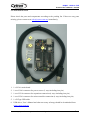
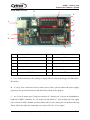
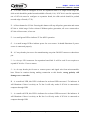
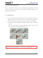
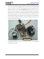
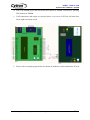
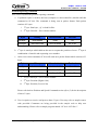
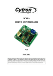
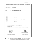
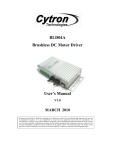
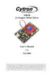
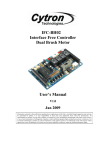
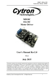
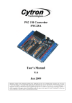
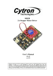
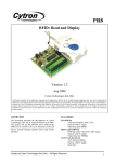
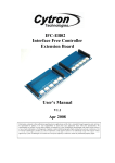
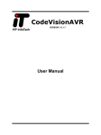
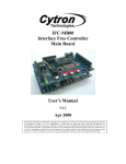
SC16A
SERVO CONTROLLER
User’s Manual
V2.0
September 2008
Information contained in this publication regarding device applications and the like is intended through suggestion only and may
be superseded by updates. It is your responsibility to ensure that your application meets with your specifications. No
representation or warranty is given and no liability is assumed by Cytron Technologies Incorporated with respect to the accuracy
or use of such information, or infringement of patents or other intellectual property rights arising from such use or otherwise. Use
of Cytron Technologies’s products as critical components in life support systems is not authorized except with express written
approval by Cytron Technologies. No licenses are conveyed, implicitly or otherwise, under any intellectual property rights.
Index
1. Introduction and Overview
1
2. Packaging List
2
3. How RC Servo Motor Works
3
4. Board Layout
5
5. Installation (hardware)
7
5.1
Setting Up SC16A
7
5.2
Connecting SC16A to Computer
10
5.3
Connecting SC16A to Microcontroller
12
5.4
Expanding SC16A for 32 Channels
14
6. Installation (software)
16
6.1
Sample Program for Computer
16
6.2
Sample Program for PIC16F877A
20
7. Getting Started
21
7.1 Using SC16A with Computer
21
7.2 Using SC16A with Microcontroller
21
7.3
23
Protocol for SC16A
8. Warranty (6 months)
Created by Cytron Technologies Sdn. Bhd. – All Right Reserved
25
ROBOT . HEAD to TOE
Product User’s Manual – SC16A
1. INTRODUCTION AND OVERVIEW
SC16A offers reliable yet user friendly RC Servo motor controller to hobbyist and students. It
is designed to control 16 independent standard RC (Remote Control) servo motors
simultaneously in a single board. Each servo signal pin is able to generate servo pulses from
0.5 ms to 2.5 ms, which is greater than the range of most servos, further allows for servos to
operate 180 degrees. Through serial communication, SC16A can be daisy chain in 2 boards to
offer independent control over 32 RC servo motors simultaneously. The host of SC16A can
either be a PC desktop, Laptop with USB port, or microcontroller with UART interface. Both
USB and UART interface present a flexible, fast and easy to use feature. With USB, it is plug
and play, user is able to get it running within 5 minutes time.
It is designed with capabilities and features of:
•
•
•
•
•
•
•
•
16 channels: Servo driven independently
Extendable to 32 Channels: Two controller linked together to drive 32 servos
Optional Position Reporting: User may request position of an individual servo.
Optional Servo Ramping: Choose one of 63 ramp rate (speed rate) for each servo.
Sample GUI for computer*: User may control the servo via sample GUI software.
Resolution: 1.367us.
UART: 9600 baud rate
Servo pulse: 0.5ms to 2.5ms.
* The sample GUI is provided free, therefore no further support is provided. It have been tested on Window XP Home, XP
Professional and Vista Starter.
This document explains the method to use SC16A.
Created by Cytron Technologies Sdn. Bhd. – All Rights Reserved
1
ROBOT . HEAD to TOE
Product User’s Manual – SC16A
2. PACKAGING LIST
Please check the parts and components according to the packing list. If there are any parts
missing, please contact us at [email protected] immediately.
2
3
1
4
5
1. 1 x SC16A main board
2. 1 set of 3961 connector for power source (2 ways including iron pin)
3. 1 set of 2510 connector for expansion connection (4 ways including iron pin)
4. 1 set of 2561 connector for microcontroller connection (4 ways including iron pin)
5. 1 x B Type USB cable
6. USB driver, User’s Manual and other necessary softcopy should be downloaded from
www.cytron.com.my
Created by Cytron Technologies Sdn. Bhd. – All Rights Reserved
2
ROBOT . HEAD to TOE
Product User’s Manual – SC16A
3. How RC Servo Motor works
Radio Control (RC) hobby servos are small actuators designed for remotely operating model
vehicles such as cars, airplanes, and boats. Nowadays, servos are become more popular in
robotics, creating humanoid robot, biologically inspired robot, robotic arm and etc. This is
because its’ ability to rotate and maintain and certain location, position or angle according to
control pulses from a single wire. Inside a typical servo contains a small motor and gearbox
to do the work, a potentiometer to measure the position of the output gear, and an electronic
circuit that controls the motor to make the output gear move to the desired position. Because
all of these components are packaged into a compact, low-cost unit, servos are great actuators
for robots.
Besides signal wire, a RC servo has other two leads: power and ground. The control signal is
a continuous stream of pulses that are 1 to 2 milliseconds long, repeated approximately fifty
times per second, as shown below.
The width of the pulses determines the position to which the servo moves. The servo moves
to its neutral, or middle, position when the signal pulse width is 1.5 ms. As the pulse gets
wider, the servo turns one way; if the pulse gets shorter, the servo moves the other way.
Typically, a servo will move approximately 90 degrees for a 1 ms change in pulse width.
However, the exact correspondence between pulse width and servo varies from one servo
manufacturer to another.
Created by Cytron Technologies Sdn. Bhd. – All Rights Reserved
3
ROBOT . HEAD to TOE
Product User’s Manual – SC16A
SC16A is designed to simultaneously generate 16 independent servo control signals. The
servo controller can generate pulses from 0.5 ms to 2.5 ms, which is greater than the range of
most servos, and which allows for a servo operating range of over 180 degrees.
Created by Cytron Technologies Sdn. Bhd. – All Rights Reserved
4
ROBOT . HEAD to TOE
Product User’s Manual – SC16A
4. BOARD LAYOUT
B
C
D
E
A
F
G
L
H
K
I
J
Label
Function
Label
Function
A
B type USB port socket
G
Small Orange LED (servo power)
B
Servo motor power source connector
H
Manufacturing test point
C
Servo motor ports
I
Expansion link connector
D
SC16A selection slide switch
J
4 way header pin
E
SC16A Reset button
K
Small red LED
F
Small green LED (5V)
L
Small yellow LED
A - is for USB connection to PC desktop or laptop. Please connect the B type of USB cable to
this socket.
B – is 2 way 3961 connector for servo motor power source, please connect the power supply
properly to the provided connector and check the polarity before plug in.
C – are 16 servo motor ports. Each port consists of 3 header pin. 16 ports are distributed to
both side of dsPIC controller. S1 - S6 at the left side while S7 – S16 at right side. The signal
pin is closest to dsPIC (middle of board). Both sides of servo motor port are labeled at the top.
Please follow the label for connecting servo port to SC16A, ‘S’ for signal.
Created by Cytron Technologies Sdn. Bhd. – All Rights Reserved
5
ROBOT . HEAD to TOE
Product User’s Manual – SC16A
D – is a slide switch to configure SC16A for expansion mode. For single board usage, the
slide switch should be pushed towards middle of board (1-16). If SC16A is used in expansion,
one of SC16As must be configure to expansion board, the slide switch should be pushed
towards edge of board (17-32).
E – is Reset button for SC16A. Pressing this button will stop all pulses generation and return
SC16A to initial stage if after released. Without pulses generation, all servo connected to
SC16A will not rotate, is free run.
F – is a small green LED to indicate 5V for dsPIC operation.
G – is a small orange LED to indicate power for servo motor. It should illuminate if power
source is connected properly.
H – is 5 ways header pin reserve for manufacturing test point. DONOT connect or short these
pin.
I – is a 4 ways 2510 connector for expansion board link. It will be used if user requires to
expand SC16A for 32 servo motors.
J – is a 4 ways header pin for user to connect power and signal wire from microcontroller
host. Please be cautions during making connection to this header, wrong polarity will
damage servo controller.
K – is a small red LED, this LED is indicator for on board USB converter’s Tx indicator. It
will illuminate if there is activity on Tx line. It will only works if SC16A is connected to
computer through USB
L – is a small red LED, this LED is indicator for on board USB converter’s Rx indicator. It
will illuminate if there is activity on Rx line. It will only works if SC16A is connected to
computer through USB
Created by Cytron Technologies Sdn. Bhd. – All Rights Reserved
6
ROBOT . HEAD to TOE
Product User’s Manual – SC16A
5. INSTALLATION (HARDWARE)
SC16A is designed to control RC servo motor. Following steps will guide user in using
SC16A. The controller can either be a microcontroller with UART interface or PC
desktop/Laptop with USB port.
5.1 Setting up SC16A
a. Servos are typically powered by independent power source ranging from 4.8V to 9V
(standard is 4.8V to 6.0V). This power source is normally battery or adaptor. The
power source should be connected to 3961 connector as shown in following photo.
• Servo power indicator LED (orange) will light on if the power source is connected
correctly.
• The power source should be able to provide several ampere of current if many
servos are expected to have loading simultaneously.
Caution: Always ensure the Power source for servo is connected correctly before
servo motor is connected to SC16A, else all servo motor will be damaged.
Created by Cytron Technologies Sdn. Bhd. – All Rights Reserved
7
ROBOT . HEAD to TOE
Product User’s Manual – SC16A
b. User must ensure the power source is connected correctly before plug-in servo to
SC16A. Servo cable may be plugged to any servo port on SC16A. When connecting
servos, be careful because the servo header pins (connector) are not polarized and it is
possible to plug in a servo backwards. ENSURE the connection of servo is correct;
else the servo may be destroyed. The signal (usually white, orange or yellow) wire
should be closest to controller chip (farthest from the edge of the board), and the black
wire should be closest to the edge of the board. Some servo connectors have a
polarizing nub that indicates the signal lead; that notch should be on the pin farthest
from the edge of the PCB. The function of each pin is being label at the top of servo
motor port, please follow the label.
Servo signal pin
c. Do remember the label (S1 to S16) of each servo motor to ease the program
development in later stage.
Created by Cytron Technologies Sdn. Bhd. – All Rights Reserved
8
ROBOT . HEAD to TOE
Product User’s Manual – SC16A
d. For basic connection (16 servos maximum), please ensure the slide switch (SW) is
being pushed towards middle of SC16A (1-16).
Slide switch
e. SC16A needs its own power; it can either come from USB power or other
microcontroller board power. However, the standard power source is 5V for SC16A.
f. Following steps will further explain the hardware setup for PC desktop/Laptop,
Microcontroller and also expansion mode.
Created by Cytron Technologies Sdn. Bhd. – All Rights Reserved
9
ROBOT . HEAD to TOE
Product User’s Manual – SC16A
5.2
Connecting SC16A to Computer
One of the main concerns in controlling servo is the hard work needed to get start. However,
with SC16A, getting start is easy as 1 2 3. SC16A offer an USB to serial converter onboard to
enable USB Plug and Play function. No RS232 (serial port, DB9) is needed on PC
desktop/Laptop to test SC16A. This will save tremendous work and time. Simply plug
SC16A to USB port of computer (PC or Laptop), install driver (1st time user only) and there
is an extra virtual COM port. After installation of GUI for SC16A (provided free), user can
start playing with servo motor in no time. Only power source for servo motor is needed if
SC16A is connected to PC. Anyway, the power of USB is isolated from the 5V pin (external
supply). In other words, USB power is not able to supply power for microcontroller
board.
a. Simply connect USB cable (B type) to SC16A USB socket as shown in following figure,
another end (A type) to PC desktop/Laptop.
USB
Created by Cytron Technologies Sdn. Bhd. – All Rights Reserved
Power source for
Servos
10
ROBOT . HEAD to TOE
Product User’s Manual – SC16A
b. Please refer to document named “USB Driver Installation Guide” for USB to UART
driver installation. USB driver needed can be downloaded from SC16A product page at
www.cytron.com.my
c. After plug in SC16A’s USB cable to computer and installation of driver, user is ready to
control servo motor from computer.
d. Please beware that, only one host can be connected to SC16A at a moment. Either
computer or a microcontroller. DONOT connect two hosts (computer and microcontroller)
to a SC16A at the same time.
Caution: Only one host should be connected to SC16A, either computer (through
USB cable) or microcontroller (through UART).
Created by Cytron Technologies Sdn. Bhd. – All Rights Reserved
11
ROBOT . HEAD to TOE
Product User’s Manual – SC16A
5.3
Connecting SC16A to Microcontroller
Another concern of user is for embedded system to control servo motors. For microcontroller
to interface with SC16A, the minimum requirement will be TTL UART (Universal
Asynchronous Receiver and Transmitter) and 5V supply. 5V will not be an issue since most
of embedded or microcontroller system is 5V powered, tapping the 5V from host system will
be reasonably easy. As for UART, a minimum of Transmit pin is required to send command
to SC16A.
a. Please refer to the sample schematic to interface SC16A to microcontroller. Following
sample schematic shows PIC16F877A interface to SC16A. No restriction to what type or
brand of microcontroller can be used, as long as it has UART peripheral.
b. Although SC16A come with Tx pin, it is an alternative for user to connect if positioning
report is needed. Thus minimum wires from the host, microcontroller to SC16A are 3
wires. Please use proper connector to connect the wires. Following figure show an
example of wire interface to SC16A. It uses 4 ways 2561 socket. Please ensure the cable
Created by Cytron Technologies Sdn. Bhd. – All Rights Reserved
12
ROBOT . HEAD to TOE
Product User’s Manual – SC16A
is not connected in wrong direction, wrong connection will spoilt SC16A and worst
the host or microcontroller.
Microcontroller
with 5V
c. In this setup, SC16A will share 5V power source from host or microcontroller board. If
5V power source is ON and connection is correct, the small green LED (5V) will light
ON to indicate controller is powered.
d. The hardware interface for SC16A to microcontroller host is ready. However in order to
control servo from microcontroller, user is require to write program for microcontroller
sending command according to protocol in software section.
Created by Cytron Technologies Sdn. Bhd. – All Rights Reserved
13
ROBOT . HEAD to TOE
Product User’s Manual – SC16A
5.4
Expanding SC16A for 32 Channels
SC16A provides the flexibility to be expanded and control 32 channels of servo motor
simultaneously. In some application, more than 16 servos are required. No worries, 2 units of
SC16A can be combined for expansion mode to control 32 servos. Following steps will guide
user to setup SC16A for expansion mode.
a. Two units of SC16A are needed.
b. Setup both SC16A according to steps in section 5.1. User may share the same power
source for servo motor. However, please ensure power source is capable to supply
higher current since more servos are used.
c. Create a back to back 4 ways cable for interlink between two SC16As. Following
figure shows the cable connection. Please ensure the polarity is correct.
Created by Cytron Technologies Sdn. Bhd. – All Rights Reserved
14
ROBOT . HEAD to TOE
Product User’s Manual – SC16A
d. Link up both SC16A with the cable. Following figure shows the sample connection.
Please ensure the 2510 connector is being connected, DONOT connect to header
pin, the header pin is only use for connection to host, microcontroller.
SC16A 2
SC16A 1
e. The slide switch “SW” for SC16A_1 (board 1) should be pushed towards inside board
(1-16), while for SC16A_2 (board 2) should be pushed towards outside board (17-32).
f. For SC16A_2, servo connected at “S1” will be recognized as “S17” in software. This
applied to the rest of servo port on SC16A_2. Every label should be added with 16
during software development.
Created by Cytron Technologies Sdn. Bhd. – All Rights Reserved
15
ROBOT . HEAD to TOE
Product User’s Manual – SC16A
6. INSTALLATION (SOFTWARE)
There are 2 software options for SC16A. The simplest way is to use the sample GUI program
provided by Cytron Technologies which need to be installed on computer, while another
program is the sample program for PIC16F877A to control servo through SC16A.
6.1 Sample Program for Computer
To ease user in using SC16A, Cytron Technologies has developed a GUI (Servo Control
Panel) for user to control SC16A from USB port. Following steps will guide user to install
Servo Control Panel and use it.
g. Extract the zipped file named “Servo Control Panel.zip”. This file can be downloaded
from Cytron website (www.cytron.com.my).
h. Double click on “setup.exe” to install the GUI.
i. A shortcut will be created at Window’s start up menu. To activate the GUI, go to start
-> All Programs -> Cytron Technologies -> Servo32Ch.
j. Before any setup at Servo32Ch can be done, please ensure hardware installation of
SC16A is being setup correctly, USB cable and power to servo motor is connected.
Besides, USB driver is a must to be installed.
k. After Servo Control Panel is activated, a window will pop out, following figure show
the window.
Created by Cytron Technologies Sdn. Bhd. – All Rights Reserved
16
ROBOT . HEAD to TOE
Product User’s Manual – SC16A
l. Ensure the USB is connected to computer, click the “Refresh” icon. Choose the COM
Ports by clicking the side bar, choose the last COM port. Normally, the extra virtual
COM port will be the largest number port after driver installation. Click on it.
m. Click the “Connect” icon and Servo Control Panel will show “COMXX connected”
n. Now, Servo Control Panel is ready to control the servo motor on SC16A, please
ensure the power for servo motor is connected properly.
Created by Cytron Technologies Sdn. Bhd. – All Rights Reserved
17
ROBOT . HEAD to TOE
Product User’s Manual – SC16A
o. User may drag the corresponding sliding bar to control particular servo motor. The
value at the bottom of each slide bar is position value where user may copy to
microcontroller host after finalizing the servo position at computer. This help user to
save more time and shorten the development time.
Control Slide Bar
Servo Position Value
Speed
p. Furthermore, user may set the speed at the bottom of position value at each slide bar.
The default value for speed is “0” which represent fastest speed. For further details of
speed, please refer section 7.3.
q. Please take note that position reporting is not implemented of Servo Control Panel.
Created by Cytron Technologies Sdn. Bhd. – All Rights Reserved
18
ROBOT . HEAD to TOE
Product User’s Manual – SC16A
r. For expanded mode where more than 16 servo motors are required, please setup
SC16A according to 5.4. Please use 16Ch to control servo motor on SC16A_1 board,
while 32Ch to control servo motor on SC16A_2 board.
s. Right bottom corner offer a “Reset” icon which provide fast reset to all servo motors
to the center position.
Created by Cytron Technologies Sdn. Bhd. – All Rights Reserved
19
ROBOT . HEAD to TOE
Product User’s Manual – SC16A
6.2 Sample program for PIC16F877A
Most servo motor is being used as actuator for humanoid, legged mobile robot and many
other applications. All these developments are based on embedded controller, which is
microcontroller or microprocessor. Considering this reason, Cytron Technologies has also
developed two samples embedded program using PICC Lite for PIC16F877A. Following
steps will guide user to use the sample program.
a. The 1st sample program (SC16A+16F.zip) can be downloaded from Cytron website
(www.cytron.com.my), the link under SC16A page.
b. Extract the file into hard disc.
c. Ensure the hardware interface for microcontroller to SC16A is setup properly. Besides,
the power for servo motor is also needed. Please refer to section 5.3 for example of
schematic.
d. There are 2 files available for user, SC16A+16F.c and SC16A+16F.hex. For fast
testing, user may load SC16A+16F.hex to PIC16F877A and plug into microcontroller
board that was being completed in step c.
e. The sample program is based on SK40B startup kit. Power up the board, it will further
power the SC16A. Press and release RESET button on SK40B, followed by pressing
SW1 button.
f. If all connections and setups are correctly done, every servo on SC16A will turn from
left to right and return to left.
g. Please refer to SC16A+16F.c for details on method to send command to SC16A.
h. The 2nd sample program (SC16A+16F+Pos.zip) can be downloaded from Cytron
website (www.cytron.com.my), the link under SC16A page.
i. This sample program shows the sample of using positioning report to control
particular servo motor.
j. Please follow step from b to f.
k. Sample source code for PIC16F877A is compatible for PIC16F876A. Cytron
Technologies developed based on PIC16F877A is because PICC Lite does not
support PIC16F876A.
Created by Cytron Technologies Sdn. Bhd. – All Rights Reserved
20
ROBOT . HEAD to TOE
Product User’s Manual – SC16A
7. GETTING STARTED
7.1
Using SC16A with Computer
After installation of sample GUI and USB driver, user is ready to use SC16A with computer.
Setup SC16A according to steps in 5.1. Plug USB B-type connector to SC16A and the other
end to computer’s USB port. Double click on the sample GUI icon to open a window shown.
Following steps guide user to control servo from computer.
a. Before the GUI is able to control servos on SC16A, connection must be made. Click
on COM port, choose the last COM port, click connect. Please follow the steps under
section 6.1
b. Once the status shows connected. User is free to drag the bar of each servo label. If
every setup is correct, corresponding servo will rotate accordingly. User may record
the decimal value for particular angle or position of servo. This feature help to save
development time, especially during gates setting, body or arm moving sequence.
Please do utilize this GUI.
7.2
Using SC16A with Microcontroller
More work will be needed if microcontroller is used as host of SC16A. This section will
show sample of using SK40B + PIC16F877A as host of SC16A.
a. Setup up SK40B with PIC16F877A. Load the sample program using UIC00A or any
other programmer.
b. Setup SC16A according to steps in section 5.1.
c. Connect Vcc(5V), Gnd(0V) and RC6/Tx (pin 25) to SC16A respectively.
i. (SK40B) RC6 to RX (SC16A)
ii. (SK40B) RC7 to TX (SC16A) – optional, if position report is needed.
iii. (SK40B) Vss to GND (SC16A)
iv. (SK40B) 5V to 5V (SC16A)
Created by Cytron Technologies Sdn. Bhd. – All Rights Reserved
21
ROBOT . HEAD to TOE
Product User’s Manual – SC16A
d. Power up SK40B, press and release RESET button of SK40B. Followed by pressing
SW1 button on SK40B.
e. If all connections and setups are correctly done, every servo on SC16A will turn from
left to right and return to left.
f. Please refer to sample program files for details of method to send command to SC16A.
Created by Cytron Technologies Sdn. Bhd. – All Rights Reserved
22
ROBOT . HEAD to TOE
Product User’s Manual – SC16A
7.3 Protocol of SC16A
There are two protocols for SC16A. The 1st protocol is important which is uses to send
command to SC16A, further control a particular servo to a position with a defined speed. 2nd
protocol is for host to request the current position of servo.
Of course, the 2nd protocol is alternative to user, if position reporting is not a requirement, it
can be ignored. If position reporting is required, please do remember to connect the Tx pin of
SC16A to Rx pin of host.
Position and Speed Command
Both computer and microcontroller actually send command to SC16A serially. This section
explains the protocol to send command.
a. The command is being sent in packet format. Each packet consists of 4 bytes.
i. 1st byte: Start byte + Servo motor number
ii. 2nd byte: Position (Higher 6 bit)
iii. 3rd byte: Position (Lower 6 bit)
iv. 4th byte: Speed
b. A packet of 4 bytes must be sent in order to control each servo. Thus to control 16
servos in an instant, a total of 64 bytes must be sent.
c. SC16A is being setup to disable every servo on start up. Not pulses will be generated
upon power up or reset. Pulses will only be generated for particular servo port if
corresponding command is received by SC16A.
Created by Cytron Technologies Sdn. Bhd. – All Rights Reserved
23
ROBOT . HEAD to TOE
Product User’s Manual – SC16A
d. SC16A translate four bytes of data into three parameter:
Byte
Binary
Hexadecimal
Decimal
1st Byte
0b01XXXXXX
0x41 to 0x60
65 to 96
2nd Byte
0b00XXXXXX
0x00 to 0x3F
0 to 63
3rd Byte
0b00XXXXXX
0x00 to 0x3F
0 to 63
4th Byte
0b00XXXXXX
0x00 to 0x3F
0 to 63
i. 1st byte is combination of start bit and servo number.
7
6
5
4
3
2
1
0
0
1
X
X
X
X
X
X
Start bit
Servo number (1-32)
ii. 2nd and 3rd byte combined to provide 12 bit data of servo position.
2nd byte: Higher 6 bit
3rd byte: Lower 6 bit
7
6
5
4
3
2
1
0
7
6
5
4
3
2
1
0
0
0
X
X
X
X
X
X
0
0
X
X
X
X
X
X
11 10
9
8
7
6
5
4
3
2
1
0
X
X
X
X
X
X
X
X
X
X
X
X
12 bit of servo position
iii. 4th byte represents the speed of servo rotation.
7
6
5
4
3
2
1
0
0
0
X
X
X
X
X
X
Created by Cytron Technologies Sdn. Bhd. – All Rights Reserved
24
ROBOT . HEAD to TOE
Product User’s Manual – SC16A
e. The 1st byte is combination of start bit and servo number. 6th bit must be “1” to
indicate this byte is 1st byte of SC16A command.
f. 2nd and 3rd byte will be combined to form a 12 bit Servo Position; 0-1463. The
resolution of SC16A is 1.367us. It will start from 0.5ms and increase the duty cycle of
pulses according to value of Position. Thus, following formula show the duty cycle of
pulses generated:
Duty cycle = (resolution x Servo Position) + 0.5ms
= (1.367us x Servo Position) + 0.5ms
g. 4th byte determines the speed of servo rotation for each servo independently. The
higher value, the faster servo will rotate to its Position. However, value of ‘0’ will
disable the speed, thus provide normal speed, the servo motor will rotate according to
it own maximum speed. 63 ramp rates allow the user to set the speed of each servo.
Decimal value ‘1’ indicates that the servo will run at slowest speed and decimal value
‘63’ will run at fastest speed. At each 20ms interval, the current servo position will
increase or decrease with the speed value depending on whether the position is greater
or lesser than the new position.
The speed of servo motor is depending on the brand of servo motors. Therefore,
different type of servo would result in different speed. For Cytron C36S servo, the
approximate time of speed range from 0 degree to 180 degree of rotation is shown as
follows:
0 = 0.3 seconds
40 = 3.60 seconds
1 = 2.0 minutes
50 = 2.80 seconds
10 = 14 seconds
60 = 2.2 seconds
20 = 7.0 seconds
63 = 1.9 seconds
30 = 4.14 seconds
h. For more details, user may refer to sample source code provided. Comments are being
provided in the sample code to help user understanding.
Created by Cytron Technologies Sdn. Bhd. – All Rights Reserved
25
ROBOT . HEAD to TOE
Product User’s Manual – SC16A
Position Reporting Command
This section explains the position reporting command.
a. If position report is needed, the host (computer or microcontroller) should send this
command to SC16A. The command is being sent in packet format. Each packet
consists of 2 bytes.
i. 1st byte: Start byte, ‘@’ or 0x40 in Hex.
ii. 2nd byte: Start bit + Servo motor number.
Byte
Binary
Hexadecimal
Decimal
1st Byte
0b0100000
0x40
64
2nd Byte
0b01XXXXXX
0x41 to 0x60
65 to 96
b. 1st byte is start byte which indicate the user to request the position of servo. 2nd byte is
combination of start bit and requesting servo number.
c. After receive this command, SC16A will send out a packet format which consists of 3
bytes.
Byte
Binary
Hexadecimal
Decimal
1st Byte
0b01XXXXXX
0x41 to 0x60
65 to 96
2nd Byte
0b00XXXXXX
0x00 to 0x3F
0 to 63
3rd Byte
0b00XXXXXX
0x00 to 0x3F
0 to 63
i. 1st bye: Start byte + Servo motor number
ii. 2nd byte: Position (Higher 6 bit)
iii. 3rd byte: Position (Lower 6 bit)
Please refer back to Position and Speed Command section (d) to (f) for the description
of these 3 bytes.
d. User is requires to receive and process these 3 bytes. User may refer to sample source
code provided. Comments are being provided in the sample code to help user
understanding. Please refer to sample program named “SC16A+16F+Pos.c”.
Created by Cytron Technologies Sdn. Bhd. – All Rights Reserved
26
ROBOT . HEAD to TOE
Product User’s Manual – SC16A
8. WARRANTY
¾ Product warranty is valid for 6 months.
¾ Warranty only applies to manufacturing defect.
¾ Damage caused by misuse is not covered under warranty.
¾ Warranty does not cover freight cost for both ways.
Prepared by
Cytron Technologies Sdn. Bhd.
19, Jalan Kebudayaan 1A,
Taman Universiti,
81300 Skudai,
Johor, Malaysia.
Tel:
Fax:
+607-521 3178
+607-521 1861
URL: www.cytron.com.my
Email: [email protected]
[email protected]
Created by Cytron Technologies Sdn. Bhd. – All Rights Reserved
27