1
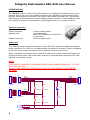
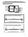
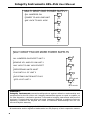
Integrity Instruments 485-PLG User Manual
Integrity
Instruments
P.O. Box 451
Pine River Minnesota
56474 USA
Order Phone
Fax Phone
Tech Phone
800-450-2001
218-587-3414
218-587-3120
http://www.integrityusa.com
485-PLG
For
485 Converters
and
485 Peripherals
1
Integrity Instruments 485–PLG User Manual
INTRODUCTION
The 485-PLG mates to our line of rs-485 products. It is designed to attach directly to the
terminal strip of the unit via the header connector pins. RS-485 connections and power
are then made by plug connectors to all units on the rs-485 multi drop link. This reduces
field wiring time and makes any field de-bugging simple and easy. Future additional units
can easily be inserted into the system by just plugging them in, no messy re-wiring.
Physical properties
Power connector
Modular plug
2.5mm center positive
6-4 modular plug
amp/TYCO electronics 5-641335-3
or equivalent.
.025 inch square pins
Header connector
Schematic
The drawing below shows the schematic for the 485-PLG. Power is supplied through the
power connector J4. A LED on the board shows the presence of power. Power is supplied
to the unit, and is routed via jumpers to the modular connectors J1 and J2.
When connections are made from J1 and J2 to other units, power and rs-485 signals are
supplied to those units. The rs-485 daisy chaining is accomplished simple and fast, making field connections a snap.
NOTE:
PLUG USES STANDARD 6-4 CONNECTORS. PLUG CONNECTIONS PIN 1 TO PIN 1,
PIN 2 TO PIN 2 ETC.
DO NOT USE PREMADE TELEPHONE CORD AS THE CONNECTIONS ARE REVERSED.
J1
1
2
3
4
5
6
6 PIN RJ11
J2
1
2
3
4
5
6
J3
J1
SIG A
SIG B
GND
V+
1
2
3
4
SIG A
SIG B
GND
V+
4 PIN RJ11
JP1
D1
LED
1
2
3
4
SIG A
SIG B
GND
V+
4 PIN RJ11
J4
3
2
1
V+
GND
POWER JACK 2.5MM
JUMPER
JUMPER
JP3
JP4
JUMPER
JUMPER
1
2
3
4
5
5 PIN HEADER
JP2
J2
SIG A
SIG B
GND
V+
6 PIN RJ11
2
SIG A
SIG B
SHIELD
GND
V+
R1
1.2K
Integrity Instruments 485-PLG User Manual
Physical Positions and Connections
4
J-2
5
J-1
SIG A
SIG B
GND
V+
JP3
JP1
JP2
JP4
J3
SIG A
SIG B
GND
V+
SIG A
SIG B
3
2
J-4
1
SHLD
GND
V+
PWR
POINT TO POINT TWO POWER SUPPLYS
BOTH
PWR
ANY ONE
J1
J2
J2
J1
PWR
ALL JUMPERS REMOVED BOTH PLUGS
BOTH
POINT TO POINT ONE POWER SUPPLY
EITHER
PWR
ANY ONE
J1
J2
J2
J1
PWR
ALL JUMPERS REMAIN BOTH PLUGS
EITHER
3
Integrity Instruments 485–PLG User Manual
MULTI DROP ONE POWER SUPPLY
ALL JUMPERS ON
ANY JACK TO ANY JACK
PWR
POWER TO ANY ONE UNIT
J1
J2
ANY
J1
J2
PWR
ANY
J1
J2
PWR
ANY
J1
J2
PWR
ANY
MULTI DROP TWO OR MORE POWER SUPPLYS
REMOVE JP1 AND JP2 ON UNIT 3
J1
J2
PWR
ALL JUMPERS ON EXCEPT UNIT 3
1
ANY
J1
PRECEEDING UNITS MUST
PLUG INTO J1 OF UNIT 3
INTO J2 OF UNIT 3
2
ANY
J1
J2
PWR
SUCCEDING UNITS MUST PLUG
J2
PWR
ANY JACK TO ANY JACK EXCEPT
3
ANY
FOR UNIT 3 AND LOWER
J1
J2
PWR
4
ANY
FOR UNIT 3 AND LOWER
WARRANTY
Integrity Instruments warranties all products against defective workmanship and
components for the life of the unit. Integrity Instruments agrees to repair or replace, at
it’s sole discretion, a defective product if returned to Integrity Instruments with proof of
purchase. Products that have been mis-used, improperly applied, or subject to adverse
operating conditions fall beyond the realm of defective workmanship and are not
convered by this warranty.
Copyright © 2000-2002, Integrity Instruments
All trademarks and/or registered trademarks are the property of their respective owners.
4