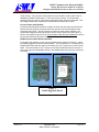
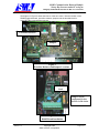
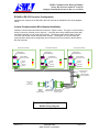
1
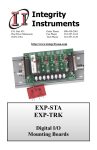
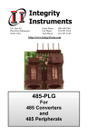
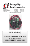
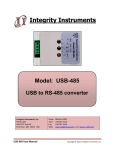
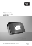
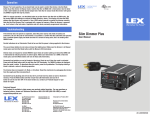
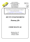
RS485 Communication Between
Sunny Boy Inverters
and a PC using an Integrity
Instruments RS-485 to RS-232
Converter
Technical Note
Revision 1.1
August 30, 2004
Revision History
1.0
1.1
1.2
August 6, 2003
August 14, 2003
August 30, 2004
Richard Scott
Richard Scott
Kent Sheldon
Original Release
Document Cleanup
Sunny Buddy update
SMA America, Incorporated
12438 Loma Rica Dr. Suite C
Grass Valley, CA 95945
530.273.4895
RS485 Communication Between Multiple
Sunny Boy Inverters and a PC using an
Integrity Instruments RS-485 to RS-232 converter
Table of Contents
Table of Contents................................................................................................................ 2
Overview............................................................................................................................. 3
Safety Warning ................................................................................................................... 3
Application.......................................................................................................................... 3
Necessary Accessory Equipment........................................................................................ 3
Cabling Requirements......................................................................................................... 3
Hardware Installation and Configuration............................................................................ 3
Inverter Resistor Removal .............................................................................................. 3
Inverter Jumper Configuration........................................................................................ 4
RS485 Communication Board Installation ..................................................................... 4
RS-485 to RS-232 Converter Configuration....................................................................... 6
Inverter Communication Wire Harness Installation ........................................................... 6
Troubleshooting RS485 Communication ........................................................................... 7
Revision 1.2
Copyright 2004
SMA America, Incorporated
Page 2 of 7
RS485 Communication Between Multiple
Sunny Boy Inverters and a PC using an
Integrity Instruments RS-485 to RS-232 converter
Overview
This technical note details how to set up RS-485 communication between one or more Sunny
Boy photovoltaic inverters (SB) and a PC using a RS485 to RS-232 converter. This document
does not attempt to describe the configuration of the Sunny Data software, used to communicate
between the PC and the inverters (refer to the Sunny Data Software Users Manual for further
information).
Safety Warning
The inverter operates with potentially lethal voltage and current from multiple power sources.
Only qualified personnel should attempt to work on the inverter.
The inverter must be isolated and locked-out from all AC and DC power sources prior to installing
the hardware necessary for RS485 communication. Allow a minimum of five minutes for internal
capacitors to discharge before removing the cover of the inverter.
Application
Communication between one or more inverter(s) and PC may be accomplished using an RS485
direct drop-net wire connection. The maximum wire run distance between the converter and the
farthest inverter is 1200 meters (4000 feet).
Note: The wiring diagram now includes information on connection to a Palm serial device. For
information on interfacing directly to a Sunny Boy inverter from a Palm device, please contact
Sunny Buddy (contact information may be found in the appendix).
Necessary Accessory Equipment
The following is a list of accessory equipment required:
-Integrity Instruments model 485-25E RS-485 to RS-232 converter.
-Integrity Instruments model PS9CST Power Supply.
-RS485 communication boards (one per SB inverter).
-RS485 wire harness between each inverter.
-RS485 wire harness between converter and one inverter.
-Sunny Data PC software (Free download from the www.sma-america.com website).
-PC running Win95 or greater, with an RS232 communication port.
Cabling Requirements
If you choose to construct your own cable, we recommend using the following wire type:
- #24 AWG, stranded copper conductors
- Two twisted-pair (four wires) with overall shield (foil or braid), with drain wire
- Low capacitance, less than 15pF per foot.
- Outer insulation suitable for the specific application (outdoor, wire tray, UV resistant,
wet weather, etc.)
Inverter Hardware Installation and Configuration
The following hardware changes must be made to each Sunny Boy inverter for RS485
communication:
Inverter Resistor Removal (Some newer units may not have these)
Disconnect the inverter from AC and DC power sources. Wait 5 minutes before removing
the cover to let the internal capacitors discharge.
Remove the cover of the Sunny Boy inverter.
There are two resistors (light-blue or tan) in the lower left region of the small control
board in the center of the inverter enclosure (these are shown in the diagram at the end
Revision 1.2
Copyright 2004
SMA America, Incorporated
Page 3 of 7
RS485 Communication Between Multiple
Sunny Boy Inverters and a PC using an
Integrity Instruments RS-485 to RS-232 converter
of this section). They are part of the powerline communication circuitry which must be
disabled for RS485 communication. These need to be removed. We recommend
carefully cutting one side of each resistor and bending them away from the board. This
will simplify reconnection if powerline communication is desired in the future.
Inverter Jumper Configuration
Located directly below the powerline resistors are three sets of jumper pins labeled S4.
Remove all three jumpers (if present) from each inverter in the communication chain,
except the last inverter. The last inverter must have the lower jumper installed. We
recommend hanging unused jumpers from one pin only for future use. (See Figure 3)
Refer to the diagram (Figure 4) in the Communication Wire Harness Installation section in
this document showing the jumper settings for all inverters in the chain.
RS485 Communication Board Installation
To the left of the resistors are two, two-row header sockets (shown in Figure 2). Install
the RS485 piggyback board onto these headers. The long socket (2 x 7 sockets) on the
RS485 board mates with the upper set of header pins (2 x 7 pins) on the inverter control
board. The lower header row (2 x 6 pins) on the control board will have an extra set of
pins to the right side that do not connect to the RS485 board which has less sockets (2 x
5 sockets).
Figure 1
RS485 Piggyback Board
Revision 1.2
Copyright 2004
SMA America, Incorporated
Page 4 of 7
RS485 Communication Between Multiple
Sunny Boy Inverters and a PC using an
Integrity Instruments RS-485 to RS-232 converter
The diagram in Figure 2 shows the interior of the an inverter. Note the location of the
RS485 piggyback board, powerline resistors, jumpers and the terminal block for
connecting the communication harness.
Powerline Resistors
Jumpers
Figure 2
Powerline Resistors and Jumper Locations
Pins Not
Used
Jumpers shown
configured for last
inverter in the chain.
Figure 3
RS485 Board Installation
Revision 1.2
Copyright 2004
SMA America, Incorporated
Page 5 of 7
RS485 Communication Between Multiple
Sunny Boy Inverters and a PC using an
Integrity Instruments RS-485 to RS-232 converter
RS-485 to RS-232 Converter Configuration
Install the two Jumpers on the RS-485 to RS-232 converter as indicated on the wiring diagram
below.
Inverter Communication Wire Harness Installation
Install the communication wire harness as shown in Figure 4 below. This type of communication
wiring is commonly referred to as a ‘drop-net’. It is simply three daisy-chained serial wires with
termination resistors on both ends of the network. The jumpers within the RS-485 to RS-232
converter and the last Inverter activate these resistors. The diagram in Figure 4 shows the
communication harness wire configuration and connection from the inverters to the RS-485 to
RS-232 converter:
Sunny Boy Main Control Board
RS485 Piggyback
Communication Board
S4
1 2 3 4 5 6 7 8 910
RS485 Piggyback
Communication Board
RS485 Piggyback
Communication Board
Powerline Resistors
Removed (Cut and Lift)
485PB-G3
Sunny Boy Main Control Board
Sunny Boy Main Control Board
Powerline Resistors
Removed (Cut and Lift)
485PB-G3
Open Pins
Not Used
S4
Lower Pins
Jumpered
1 2 3 4 5 6 7 8 910
Powerline Resistors
Removed (Cut and Lift)
485PB-G3
Open Pins
Not Used
Open Pins
Not Used
S4
Jumper Pins
Not Mounted
Jumper Pins
Not Mounted
1 2 3 4 5 6 7 8 910
Connect Shield to Each
Inverter Chassis
5
8
3
Connect to Palm
Serial
Hot-Sync Cradle
DB9-Female to SBC
Sunny Boy (COM1) Port
A
B
Shld
Gnd
+V
7.5-24VDC
250mA
Jumpers Installed
DB9 Male to
DB9 Male
Null Modem Adapter
DB9 Female to
DB25 Male Adapter
Integrity Instruments
Model 485-25E RS-485
to RS-232 Converter
Figure 4
RS485 Wiring Diagram
Revision 1.2
Copyright 2004
SMA America, Incorporated
Page 6 of 7
RS485 Communication Between Multiple
Sunny Boy Inverters and a PC using an
Integrity Instruments RS-485 to RS-232 converter
Troubleshooting RS485 Communication
Most problems installing RS485 are caused by improper wiring or incorrect use of the
configuration jumpers. We recommend using wire that is clearly color coded to simplify
installation and to help maintain continuity throughout the communication circuit. Some additional
troubleshooting points to consider:
- Make sure all of the powerline resistors have been removed from the SB inverter
control boards.
- Verify the jumpers have been configured properly in the SB inverters. Remember,
the jumpers for the last inverter in the drop-net chain are set differently than the rest.
- Verify the RS485 boards are properly installed within each SB inverter.
- Verify that wires are not broken in insulation if using solid strand wire.
- Verify the jumper settings are set properly for on the RS-485 to RS-232 converter
device. (two jumpers should be installed)
- Verify that converter is powered up. (yellow LED lit)
- If the length of cable is greater than 200 feet verify that shielded cable is used.
- Verify that Sunny Data and NOT Sunny Data Control is being used for
communication between PC and inverters.
(Sunny Data Control is only used with Sunny Boy Control units)
Contact Information
SMA America, Inc.
12438-C Loma Rica Dr.
Grass Valley, CA 95945
Phone: 530-273-4895
Fax: 530-274-7271
www.sma-america.com
Integrity Instruments, Inc.
P.O. Box 451
2642 20th Ave. SW
Pine River, MN 56474
Order Phone: 800-450-2001
Fax Phone: 218-587-3414
Tech Phone: 218-587-3120
http://www.integrityusa.com
Sunny Buddy:
John Powers
[email protected]
www.poohbah.com
Revision 1.2
Copyright 2004
SMA America, Incorporated
Page 7 of 7