1
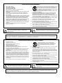
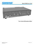
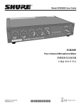
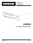
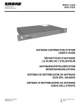
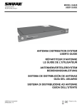
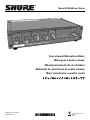
Model SCM268 User Guide MASTER 1 2 AUX IN 4 3 VE OUTPUT LE -20 icrop SCM268 m hone mixe -10 0 LMETER +6 +12 +18 POW ER r Four-channel Microphone Mixer Mélangeur à quatre canaux Mikrofonmischpult mit vier Kanälen Mezclador de micrófonos de cuatro canales Mixer microfonico a quattro canali 4 チャンネルマイクロホンミキサーです ©2008 Shure Incorporated 27D8646 (Rev. 6) Printed in U.S.A. ! IMPORTANT SAFETY INSTRUCTIONS ! 1. 2. 3. 4. 5. 6. 7. 8. 9. 10. 11. READ these instructions. KEEP these instructions. HEED all warnings. FOLLOW all instructions. DO NOT use this apparatus near water. CLEAN ONLY with dry cloth. DO NOT block any ventilation openings. Install in accordance with the manufacturer's instructions. DO NOT install near any heat sources such as radiators, heat registers, stoves, or other apparatus (including amplifiers) that produce heat. DO NOT defeat the safety purpose of the polarized or grounding-type plug. A polarized plug has two blades with one wider than the other. A grounding type plug has two blades and a third grounding prong. The wider blade or the third prong are provided for your safety. If the provided plug does not fit into your outlet, consult an electrician for replacement of the obsolete outlet. PROTECT the power cord from being walked on or pinched, particularly at plugs, convenience receptacles, and the point where they exit from the apparatus. ONLY USE attachments/accessories specified by the manufacturer. 12. USE only with a cart, stand, tripod, bracket, or table specified by the manufacturer, or sold with the apparatus. When a cart is used, use caution when moving the cart/apparatus combination to avoid injury from tip-over. 13. UNPLUG this apparatus during lightning storms or when unused for long periods of time. REFER all servicing to qualified service personnel. Servicing is required when the apparatus has been damaged in any way, such as power-supply cord or plug is damaged, liquid has been spilled or objects have fallen into the apparatus, the apparatus has been exposed to rain or moisture, does not operate normally, or has been dropped. DO NOT expose the apparatus to dripping and splashing. DO NOT put objects filled with liquids, such as vases, on the apparatus. The MAINS plug or an appliance coupler shall remain readily operable. The airborne noise of the apparatus does not exceed 70dB (A). Apparatus with CLASS I construction shall be connected to a MAINS socket outlet with a protective earthing connection. To reduce the risk of fire or electric shock, do not expose this apparatus to rain or moisture. Do not attempt to modify this product. Doing so could result in personal injury and/or product failure. 14. 15. 16. 17. 18. 19. 20. This symbol indicates that there are important operating and maintenance instructions in the literature accompanying this unit. This symbol indicates that dangerous voltage constituting a risk of electric shock is present within this unit. WARNING: Voltages in this equipment are hazardous to life. No user-serviceable parts inside. Refer all servicing to qualified service personnel. The safety certifications do not apply when the operating voltage is changed from the factory setting. ! CONSIGNES DE SÉCURITÉ IMPORTANTES ! 1. 2. 3. 4. 5. 6. 7. 8. 9. 10. 11. LIRE ces consignes. CONSERVER ces consignes. OBSERVER tous les avertissements. SUIVRE toutes les consignes. NE PAS utiliser cet appareil à proximité de l'eau. NETTOYER UNIQUEMENT avec un chiffon sec. NE PAS obstruer les ouvertures de ventilation. Installer en respectant les consignes du fabricant. Ne pas installer à proximité d'une source de chaleur telle qu'un radiateur, une bouche de chaleur, un poêle ou d'autres appareils (dont les amplificateurs) produisant de la chaleur. NE PAS détériorer la sécurité de la fiche polarisée ou de la fiche de terre. Une fiche polarisée comporte deux lames dont l'une est plus large que l'autre. Une fiche de terre comporte deux lames et une troisième broche de mise à la terre. La lame la plus large ou la troisième broche assure la sécurité de l'utilisateur. Si la fiche fournie ne s'adapte pas à la prise électrique, demander à un électricien de remplacer la prise hors normes. PROTÉGER le cordon d'alimentation afin que personne ne marche dessus et que rien ne le pince, en particulier au niveau des fiches, des prises de courant et du point de sortie de l'appareil. UTILISER UNIQUEMENT les accessoires spécifiés par le fabricant. 12. 13. 14. 15. 16. 17. 18. 19. 20. Ce symbole indique la présence d'une tension dangereuse dans l'appareil constituant un risque de choc électrique. UTILISER uniquement avec un chariot, un pied, un trépied, un support ou une table spécifié par le fabricant ou vendu avec l'appareil. Si un chariot est utilisé, déplacer l'ensemble chariot-appareil avec précaution afin de ne pas le renverser, ce qui pourrait entraîner des blessures. DÉBRANCHER l'appareil pendant les orages ou quand il ne sera pas utilisé pendant longtemps. CONFIER toute réparation à du personnel qualifié. Des réparations sont nécessaires si l'appareil est endommagé de quelque façon que ce soit, comme par exemple : cordon ou prise d'alimentation endommagé, liquide renversé ou objet tombé à l'intérieur de l'appareil, exposition de l'appareil à la pluie ou à l'humidité, appareil qui ne marche pas normalement ou que l'on a fait tomber. NE PAS exposer cet appareil aux égouttures et aux éclaboussements. NE PAS poser des objets contenant de l'eau, comme des vases, sur l'appareil. La prise SECTEUR ou un adaptateur d'alimentation doit toujours rester prêt(e) à être utilisé(e). Le bruit aérien de l'appareil ne dépasse pas 70 dB (A). L'appareil de construction de CLASSE I doit être raccordé à une prise SECTEUR dotée d'une protection par mise à la terre. Pour réduire les risques d'incendie ou de choc électrique, ne pas exposer cet appareil à la pluie ou à l'humidité. Ne pas essayer de modifier ce produit. Une telle opération est susceptible d'entraîner des blessures ou la défaillance du produit. Ce symbole indique que la documentation fournie avec l'appareil contient des instructions d'utilisation et d'entretien importantes. AVERTISSEMENT : Les tensions à l'intérieur de cet équipement peuvent être mortelles. Aucune pièce interne réparable par l'utilisateur. Confier toute réparation à du personnel qualifié. Les certifications de sécurité sont invalidées lorsque le réglage de tension d'usine est changé. ! WICHTIGE SICHERHEITSHINWEISE ! 1. 2. 3. 4. 5. 6. 7. 8. 9. 10. 11. Diese Hinweise LESEN. Diese Hinweise AUFHEBEN. Alle Warnhinweise BEACHTEN. Alle Anweisungen BEFOLGEN. Dieses Gerät NICHT in der Nähe von Wasser verwenden. NUR mit einem sauberen Tuch REINIGEN. KEINE Lüftungsöffnungen verdecken. Gemäß den Anweisungen des Herstellers einbauen. Nicht in der Nähe von Wärmequellen, wie Heizkörpern, Raumheizungen, Herden oder anderen Geräten (einschließlich Verstärkern) installieren, die Wärme erzeugen. Die Schutzfunktion des Schukosteckers NICHT umgehen. Bei Steckern für die USA gibt es polarisierte Stecker, bei denen ein Leiter breiter als der andere ist; US-Stecker mit Erdung verfügen über einen dritten Schutzleiter. Bei diesen Steckerausführungen dient der breitere Leiter bzw. der Schutzleiter Ihrer Sicherheit. Wenn der mitgelieferte Stecker nicht in die Steckdose passt, einen Elektriker mit dem Austauschen der veralteten Steckdose beauftragen. VERHINDERN, dass das Netzkabel gequetscht oder darauf getreten wird, insbesondere im Bereich der Stecker, Netzsteckdosen und an der Austrittsstelle vom Gerät. NUR das vom Hersteller angegebene Zubehör und entsprechende Zusatzgeräte verwenden. 12. NUR in Verbindung mit einem vom Hersteller angegebenen oder mit dem Gerät verkauften Transportwagen, Stand, Stativ, Träger oder Tisch verwenden. Wenn ein Transportwagen verwendet wird, beim Verschieben der Transportwagen-Geräte Einheit vorsichtig vorgehen, um Verletzungen durch Umkippen zu verhüten. 13. Das Netzkabel dieses Geräts während Gewittern oder bei längeren Stillstandszeiten aus der Steckdose ABZIEHEN. Alle Reparatur- und Wartungsarbeiten von qualifiziertem Kundendienstpersonal DURCHFÜHREN LASSEN. Kundendienst ist erforderlich, wenn das Gerät auf irgendwelche Weise beschädigt wurde, z.B. wenn das Netzkabel oder der Netzstecker beschädigt wurden, wenn Flüssigkeiten in das Gerät verschüttet wurden oder Fremdkörper hineinfielen, wenn das Gerät Regen oder Feuchtigkeit ausgesetzt war, nicht normal funktioniert oder fallen gelassen wurde. Dieses Gerät vor Tropf- und Spritzwasser SCHÜTZEN. KEINE mit Wasser gefüllten Gegenstände wie zum Beispiel Vasen auf das Gerät STELLEN. Der Netzstecker oder ein Gerätekuppler müssen leicht betriebsbereit bleiben. Der Luftschall des Geräts überschreitet 70 dB (A) nicht. Das Gerät mit Bauweise der KLASSE I muss mit einem Schukostecker mit Schutzleiter in eine Netzsteckdose mit Schutzleiter eingesteckt werden. Dieses Gerät darf nicht Regen oder Feuchtigkeit ausgesetzt werden, um das Risiko von Bränden oder Stromschlägen zu verringern. Nicht versuchen, dieses Produkt zu modifizieren. Ansonsten könnte es zu Verletzungen und/oder zum Produktausfall kommen. 14. 15. 16. 17. 18. 19. 20. Dieses Symbol zeigt an, dass gefährliche Spannungswerte, die ein Stromschlagrisiko darstellen, innerhalb dieses Geräts auftreten Dieses Symbol zeigt an, dass das diesem Gerät beiliegende Handbuch wichtige Betriebs- und Wartungsanweisungen enthält. ACHTUNG: Die in diesem Gerät auftretenden Spannungen sind lebensgefährlich. Das Gerät enthält keine Teile, die vom Benutzer gewartet werden können. Alle Reparatur- und Wartungsarbeiten von qualifiziertem Kundendienstpersonal durchführen lassen. Die Sicherheitszulassungen gelten nicht mehr, wenn die Werkseinstellung der Betriebsspannung geändert wird. ! INSTRUCCIONES IMPORTANTES DE SEGURIDAD ! 1. 2. 3. 4. 5. 6. 7. 8. 9. 10. 11. LEA estas instrucciones. CONSERVE estas instrucciones. PRESTE ATENCION a todas las advertencias. SIGA todas las instrucciones. NO utilice este aparato cerca del agua. LIMPIESE UNICAMENTE con un trapo seco. NO obstruya ninguna de las aberturas de ventilación. Instálese según lo indicado en las instrucciones del fabricante. No instale el aparato cerca de fuentes de calor tales como radiadores, registros de calefacción, estufas u otros aparatos (incluyendo amplificadores) que produzcan calor. NO anule la función de seguridad del enchufe polarizado o con clavija de puesta a tierra. Un enchufe polarizado tiene dos patas, una más ancha que la otra. Un enchufe con puesta a tierra tiene dos patas y una tercera clavija con puesta a tierra. La pata más ancha o la tercera clavija se proporciona para su seguridad. Si el tomacorriente no es del tipo apropiado para el enchufe, consulte a un electricista para que sustituya el tomacorriente de estilo anticuado. PROTEJA el cable eléctrico para evitar que personas lo pisen o estrujen, particularmente en sus enchufes, en los tomacorrientes y en el punto en el cual sale del aparato. UTILICE únicamente los accesorios especificados por el fabricante. 12. 13. 14. 15. 16. 17. 18. 19. 20. Este símbolo indica que la unidad contiene niveles de voltaje peligrosos que representan un riesgo de choques eléctricos. UTILICESE únicamente con un carro, pedestal, trípode, escuadra o mesa del tipo especificado por el fabricante o vendido con el aparato. Si se usa un carro, el mismo debe moverse con sumo cuidado para evitar que se vuelque con el aparato. DESENCHUFE el aparato durante las tormentas eléctricas, o si no va a ser utilizado por un lapso prolongado. TODA reparación debe ser llevada a cabo por técnicos calificados. El aparato requiere reparación si ha sufrido cualquier tipo de daño, incluyendo los daños al cordón o enchufe eléctrico, si se derrama líquido sobre el aparato o si caen objetos en su interior, si ha sido expuesto a la lluvia o la humedad, si no funciona de modo normal, o si se ha caído. NO exponga este aparato a chorros o salpicaduras de líquidos. NO coloque objetos llenos con líquido, tales como floreros, sobre el aparato. El enchufe de alimentación principal o acoplador de aparato electrodoméstico deberá permanecer en condiciones de funcionamiento. El nivel de ruido transmitido por el aire del aparato no excede de 70 dB (A). Los aparatos de fabricación CLASE I deberán conectarse a un tomacorriente DE ALIMENTACIÓN con clavija de puesta a tierra protectora. Para reducir el riesgo de causar un incendio o sacudidas eléctricas, no exponga este aparato a la lluvia ni a humedad. No intente modificar este producto. Hacerlo podría causar lesiones personales y/ o la falla del producto. Este símbolo indica que la literatura que acompaña a esta unidad contiene instrucciones importantes de funcionamiento y mantenimiento. ADVERTENCIA: Los voltajes presentes en este equipo representan un riesgo para la vida. No contiene componentes reparables por el usuario. Toda reparación debe ser llevada a cabo por técnicos calificados. Las certificaciones de seguridad no tienen vigencia cuando el voltaje de funcionamiento de la unidad es cambiado a un valor distinto al ajustado en fábrica. ! ISTRUZIONI IMPORTANTI PER LA SICUREZZA ! 1. 2. 3. 4. 5. 6. 7. 8. 9. 10. 11. EGGETE queste istruzioni. CONSERVATE queste istruzioni. OSSERVATE tutte le avvertenze. SEGUITE tutte le istruzioni. NON usate questo apparecchio vicino all'acqua. PULITE l'apparecchio SOLO con un panno asciutto. NON ostruite alcuna apertura per l'aria di raffreddamento. Installate l'apparecchio seguendo le istruzioni del costruttore. NON installate l'apparecchio accanto a fonti di calore quali radiatori, aperture per l'efflusso di aria calda, forni o altri apparecchi (amplificatori inclusi) che generino calore. NON modificate la spina polarizzata o con spinotto di protezione. Una spina polarizzata è dotata di due lame, una più ampia dell'altra. Una spina con spinotto è dotata di due lame e di un terzo polo di messa a terra. La lama più ampia ed il terzo polo hanno lo scopo di tutelare la vostra incolumità. Se la spina in dotazione non si adatta alla presa di corrente, rivolgetevi ad un elettricista per far eseguire le modifiche necessarie. EVITATE di calpestare il cavo di alimentazione o di comprimerlo, specie in corrispondenza di spine, prese di corrente e punto di uscita dall'apparecchio. USATE ESCLUSIVAMENTE i dispositivi di collegamento e gli accessori specificati dal costruttore. 12. 13. 14. 15. 16. 17. 18. 19. 20. Questo simbolo indica la presenza di alta tensione all'interno dell'apparecchio, che comporta il rischio di folgorazione. USATE l'apparecchio solo con carrelli, sostegni, treppiedi, staffe o tavoli specificati dal costruttore o venduti insieme all'apparecchio stesso. Se usate un carrello, fate attenzione durante gli spostamenti per evitare infortuni causati da un eventuale ribaltamento del carrello stesso. SCOLLEGATE l'apparecchio dalla presa di corrente in caso di temporali o di non utilizzo per un lungo periodo. RIVOLGETEVI a personale di assistenza qualificato per qualsiasi intervento. È necessario intervenire sull'apparecchio ogniqualvolta sia stato danneggiato, in qualsiasi modo, ad esempio in caso di danneggiamento di spina o cavo di alimentazione, versamento di liquido sull'apparecchio o caduta di oggetti su di esso, esposizione dell'apparecchio a pioggia o umidità, funzionamento irregolare o caduta. NON esponetelo a sgocciolamenti o spruzzi. NON appoggiate sull'apparecchio oggetti pieni di liquidi, ad esempio vasi da fiori. La spina di alimentazione o un attacco per elettrodomestici devono essere sempre pronti per l'uso. Il rumore aereo dell'apparecchio non supera i 70dB (A). L'apparato con costruzione di CLASSE I va collegato ad una presa elettrica dotata di messa a terra di protezione. Per ridurre il rischio di incendio o folgorazione, non esponete questo apparecchio alla pioggia o all’umidità. Non tentate di modificare il prodotto. Tale operazione può causare infortuni e/o il guasto del prodotto stesso. Questo simbolo indica la presenza di istruzioni importanti per l'uso e la manutenzione nella documentazione in dotazione all'apparecchio. AVVERTENZA: le tensioni all'interno di questo apparecchio possono essere letali. L'apparecchio non contiene parti che possono essere riparate dall'utente. Per qualsiasi intervento, rivolgetevi a personale di assistenza qualificato. Le certificazioni di sicurezza non sono valide se si cambia la tensione di funzionamento rispetto al valore prefissato in fabbrica. 安全にお使いいただくために ☀椉ቧ㚜⹂ቑ⮶ሰሸቋ⒖扺ቑ䲚ㄵት㢝䯉ሼቮቂቤᇬ崳ቆቂ㔀ሧትሼቮቋ䞮ሻቮሶቋሯ㎂⸩ሸቯቮ␔⹈ት㶰ቑ⸩券ቑቫሩᇷ巵 ⛙ᇸᇷ㽷㎞ᇸቑℛቇ◉⒕ሺሧቡሼᇭ 巵⛙ 注意 ሶቑ嫷䯉␔⹈ት䎰尥ሺ崳ቆቂ♥ቭ㔀ሧትሼቮቋᇬ㸊ℰቡቂቒ摜⍆ት弯ሩ♾厌㊶ሯ㎂⸩ሸቯቮ␔⹈ቊሼᇭ ሶቑ嫷䯉␔⹈ት䎰尥ሺ崳ቆቂ♥ቭ㔀ሧትሼቮቋᇬ⍆⹂ት弯ሩ♾厌㊶ቡቂቒ䓸䤓㚜⹂ሯ䤉䞮ሼቮ♾厌㊶ሯ ㎂⸩ሸቯቮ␔⹈ቊሼᇭ 巵⛙ ವ 㠃⌨ቑ椪ቒᇬ彖㫋ቑሥቮ㠃⌨㕔㇢劔㉔ሽሷ䦇嵖ሲቃሸሧᇭ榊䄟ነዙኦቧኴኍቑ㚜⍆ᇬ䁁⇢ቧ䟿䓸ሯ孔函␔⏴ቭ手 ቶቃ⫃⚗ᇬ孔函ሯ楷ቧ䄎㺦ሸቬሸቯቂ⫃⚗ᇬ㷲デ⇫╤ሺቍሧ⫃⚗ᇬ孔函ት囌ቋሺቂ⫃⚗ቍቌᇬ孔函ሯ⇤ቬሮቑ䕅㏚ ቊ㚜⍆ሺቂ⫃⚗ቒᇬ㠃⌨ሯ㉔尐ቊሼᇭ ವ 孔函㻃䆃ቧሺሰሯⅧሮቍሧቫሩሺሲቃሸሧᇭ孔函ቑₙ啀䞅ቍቌቑ䁁⇢ቑ⏴ቆቂ䓸ት函ሮቍሧቊሲቃሸሧᇭ ವ 㦻完❐ቑ㟈抯ቒ峵ቢቍሧቊሲቃሸሧᇭ㟈抯ሺቂ⫃⚗ቒ㊹㒠ቧ完❐㟔椫ቑ☮⥯ቋቍቭቡሼᇭ 注意 ವ ሶቑ完❐ቒ㻃ቑ扠ሲቊ∎䞷ሺቍሧቊሲቃሸሧᇭ ವ 㘒棳ቒᇬ㉔ሽℍሧቂをቊ㕼ሧሲቃሸሧᇭ ವ 抩欷♲ት⫭ሯቍሧቫሩሺሲቃሸሧᇭ∎䞷崻㢝㦇㈢ቆ岼函ሺሲቃሸሧᇭ ವ ንኅዙኜዙቧ㤥㓎抐欷♲ᇬኖእዙኳᇬቀቑⅥᇬ䑀ት䤉䞮ሼቮ㳮⣷᧤ቿዐኴቍቌ᧥ቑ扠ሲቒ岼函ሺቍሧቊሲቃሸሧᇭ ವ 㦘㰄ኴኍቧቿዙኖⅧሰኴኍቒ⸘⏷ቑቂቤ䞷ሧቬቯሧቡሼᇭ䎰╈ሺቍሧቫሩሺሲቃሸሧᇭ㦘㰄ኴኍቒᇬ 㦻ቑኳዉዙኦቑሩቄ㡈ሯピㄒቍቆሧቡሼᇭቿዙኖⅧሰኴኍቒᇬ㦻ቑኳዉዙኦቑⅥᇬ㦻䥽ቑቿዙኖቑ㭡ሯቇ ሧሧቡሼᇭピㄒቑኳዉዙኦቧ㦻䥽ቑ㭡ቒᇬ⸘⏷ቑቂቤሥቮብቑቊሼᇭሶቯቬቑኴኍሯነዐኘዐእቑぽሺ手ቢ♲ ⚗ቲቍሧ⫃⚗ቒᇬ榊㺦ぴℚ㯼劔䦇嵖ሺᇬነዐኘዐእትℳ㙪ሺብቬቆሲቃሸሧᇭ ವ 榊䄟ነዙኦቒᇬ䔈ኴኍぽሺ手ቢ捷⒕ᇬㆅ栆ነዙኦᇬ㳮⣷ሮቬ⒉ሧቮ捷⒕ርሧᇬㆤቆሮሮቆ㔫ሴቂቭ㖮ቡቯ ቂቭሺቍሧቫሩ≬帆ሺሲቃሸሧᇭ ವ ቿኜአኞኾዐእቧⅧ⻭❐ቒᇬ㉔ሽኾዙኈዙ㖖⸩ቑብቑትሷⒸ䞷ሲቃሸሧᇭ ವ ኈዙእቧኖኜዐኦᇬₘ厩ᇬኳአእᇬኣዙኳወ䷘ቒᇬኾዙኈዙ㖖⸩ቑብቑሮᇬሶቑ孔函䞷弸⮁ሸቯሧቮብቑት㉔ ሽሷⒸ䞷ሲቃሸሧᇭኈዙእት∎䞷ሼቮ⫃⚗ቒᇬ孔函ት憘ሾ䲊╤ሼቮ椪ᇬ㊹㒠ትሺቍሧቫሩ㽷㎞ሺሲቃሸሧᇭ ವ 榆ት⇃ሩቑ椪ᇬቡቂቒ栆㦮栢∎䞷ሺቍሧ⫃⚗ቒᇬኴኍትነዐኘዐእሮቬ㔫ሧሲቃሸሧᇭ Ɣ抐≰㳮㔏嫢⪉䄥拸⚗峋㢝ወቇሧ 抐≰㳮ቒ榊㽱㽤ቊ尞⸩ሸቯቮ㔏嫢⪉䄥拸⚗峋㢝❐ቊሼᇭ峋㢝䟹⚆ት岧ሺቂ峋㢝ወሯ♿ሽቇ彋ቆሥቭቡሼᇭ嫷䯉ቑ㟈⮘ᇬ 棳♊ቒ㽤㈚ቊ䰐ሻቬቯሧቡሼቑቊᇬቢቃቭ⓴ሯሺቂቭᇬ㚜⍆ሼቮሶቋቑቍሧቫሩ㽷㎞ሺሲቃሸሧᇭ Ɣ拤㽤㟈抯ቇሧ 㳮⣷ት⒕屲ሺቂቭᇬ␔捷ቑ捷❐屵ቯቂቭሺቍሧቊሲቃሸሧᇭ㟈抯䷘ቒ㽤㈚ቊ䰐ሻቬቯሧቡሼᇭ TABLE OF CONTENTS ENGLISH . . . . . . . . . . . . . . . . . . . . . . . . . . . . . . . . . . . . . . . . . . . . . . . . . . . . . . . . . . . . . . . . . . . . . . . . . . . . . . . . . 7 CONNECTIONS . . . . . . . . . . . . . . . . . . . . . . . . . . . . . . . . . . . . . . . . . . . . . . . . . . . . . . . . . . . . . . . . . . . . . . . . 9 INSTALLATION . . . . . . . . . . . . . . . . . . . . . . . . . . . . . . . . . . . . . . . . . . . . . . . . . . . . . . . . . . . . . . . . . . . . . . . . 10 INTERNAL MODIFICATIONS . . . . . . . . . . . . . . . . . . . . . . . . . . . . . . . . . . . . . . . . . . . . . . . . . . . . . . . . . . . . . 11 SPECIFICATIONS . . . . . . . . . . . . . . . . . . . . . . . . . . . . . . . . . . . . . . . . . . . . . . . . . . . . . . . . . . . . . . . . . . . . . . 12 FRANÇAIS . . . . . . . . . . . . . . . . . . . . . . . . . . . . . . . . . . . . . . . . . . . . . . . . . . . . . . . . . . . . . . . . . . . . . . . . . . . . . . . 13 BRANCHEMENTS . . . . . . . . . . . . . . . . . . . . . . . . . . . . . . . . . . . . . . . . . . . . . . . . . . . . . . . . . . . . . . . . . . . . . . 15 MONTAGE . . . . . . . . . . . . . . . . . . . . . . . . . . . . . . . . . . . . . . . . . . . . . . . . . . . . . . . . . . . . . . . . . . . . . . . . . . . . 16 MODIFICATIONS INTERNES . . . . . . . . . . . . . . . . . . . . . . . . . . . . . . . . . . . . . . . . . . . . . . . . . . . . . . . . . . . . . 17 CARACTÉRISTIQUES . . . . . . . . . . . . . . . . . . . . . . . . . . . . . . . . . . . . . . . . . . . . . . . . . . . . . . . . . . . . . . . . . . 18 DEUTSCH . . . . . . . . . . . . . . . . . . . . . . . . . . . . . . . . . . . . . . . . . . . . . . . . . . . . . . . . . . . . . . . . . . . . . . . . . . . . . . . 19 ANSCHLÜSSE. . . . . . . . . . . . . . . . . . . . . . . . . . . . . . . . . . . . . . . . . . . . . . . . . . . . . . . . . . . . . . . . . . . . . . . . . 21 MONTAGE . . . . . . . . . . . . . . . . . . . . . . . . . . . . . . . . . . . . . . . . . . . . . . . . . . . . . . . . . . . . . . . . . . . . . . . . . . . . 22 INTERNE MODIFIKATIONEN . . . . . . . . . . . . . . . . . . . . . . . . . . . . . . . . . . . . . . . . . . . . . . . . . . . . . . . . . . . . . 23 TECHNISCHE DATEN . . . . . . . . . . . . . . . . . . . . . . . . . . . . . . . . . . . . . . . . . . . . . . . . . . . . . . . . . . . . . . . . . . 24 ESPAÑOL . . . . . . . . . . . . . . . . . . . . . . . . . . . . . . . . . . . . . . . . . . . . . . . . . . . . . . . . . . . . . . . . . . . . . . . . . . . . . . . 25 CONEXIONES . . . . . . . . . . . . . . . . . . . . . . . . . . . . . . . . . . . . . . . . . . . . . . . . . . . . . . . . . . . . . . . . . . . . . . . . . 27 INSTALACION . . . . . . . . . . . . . . . . . . . . . . . . . . . . . . . . . . . . . . . . . . . . . . . . . . . . . . . . . . . . . . . . . . . . . . . . . 28 MODIFICACIONES INTERNAS. . . . . . . . . . . . . . . . . . . . . . . . . . . . . . . . . . . . . . . . . . . . . . . . . . . . . . . . . . . . 29 ESPECIFICACIONES . . . . . . . . . . . . . . . . . . . . . . . . . . . . . . . . . . . . . . . . . . . . . . . . . . . . . . . . . . . . . . . . . . . 30 ITALIANO. . . . . . . . . . . . . . . . . . . . . . . . . . . . . . . . . . . . . . . . . . . . . . . . . . . . . . . . . . . . . . . . . . . . . . . . . . . . . . . . 31 COLLEGAMENTI . . . . . . . . . . . . . . . . . . . . . . . . . . . . . . . . . . . . . . . . . . . . . . . . . . . . . . . . . . . . . . . . . . . . . . . 33 INSTALLAZIONE . . . . . . . . . . . . . . . . . . . . . . . . . . . . . . . . . . . . . . . . . . . . . . . . . . . . . . . . . . . . . . . . . . . . . . . 34 MODIFICHE INTERNE . . . . . . . . . . . . . . . . . . . . . . . . . . . . . . . . . . . . . . . . . . . . . . . . . . . . . . . . . . . . . . . . . . 35 DATI TECNICI . . . . . . . . . . . . . . . . . . . . . . . . . . . . . . . . . . . . . . . . . . . . . . . . . . . . . . . . . . . . . . . . . . . . . . . . . 36 日本語. . . . . . . . . . . . . . . . . . . . . . . . . . . . . . . . . . . . . . . . . . . . . . . . . . . . . . . . . . . . . . . . . . . . . . . . . . . . . . . . . . . 37 接 続 . . . . . . . . . . . . . . . . . . . . . . . . . . . . . . . . . . . . . . . . . . . . . . . . . . . . . . . . . . . . . . . . . . . . . . . . . . . . . . . . . 39 取付け . . . . . . . . . . . . . . . . . . . . . . . . . . . . . . . . . . . . . . . . . . . . . . . . . . . . . . . . . . . . . . . . . . . . . . . . . . . . . . . 40 内部の変更 . . . . . . . . . . . . . . . . . . . . . . . . . . . . . . . . . . . . . . . . . . . . . . . . . . . . . . . . . . . . . . . . . . . . . . . . . . . 41 仕 様 . . . . . . . . . . . . . . . . . . . . . . . . . . . . . . . . . . . . . . . . . . . . . . . . . . . . . . . . . . . . . . . . . . . . . . . . . . . . . . . . . 42 SHURE SCM268 DESCRIPTION FEATURES • • • • Four transformer-balanced microphone inputs Transformer-balanced output-switchable mic/line level Five -10 dB line-level inputs Six-segment LED output level meter • • • Built-in 12-volt phantom power Internal power transformer Built-in low-cut filter on microphone inputs (below 80 Hz) FRONT PANEL 1 2 3 4 5 1 Gain Controls (1-4). Adjusts gain for microphone level inputs and auxiliary level inputs 1-4. 4 Master Gain Control (MASTER). Adjusts overall output level. 2 Auxiliary Channel Gain Control (AUX IN). Adjusts the auxiliary channel input gain. 5 Power Indicator (POWER). This LED illuminates when the unit is plugged in and receiving power. 3 Output Meter. LED meter indicates peak output signal level. NOTE: The SCM268 does not have a power switch. To turn the unit off, unplug the power cord or use an external power strip with a switch. However, it can remain plugged in as it uses very little power when idle. REAR PANEL 1 2 3 4 5 6 7 8 1 Power Connector. Accepts 100-120 Vac (SCM268) or 220-240 Vac (SCM268E). 5 Auxiliary Level Inputs (AUX LEVEL INPUTS, 1-4). Phono jacks connect to consumer-level audio sources. 2 Output Connector (MIC/LINE OUT). Transformer-balanced XLR output connector. Switchable between line and microphone level. 6 Auxiliary Input Channel (AUX IN). A dedicated auxiliary-level input for the auxiliary channel. 3 Output Level Switch (MIC/LINE OUT). Recessed switch changes the signal level of the XLR output connector: In = Microphone Level Out = Line Level 7 Phantom Power Switch (12V PHANTOM). Recessed switch turns on phantom power for microphone inputs 1-4. 8 Microphone Level Inputs (MIC LEVEL INPUTS). Transformer-balanced, microphone-level XLR inputs. 4 Auxiliary Output Connector (AUX OUT). Phono jack feeds consumer-level audio equipment. Not affected by MIC/LINE switch. 7 ENGLISH and an auxiliary input channel. It can function as a primary or add-on mixer for sound reinforcement, recording, broadcast, or audio-visual presentation systems. With the supplied hardware, the mixer's half-rack chassis mounts securely in single or dual rackmount installations. For fixed installations, the SCM268 can be fastened on or below a shelf, counter, or tabletop. The Shure Model SCM268 is a transformer-balanced, four-channel microphone mixer. Its simple, compact design delivers superior performance and exceptional sound quality with low noise and a flat frequency response. Versatile in all types of applications, the SCM268 integrates transformer-balanced XLR inputs, a switchable microphone/line level transformer-balanced XLR output, phono jack inputs and output, phantom power, GAIN CONTROL ENGLISH INPUT GAIN OUTPUT GAIN The gain control knobs 1-4, located on the front panel, adjust the gain for both microphone and auxiliary-level inputs of channels 1-4 (see Figure 1). For example, the channel 1 gain control is used for both the channel 1 microphone input (MIC LEVEL INPUT 1) and the channel 1 auxiliary level input (AUX LEVEL INPUT 1). The auxiliary gain control knob (AUX IN) affects only the auxiliary input (AUX IN). The master output gain control knob (MASTER) adjusts gain to both the XLR balanced output (MIC/LINE LEVEL) and the auxiliary level output (AUX LEVEL). Auxiliary Channel Channel 1 Channel 3 Channel 2 Channel 4 Master Output GAIN CONTROL FIGURE 1 OUTPUT LEVEL METER Use the master gain control (MASTER) to adjust peak levels, as indicated by the LEDs. The red LED illuminates when the output is 2 dB below clipping. The six LEDs on the front panel labeled OUTPUT LEVEL METER illuminate to reflect the peak level of the mixed output signal from the SCM268 (in reference to balanced line output) in dBu (0 dBu = 0.775 V). GREEN-Nominal RED-Clip Peak in dBu PHANTOM POWER When the phantom power switch on the back panel is on (12V PHANTOM-ON), the SCM268 provides 12 V of phantom power to each XLR microphone input. The switch is recessed to prevent accidental engagement. Most condenser microphones require phantom power. Use it when connecting these types of microphones to the SCM268. OFF NOTE: Phantom power does not affect the operation of balanced dynamic microphones. With phantom power on, they can be connected to the SCM268 in combination with condenser microphones that do use it. ON Phantom Power Switch OUTPUT LEVEL SWITCH The output level switch on the back panel (MIC/LINE OUT) sets the level of the balanced XLR output. When set to MIC, it reduces the output by about 50 dB. Set the switch so that the output level matches the input level of the device to which you are connecting the SCM268. The switch is recessed to prevent accidental engagement. LINE NOTE: The output level switch does not affect the auxiliary output (AUX OUT) level. Output Level Switch 8 MIC CONNECTIONS the channel 4 auxiliary level input (AUX LEVEL INPUT 4). Connecting both auxiliary level and microphone level inputs to a single channel is not recommended because the SCM268 would not be able to independently mix the two sources. The following diagram illustrates a few of the many types of connections possible with the SCM268. Note that nothing is connected to the channel 4 microphone input (MIC LEVEL INPUT 4). This is because channel 4 is being used for the consumer-level equipment connected to CHANNEL 4 CHANNEL 3 CHANNEL 2 CHANNEL 1 CONSUMER-LEVEL EQUIPMENT CONSUMER-LEVEL EQUIPMENT DYNAMIC MICROPHONE CONDENSER MICROPHONE DYNAMIC MICROPHONE CD PLAYER OR AM/FM RECEIVER OR VCR TAPE DECK POWER SUPPLY OR AMPLIFIER 70 V P.A. Â Â OR Â Â Â Â LOUDSPEAKERS LINE OUT AUX OUT 9 ENGLISH AUX IN INSTALLATION SUPPLIED HARDWARE ENGLISH • • • • • • • • 4 rubber feet. For stand-alone installation. 1 rackmount bracket, long. For half-rack (single unit) installations. 1 rackmount bracket, short. For half-rack (single) or dual-mount installations. 2 straddle brackets. For dual-mount or fixed installations. 12 bracket screws, 1/4 in. (6 mm). For securing the brackets to the chassis. 4 rackmount screws, 1 in. (2.5 cm). For mounting the unit in a rack. 4 plastic washers. For use with the supplied rackmount screws. 4 wood screws, 1/2 in. (1.25 cm). For fixed installations. 2. Attach the short rackmount brackets to the outsides of the combined units with eight (8) of the bracket screws. 3. After attaching the brackets, mount the unit in an equipment rack using the supplied rackmount screws and plastic washers. Bracket Screw STAND-ALONE INSTALLATION Rackmount Screw Wood Screw Adhere the four (4) supplied rubber feet to the bottom of the unit at each corner. This will keep it from sliding and protect the table surface. RACKMOUNT INSTALLATION The SCM268 can be mounted as a single unit or dual-mounted with either another SCM268 or another Shure half-rack unit such as the SCM262 or DFR11EQ. Attach the rackmount brackets using one of the following methods: Single unit (half-rack) installation: 1. Attach the short and long rackmount brackets to the SCM268 with eight (8) of the supplied bracket screws. FIXED INSTALLATION To permanently affix the SCM262 above or below a table, shelf, or counter top, use the following steps: 1. Fasten the straddle brackets to the recessed edges of the chassis using four (4) bracket screws. Top mount: Fasten the straddle brackets to on the bottom of the unit Hanging mount: Fasten the straddle brackets to the top of the unit. 2. Dual-mounted installation: 1. Fasten the straddle brackets to the surface using the four (4) supplied wood screws. Connect the two units together side-by-side using two (2) straddle brackets. The brackets should straddle the recessed edges on on the top and bottom of each chassis. Fasten them using eight (8) bracket screws. NOTE: Be sure to use both straddle brackets-one on the top and one on the bottom. TOP MOUNT HANGING MOUNT 10 INTERNAL MODIFICATIONS WARNING! Voltages in this equipment are hazardous to life. No user-serviceable parts inside. Refer all servicing to qualified service personnel. DISASSEMBLY The following table lists the low-cut frequency corners for some of the most common capacitor values: Capacitor Value (μF) .033 .047 .068 .1 .22 .33 .47 .68 1.0 2.2 PHANTOM POWER DISABLE KNOB ASSEMBLY FIGURE 2 3. 4. 5. To disable phantom power for a given microphone input, remove the specified resistor as listed in the following table: Remove the four screws at each corner of the back panel. Remove the two screws at each bottom corner of the front panel Slide the back panel and pc board out from the rear of the chassis. Channel 1 2 3 4 CAUTION: When reassembling the SCM268, DO NOT OVERTIGHTEN the knob retainer nuts. Use a minimal amount of force to secure the nut (0.6-0.8 N⋅m (5-7 in⋅lb)). Damage to the internal components will result if too much force is used. To insert a 50 dB line pad for a given microphone input, remove the specified resistor and short the solder points at the specified pc board locations. Refer to the following table: To bypass the built-in low-cut filter for a given channel, remove the specified resistor and place a 10μF to 33μF capacitor in the specified pc board location (polarity does not matter). Refer to the following table: Remove Resistor from: 1 2 3 4 R18 R28 R38 R48 Remove Resistor: R15 R25 R35 R45 LINE PAD LOW-CUT FILTER Channel Low-Cut Frequency Corner (Hz) 803 564 390 265 120 80 56 39 26.5 12 Channel 1 2 3 4 Place 10μF to 33μF Capacitor in: X17 X27 X37 X47 Remove Resistors: R12, R13, R15 R22, R23, R25 R32, R33, R35 R42, R43, R45 Short Solder Points: X11 and X14 X21 and X24 X31 and X34 X41 and X44 HOT MIC PAD Some condenser mics have a high output. In order to avoid overdriving the input stage, the user may need to set the input pot lower than desired. To fix this problem, the user can place an 11 dB pad into the input gain stage of a selected channel. 1. Twist together the leads from one side of a 15 kΩ resistor and a 0.1 μF capacitor: To select a particular corner frequency for the low cut filter, remove the R18, R28, R38, or R48 resistor for a given channel as specified above. Then, in the corresponding pc board location (X17, X27, X37, or X47), place a capacitor of the specified value (polarity does not matter). Refer to the following formula for selecting the correct capacitor value for the desired corner frequency. 15 KΩ C = 26.5 ⁄ F where: 0.1 ΜF C = value of capacitor in μF F = corner frequency (-3 bB) for low-cut filter in Hz 2. Solder the free ends of the resistor-capacitor combination into the holes at the jumper position indicated by the following table and remove the corresponding surface mount resistor. Channel 1 2 3 4 11 Remove Resistor R18 R28 R38 R48 Insert Resistor-Capacitor Combination at Jumper X17 X27 X37 X47 ENGLISH To access the printed circuit board (pc board) for internal modifications, use the following steps: 1. Unplug the power cord. 2. Remove the knobs and retainer nuts from the front panel (See Figure 2). SPECIFICATIONS ENGLISH Measurement Conditions (unless otherwise specified): Line voltage 120 Vac, 60 Hz (SCM268) or 230 Vac, 50 Hz (SCM268E); full gain; 1 kHz, one channel activated; source impedances: Mic 150 Ω, Aux Level 150 Ω; terminations: Line 600 Ω, Mic 600 Ω, Aux Out 10 kΩ. 12 V phantom power off. Polarity All inputs to all outputs are non-inverting Overload and Shorting Protection Shorting outputs, even for prolonged periods, causes no damage. Microphone inputs are not damaged by signals up to +10 dBV; Auxiliary inputs by signals up to +36 dBV Phantom Power 12 Vdc open-circuit through 340Ω series resistance Operating Voltage SCM268: 100—120 Vac rated nominal, 50/60 Hz, 60 mA SCM268E: 220—240 Vac rated nominal, 50/60 Hz, 30 mA Temperature Range Operating: –7° to 49° C (20° to 120° F) Storage: –29° to 74° C (–20° to 165° F) Overall Dimensions 44 mm H x 218 mm W x 162 mm D (1.72 x 8.60 x 6.37 inches) Net Weight 1.20 Kg (2 lbs, 10 oz) Certifications SCM268: UL & cUL Listed by Underwriters Laboratories, Inc. SCM268E: Eligible to bear CE Marking. Conforms to European EMC Directive 89/336/EEC. Meets applicable tests and performance criteria in European Standard EN55103 (1996) parts 1 and 2, for residential (E1) and light industrial (E2) environments. Replacement Parts Knob, Master (blue) ............................................... 95B8752 Knob, Channel Gain (white)................................... 95A8752 Line (Power) Cords: SCM268: 100-120 Vac (US/Canada) ................ 95A8762 SCM268E: 220-240 Vac (EU) ........................... 95A8778 Fuse, SCM268 (5x20 mm, 250V, 80mA, slow-blow)........................................... 80A730 Fuse, SCM268E (5x20 mm, 250V, 40mA, slow-blow)............................................80J258 Hardware Kit ........................................................ 90AF8100 Link Bars (Bracket) ................................................ 53A8443 Single Mount Bracket............................................. 53A8484 Dual Mount Bracket ............................................... 53B8484 Optional Accessories Line (Power) Cord, 230-240 Vac (UK) ................... 95A8713 Frequency Response (Ref 1 kHz, controls centered) Microphone Inputs: 150 Hz to 20 Khz ±2 dB (built-in 80Hz low-cut) Auxiliary Inputs: 20 Hz to 20 kHz ±2 dB Low-Cut Filter (Microphone inputs only) 3dB down at 80 Hz, 6 dB/octave Gain (typical, controls full clockwise) Input Output Mic Line Aux Out Low-impedance mic (150 Ω) 38 dB 76 dB 65 dB Aux Level 3 dB 40 dB 29 dB Inputs Input Impedance Designed for use with Actual (typical) Input Clipping Level Mic 19-600 Ω 1.2 kΩ –5 dBV Aux Level ≤2 kΩ 21 kΩ >28 dBV Outputs Output Impedance Designed for use with Actual (typical) Output Clipping Level Mic low-Z inputs 0.2 Ω –21 dBV Line >600 Ω 72 Ω +18 dBV Aux Out >2 kΩ 870 Ω +7 dBV Total Harmonic Distortion <0.25% at +4 dBu output level (through 22 Hz—22 kHz filter; Input 1 and Master centered, all other controls full counterclockwise) Equivalent Input Hum and Noise(150 Ω source; through 22 Hz—22 kHz filter) 124 dBV Output Hum and Noise (through 22 Hz—22 kHz filter; channel controls full counterclockwise) Master full counterclockwise: –92 dBV Master full clockwise: –70 dBV Common Mode Rejection >80 dB at 1 kHz 12 www.shure.com United States: Shure Incorporated 5800 West Touhy Avenue Niles, IL 60714-4608 USA Europe, Middle East, Africa: Shure Europe GmbH Wannenäckestr. 28, 74078 Heilbronn, Germany Phone: 847-600-2000 Fax: 847-600-1212 Email: [email protected] Phone: 49-7131-72140 Fax: 49-7131-721414 Email: [email protected] ©2008 Shure Incorporated Asia, Pacific: Shure Asia Limited Unit 301, 3rd Floor Citicorp Centre 18, Whitfield Road Causeway Bay, Hong Kong Phone: 852-2893-4290 Fax: 852-2893-4055 Email: [email protected] Canada, Latin America, Caribbean: Shure Incorporated 5800 West Touhy Avenue Niles, IL 60714-4608 USA Phone: 847-600-2000 Fax: 847-600-6446 Email: [email protected]