1
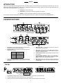
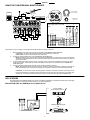
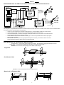
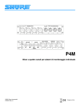
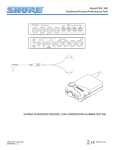
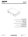
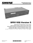
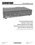
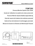
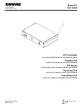
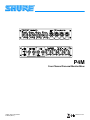
P4M Four-Channel Personal Monitor Mixer 2005, Shure Incorporated 27D8707 (Rev. 4) Printed in U.S.A. ENGLISH WARNING! USING THIS SYSTEM AT EXCESSIVE VOLUMES CAN CAUSE PERMANENT HEARING DAMAGE. USE AS LOW A VOLUME AS POSSIBLE. In order to use this system safely, avoid prolonged listening at excessive sound pressure levels. Please use the following guidelines established by the Occupational Safety Health Administration (OSHA) on maximum time exposure to sound pressure levels before hearing damage occurs. 90 dB SPL at 8 hours 95 dB SPL at 4 hours 100 dB SPL at 2 hours 105 dB SPL at 1 hour 110 dB SPL at 1/2 hour 115 dB SPL at 15 minutes 120 dB SPL — avoid or damage may occur It is difficult to measure the exact Sound Pressure Levels (SPL) present at the eardrum in live applications. In addition to the volume setting on the PSM, the SPL in the ear is affected by ambient sound from floor wedges or other devices. The isolation provided by the fit of quality earphones is also an important factor in determining the SPL in the ear. Here are some general tips to follow in the use of this product to protect your ears from damage: 1. Turn up the volume control only far enough to hear properly. 2. Ringing in the ears may indicate that the gain levels are too high. Try lowering the gain levels. 3. Have your ears checked by an audiologist on a regular basis. If you experience wax buildup in your ears, stop using the system until an audiologist has examined your ears. 4. Wipe the earphones with an antiseptic before and after use to avoid infections. Stop using the earphones if they are causing great discomfort or infection. This symbol indicates that there are important operating and maintenance instructions in the literature accompanying this unit. 3 ENGLISH INTRODUCTION Thank you for buying the Shure P4M Personal Monitor Mixer. The P4M is a half-rack, four channel monitor mixer designed for live performance use. Use it with a Shure Personal Stereo Monitoring (PSMR) system, or in any other application appropriate for a versatile, compact mixer. When used with a PSM system, the P4M provides several enhancements to in-ear monitoring: S S S Consistency – same mix every night, Independence – monitor mixes created and controlled by the performer, Flexibility – provides monitor mixes regardless of a venue’s sound system capabilities. For information on any Shure PSM System, please refer to the appropriate user’s guide, available on the world wide web at www.shure.com. P4M MIXER FEATURES 2 1 P4M FRONT PANEL 4 3 5 6 7 P4M BACK PANEL 1. 2. Input Jacks: Accommodate both XLR and 1/4” connectors at mic or line levels. They are electronically balanced. Signal/Clip LEDs: Color indicates the signal status of the corresponding Mic/Line Input: LED Color 3. Signal Status Green Signal present Yellow Nominal Level Red Signal clipping Concentric Level/Pan Knobs: The inner knob controls the input level; the outer ring pans the input signal between the 1/L and 2/R mix outputs. 8 4. Mix Output Jacks: 1/4” TRS jacks provide the line level mix created with the Level/Pan knobs. 5. AUX Inputs: Signals from the two 1/4” TRS input jacks are combined with the mix created by the Level/Pan knobs. Front panel settings do not affect these jacks. 6. DC IN Locking Connector: Plug the PS40 AC Adaptor into the top connector. 7. DC OUT Locking Connector: Powers a P4T Transmitter or another P4M Mixer. A DC Jumper Cable is provided with the P4M. NOTE: A PS40 can only power two Shure devices. 8. Split Outputs: Each male XLR output provides a duplicate of its corresponding mic/line input. Front panel settings have no effect on Split Outputs. Set Up P4M Back Panel PS40 AC Adaptor 1. 2. 3. Audio Sources To Audio Input of next device Plug the PS40 AC Adaptor into the mixer’s DC IN locking connector. Plug the other end into a wall socket. Connect the MIX OUTPUT jacks to the the audio input of the next device. Connect up to four audio sources (microphones, instruments, mixers) into the input jacks on the front panel. 4 P4M Front Panel ENGLISH USING THE P4M PERSONAL MONITOR MIXER Pans between Mix Out channels DIRECT BOX AUDIO INPUT 3 AUDIO INPUT 1 AUDIO INPUT 2 1/L AUDIO INPUT 4 2/R Adjust levels to Mix Outs (–) (+) AUX IN 2/R Audio signal path for the P4M Mixer AUX IN 1/L MIX OUT 2/R SUM SPLIT OUTPUT 4 MIX OUT 2 MIX OUT 1 SPLIT OUTS SPLIT OUTPUT 1 SPLIT OUTPUT 3 AUX IN 1/L AUX IN 2/R SPLIT OUTPUT 2 LEV PAN LEV PAN LEV PAN LEV PAN MIC/LINE INPUTS Once the basic set up is complete, use the P4M Personal Monitor Mixer to create a custom mix: 1. 2. 3. 4. Mix the signal from each audio input using the corresponding CONCENTRIC LEVEL/PAN knobs: OUTER RING: Use this to pan the signal to the left or right channel of the stereo mix. INNER KNOB: Use this to control the level of the audio input. Observe the signal/clip LEDs next to each CONCENTRIC LEVEL/PAN knob. NOTE: Decrease the level of an input if the corresponding signal/clip LED is consistently red. If the level is decreased all the way and the LED remains red, the level of the input from the previous device in the audio chain is too high and should be decreased. Up to two additional line-level audio sources (such as other mixers, a click track or a digital sequencer) may be added via the AUX IN inputs. These signals go directly to the MIX OUT outputs and are not affected by the CONCENTRIC LEVEL/PAN knobs. To pass an unaltered signal through the P4M, use the corresponding SPLIT OUTPUT. NOTE: Although the P4M does not provide phantom power for condenser microphones, the SPLIT OUTPUTS can pass phantom power from a phantom power supply to a microphone connected to the corresponding input jack. CAUTION!: Use a “direct box” when connecting guitars, keyboards, and other instruments to a mixing console through the P4M Mixer. The phantom power that mixing consoles provide for microphones can damage other instruments. Connect the instrument to the direct box then connect the direct box to the P4M Mixer input. APPLICATIONS The flexible design of the P4M Mixer allows it to be used in many different applications. The following examples introduce principles which will allow you to develop personalized setups for your specific application. APPLICATION ONE: One P4M Mixer to One Audio Device Connect a P4M to audio equipment such as: a PSM Transmitter, –OR– MIX OUTPUTS P4M a PSM Hardwired Bodypack –OR– Ñ Ñ ÑÑ Ñ ÑÑÑ ÑÑ Personal Monitor Mixer INPUTS 1–4 LEVEL/PAN KNOBS 1–4 a Floor Monitor Amplifier. 5 MIX OUT 1/L SUM ENGLISH This is the basic configuration of the P4M Mixer, and is recommended for small ensembles in rehearsal or performance situations: 1. 2. 3. Connect up to four microphones, instruments or audio devices to inputs 1–4 on the front panel of the P4M. Mix the four signals using the LEVEL/PAN knobs adjacent to the inputs. Connect the MIX 1/L OUTPUT and MIX 2/R OUTPUT on the back panel of the P4M to an appropriate piece of audio equipment. APPLICATION TWO: Multiple P4M Personal Monitor Mixers to One Audio Device MIX OUTPUTS AUX INPUTS MIX OUTPUTS P4M Personal Monitor Mixer INPUTS 1–4 To Next P4M Mixer, or a PSM Transmitter, PSM Hardwired Bodypack or Amplifier. P4M Personal Monitor Mixer INPUTS 1–4 LEVEL/PAN KNOBS 1–4 This application, using the P4M’s AUX Inputs, allows more than four inputs to be mixed, and is recommended for larger ensembles in live or rehearsal situations: 1. 2. 3. 4. 5. 6. Connect up to four audio sources into the front panel inputs of a P4M. Mix these signals using the corresponding LEVEL/PAN knobs on the P4M. Connect the MIX OUT outputs of the first P4M to the AUX IN inputs of a second P4M. Connect up to four more audio sources into the front panel inputs of the second P4M Mixer. Mix these signals using the corresponding LEVEL/PAN knobs on the second P4M. Connect the MIX OUT outputs of the second P4M to an appropriate piece of audio equipment. NOTE: If more than eight inputs are required, connect additional P4M Mixers after the second P4M, using the connection described in step 3 above. APPLICATION THREE: Multiple P4M Personal Monitor Mixers to Multiple Audio Devices To Next P4M or Amplifier To Mixing Console To Transmitter, Bodypack or Amplifier Other Audio Sources P4M Personal Monitor Mixer Mixing Console Shared Mic/Line Signal To Mixing Console Monitor Mix To Transmitter, Bodypack or Amplifier Split Outputs 1-4 Mix Outputs P4M Personal Monitor Mixer Monitor Mix Inputs 1–4 Level/Pan Knobs 1–4 This configuration, using the P4M’s SPLIT OUTPUTS, allows each player to hear a custom mix created at their own P4M Personal Monitor Mixer, and is recommended for live, studio or rehearsal situations: 1. 2. 3. 4. 5. 6. Connect a monitor mix (from a mixing console) and up to three microphones or instruments to the four inputs on the P4M Mixer front panel. Connect the P4M SPLIT OUTPUTS containing the monitor mix to an input on a second P4M. Connect the other SPLIT OUTPUTS from the first P4M to either the second P4M or to the mixing console. On the second P4M, connect the SPLIT OUTPUT containing the monitor mix to a third P4M or to a floor monitor amplifier. The other SPLIT OUTPUTS may be connected to a third P4M or to the mixing console. Connect MIX OUT 1/L and MIX OUT 2/R on the back panel of each P4M to an audio device such as a P4T Transmitter, PSM Hardwired Bodypack or a floor monitor amplifier. On each P4M, mix the four signals using the LEVEL/PAN knobs on the front panel. 6 ENGLISH APPLICATION FOUR: One P4M Personal Monitor Mixer to Two PSM Transmitters/Receivers Monitor Mix Other Audio Sources Mix 2/R To Mixing Console Line Inputs PSM LOOP Outputs RECEIVER PSM Mixing Console Transmitter Mix 1/L Split Outputs RF Transmission Mix Outputs Line Inputs P4M RECEIVER PSM Personal Monitor Mixer Inputs 1–4 Transmitter PSM RF Reception Level/Pan Knobs 1–4 Monitor Mix This configuration, using the P4M’s SPLIT OUTPUT and a PSM transmitter’s LOOP OUTPUT, allows one P4M to provide custom mixes to two PSM transmitters, and is recommended for small ensembles in live performance: 1. 2. 3. 4. 5. Connect up to four microphones or instruments into the P4M inputs. Connect the SPLIT OUTPUTS to a mixing console. Connect a monitor mix from a mixing console to the first PSM transmitter (P4T transmitter shown). On the first PSM transmitter, connect the LOOP output containing the monitor mix to an input on the second PSM transmitter (See appropriate PSM System User’s Guide for details). Connect a MIX OUT output to each transmitters’ remaining input. Use the front-panel PAN knobs to balance input signals between the two transmitters. Place the PSM receivers in MixMode (see appropriate PSM System User’s Guide). Use the balance wheel on the PSM receiver to blend the monitor mix with the custom mix created by the P4M. RACK MOUNTING THE P4M PERSONAL MONITOR MIXER The P4M features a 1/2-rack chassis specially designed for sturdiness. This eliminates the sagging and bending found in most designs — the brackets and straddle bars ensure that the units will be installed securely. 1/ -rack 2 WARNING: Do not torque the screws too tightly, or the chassis may be damaged. Single Unit ÑÑ ÑÑ ÑÑ ÑÑÑÑÑ ÑÑÑ ÑÑÑ ÑÑ ÑÑ ÑÑ ÑÑ ÑÑÑ ÑÑ ÑÑ Ñ Ñ ÑÑÑÑÑ ÑÑÑÑ Ñ ÑÑÑÑ Ñ Ñ Ñ ÑÑÑÑÑÑ ÑÑÑÑ Ñ ÑÑ ÑÑÑÑÑÑÑ Ñ Dual-Mounted Units ÑÑÑ ÑÑÑÑÑ ÑÑ ÑÑÑÑ ÑÑ ÑÑÑÑÑ ÑÑÑ ÑÑÑ ÑÑ Ñ Ñ ÑÑÑÑ Ñ Ñ ÑÑ Ñ ÑÑÑ ÑÑ ÑÑÑ ÑÑ ÑÑ ÑÑÑ Ñ ÑÑ ÑÑÑ Ñ ÑÑÑ ÑÑÑÑÑ ÑÑÑÑ ÑÑÑÑ Ñ ÑÑÑ ÑÑÑÑÑ Ñ ÑÑ Ñ NOTE: Be sure to use both straddle bars when installing dual units. Mounting in an Equipment Rack ÑÑÑ ÑÑ ÑÑÑÑÑ Ñ ÑÑÑ Ñ ÑÑÑ ÑÑ ÑÑÑ Ñ ÑÑÑ ÑÑÑÑÑÑ ÑÑÑÑ ÑÑÑÑÑ ÑÑÑ Ñ ÑÑ ÑÑÑÑÑ Ñ ÑÑ ÑÑÑÑ ÑÑ Ñ ÑÑ ÑÑÑÑÑ Ñ ÑÑ Ñ ÑÑÑÑÑ ÑÑ ÑÑÑ ÑÑ Ñ Ñ ÑÑ ÑÑÑÑÑÑÑÑÑÑ ÑÑÑ Ñ 7 ENGLISH Specifications Measurement Conditions (unless otherwise specified): full gain; 1 kHz, one channel activated; source impedances: Mic 150 Ω, Aux Level 150 Ω; terminations: Line 600 Ω. Frequency Response (Ref 1 kHz, controls centered) 20 Hz to 20 kHz ± 2 dB INPUT Specifications Input 1–4 (front panel) Aux In Gain (Maximum) 43 dB 0 dB Impedance (at 1kHz) 5800 Ω 18 kΩ (each) 9100 Ω (1/L mono) Input Clipping Level +12dBV +12 dBV Crosstalk -100 dB -90 dB Common Mode Rejection > 75 dB > 70 dB OUTPUT Specifications Output Split 1–4 Mix Out Impedance N/A 500 Ω (unbalanced) 1kΩ (balanced) Output Clipping Level N/A +5 dBV (10 kΩ balanced load, -30 dBV input ch. 1–4.) Noise (100 Hz to 22 kHz) -110 dBV -100 dBV (all controls CCW) -62 dBV (all controls CW) Distortion (THD) at 1kHz) .0005% < .05% (0 dBV output) Crosstalk -100 dB -70 dB LEDs: Resultant Mix Out Level Green: -30 dBV Yellow: -10 dBV Red: 0 dBV Phantom Power The P4M does not produce phantom power, but phantom power is allowed to pass through Split Outputs 1–4 to inputs1–4 respectively. Audio Polarity All outputs in polarity with all inputs. XLR Pin 2 is “hot” with respect to Pin 3; Pin 1 is ground. 1/4” TRS tip is “hot” with respect to ring; sleeve is ground. Temperature Range Operating . . . . . . . . . . . . . . . . . . . . . . . . . . . -7° to 49° C (20° to 120° F) Storage . . . . . . . . . . . . . . . . . . . . . . . . . . . -29° to 74° C (-20° to 165° F) Overall Dimensions 44 mm H x 218 mm W x 162 mm D (1.72 x 8.60 x 6.37 inches) Net Weight 1.20 Kg (2 lbs, 10 oz) Current 120 mA max. Power Requirements Operating voltage 14–18 Vdc Supplied with one of the following external power supplies: S Model PS40: 120 Vac, 60 Hz input S Model PS40E, Model PS40UK: 230 Vac, 50/60 Hz input NOTE: Courtesy DC connector is protected from short by a self–resetting “Polyfuse”. Maximum recommended load is 250mA. (2 P4Ms or 1 P4T.) Certification P4M: Eligible to bear CE marking: . Conforms to European Union EMC directive 89/336/EEC. Meets applicable tests and performance criteria in European Standard EN 55103 (1996) parts 1 and 2, for residential (E1) and light industirial (E2) environments. PS40: Conforms to applicable U.S. and Canadian electrical and safety standards. PS40E/PS40UK: Conforms to European low voltage directive 72/23/EEC. Eligible to bear CE marking. Furnished Accessories Single Mount Rack Bracket . . . . . . . . . . . . . . . . . . . . . . . . . . . . . . . . . . . . . . . . . . . . . . . . . . . . . . . . . . . . . . . . . . . . . . . . . . . . . . . . . . . . . . . . . . . . . . . . 53A8484 Dual Mount Rack Bracket . . . . . . . . . . . . . . . . . . . . . . . . . . . . . . . . . . . . . . . . . . . . . . . . . . . . . . . . . . . . . . . . . . . . . . . . . . . . . . . . . . . . . . . . . . . . . . . . . . 53B8484 Straddle Bars . . . . . . . . . . . . . . . . . . . . . . . . . . . . . . . . . . . . . . . . . . . . . . . . . . . . . . . . . . . . . . . . . . . . . . . . . . . . . . . . . . . . . . . . . . . . . . . . . . . . . . . . . . . . 53A8443 AC Adaptor . . . . . . . . . . . . . . . . . . . . . . . . . . . . . . . . . . . . . . . . . . . . . . . . . . . . . . . . . . . . . . . . . . . . . . . . . . . . . . PS40 (120V), PS40E (230V), PS40UK (230V) DC Jumper Cable . . . . . . . . . . . . . . . . . . . . . . . . . . . . . . . . . . . . . . . . . . . . . . . . . . . . . . . . . . . . . . . . . . . . . . . . . . . . . . . . . . . . . . . . . . . . . . . . . . . . . . . 95A8420 8 SHURE Incorporated http://www.shure.com United States, Canada, Latin America, Caribbean: 5800 W. Touhy Avenue, Niles, IL 60714-4608, U.S.A. Phone: 847-600-2000 U.S. Fax: 847-600-1212 Intl Fax: 847-600-6446 Europe, Middle East, Africa: Shure Europe GmbH, Phone: 49-7131-72140 Fax: 49-7131-721414 Asia, Pacific: Shure Asia Limited, Phone: 852-2893-4290 Fax: 852-2893-4055