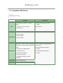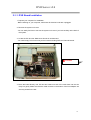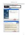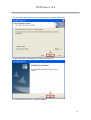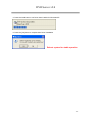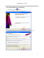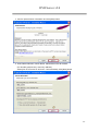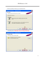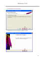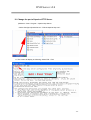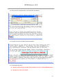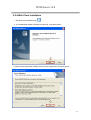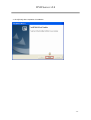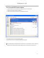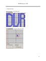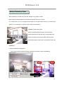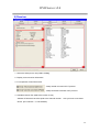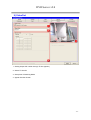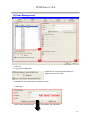
1
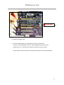
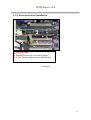
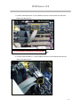
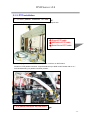
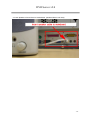
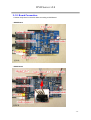
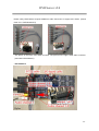
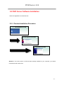
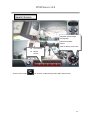
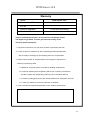
User Manual
DVR Server v2.0
Digital CCTV System
DVR Server v2.0
Safety Precaution:
z Make sure switching the power off before you install the DVR
board
z There is possibility of electric shock inside of the DVR, please
avoid opening the unit if you are not qualified service personnel
z While the DVR is under removing, storing or using, please avoid
any vibration or strike
z Do not store under the direct sunlight or near by heating
z Avoid humid, dusty or smoky environments
z Avoid extremly hot or cold areas
z This equipment should not be exposed to water or other liquids
z Install the DVR in a well-ventilated area
z Avoid excessive electronic or magnetic fields
-2-
DVR Server v2.0
Limited Warranty
This product is warranted against manufacturing defects for the period of one year.
The warranty period commences on the date of purchase from the authorized
reseller/retailer.
You original purchase invoice, showing the date of purchase of the product is your proof
of the date of purchase.
During the warranty period, defective parts will be repaired or replaced.
There will be no
charge for labor or pats during the one-year warranty period from the date of purchase.
Any shipping or other cost such as customs incurred costs, etc…. is customers’
responsibility.
This warranty does not cover any failure resulting in loss to SW, data, lost profits, lost
saving any incidental damages or other economic consequential damages due to
accident, abuse, misuse, and negligence.
Technical Support and Service
For warranty service and assistance, it is recommended that you contact the place of
purchase to arrange for return and/or repair the product.
-3-
DVR Server v2.0
Table of Contents
Chapter 1 Introduction
Page
1-1. General Guidelines
6
1-2. System Requirements and Description
6
1-3. Compatible HW Device
7
Chapter 2 Installation
2-1. Hardware Installation
-8-
2-1-1. DVR Board Installation
-9-
2-1-2. Extension Board Installation
-11-
2-1-3. Pan/Tilt/Zoom Installation
-13-
2-1-4 Audio Installation
-17-
2-1-5 Board Connection
-19-
2-2. Software Installation
-21-
2-2-1 Installation Procedure
-21-
2-2-2. Install DVR Server
-22-
2-2-3 Apache Web Server Installation
-26-
2-2-4 WebClient Installation
-32-
2-2-4. Uninstall DVR Server
-34-
-4-
DVR Server v2.0
Chapter 3 User Manual for DVR Server
※ Preview of DVR Server v2.0 Screen Mode
Monitoring screen Mode of DVR Server
Search screen mode of DVR Server
3-1. Main features and functions
-35-
3-2 Access prevention
-37-
3-3. Monitoring Screen Mode
-38-
※ DVR System Configuration
-41-
1) General
-41-
2) Channel
-43-
3) Store
-45-
4) Network
-47-
5) Schedule
-50-
6) Maintenance
-52-
7) Event
-53-
8) Receiver
-56-
9) VideoOut
-57-
10) User Management
-58-
3-4. Search Mode
-60-
※ Print Image
-61-
※ How to use Watermarking
-63-
※ Search
-67-
Chapter 4 Warranty
※ Warranty
-69-
-5-
DVR Server v2.0
Chapter 1: Introduction
Chapter 1
Thank you for purchasing DVR. This manual will provide detailed instructions on how to install and
program the DVR to your specific application. Please read this manual carefully prior to install and
programming the DVR.
1-1. General Guidelines
Chapter 1: System Requirements and Compatible H/W information
Chapter 2: DVR Hardware, Software Installation
Chapter 3: How to use DVR Server program
Chapter 4: Warranty
1-2. DVR System Requirements
PC
-
OS : Windows 2000 (Require DirectX 8.1 or higher) and Windows XP
Please install 8.1 version of DirectX before install DVR Server Program
on Server PC for Windows 2000 Only
-
CPU : Intel Pentium IV 2.4GHz/ Cel 1.7GHz or higher
-
RAM : 256MB or higher
-
Network : 10 /100Mbps LAN, Modem, xDSL
System Description
Digital Surveillance System is a PC based monitoring system. It exceeds the capabilities of
traditional analog switchers, multiplexers, and time-lapse VCRs. The system is able to connect up
to 16 cameras with each at the highest frame rate, records high-quality digital video based on
motions. The system offers digital recording, remote camera viewing access, video archiving, and
multi-camera display. The system supports PTZ camera.
-6-
DVR Server v2.0
1-3. Compatible HW Device
Compatible
Intel Pentium Process (x86, 1.7GHz or
higher)
CPU
- Intel Celeron 1.7GHz or higher
Incompatible
- Lower than Intel Pentium Process
1.7GHZ
- Other than x86
- Intel Pentium IV
With one or more PCI slot, supporting Intel - Other than Intel Chipset Boards
Pentium processor
Main Board
- Intel 84x Chipset
- Intel 85x Chipset
With 8MB or higher memory, Supporting - Intel 81x Graphics controller(OnBoard)
16Bit Color and YuY2 DirectX Mode (8.0 or
higher)
- ATI Expert 2000 32MB SDRAM
Graphic Card
- ATI Radeon System
- nVidia Riva TNT2 System
or Intel i740
- VIA Chipset(OnBoard) Graphics
controller.
- SIS Chipset(OnBoard) Graphics
controller.
- nVidia Geforce System
- Intel 845G/GL Graphics controller
(OnBoard).
Sound Card
HDD
All PCI & OnBoard Type
HDD 5400RPM or higher
-7-
DVR Server v2.0
Chapter 2: Installation
Chapter 2
2-1 Hardware Installation
Caution: Static electricity can damage electronic circuitry. To avoid static
discharge, touch a grounded metal object (i.e. your PC case) or wear a
grounding strap connected to a ground source.
Make sure Power and cables are connected properly otherwise it may cause
damage to the equipment (not cover under warranty). Always turn off the
PC power before connecting or disconnecting any jumper or cable on the
drive.
- Next Page -
-8-
DVR Server v2.0
2-1-1. DVR Board Installation
1. Prepare your computer for installation.
: Before working on your computer, make sure all electrical cords are unplugged.
2. Remove the system unit cover.
: You can easily find how to remove the system unit cover if you look carefully at the back of
the system.
3. Locate the PCI bus slot. Make sure this slot is unobstructed.
: You need empty PCI slot as many as the boards including DVR and channel boards.
① PCI slot
1
4. Place the board directly over PCI slot and insert one end of the card down into the slot
firmly but gently. Make sure that the metal contacts on the bottom of the host adapter are
securely seated in the slot.
-9-
DVR Server v2.0
1
① DVR board
5. Fasten the bracket screw.
6. Connect channel board to 5~8ch parallel connector on DVR board
Position of ‘channel parallel connector’ might be different up to DVR model.
Please refer to ‘2.1 DVR board is drawing’ for parallel connector position.
All the optional channel boards and channel board cables are same and alternative.
-10-
DVR Server v2.0
2-1-2. Extension board Installation
3
2
1
1: Channel Cable
2: Parallel Connector on channel board
3: 5~8ch Parallel Connector on DVR board.
- Next page -
-11-
DVR Server v2.0
7. Connect channel board to ‘9~12ch parallel connector on DVR board’ and insert the
channel into the PCI slot.
1: 9~12ch parallel connector on DVR board
8. Connect channel board to ‘13~16ch parallel connector on DVR board’ and insert the
channel into the PCI slot.
1
-12-
DVR Server v2.0
2-1-3. PTZ installation
]
1: 13~16ch
parallel
on DVR
A. PTZ
Cable connector
Connection.
1. Insert the plug of PTC cable into the PC case through proper hole.
① Plug of PTZ cable
② 485 cable of PTZ cable
③ Serial Port of PTZ cable
3
2
2. Insert the plug of PTC cable into the ‘PTZ parallel connector on DVR board’.
Position of ‘PTZ parallel connector’ might be different up to DVR model. Please refer to ‘2.1
DVR board drawing’ for parallel connector position.
1
1: PTZ parallel connector on DVR board
-13-
DVR Server v2.0
3. Locate the empty serial comport on rear side of PC.
1
2
1: Serial Comport 1 or 3
2: Serial Comport 2 or 4
4. Insert the serial port of PTZ cable into empty serial port of PC.
1
1: Serial port of PTZ cable
-14-
DVR Server v2.0
5. Connect 485+ cable of PTZ cable with 485+ cable of PTZ camera and 485- cable of PTZ cable
with 485- cable of PTZ camera. And, insulate them with insulating tape.
1
2
1 : 485+ cable connection
2 : 485- cable connection
6. Connect video signal cable of PTZ camera with BNC jack on DVR.
7. Address of PTZ camera should be identical to DVR channel. In the Fig 4.11, the address
of PTZ camera should be set as ‘1’, because camera is connected to No.1 channel.
- Next page -
-15-
DVR Server v2.0
1
1: BNC Jack of Channel
8. Connect the adaptor with PTZ camera.
-16-
DVR Server v2.0
2-1-4. Audio installation
1. Insert MIC to sound card OR DVR board.
<The following description is of 1CH Audio example.>
MIC is inserted to PC Mainboard. (Standard color red hole)
OR Insert MIC to DVR Board.
-17-
DVR Server v2.0
2. Insert Speaker to Sound Card of motherboard. (standard Green color hole)
-18-
DVR Server v2.0
2-1-5. Board Connection
1. Please notify board connection differs according to DVR Board.
- SDVR Board
- HDVR Board
-19-
DVR Server v2.0
Please notify HDVR Board requires additional Audio Connector to support 5CH Audio. (Sound
Card 1CH + DVR Board 4CH)
- The picture on the left is 4CH audio connector. The picture on the right is 8CH audio connector.
(used with HPLUS Board.)
- HPLUS Board
-20-
DVR Server v2.0
2-2 DVR Server Software Installation
Select one application to install at a time
2-2-1. Preview Installation Procedure
1. Install DVR Server SW
2. Install Apache HTTP SW
3. Install WebClient SW
Attention: If an older version of SW has been already installed on your computer, you should
uninstall the older version first.
-21-
DVR Server v2.0
2-2-2. Install DVR Server Software (Important)
Installation
Procedure
Run the Setup.exe (
1. Install DVR Server SW
2. Install Apache HTTP SW
3. Install WebClient SW
) file.
1. Install Shield Wizard is executed. Press the [Next] button
-22-
DVR Server v2.0
2. If you accept all the terms of the License Agreement, Press the [Yes] button
3. Select the folder of destination and Press the [Next] button.
4. Press the [Finish] button to complete installation.
-23-
DVR Server v2.0
5. Press the Install button to run Driver Auto installer for Win 2000/XP.
6. Press the [Yes] button to complete Auto Driver Installation
Reboot system for stable operation
-24-
DVR Server v2.0
2-2-3. Apache Web Server Installation
1. Run Apache Web Server[
] program.
2. The screen will display as following: Click [Next] button.
3. Read the license agreement. If you agree click [I accept…] and click [Next] button.
-25-
DVR Server v2.0
4. Confirm Apache Server information and click [Next] button.
5. Insert Network Domain, Server Name, Administrator’s Email Address.
(For formality purpose only. Insert any address.)
Select [Run as a service for All Users – Recommended]. Click [Next] button.
-26-
DVR Server v2.0
6.Select [Complete] for Setup Type. Click [Next] button.
7. Click [Next] button. Attention: Do not change directory.
-27-
DVR Server v2.0
8. Click [Install] button and start installation.
9. Click [Finish] button when completion of installation program.
-28-
DVR Server v2.0
10. Change the port of Apache HTTP Server.
(Windows – Start - Program – Apache Http Server
– Select Configure Apache Server – Edit the Apache Http conf…
11. The screen will display as following: Select Edit – Find.
-29-
DVR Server v2.0
12. Insert “port 80” and press enter. Port 80 will view as following:
13. Change Port 80 to Port 26540 and save Notepad.
14. Exit Notepad after Save.
z
Attention: Must add port number after IP address to view in Internet Web Browser.
z
Ex) http://211.104.32.107:26540
-30-
DVR Server v2.0
2-2-4.Web Client Installation
1. Run Web Client installation file (
).
2. The InstallShield Wizard will display as following: Click [Next] button.
3. Read License Agreement carefully. When accept of agreement click [Yes] button.
-31-
DVR Server v2.0
4. Click [Finish] after completion of installation.
-32-
DVR Server v2.0
2-2-4. Uninstall DVR Server program
1. Under the Start menu in Windows, go to Setting and then to Control Panel
2. Double click the Add or Remove Programs
3. Select DVR System Plus and Click on Change/Remove button.
3. Click Remove button and Press the [Next] button.
4. Press the Finish button to complete uninstalling DVR program.
※ The uninstall program will delete all DVR system files on your hard disk. However, it does not
delete the video images and the log files already saved in the hard drive of your DVR PC.
-33-
DVR Server v2.0
Chapter 3 User Manual for DVR Server v2.0
Monitoring Screen (Main View) Mode
Search Screen Mode
View Screen
Search Screen
-34-
DVR Server v2.0
3-1 Main features and functions
1. Operating System (O/S)
DVR system uses Windows 2000/XP as a basic OS and is designed to operate all needed
functions of DVR System properly.
2. Main Program
The main program operates Search, Backup, Recording, and every function to control DVR
System and it has the following functions and features
1) Easy to search
According to date, time, and camera, the user is able to execute instant, speedy, conditional,
and magnified searched video images.
2) Backup & Print function
Able to print out searched images and provides Backup function
3) Switcher (Auto –Selector) function
4) Split-screen display Function
The user is able to select the following screen division: 1, 4, 6, 8, 9, 10, 13, 16, and full screen
5) Recording speed adjustment function
The user is able to adjust recording rate
6) Recording image quality setup function for each CH
Able to manage HDD space efficiently by adjusting recording image quality for each channel
7) Motion Detection Function (MD)
The user is able to setup motion area, and record the image when the motion image is
detected in the area.
(Motion-driven recording)
8) PAN/TILT/ZOOM Control Function
P/T/Z built in the system (Requirement of Receiver Device)
9) Alarm connection with Camera & Sensor
Connect with emergency bell and alarm while MD & Sensor are operating
-35-
DVR Server v2.0
10) Watch Dog
When system function does not operate properly or in case of emergency shutdown, watchdog
function enables auto-rebooting/restoration of existing data
11) WaterMark
A copyright-protection of embedding a code into a digital audio or video file to attempt to
prevent image tampering
12) Image Transmission
Image transmission to remote site by using PSTN network
(Able to monitor remote sites from Web Browser OR NetClient program)
13) Resolutions
Support 320×240 pixels, 640x480 pixels
14) Schedule
Schedule setup by date/time
(recording by time, MD schedule recording, sensor schedule recording)
15) Sensor Input, Digital-Output via alarm
16) Basic ID/Password function
-36-
DVR Server v2.0
3-2 Access Prevention
TIP>
Q : ”Cannot access” message is on the screen.
A : DVR is set to lock on mode.
<How to unlock DVR server>
1. Click configuration button.
2. Insert ID and PW.
< Default ID = admin
PW = admin >
-37-
DVR Server v2.0
3-3 Monitoring Screen Mode
1 : Standard Display Screen
)
2 : 1CH recording screen (represented by
3 : Schedule Motion Detection Recording Screen (represented by
)
4 : Motion Detection Store Screen (represented by
5, 6 : Please refer to full description as below
- Next Page -
-38-
DVR Server v2.0
5 Full Description (Part A)
Present Date/Time
Operating CH Display Icon :
Un operating CH Display Icon :
Recording CH Display Icon :
REC : Recording
ALL : Select all
4 CH Split-Screen
6 CH Split-Screen
Mode
Mode
8 CH Split-Screen
9 CH Split-Screen
Mode
Mode
10 CH Split-Screen
13 CH Split-Screen
Mode
Mode
16 CH Split Screen Mode
Auto-Switching Mode
Automatically switch to next screen through periodic
time
Full Screen Display Mode
Light
On/Off
Auto Pan
P/T/Z
Power
-39-
DVR Server v2.0
6 : Full Description (Part B)
1 : Search Mode
2 : Configuration button
3 : Lock button
4 : Check Log record
Indicate item under LAN / MODEM connection
LAN: support simultaneous connection up to max. 100 users
MODEM: support one user
5 : DVR Power (On / Off)
6 : Audio Volume Control.
-40-
DVR Server v2.0
Double Click on configuration (
) icon in Main View Screen
Configuration
1) General
1. Start Windows
: Automatically execute program when start of Windows
: Execute Full Screen Size when run DVR program
2. Exit DVR program
: Only exit DVR Program
: Restart Windows when exit DVR program
: Shutdown Windows when exit DVR program
3. Audio volume control
: Audio volume setting
: Setup volume for AUD 1 ~ AUD8
: Snd Card = Setup Sound Card volume.
-41-
DVR Server v2.0
4. Camera and audio configuration
1 : Select camera type (NTSC, PAL)
2 : Select camera channel
3 : Select display resolution for each camera channel
4 : Select audio device
5 : Indicate technical support information
<TIP>
1. Video Resolution
320x240
640x480
SDVR
16CH
16CH
HDVR
16CH
16CH
HPLUS
16CH
Support up to 6CH
2. Audio
SDVR
Support up to 2CH
HDVR
Support up to 5CH
HPLUS
Support up to 9CH
-42-
DVR Server v2.0
2) Channel
1. Selecting the camera CH/Apply change to all camera CH
2. Insert the place name of selected camera
3. Switching delay time for screen-partition mode
4. (Search Screen)
(Monitoring Screen)
-43-
DVR Server v2.0
5 : Assign control color tone
(Direction)
Click color you wish to change
Select Color you wish to change and then click confirmation button
6 : Select you wish to change character form, and size
7 : Preview selected result from step (
) ~ to step (
)
8 : Adjust Picture Quality
-44-
DVR Server v2.0
3) Store
1 : Check the HDD where you want to use for storage
2 : Indicates total HDD space for selected HDD in [1].
3 : Select to use overwrite function
EX>
Start to overwrite when HDD Free space becomes 512 MB
4 : Display Picture Quality and Setting stored-frame
Display frame number of each channel (30Frame per Second)
: Higher FPS provides more natural image
Setting compress quality
-45-
DVR Server v2.0
5 : Watermark Setup
: Select Watermark
: Display DVR Mark as default image
: The user can define own mark
-46-
DVR Server v2.0
4) Network
1.: Network Server
: Use LAN
: Use MODEM
2 : Indicates DVR IP address and MAC address.
3.: Limit of possible simultaneous client connection
Network Access Port: Select Port No. while Client is accessing to Server
Max. Accessing User Number: Assign Accessing User Number (Max. 100 Client number)
-47-
DVR Server v2.0
★ Register Dynamic IP
: Service for dynamic IP users
DHS ( Dynamic Host Services)
Dynamic IP users IP address changes frequently which causes inconvenience to check IP
address each time when connection. DHS executes a role as fixing Dynamic IP to Static IP.
For DHS(Dynamic Host Services) registration please visit http://chainip.com/eng.
* Please notify DHS is paid services.
) part is not activated:
For Dynamic IP users when (
Please click ‘register Dynamic IP by force’
For Sharing IP users
: Please click ‘User of Sharing IP’
4. IP Manager setup
IP Manager configuration
Disable : Allow any IP for connection.
White IP : Allow selected IP for connection.
Black IP : Prohibit connection of selected IP.
-48-
DVR Server v2.0
★ Network Configuration ★
(White IP setup)
< 설정 전 >
< Before setup >
< After setup >
1 : Click White IP in [1].
2 : If ‘Add IP’ is activated please insert IP address.
3 : Cllick [2] button and IP address will be added to White IP List.
(Black IP setup)
< Before setup >
< After setup >
1 : Click Black IP in [1].
2 : If ‘Add IP’ is activated please insert IP address.
3 : Click [2] button to add IP in Black IP List.
-49-
DVR Server v2.0
5) Schedule
1, 3 : Setup Recording, MD, Sensor schedule.
2 : Choose channel in [1].
[1, 3 Schedule setup]
Draw>
Click Mouse-Left button to Drag
Erase>
Click Mouse-Right button to Drag
-50-
DVR Server v2.0
-51-
DVR Server v2.0
6) Maintenance
1 : Display Windows Information (OS, CPU, RAM)
2 : Display DVR Information
3 : Display operating program contents of DVR System
4 : Select Data Verification as run DVR program
Normal Check Mode: Ordinary Check (Fast Checking Speed)
Full Check Mode: Detail Check (Slow Checking Speed)
5 : Auto reboot system
.
-52-
DVR Server v2.0
7) Event
1 : Select camera channel you wish to change
Click Apply All button to apply all channels
2 : Setting up Sensor of existing operating camera channel (Optional)
3 : Setting up Digital Output(Optional)
4 : Select any Warning Sound.
(Item 2, 3, 4) applies only when I/O installed in DVR
5 : Duration of warning time when sensor input.
-53-
DVR Server v2.0
Motion Detection Store
Motion detection is to detect any relevant changes in the image or video.
Motion detection demonstrates how sensitive peripheral version is to motion.
At a certain point, you can no longer see the object. If the object starts moving, you will become
aware of it, even though you could not see it while it was stationary.
<Picture 1> MD Setting Area
Mouse-Left button Drag and Drop: Select MD Area
Mouse-Right button Drag and Drop: Unselect MD Area
Mouse Left button Double Click: Select all of the Area
Mouse Right button Double Click: Unselect all of the Area
<Picture 1>
6 : Motion Detection Configuration
- Check Point : Motion Detection Display, MD Driven-Recording, Draw Small MD Box
-54-
DVR Server v2.0
- Check Point : Display MD, Record MD images
- Check Point : Record MD images
7 : MD Sensitivity Setting
-55-
DVR Server v2.0
8) Receiver
1 : Select the serial port to use (COM1,COM2))
2 : Display current receiver information
3 : For expansion of Pan/Tilt function
: Swap vertical command of P/T protocol.
: Swap horizontal command of P/T protocol.
4 : Available receiver list: (Select the receiver to use)
Address of Receiver has to be equal to the channel number. Also you have to use same
device. (EX: Channel 1 => HW Address)
-56-
DVR Server v2.0
9) VideoOut
1 : Setting Output CH number through TV-Out (Option)
2 : Select TV-Out CH
3 : Setup time of Switching Mode
4 : Appear Preview Screen
-57-
DVR Server v2.0
10) User Management
1 : User List
2 : Log In/Out management
: Automatic log out function after setup time
: Enable login & out function.
3 : Authorization of local functions and remote control
< Add users >
: Insert User ID and Password
Click ‘Modify user information.’
-58-
DVR Server v2.0
: Choose accessibility for
DVR Server.
: Choose accessibility for remote Client program..
-59-
DVR Server v2.0
3-3 Search Screen Mode
1:
2:
Playback, Rewind, 2X Playback
= Save selected screen as image
Choose where to save image file and write file name
-60-
DVR Server v2.0
Print
= Print Images
Print Setup
1 : Preview Printing Images
2 : Able to print maximum of 8 selected camera channels
3 : Printer Setup Option
-61-
DVR Server v2.0
<Print Configuration>
Click the [OK] button to print
4 : 1 CH original copy size
1 channel image print out
1channel double size image print out
2 channels double size images print
4 channels images print out
8 channels images print out
-62-
DVR Server v2.0
Watermark
: Watermark Icon
Direction to use Watermark
1. Save image from search screen and view screen
Save image before you run WaterMark Viewer
program.
- Next Page -
-63-
DVR Server v2.0
2. Click the watermark (
) icon from searched Screen Mode
Open File to bring saved data
Open File
Save
image
from
View
Screen and Search Screen
※ (Watermark)
A copyright-protection of embedding a code into a digital audio or video file to attempt to thwart
piracy or unlicensed use
A watermark is a normally invisible pressure mark in expensive paper which can be seen only
when the paper is held up to the light. Some computer files have digital watermarks embedded in
them as a pattern of bits which appear to be part of the file and are not noticeable to the user.
These patterns can be used to detect unauthorized copies.
An identification code or bit pattern integrated into multimedia data that aids copyright owners in
identifying illegally distributed audio, video, or image data.
-64-
DVR Server v2.0
3.Click the [WM Detect] to watermark
Image has not been tampered
1 : Show saved image.
2 : Show defined Mark by user at Configuration Mode
3 : Show Mark hidden in real image
4 : Show information related to image (Size, file formation time, modified time, process time)
RESULT : It is an Original Image !!
= Show that images has not been tampered
5 : WM Detect button
-65-
DVR Server v2.0
Image has been tampered
Tampered date
Tampered Area
1 : Show saved image
2 : Show defined value of Watermark from Configuration Mode
Display X Mark as tampered image was detected
3 : Show Mark hidden in image (Display read color at tampered area)
4 : WM Detect Button
5 : Show image information size, reading time, writing time)
RESULT : The Image File was abused!! (Image has been tampered)
-66-
DVR Server v2.0
Search
1. Move to Search Screen Mode and then Click the calendar (
) Icon
Date of saved data
Current Date
2. Select Search Date and then Click [Load] button
-67-
DVR Server v2.0
Search Screen
Playback saved images
2X Playback
Reverse Playback
Pause
Search data by each frame
z
Hour Search
z
Minute
Search
Click the view mode (
) icon to return to Monitoring Screen (Main View Screen)
-68-
DVR Server v2.0
Warranty
Model
DVR Server v2.0
Manufactured Date
Lot. No
Period of Warranty.
1 Year after purchasing
Purchased Date
It was a qualified item to pass a strict inspection and Quality control.
If it happen any problem, it will be guaranteed according to the
following written description.
1. The period of warrant is one year from the date of purchasing this item.
2. In case of deficit in manufacture, when happening trouble spontaneously,
We are ready to exchange or free-repairing refund or compensation.
3. If will fix up the system at Actual expense even though it in the period of
Warranty as following cases;
A. Mistake in using this system or trouble by handling carelessness
B. Trouble by repairing and reorganizing without our company is Permission,
Trouble to repair and reorganizing system by other companies Service
C. Troubles or Damages by due to the natural disaster Fire, earthquake, flood etc.
D. A case of Troubles by Customer’s attention of mistakes
4. If you would like to request the Application of A/S. Please contact below.
-69-