1
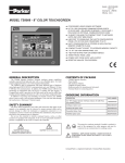
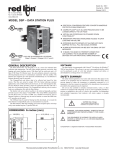
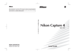
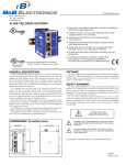
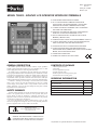
Bulletin HP471055U003 Issue 1.0 Drawing No. LP0874X Effective 10/11 MODEL TS8003 - GRAPHIC LCD OPERATOR INTERFACE TERMINALS CONFIGURED USING DSI8000 SOFTWARE UP TO 5 RS-232/422/485 COMMUNICATIONS PORTS (2 RS-232 AND 1 RS-422/485 ON BOARD, 1 RS-232 AND 1 RS422/485 ON OPTIONAL COMMUNICATIONS CARD) 10 BASE T/100 BASE-TX ETHERNET PORT TO NETWORK UNITS AND HOST WEB PAGES USB PORT TO DOWNLOAD THE UNIT’S CONFIGURATION FROM A PC OR FOR DATA TRANSFERS TO A PC UNIT’S CONFIGURATION IS STORED IN NON-VOLATILE MEMORY (4 MBYTE FLASH) COMPACTFLASH® SOCKET TO INCREASE MEMORY CAPACITY 3.2-INCH 128X64 PIXEL LCD WITH YELLOW LED BACKLIGHT, ABLE TO SUPPORT TEXT AND SIMPLE GRAPHICS OUTDOOR UNIT WITH UV RATED OVERLAY AVAILABLE 32 BUTTON KEYPAD WITH USER IDENTIFIABLE KEYS, NAVIGATIONAL KEYS, NUMERIC KEYS, KEYS FOR ON-SCREEN MENUS, AND OTHER VARIOUS KEYS. THREE FRONT PANEL LEDS POWER UNIT FROM 24 VDC ±20% SUPPLY GENERAL DESCRIPTION CONTENTS OF PACKAGE The TS8003 Operator Interface Terminal combines unique capabilities normally expected from high-end units with a very affordable price. It is built around a high performance core with integrated functionality. The TS8003 is able to communicate with many different types of hardware using high-speed RS232/422/485 communications ports and Ethernet 10 Base T/100 Base-TX communications. In addition, the TS8003 features USB for fast downloads of configuration files and access to trending and data logging. A CompactFlash socket is provided so that Flash cards can be used to collect your trending and data logging information as well as to store larger configuration files. In addition to accessing and controlling of external resources, the TS8003 allows a user to easily view and enter information. The unit uses a Liquid Crystal Display (LCD) module, which is easily readable in both indoor and outdoor applications. Users can enter data through the front panel 32-button keypad that has user identifiable keys. - TS8003 Operator Interface. - Panel gasket. - Two user legendable key sheets. - Template for panel cutout. - Hardware packet for mounting unit into panel. - Terminal Block for connecting power. ORDERING INFORMATION SAFETY SUMMARY All safety related regulations, local codes and instructions that appear in the manual or on equipment must be observed to ensure personal safety and to prevent damage to either the instrument or equipment connected to it. If equipment is used in a manner not specified by the manufacturer, the protection provided by the equipment may be impaired. Do not use the controller to directly command motors, valves, or other actuators not equipped with safeguards. To do so can be potentially harmful to persons or equipment in the event of a fault to the controller. DESCRIPTION PART NUMBER Operator Interface for indoor applications only, textured finish with embossed keys TS8003/00/00 CANopen Option Card 8000/CB/00/00 Profibus DP Option Card 8000/PB/00/00 DeviceNet Option Card 8000/DN/00/00 FireWire Option Card 8000/FA/00/00 CAUTION: Risk of Danger. Read complete instructions prior to installation and operation of the unit. WARNING - EXPLOSION HAZARD - SUBSTITUTION OF COMPONENTS MAY IMPAIR SUITABILITY FOR CLASS I, DIVISION 2/CLASS II, DIVISION 2/CLASS III, DIVISION 2 CompactFlash is a registered trademark of CompactFlash Association. 1 Specifications Vibration according to IEC 68-2-6: Operational 5 to 8 Hz, 0.8" (p-p), 8 to 500 Hz, in X, Y, Z direction, duration: 1 hour, 3 g. Shock according to IEC 68-2-27: Operational 40 g, 9 msec in 3 directions. Altitude: Up to 2000 meters. 8. CERTIFICATIONS AND COMPLIANCES: SAFETY IEC 61010-1, EN 61010-1: Safety requirements for electrical equipment for measurement, control, and laboratory use, Part 1. IP66 Enclosure rating (Face only), IEC 529 Type 4X Enclosure rating (Face only), UL50 ELECTROMAGNETIC COMPATIBILITY Emissions and Immunity to EN 61326: Electrical Equipment for Measurement, Control and Laboratory use. Immunity to Industrial Locations: Electrostatic discharge EN 61000-4-2 Criterion A 4 kV contact discharge 8 kV air discharge Electromagnetic RF fields EN 61000-4-3 Criterion A 10 V/m Fast transients (burst) EN 61000-4-4 Criterion A 2 kV power 1 kV signal Surge EN 61000-4-5 Criterion B 1 kV L-L, 2 kV L&N-E power RF conducted interference EN 61000-4-6 Criterion A 3 V/rms Emissions: Emissions EN 55011 Class B 1. POWER REQUIREMENTS: +24 VDC ±20% @ 9.5 W maximum. Must use Class 2 or SELV rated power supply. Power connection via removable three position terminal block. Notes: 1. The front panel PWR LED indicates power. 2. The TS8003’s circuit common is not connected to the enclosure of the unit. See “Connecting to Earth Ground” in the section “Installing and Powering the TS8003”. 2. BATTERY: Lithium coin cell. Typical lifetime of 10 years. 3. DISPLAY: 3.2" 128 x 64 pixel FSTN LCD with yellow LED backlight for characters and simple graphics applications. 4. 32-KEY KEYPAD: 8 user legendable keys, 5 navigational keys, 10+2 numeric keys, 4 dedicated keys, and 3 soft keys for on-screen menus. 5. MEMORY: On Board User Memory: 4 Mbyte of onboard non-volatile Flash memory. Memory Card: CompactFlash Type II slot for Type I and Type II CompactFlash cards. 6. COMMUNICATIONS: USB Port: Adheres to USB specification 1.1. Device only using Type B connection. WARNING - DO NOT CONNECT OR DISCONNECT CABLES WHILE POWER IS APPLIED UNLESS AREA IS KNOWN TO BE NON-HAZARDOUS. USB PORT IS FOR SYSTEM SET-UP AND DIAGNOSTICS AND IS NOT INTENDED FOR PERMANENT CONNECTION. Serial Ports: Format and Baud Rates for each port are individually software programmable up to 115,200 baud. PGM Port: RS232 port via RJ12. COMMS Ports: RS422/485 port via RJ45, and RS232 port via RJ12. These two ports share the same hardware; the TS8003 multiplexes the ports to communicate via two protocols. These ports may be used to configure different master protocols, but only one port may be used if configuring a slave protocol or AB DH485. DH485 TXEN: Transmit enable; open collector, VOH = 15 VDC, VOL = 0.5 V @ 25 mA max. Note: For additional information on the communications or signal common and connections to earth ground please see “Connecting to Earth Ground” in the section “Installing and Powering the TS8003”. Ethernet Port: 10 BASE-T / 100 BASE-TX RJ45 jack is wired as a NIC (Network Interface Card). 7. ENVIRONMENTAL CONDITIONS: Operating Temperature Range: 0 to 50°C Storage Temperature Range: -30 to 70°C Operating and Storage Humidity: 80% maximum relative humidity (noncondensing) from 0 to 50°C. Notes: 1. Criterion A: Normal operation within specified limits. 2. Criterion B: Temporary loss of performance from which the unit selfrecovers. 9. CONNECTIONS: Compression cage-clamp terminal block. Wire Gage: 12-30 AWG copper wire Torque: 5-7 inch-pounds (56-79 N-cm) 10. CONSTRUCTION: Steel rear metal enclosure with NEMA 4X/IP66 aluminum front plate when correctly fitted with the gasket provided. Installation Category I, Pollution Degree 2. 11. MOUNTING REQUIREMENTS: Maximum panel thickness is 0.25" (6.3 mm). For NEMA 4X/IP66 sealing, a steel panel with a minimum thickness of 0.125" (3.17 mm) is recommended. Maximum Mounting Stud Torque: 17 inch-pounds (1.92 N-m) 12. WEIGHT: 1.96 lbs (0.89 Kg) DIMENSIONS In inches (mm) 7.45 (189.2) 2.1 (52) 6.04 (153.4) 5.85 (148.6) 4.44 (112.8) 2 Installing Powering and USER IDENTIFIABLE KEYS the TS8003 ALL NONINCENDIVE CIRCUITS MUST BE WIRED USING DIVISION 2 WIRING METHODS AS SPECIFIED IN ARTICLE 501-4 (b), 502-4 (b), AND 503-3 (b) OF THE NATIONAL ELECTRICAL CODE, NFPA 70 FOR INSTALLATION WITHIN THE UNITED STATES, OR AS SPECIFIED IN SECTION 19-152 OF CANADIAN ELECTRICAL CODE FOR INSTALLATION IN CANADA. The TS8003 unit comes with a pre-printed key strip inserted. This key strip is labeled F1 through F8 and corresponds to DSI8000 software. If desired, these keys may be custom labeled for specific functions. The default key strip may be removed and a custom key strip inserted. Each unit is delivered with two sheets of white “Cover 65” paper. This 8½ x11 paper may be used with most copiers, jet printers, or laser printers. CONNECTING TO EARTH GROUND Each TS8003 has a chassis ground terminal on the back of the unit. Your unit should be connected to earth ground (protective earth). The chassis ground is not connected to signal common of the unit. Maintaining isolation between earth ground and signal common is not required to operate your unit. But, other equipment connected to this unit may require isolation between signal common and earth ground. To maintain isolation between signal common and earth ground care must be taken when connections are made to the unit. For example, a power supply with isolation between its signal common and earth ground must be used. Also, plugging in a USB cable may connect signal common and earth ground.1 1. USB’s shield may be connected to earth ground at the host. USB’s shield in turn may also be connected to signal common. REMOVE PANEL GASKET BEFORE REMOVING OR INSERTING KEY STRIPS POWER SUPPLY REQUIREMENTS The TS8003 requires a 24 VDC power supply rated at 9.5 W. Your unit may draw considerably less than 9.5 W depending upon the options being used. As additional features are used your unit will draw increasing amounts of power. Items that could cause increases in current are additional communications, optional communications card, Compact Flash card, and other features programmed through DSI8000. In any case, it is very important that the power supply is mounted correctly if the unit is to operate reliably. Please take care to observe the following points: – The power supply must be mounted close to the unit, with usually not more than 6 feet (1.8 m) of cable between the supply and the operator interface. Ideally, the shortest length possible should be used. – The wire used to connect the operator interface’s power supply should be at least 22-gage wire. If a longer cable run is used, a heavier gage wire should be used. The routing of the cable should be kept away from large contactors, inverters, and other devices which may generate significant electrical noise. – A power supply with a Class 2 or SELV rating is to be used. A Class 2 or SELV power supply provides isolation to accessible circuits from hazardous voltage levels generated by a mains power supply due to single faults. SELV is an acronym for “safety extra-low voltage.” Safety extra-low voltage circuits shall exhibit voltages safe to touch both under normal operating conditions and after a single fault, such as a breakdown of a layer of basic insulation or after the failure of a single component has occurred. If customization is needed, a graphics package can be used. The key strip dimensions are as follows. 4.00 (101.6) 3X .75 .325 (8.3) 1.075 (27.3) R.100 .375 (9.5) .375 (9.5) 1.40 (35.6) .55 (14) .55 (14) VISIBLE AREA OF EIGHT KEYS .675 (17.1) CHAMFER (2 PLCS) FOR EASIER INSERTION 3.00 (76.2) When inserting the key strip into the slot in the TS8003 panel, start one corner first then slowly insert the strip into place. Note: Key strips need to be inserted into the unit before mounting into a panel. MOUNTING INSTRUCTIONS This operator interface is designed for through-panel mounting. A panel cutout diagram and a template are provided. Care should be taken to remove any loose material from the mounting cut-out to prevent that material from falling into the operator interface during installation. A gasket is provided to enable sealing to NEMA 4X/IP66 specification. Install the eight kep nuts provided and tighten evenly for uniform gasket compression. Note: tightening the kep nuts beyond a maximum of 17 inch-pounds (1.92 N-m) may cause damage to the front panel. 6.875 (174.6) 6.25 (158.8) 8X Ø.188 (Ø4.8) 5.275 (134) 4.625 (117.5) All tolerances ±0.010" (±0.25 mm). 3 Communicating With the TS8003 CONFIGURING A TS8003 TS RS232 to a PC The TS8003 is configured using DSI8000 software. DSI8000 is available as a free download from Parker - SSD Drives’ website. Updates to DSI8000 for new features and drivers are posted on the website as they become available. By configuring the TS8003 using the latest version of DSI8000, you are assured that your unit has the most up to date feature set. DSI8000 software can configure the TS8003 through the RS232 PGM port, USB port, or CompactFlash. The USB port is connected using a standard USB cable with a Type B connector. The driver needed to use the USB port will be installed with DSI8000. The RS232 PGM port uses a programming cable made by Parker - SSD Drives to connect to the DB9 COM port of your computer. If you choose to make your own cable, use the “TS8003 Port Pin Out Diagram” for wiring information. The CompactFlash can be used to program a TS by placing a configuration file and firmware on the CompactFlash card. The card is then inserted into the target TS and powered. Refer to the DSI8000 literature for more information on the proper names and locations of the files. Connections TS: RJ12 Name PC: DB9 Name 4 COMM 1 DCD 5 Tx 2 Rx 2 Rx 3 Tx N/C 4 DTR COM 5 GND N/C 6 DSR 1 CTS 7 RTS 6 RTS 8 CTS N/C 9 RI 3 RS422/485 COMMS PORT USB, DATA TRANSFERS FROM THE COMPACTFLASH CARD The TS8003 has one RS422/485 port. This port can be configured to act as either RS422 or RS485. The RS422/485 COMMS and RS232 COMMS ports are multiplexed because they share the same hardware. Both COMMS ports can be used with master protocols. However, when the RS422/485 COMMS port is used with a slave protocol, the RS232 COMMS port is not available. WARNING - DO NOT CONNECT OR DISCONNECT CABLES WHILE POWER IS APPLIED UNLESS AREA IS KNOWN TO BE NON-HAZARDOUS. USB PORT IS FOR SYSTEM SET-UP AND DIAGNOSTICS AND IS NOT INTENDED FOR PERMANENT CONNECTION. RS422/485 4-WIRE CONNECTIONS In order to transfer data from the CompactFlash card via the USB port, a driver must be installed on your computer. This driver is installed with DSI8000 and is located in the folder C:\Program Files\Parker\DSI8000\Device\ after DSI8000 is installed. This may have already been accomplished if your TS8003 was configured using the USB port. Once the driver is installed, connect the TS8003 to your PC with a USB cable, and follow “Mounting the CompactFlash” instructions in the DSI8000 user manual. Note that using the USB port for frequent data transfers is not recommended. For frequent data transfers it is recommended that the Ethernet connection be used. Through the Ethernet connection a web page can be set up to view logged data. Refer to the DSI8000 manual for details. 5V 130K 1 130K YELLOW flashing Data being transferred. GREEN 10 BASE-T Communications AMBER 100 BASE-TX Communications 2 130K TxA 7 1 TxB TX/RX 5 8 TxEN (OC) 130K 5V 130K 4 RxB 3 RxA 6 GND 2 TxA 5 TxEN (OC) 6 GND RX 130K DESCRIPTION Link established. TxB 5V 8 Ethernet communications can be established at either 10 BASE-T or 100 BASE-TX. The TS8003 unit’s RJ45 jack is wired as a NIC (Network Interface Card). For example, when wiring to a hub or switch use a straight-through cable, but when connecting to another NIC use a crossover cable. The Ethernet connector contains two LEDs. A yellow LED in the upper right, and a bi-color green/amber LED in the upper left. The LEDs represent the following statuses: LED COLOR 7 TX ETHERNET COMMUNICATIONS YELLOW solid RS485 2-WIRE CONNECTIONS Note: All Parker - SSD Drives devices connect A to A and B to B. Examples of RS485 2-Wire Connections TS to Parker - SSD Drives RJ11 The DSI8000 manual contains additional information on Ethernet communications. Connections RS232 PORTS The TS8003 has two RS232 ports. There is the PGM port and the COMMS port. Although only one of these ports can be used for programming, both ports can be used for communications with a PLC. The RS232 PGM port can be used for either master or slave protocols with any TS8003 configuration. The RS232 COMMS and RS422/485 COMMS ports are multiplexed because they share the same hardware. Both COMMS ports can be used with master protocols. However, when the RS232 COMMS port is used with a slave protocol, the RS422/485 COMMS port is not available. Examples of RS232 communications could involve another Parker - SSD Drives product or a PC. By using a cable with RJ12 ends on it, and a twist in the cable, RS232 communications with another TS product can be established. 4 TS: RJ45 Name SSD RJ11 Name 5 TxEN 2 TxEN 6 COM 3 COM 1 TxB 5 B- 2 TxA 4 A+ TS8003 PORT PIN OUTS POWER CONNECTOR RS485 RS232 PGM PORT COMMS PORT DH485 COMMUNICATIONS YELLOW LED CTS (PIN 1) Rx COMM COMM Tx RTS (PIN 6) RS232 GREEN AMBER LED TxB (PIN 1) TxA RxA RxB TxEN COMM TxB TxA (PIN 8) N/C 3 USB TYPE B CTS (PIN 1) Rx COMM COMM Tx RTS (PIN 6) 24V + - 20% 2 1 COMMON PROTECTIVE EARTH GROUND ETHERNET (NIC) COMMS PORT TS to AB SLC 500 The TS8003’s RS422/485 COMMS port can also be used for Allen Bradley DH485 communications. When this port is configured to communicate DH485, the RS232 COMMS port can not be used because the ports share the same hardware and the TS8003 multiplexes the ports to communicate via two protocols. Connections WARNING: DO NOT use a standard DH485 cable to connect this port to Allen Bradley equipment. A cable and wiring diagram are available from Parker SSD Drives. 5 RJ45: SSD Name RJ45: A-B 1 TxB 1 Name A 2 TxA 2 B 3, 8 RxA - 24V COMM 4, 7 RxB - 5 TxEN 5 TxEN 6 COMM 4 SHIELD 4, 7 TxB - COMM 3, 8 TxA - 24V Software/Unit Operation FRONT PANEL LEDS BATTERY & TIME KEEPING There are three front panel LEDs. Shown below is the default status of the LEDs. LED WARNING - EXPLOSION HAZARD - THE AREA MUST BE KNOWN TO BE NON-HAZARDOUS BEFORE SERVICING/ REPLACING THE UNIT AND BEFORE INSTALLING OR REMOVING I/O WIRING AND BATTERY. INDICATION RED (TOP, LABELED “PWR”) FLASHING STEADY Unit is in the boot loader, no valid configuration is loaded.1 WARNING - EXPLOSION HAZARD - DO NOT DISCONNECT EQUIPMENT UNLESS POWER HAS BEEN DISCONNECTED AND THE AREA IS KNOWN TO BE NON-HAZARDOUS. Unit is powered and running an application. YELLOW (MIDDLE) OFF No CompactFlash card is present. STEADY Valid CompactFlash card present. FLASHING RAPIDLY A battery is used to keep time when the unit is without power. Typical accuracy of the TS8003 time keeping is less than one minute per month drift. The battery of a TS8003 unit has no affect on the unit’s memory as all configurations and data are stored in non-volatile memory. CompactFlash card being checked. CAUTION: The circuit board contains static sensitive components. Before handling the operator interface without the rear cover attached, discharge static charges from your body by touching a grounded bare metal object. Ideally, handle the operator interface at a static controlled clean workstation. Also, do not touch the surface areas of the circuit board. Dirt, oil, or other contaminants may adversely affect circuit operation. Unit is writing to the CompactFlash, either because it is FLICKERING storing data, or because the PC connected via the USB port has locked the drive.2 FLASHING SLOWLY Incorrectly formatted CompactFlash card present. GREEN (BOTTOM) FLASHING STEADY A tag is in an alarm state. To change the battery of a TS8003, remove power, cabling, and then the rear cover of the unit. To remove the cover, remove the four screws designated by the arrows on the rear of the unit. Then, by lifting the top side, hinge the cover, thus providing clearance for the connectors on the bottom side of the PCB as shown in the illustration below. Install in the reverse manner. Valid configuration is loaded and there are no alarms present. 1. The operator interface is shipped without a configuration. After downloading a configuration, if the light remains in the flashing state continuously, try cycling power. If the LED still continues to flash, try downloading a configuration again. 2. Do not turn off power to the unit while this light is flickering. The unit writes data in two minute intervals. Later Microsoft operating systems will not lock the drive unless they need to write data; Windows 98 may lock the drive any time it is mounted, thereby interfering with logging. Refer to “Mounting the CompactFlash” in the DSI8000 User Manual. P TO DSI8000 SOFTWARE DSI8000 software is available as a free download from Parker - SSD Drives’ website. The latest version of the software is always available from the website, and updating your copy is free. OM TT BO KEYPAD The TS8003 keypad consists of five unique key types. There are eight legendable keys (refer to “User Legendable Keys” for more information). A five key navigational keypad area. A twelve key numeric keypad with ± and decimal point. Three soft keys for on-screen menu selections. And, four keys labeled ALARMS, MUTE, EXIT, and MENU. Remove the old battery* from the holder and replace with the new battery. Replace the rear cover, cables, and re-apply power. Using DSI8000 or the unit’s keypad, enter the correct time and date. * Please note that the old battery must be disposed of in a manner that complies with your local waste regulations. Also, the battery must not be disposed of in fire, or in a manner whereby it may be damaged and its contents come into contact with human skin. TROUBLESHOOTING YOUR TS8003 If for any reason you have trouble operating, connecting, or simply have questions concerning your new TS8003, contact Parker - SSD Drives’ technical support. For contact information, refer to the back page of this bulletin for phone and fax numbers. The battery used by the TS8003 is a lithium type CR2025. EMAIL: [email protected] Web Site: http://www.ssddrives.com/usa BATTERY 6 Optional Features and Accessories OPTIONAL COMMUNICATION CARD Parker - SSD Drives offers optional communication cards for fieldbus communications. These communication cards will allow your TS8003 to communicate with many of the popular fieldbus protocols. Co Note: Do not remove or insert the CompactFlash card while power is applied. Refer to front panel LEDs. INSE mpa RT ctFl FA ash CE UP CompactFlash socket is a Type II socket that can accept either Type I or II cards. Use cards with a minimum of 4 Mbytes and a maximum of 2 Gbytes with the TS8003’s CompactFlash socket. Cards are available at most computer and office supply retailers. CompactFlash can be used for configuration transfers, larger configurations, data logging, and trending. Information stored on a CompactFlash card by a TS8003 can be read by a card reader attached to a PC. This information is stored in IBM (Windows®) PC compatible FAT16 file format. TM COMPACTFLASH SOCKET Co m (To pactF pS ide lash ) CompactFlashInsert Face Up NOTE For reliable operation in all of our products, Parker - SSD Drives recommends the use of SanDisk® and SimpleTech brands of CompactFlash cards. Industrial grade versions that provide up to two million write/erase cycles minimum are available from Parker - SSD Drives. 7 Parker Hannifin Corporation SSD Drives Division 9225 Forsyth Park Dr. Charlotte, NC 28273 USA Tel: (704) 588-3246 Fax: (704) 588-4806 www.ssddrives.com/usa [email protected]