1
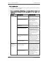
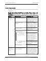
TS8000 Getting Started HA471056U001 Issue 2 © Copyright Parker SSD Drives 2008 All rights strictly reserved. No part of this document may be stored in a retrieval system, or transmitted in any form or by any means to persons not employed by a Parker SSD Drives company without written permission from Parker SSD Drives. Although every effort has been taken to ensure the accuracy of this document it may be necessary, without notice, to make amendments or correct omissions. Parker SSD Drives cannot accept responsibility for damage, injury, or expenses resulting there from. Companies, names and data used as examples herein are fictitious unless otherwise stated. All trademarks and copyrights are acknowledged as the property of their respective owners. Table Of Contents TS8000 Getting Started Table of Contents Product Overview ............................................................................................ 3 General Description ....................................................................................... 3 Safety Information .......................................................................................... 4 Contents Of Package ..................................................................................... 4 Specifications .................................................................................................. 4 Power Requirements ....................................................................................... 4 Battery .......................................................................................................... 5 LCD Module Display ...................................................................................... 5 Keypad ......................................................................................................... 5 Touchscreen .................................................................................................. 5 Memory ........................................................................................................ 5 Communications ........................................................................................... 6 Environmental Conditions ............................................................................... 6 Certifications And Compliances....................................................................... 6 Construction .................................................................................................. 7 Mounting Requirements .................................................................................. 7 Weight .......................................................................................................... 7 Dimensions ................................................................................................... 7 Installation And Power ...................................................................................... 8 Mounting Instructions .................................................................................... 8 Connecting To Ground .................................................................................. 8 Power Supply Requirements ........................................................................... 9 Software and Driver Installation.............................................................................10 Communications............................................................................................ 11 Configuring a TS8000 .................................................................................. 11 Cables And Drivers ...................................................................................... 11 The CompactFlash Card ............................................................................... 11 Ethernet Communications ............................................................................. 11 RS-232 Communications .............................................................................. 12 RS-422/485 Communications ....................................................................... 13 Software / Unit Operations ............................................................................. 14 DSI8000 Software ........................................................................................ 14 Keypad Buttons ............................................................................................ 14 Front Panel LEDs .......................................................................................... 14 Display ....................................................................................................... 14 Touchscreen ................................................................................................ 15 Troubleshooting The TS8000 ........................................................................ 15 Battery And Time Keeping ............................................................................. 15 Options And Accessories................................................................................. 17 Issue 2.00 Page i Table of Contents TS8000 Getting Started CompactFlash Socket ................................................................................... 17 Optional Communications Cards .................................................................. 17 Appendix A – TS8003 Specifications .................................................................. 18 TS8003 Dimensions ..................................................................................... 18 TS8003 Mounting Specifications .................................................................... 18 TS8003 Port Pin-Outs ................................................................................... 19 Appendix B – TS8006 Specifications ................................................................. 20 TS8006 Dimensions ..................................................................................... 20 TS8006 Mounting Specifications .................................................................... 20 TS8006 Port Pin-Outs ................................................................................... 21 Appendix C – TS8008 Specifications................................................................. 22 TS8008 Dimensions ..................................................................................... 22 TS8008 Mounting Specifications .................................................................... 22 TS8008 Port Pin-Outs ................................................................................... 23 Appendix D – TS8010 Specifications................................................................. 24 TS8010 Dimensions ..................................................................................... 24 TS8010 Mounting Specifications .................................................................... 24 TS8010 Port Pin-Outs ................................................................................... 25 Appendix E – TS8015 Specifications ……………………………………………….....26 TS8015 Dimensions .......................................................................................26 TS8015 Mounting Specifications......................................................................26 TS8015 Port Pin-Outs .....................................................................................27 Appendix F – TS8000 Troubleshooting ………………………………………………... 28 TS8000 General ............................................................................................28 TS8000 Messages ..........................................................................................31 TS8000 Serial Communications ......................................................................32 TS8000 Ethernet Communications...................................................................33 TS8000 Web Server.........................................................................................35 Page ii http://www.SSDdrives.com Product Overview TS8000 Getting Started Product Overview • Configured with DSI8000 software. • 3 onboard RS-232/422/485 comms ports. • Onboard 10/100 Base-T Ethernet for device comms, web hosting, and unit networking. • USB Port to download configuration files or transfer data from the unit. • 4 Mb (TS8003, TS8006), 8 Mb (TS8008, TS8010), or 32 Mb (TS8015) onboard flash memory (expandable with optional CompactFlash card). • 3.2 inch LCD display (TS8003) 128x64x2 color. • 5.7 inch STN display (TS8006) 320x240x256 color. • 7.7 inch DSTN display (TS8008) 640x480x256 color. • 10.4 inch TFT display (TS8010) 640x480x256 color. • 15 inch TFT display (TS8015) 1024x768x32K color. • 32 (TS8003), 5 (TS8006), 7 (TS8008), 8 (TS8010), or 10 (TS8015) button keypads for on screen menus. • 24vdc power supply (+/- 20%). • Resistive Analog Touchscreen (TS8006, TS8008, TS8010, TS8015). General Description The TS8000 Operator Interfaces combine unique capabilities normally expected from high-end units with a very affordable price. They are built around a high performance core with integrated functionality. This core allows the TS8000 series to leverage many of the features typically found in many PC based SCADA systems. The TS8000 series are able to communicate with many different types of hardware using high-speed RS-232/422/485 and 10/100 Base-T Ethernet communications ports. In addition, the TS8000’s feature a USB port for fast download of configuration files and access to trending and data logging. A CompactFlash socket is provided so that CF cards can be used to collect your trends and data logs as well as to increase the memory available for configuration files. In addition to accessing and controlling of external resources, the TS8000 series allows a user to easily view and enter information. Users can enter data through the touchscreen or front panel keypad. Page 3 http://www.SSDdrives.com Product Overview TS8000 Getting Started Safety Information All safety related regulations, local codes and instructions that appear in the manual or on equipment must be observed to ensure personal safety and to prevent damage to either the instrument or equipment connected to it. If equipment is used in a manner not specified by the manufacturer, the protection provided by the equipment may be impaired. Do not use the controller to directly command motors, valves, or other process actuators not equipped with safeguards. To do so can be potentially harmful to persons or equipment in the event of a fault to the controller. Contents Of Package The TS8000 unit will come shipped with the following additional equipment: • TS8000 Operator Interface terminal (TS8003/00/00, TS8006/00/00, TS8008/00/00, TS8010/00/00, or TS8015/00/00). • 2 meter USB programming cable (CM471053). • 5 meter serial communications cable (CM471054). • DSI8000 software CD with Value Added Apps (RI471055). • Getting Started bulletin (HA471056U000). • Panel cutout template. • Panel mounting hardware packet. • Panel mounting gasket. • Power supply terminal block. Specifications The following specifications pertain to the TS8000 series HMI. SSD Drives retains the right to modify specifications at any time, without prior notice. Power Requirements +24vdc (+/- 20%) @ 9.5W max (TS8003), 14W max (TS8006), 24W max (TS8008), 33W max (TS8010), 67W max (TS8015) - must use Class 2 or SELV rated power supply. Power connection is available via removable 3-position terminal block. Note: The TS8000’s “common” is not connected to the unit’s chassis. Refer to “Connecting To Ground” in the “Installation And Power” section of this document. Page 4 http://www.SSDdrives.com Specifications TS8000 Getting Started Battery Lithium CR2025 “button” cell. Typical lifetime of 10 years. LCD Module Display Model TS8003 TS8006 TS8008 TS8010 TS8015 Size 3.2 inch 5.7 inch 7.7 inch 10.4 inch 15.0 inch Type FSTN STN DSTN TFT TFT Colors 2 w. Backlight 256 QVGA 256 VGA 256 VGA 32,000 XGA Pixels 128 x 64 320 x 240 640 x 480 640 x 480 1024 x 768 Brightness --- 165 cd/m2 120 cd/m2 350 cd/m2 600 cd/m2 Backlight * --- 20,000 Hour typ. 40,000 Hour typ. 50,000 Hour typ. 50,000 Hour typ. * Lifetime at room temperature. Keypad TS8003: 8 user legendable keys, 5 navigation keys, 12 numeric keys, 4 dedicated keys, and 3 soft keys. TS8006: 5 keys for on-screen menus. TS8008: 7 keys for on-screen menus. TS8010: 8 keys for on-screen menus. TS8015: 10 keys for on-screen menus. Touchscreen Resistive Analog Type (TS8006, TS8008, TS8010, TS8015). Memory User: 4Mb (TS8003, TS8006), 8Mb (TS8008, TS8010), or 32Mb (TS8015) onboard nonvolatile flash memory. Memory Card: CompactFlash Type II slot for Type I and Type II CF cards. See section on Options and Accessories for more details. Page 5 http://www.SSDdrives.com Specifications TS8000 Getting Started Communications USB Port: Adheres to USB 1.1 specification. Device only using Type B connection. Serial Ports: Format and baud rates are individually programmable up to 115.2kb. • PGM Port: RS-232 port via RJ-12. • COMMS Ports: RS-232 port via RJ-12. RS-422/485 port via RJ-45. • DH485 TxEn: Transmit Enable; open collector, Voh = 15vdc, Vol = 0.5vdc @ 25mA max). Ethernet Port: 10/100 Base-T. RJ-45 jack is wired as a NIC. Environmental Conditions Operating Temperature Range: 0 to 50 deg C. Storage Temperature Range: -20 to 70 deg C. (TS8003, TS8006, TS8015) or 80 deg C. (TS8008, TS8010) Operating and Storage Humidity: 80% maximum relative humidity (non-condensing) from 0 to 50 deg C. Altitude: Up to 2000 meters. Certifications And Compliances Safety: IEC 1010-1, EN 61010-1: Safety requirements for electrical equipment for measurement, control, and laboratory use, Part 1. IP66 enclosure rating (face only), IEC 529. Type 4X enclosure rating (face only), UL50. Electromagnetic Compatibility: Emissions and immunity to EN 61326: Electrical equipment for measurement, control, and laboratory use, Part 1. Immunity to industrial locations: Electrostatic discharge EN 61000-4-2 Criterion A 4 kV contact xchrg, 8 kV air xchrg Electromagnetic RF fields EN 61000-4-3 Criterion B 10 V/m Fast transients (burst) EN 61000-4-4 Criterion B 2 kV power, 2 kv signal Surge EN 61000-4-5 Criterion A 1 kV L-L, 2 kV L&N-E power Page 6 http://www.SSDdrives.com Specifications TS8000 Getting Started RF conducted interference EN 61000-4-6 Criterion B 3 V/rms Emissions: Emissions EN 55011 Class A Notes: Criterion A (normal operation within specified limits), Criterion B (temporary loss of performance from which the unit self recovers). Construction Steel rear metal enclosure with NEMA 4X/IP66 aluminum front plate when correctly fitted with the provided gasket. Installation Category II, Pollution Degree 2. Mounting Requirements Maximum panel thickness is 0.25 inch (6.3 mm). For NEMA 4X / IP66 sealing, a steel panel with a minimum thickness of 0.125 inch (3.17 mm) is recommended. Maximum Mounting Stud Torque: 17 inch-pounds (1.92 N-m). Weight TS8003: 1.96 lbs (0.89 kg). TS8006: 3.00 lbs (1.36 kg). TS8008: 3.84 lbs (1.74 kg). TS8010: 5.53 lbs (2.51 kg). TS8015: 11.41 lbs (5.17 kg) Dimensions Refer to “Appendix A, B, C, D, and E - Dimensions” for individual unit dimensions. Page 7 http://www.SSDdrives.com Installation And Power TS8000 Getting Started Installation And Power The following specifications pertain to the TS8000 series HMI. SSD Drives retains the right to modify specifications at any time, without prior notice. Mounting Instructions This operator interface is designed for through-panel mounting. A panel cutout diagram and a template are provided. Care should be taken to remove any loose material from the mounting cut-out to prevent it from falling into the operator interface during installation. A gasket is provided to enable sealing to NEMA 4X/IP66 specifications. Install the provided nuts and tighten evenly for uniform gasket compression. For more Detailed documentation, refer to “Appendix A, B, C, D, and E – Mounting Templates”. Connecting To Ground This protective conductor terminal is bonded to conductive parts of the equipment for safety purposes and must be connected to an external protective grounding system. Each TS8000 has a chassis ground terminal on the back of the unit. The unit should be connected to ground. The chassis ground is not connected to the signal common of the unit. Maintaining isolation between the ground and the signal common is not required to operate the unit, however, other equipment connected to this unit may require isolation between the ground and the signal common. To maintain isolation between signal common and ground, care must be taken when connections are made to the unit. For example, a power supply with isolation between its signal common and ground must be used. Also, plugging in a USB cable may connect signal common to ground. TS8000 Ground Connection Important: Do not connect the power supply common to ground. The TS8000 has its own chassis ground that should be utilized. To further reduce electrical noise, SSD Drives also recommends the use of a ferrite core on the 24Vdc and 0Vdc leads between the power supply and the TS8000. Page 8 http://www.SSDdrives.com Installation And Power TS8000 Getting Started Power Supply Requirements The TS8000 series requires a 24vdc power supply, rated at 9.5W (TS8003), 14W (TS8006), 24W (TS8008), 33W (TS8010) or 67W (TS8015). The units may draw considerably less than the rated power depending upon the options being used. As additional features are used, the unit will draw increasing amounts of power. Items that could cause increases are: additional communications, optional communications cards, use of the CompactFlash card, and other features programmed through DSI8000. In any case, it is very important that the power supply is mounted correctly if the unit is to operate reliably. Please take care to observe the following points: Page 9 • The power supply must be mounted close to the unit, with usually not more than 6 feet (1.8 m) of cable between the supply and the operator interface. Ideally, the shortest length possible should be used. • The wire used to connect the operator interface’s power supply should be at least 22 gauge wire. If a longer cable run is used, a heavier gauge wire should be used. The routing of the cable should be kept away from large contactors, inverters, and other devices which may generate significant electrical noise. • A power supply with a Class 2 or SELV rating should be used. A Class 2 or SELV power supply provides isolation to accessible circuits from hazardous voltage levels generated by a mains power supply due to single faults. SELV is an acronym for “safety extra-low voltage.” SELV circuits exhibit voltage that are safe to touch both under normal operating conditions and after a single fault, such as a breakdown of a layer of basic insulation or after the failure of a single component has occurred. http://www.SSDdrives.com Communications TS8000 Getting Started Software and Driver Installation Please read the following instructions before connecting the TS8000 to your PC! It is important that you follow these instructions carefully or you may have to repeat the installation once more. Install the DSI8000 software. 1. Insert the DSI8000 CD-ROM into the disk drive of the computer. 2. Installation should start after a few seconds. If no instructions appear, you may have autorun disabled. If this is the case, select the Run option from the Start menu and enter x:\setup, where x is the drive letter of your CD-ROM drive. 3. After the Install Shield window appears click Next >. You will then be prompted to enter the User Name, Company Name, and Destination Folder. Click Next >. 4. Install Shield should finish loading the DSI8000 software and when finished you will be prompted to click Finish. 5. After installing the software it is recommended that you click Help in the quick access toolbar then click Check for Updates. This will verify you have the latest version of DSI8000. Install the TS8000 HMI USB drivers. 1. Connect the TS8000 to your PC using the USB cable provided and then apply power to it. Windows will launch the Found New Hardware Wizard. 2. The wizard may prompt you to locate updated device drivers. If prompted, select No, not at this time, and then click Next >. 3. The wizard will then ask you for install options. Choose Install from a list or specific location and then click Next >. 4. Make sure that Search for the best driver in these locations option is selected as well as Include this location in the search. In the navigation window, browse to C:\Program Files\SSD Drives\DSI8000\Device, then click Next >. It is important that you perform this step correctly, or you may have to manually remove the drivers using Windows Device Manager, and repeat the installation once more. Note that the TS8000 USB drivers have not been digitally signed by Microsoft. If prompted, click Continue Anyway to complete the installation process. 5. When the driver installation is complete click Finish. Note: If you have trouble accessing the TS8000 via USB communications, Windows Device Manager may give you valuable information as to the error. To access Windows Device Manager, right-click My Computer on the Windows Desktop. Select Properties in the drop-down list. Navigate to the Hardware tab. Click the Device Manager button. Expand the Universal Serial Bus controllers tree. The TS8000 installs itself as both HMI Loader and HMI, depending on the stage of installation. Page 10 http://www.SSDdrives.com Communications TS8000 Getting Started Communications The following specifications pertain to the TS8000 series HMI. SSD Drives retains the right to modify specifications at any time, without prior notice. Configuring a TS8000 The TS8000 series are configured using DSI8000 software. DSI is included in the software CD that comes packaged with each unit, or is also available from SSD Drives. Updates to DSI8000 are posted on the SSD Drives website as they are made available. By configuring the TS8000 using the latest version of DSI8000, you are assured that the unit has the most up-to-date feature set. DSI software can configure the TS8000 through the RS-232 PGM port, USB port, Ethernet Port, or the CompactFlash socket. Cables And Drivers The USB port is connected using a standard USB cable with a Type B connector. The driver needed to allow your PC to access the USB port will be installed along with the DSI8000 software. If this driver has not been installed, it can be downloaded from the website. The RS-232 PGM port uses a specialized cable to connect to the serial port of your PC. If you choose to make this cable, refer to “Appendix A, B, C, D, and E - Port Pin-Outs” section of this document for wiring information. The CompactFlash Card The CompactFlash card can also be used to program a TS8000 by placing a configuration file and firmware on the CompactFlash card. The card is then inserted into the target TS8000 and the unit is then powered on. Refer to the “DSI8000 User Manual” (HA471055U001) for more information on this operation. In order to transfer data from the CompactFlash card via the USB port, a driver must be installed on your computer. This driver is installed with DSI8000 and is located in the folder: C:\Program Files\SSD Drives\DSI8000\Device\. This may have already been accomplished if the TS8000 was configured using the USB port. Refer to the "Options and Accessories" section of this document for technical specifications on the CompactFlash Card. Ethernet Communications Ethernet communications can be established at either 10 Base-T or 100 Base-T speeds. The TS8000 unit’s RJ-45 jack is wired as a true NIC (network interface card). For example, when wiring to a hub or switch, use a straight-thru cable. When wiring to another NIC, however, a cross-over cable must be used. The Ethernet connector contains two LED’s. A yellow LED in the upper right corner, and a bi-color (green / amber) LED in the upper left corner. The LED’s represent the following status conditions: Page 11 http://www.SSDdrives.com Communications TS8000 Getting Started LED Color Yellow (solid) Yellow (flashing) Description Link established Data transfer active Green 10 Base-T communications Amber 100 Base-T communications Refer to the “DSI8000 User Manual” (HA471055U001) for additional information on Ethernet communications. RS-232 Communications The TS8000 unit has two RS-232 ports: the PGM port, and the COMMS port. Although only one of these ports can be used for programming, both ports can be used for remote device communication. The RS-232 PGM port can be used for either master or slave protocols with any TS8000 configuration. Examples of RS-232 communications could involve another SSD Drives product, a PLC, or a PC computer. By using a cable with RJ-12 ends on it, and a roll between Tx and Rx wires, RS-232 communications with another TS8000 series touchscreen can be established. For RS-232 cable wiring between a TS8000 and a PC, refer to the following table: RS-232 TS8000 To PC Connections TS8010: RJ-12 Name PC: DB-9 4 COM 1 5 Tx 2 2 Rx 3 n/c 4 3 COM 5 n/c 6 1 CTS 7 6 RTS 8 n/c 9 Page 12 Name DCD Rx Tx DTR GND DSR RTS CTS RI http://www.SSDdrives.com Communications TS8000 Getting Started RS-422/485 Communications The TS8000 has one or more RS-422/485 port, depending on the model. This port can be configured to either RS-422 or RS-485, depending upon the user’s needs. Page 13 http://www.SSDdrives.com Software / Unit Operations TS8000 Getting Started Software / Unit Operations The following specifications pertain to the TS8000 series HMI. SSD Drives retains the right to modify specifications at any time, without prior notice. DSI8000 Software DSI8000 software is included with each purchase of a TS8000 unit, or it is also available from SSD Drives. The latest updates to the software are always available from the SSD Drives website at www.ssddrives.com/usa under Resource Center/Software Downloads. Keypad Buttons The TS8003 keypad consist of five unique key types: eight legendable keys, 5 navigational keys, a 12 key numeric keypad, three soft keys for on screen menu selections, and four keys labeled ALARMS, MUTE, EXIT, and MENU. The TS8006 keypad consist of five userassignable keys for on-screen menus. The TS8008 keypad consist of seven user-assignable keys for on-screen menus. The TS8010 keypad consist of eight user-assignable keys for on-screen menus.The TS8015 keypad consist of ten user-assignable keys for on-screen menus. Front Panel LEDs There are three front panel LEDs. Shown below is the default status of each of the LEDs: LED Indication Red LED - Power Flashing Unit is in the boot loader, no valid configuration is present. Steady Unit is powered and running an application. Yellow LED – CF Card Off No CompactFlash card is present. Steady A valid CompactFlash card is present. Flashing Rapidly Unit is checking the CompactFlash card. Flickering Unit is writing to the CompactFlash card. Flashing Slowly An incorrectly formatted CompactFlash card is present. Green LED - Alarm Flashing A tag is in an alarm state. Steady Valid configuration loaded and no alarms are present Display The TS8006, TS8008, TS8010 and TS8015 use a liquid crystal display (LCD) for displaying text and graphics. The display utilizes a cold cathode fluorescent tube (CCFL) for lighting the display. The CCFL tubes can be dimmed for low light conditions. Page 14 http://www.SSDdrives.com Software / Unit Operations TS8000 Getting Started These CCFL tubes have a limited lifetime. Backlight lifetime is based upon the amount of time the display is turned on at full intensity. Turning the backlight off when the display is not in use can extend the lifetime of your backlight. This can be accomplished through the DSI8000 software when configuring your unit. Touchscreen The TS8006, TS8008, TS8010 and TS8015 utilize a resistive analog touchscreen for user input. The unit will only produce an audible tone (beep) when a touch on an active touchscreen cell in sensed. The touchscreen is fully functional as soon as the operator interface is initialized, and can be operated with gloved hands. Troubleshooting the TS8000 If for any reason you have trouble operating, connecting, or simply have questions concerning your new TS8000, refer to Appendix F for troubleshooting tips. Battery and Time Keeping A battery is used to keep time when the unit is without power. Typical accuracy of the TS8000 time keeping is less than one minute per month drift. The state of the battery does not in any way affect the unit’s program memory. All configurations are stored in nonvolatile flash memory. Caution – Risk Of Electric Shock: The inverter board, attached to the mounting plate, supplies the high voltage necessary to operate the backlight. Touching the inverter board may result in injury. Please exercise caution while working inside of the unit. Caution: The circuit board contains static sensitive components. Before handling the operator interface without the rear cover attached, discharge static charges from your body by touching a grounded bare metal object. Ideally, handle the operator interface at a static controlled, clean workstation. Do not touch the surface areas of the circuit board. Dirt, oil, or other contaminants may adversely affect circuit operation. To change the battery of a TS8000, remove all power and other cabling from the unit. Next, take off the unit’s rear cover by removing the five screws designated by the arrows on the rear of the unit. Then, by lifting the top side, hinge the rear cover, thus providing clearance for the connectors on the bottom side of the PCB as shown in the illustration below. Remove the old battery from the holder and replace with a new one. The battery used is a CR2025 lithium button cell. Assemble in the reverse order. The following example depicts the battery replacement procedure for a TS8010. Page 15 http://www.SSDdrives.com Software / Unit Operations Page 16 TS8000 Getting Started http://www.SSDdrives.com Options And Accessories TS8000 Getting Started Options And Accessories The following specifications pertain to the TS8000 series HMI. SSD Drives retains the right to modify specifications at any time, without prior notice. CompactFlash Socket The TS8000 is equipped with a Type II CompactFlash socket. This socket will accept either Type I or Type II cards. Make sure to use cards with a minimum of 4Mb and a maximum of 2 Gb capacity. Cards can be obtained at most computer and office supply retailers. CompactFlash cards can be used for: configuration transfers, storage of larger configurations, data logging, and trend storage. Note: Do not remove or insert the CompactFlash card while power is applied to the unit. Refer to the “Front Panel LEDs” section of this document for more information. Information stored on a CompactFlash card can be read by a card reader attached to a PC. This information is stored in a Windows compatible FAT-16 file format. NOTE: For reliable operation of the product, SSD Drives recommends the use of SanDisk and SimpleTech brands of CompactFlash cards. Optional Communications Cards A communication card socket is provided for future communications cards. Visit the SSD Drives website for information and availability of these cards. Page 17 http://www.SSDdrives.com Appendix A – TS8003 Specifications TS8000 Getting Started Appendix A – TS8003 Specifications The following specifications pertain to the TS8003 series HMI. SSD Drives retains the right to modify specifications at any time, without prior notice. TS8003 Dimensions TS8003 Mounting Specifications Page 18 http://www.SSDdrives.com Appendix A – TS8003 Specifications TS8000 Getting Started TS8003 Port Pin-Outs Page 19 http://www.SSDdrives.com Appendix B – TS8006 Specifications TS8000 Getting Started Appendix B – TS8006 Specifications The following specifications pertain to the TS8006 series HMI. SSD Drives retains the right to modify specifications at any time, without prior notice. TS8006 Dimensions TS8006 Mounting Specifications Page 20 http://www.SSDdrives.com Appendix B – TS8006 Specifications TS8000 Getting Started TS8006 Port Pin-Outs Page 21 http://www.SSDdrives.com Appendix C – TS8008 Specifications TS8000 Getting Started Appendix C – TS8008 Specifications The following specifications pertain to the TS8008 series HMI. SSD Drives retains the right to modify specifications at any time, without prior notice. TS8008 Dimensions TS8008 Mounting Specifications Page 22 http://www.SSDdrives.com Appendix C – TS8008 Specifications TS8000 Getting Started TS8008 Port Pin-Outs Page 23 http://www.SSDdrives.com Appendix D – TS8010 Specifications TS8000 Getting Started Appendix D – TS8010 Specifications The following specifications pertain to the TS8010 series HMI. SSD Drives retains the right to modify specifications at any time, without prior notice. TS8010 Dimensions TS8010 Mounting Specifications Page 24 http://www.SSDdrives.com Appendix D – TS8010 Specifications TS8000 Getting Started TS8010 Port Pin-Outs Page25 http://www.SSDdrives.com Appendix E – TS8015 Specifications TS8000 Getting Started Appendix E – TS8015 Specifications The following specifications pertain to the TS8015 series HMI. SSD Drives retains the right to modify specifications at any time, without prior notice. TS8015 Dimensions TS8015 Mounting Specifications Page 26 http://www.SSDdrives.com Appendix E – TS8015 Specifications TS8000 Getting Started TS8015 Port Pin-Outs Limited Warranty SSD Drives warrants the goods against defects in design, materials, and workmanship for the period of 12 months from the date of delivery on the terms detailed in SSD Drives Standard Conditions of Sale IA058393C. SSD Drives reserves the right to change the content and product specification without notice. Page 27 http://www.SSDdrives.com Appendix F – TS8000 Troubleshooting TS8000 Getting Started Troubleshooting the TS8000 This section covers the most common problems encountered while setting up, programming or using the product. Do not forget to always download in the device after changing settings in DSI8000. GENERAL PROBLEM POSSIBLE CAUSES POSSIBLE SOLUTIONS No power applied to the unit. Check power supply. Units require Unit screen is blank. And PWR LED off. 24 VDC, ± 10%. And PWR LED on. Contrast too low. Program one of the soft keys with the action as User Defined and the following code in the field On Pressed: dispcontrast++ No primitives on the display. Add objects to the User Interface in DSI8000. Backlight is off. Push one of the soft keys to turn it back on. Backlight tube is broken. Replace the backlight tube. Unit continually Cross-references between tags, Remove one of the references or cycles on and off. e.g., Var1 uses Var2 as maximum use formula tags for indirect which in turn uses Var1 as reference, e.g., Form1 is equal to minimum. Var1 and used in Var2 minimum instead of Var1. Database is corrupted. Create a new database or send to technical support for debugging. Unit cycles power Most likely a program going in an Check if the operation launches after an operation. endless loop. program containing loops with no exit point. Touchscreen not The touchscreen is not calibrated Use the Touch Calibration primitive to accurate correctly. recalibrate. Primitive available under Insert > System > Touch Calib. Insert the primitive so it covers the entire screen. CF LED flashing slowly. CF card corrupted or invalid. Format the card from DSI8000 using the Link > Format Flash menu. Page 28 http://www.SSDdrives.com Appendix F – TS8000 Troubleshooting TS8000 Getting Started PROBLEM POSSIBLE CAUSES POSSIBLE SOLUTIONS Unit shows “Version The database currently in the device Download the database from Mismatch”. does not match DSI8000’s firmware DSI8000 again. version. (Message occurs after a download with a new version of DSI8000 interrupted before the database was downloaded.) Unit shows “Invalid The database in the device is Download a database from Database”. corrupted or there are no databases DSI8000. in the device. No communication with target See Serial Communication or device Ethernet Communication. Value does not The tag on the screen is not linked Check the tag mapping making update. correctly. sure the target device (PLC, etc.) Values show “----” register is correct. Check the primitive Data Source in the user interface in case the word WAS is displayed. Re-link the tag in this case. Value shows +BIG Not enough digits before the Increase the number of digits or –BIG. decimal point to show the number. before the decimal point in the tag For example, data is 1000.5 and format. format is three digits before the decimal point and one after. Value deviates by a The tag format is not correct. Value is invalid. Change the decimal point position in the tag format. factor of ten. Incorrect tag type. Check if the tag type corresponds to the data type. Is the data a floating point number and thus the tag a real (Pi symbol), and not an integer (X symbol)? Incorrect data mapping. Check if the tag is accessing the correct target device register. Incorrect primitive on the display. Check if the primitive corresponds to the tag type. For example, primitive is a Text Integer so the tag has to be an integer. Page 29 Data received is not what’s Use the transform property on the expected. For example, bytes tag to modify the data source. You reversed in might have to try multiple solutions the word. to solve the issue. http://www.SSDdrives.com Appendix F – TS8000 Troubleshooting TS8000 Getting Started PROBLEM POSSIBLE CAUSES POSSIBLE SOLUTIONS Symbol or image The background of the image is not Change the primitive Fill Format to leaves a trace when refreshed. Solid color. animated. Add the system variable dispcount in the background of the image to force the refresh. Rich Bar Graph or Tag minimum and maximum are Check the tag’s minimum and Dial Gauge does not setup. maximum values. These are used not move by both primitives for min and max. Trend Viewer curve No minimum and maximum setup Check that all displayed tags in the stuck at the bottom. on the data tags displayed in the trend viewer have a Minimum and viewer. a Maximum setup. Program issue See program troubleshooting. Location of the drivers unknown. The drivers are located under Display shows “TIMEOUT” or “NOT READY” or “WORKING”. USB Drivers location for DSI8000\Device installation folder. Windows. For example C:\Program Files\SSD Drives\DSI8000\Device. USB Driver The operating system is unable to In your operating system device installation. find the driver or the installation manager, check if the device failed. TS8000 HMI is present. If so, uninstall that device. Follow the USB installation guide in this manual. Upgrading The option selected during the Launch the upgrade again and DSI8000 did not upgrade was Modify instead of choose Repair when prompted. upgrade the Repair. software version. Page 30 http://www.SSDdrives.com Appendix F – TS8000 Troubleshooting TS8000 Getting Started DSI8000 MESSAGES ERRORS POSSIBLE CAUSES POSSIBLE SOLUTIONS Device The device you are trying to Create a new database file incompatible with download into doesn’t match the corresponding to your device file. database device. (File > New). Unable to open The communication port you try to communication download with is unavailable. port. Cable not connected Check if the cable is connected correctly to the PC and the device programming ports (USB or PG Port). Incorrect download Check that DSI8000 is directed to communication port the correct communication port (Link > Options). Port already used Check that the communication port is not used by another service or software especially for serial ports. Target device IP If you download via Ethernet, address incorrect Check the IP address of the target device in Link > Options. No USB Drivers Check that the USB drivers were install successfully. Reinstall TS8000 HMI USB driver under the PC device manager if necessary. No Reply from Cable is not connected Make sure the cable is connected or check above solutions terminal If the message appears while Download again with Link > downloading to the device Update or F9 CompactFlash The version of DSI8000 on the PC is Insert a CompactFlash Card in the required for different from the target device target device. upgrade. firmware version when attempting a download via Ethernet. Use another communication port for download; USB or Serial. The window is too The current User interface view is Change the panel view using View small to allow too small to allow editing. > Panel > Display only. The device returned The device you are trying to Update DSI8000 to the latest an unexpected reply download to is not supported by version available on code. this version of DSI8000. www.SSDDrives.com editing. Choose Repair when upgrading. Page 31 http://www.SSDdrives.com Appendix F – TS8000 Troubleshooting TS8000 Getting Started SERIAL COMMUNICATION This section is used to troubleshoot the communication between two devices linked via serial ports, i.e. RS232 or RS485. TIP: For communication troubleshooting, it is strongly advised to create a new DSI8000 database including only one data tag mapped to a known register in the target device. PROBLEM POSSIBLE CAUSES POSSIBLE SOLUTIONS Values show “----” Port settings do not match. Check that the port settings of the DSI8000 device match the target device (i.e. Baud, Parity, etc.). Incorrect target device address. Check that the target device address in DSI8000 (in communications on the PLC symbol) matches the target device address setup. Incorrect cable Check the cable part number or cabling to match your protocol. Incorrect communication port Check if the cable is connected to the right communication port. If the above is correct, check that the protocol settings are on the right communication port in DSI8000. Communication port connector pins Although unlikely, check the bent inward. communication port connector pins on the SSD Drives device in case some are bent inward resulting in a bad contact with the cable. Incorrect tag mapping Check that the tag is mapped to an existing register in the target device. Values blink Incorrect tag mapping on one of Delete tags one after another and between the data the tags on the display. download in-between. When the and “----” values on the screen stop blinking, the last deleted tag was mapped incorrectly or accessed an unknown register in the target device. Communications times-out. Increase the Slave Response or Device Timeout on the communication port or target device in DSI8000. Page 32 http://www.SSDdrives.com Appendix F – TS8000 Troubleshooting TS8000 Getting Started ETHERNET COMMUNICATION This section is used to troubleshoot the communication between two devices linked via Ethernet. TIP: For communication troubleshooting, it is strongly advised to create a new DSI8000 database including only one data tag mapped to a known register in the target device. PROBLEM POSSIBLE CAUSES POSSIBLE SOLUTIONS Values show “----” Incorrect target device IP address. Check the target device IP address in DSI8000 (in communications on the PLC symbol) to match the target device IP address setup. Incorrect cable or wrong Check the LED on the DSI8000 connection. device Ethernet port. If none are lit, there are no connections. Check the cable or that the Ethernet port is enabled in DSI8000, see below. Ethernet port disabled. Check that the Ethernet port in DSI8000 is enabled. DSI8000 and target devices are in a different address domain. If no routers are present on the network. Check that the target device IP address and DSI8000 device IP address are different but in the same domain. (For example, both start with the same three first numbers; ex: 192.168.2.xxx if the mask is 255.255.255.0). If a router is present on the network. Check the DSI8000 device Ethernet port gateway address to match the router IP address. Incorrect tag mapping. Check that the tag is mapped to an existing register in the target device. Values blink Incorrect tag mapping on one of Delete tags one after another and between the data the tags on the display. download in-between. When the and “----” values on the screen stop blinking, the last deleted tag was mapped incorrectly or accessed an unknown register in the target device. Page 33 http://www.SSDdrives.com Appendix F – TS8000 Troubleshooting Communications times-out. TS8000 Getting Started Increase the Slave Response or Device Timeout on the communication port or target device in DSI8000. PROGRAMS PROBLEM POSSIBLE CAUSES POSSIBLE SOLUTIONS The program does Program not launched. Check if the program is called not seem to run. somewhere in the database (code: ProgramName()). Some conditions in the program are If the DSI8000 device has a beeper, not met (if, switch or loops). use the beep() function in the program to check if the program does go through the condition. Otherwise, use a dummy tag and change its value at different places in the program to check where it stops. Display shows Program is launched but data are If the message disappears, the “NOT READY” not available to run it yet. program was launched successfully however it seems to require time to fetch all the required data. Communication is too slow or your database program is getting too complex. Display shows The device is busy working on a The program takes too much time “WORKING” program. to run. Either run it in the background or reduce the workload. If it times-out, the program was stuck in a loop. Page 34 Display shows Program was unable to run due to Make sure that all the tags in the “TIMEOUT” unavailable data. program exist in the target device. http://www.SSDdrives.com Appendix F – TS8000 Troubleshooting TS8000 Getting Started WEB SERVER PROBLEM Internet Browser POSSIBLE CAUSES SOLUTIONS Web Server not enabled. Check that the Web Server in DSI8000 is enabled. says “Cannot display the web page” Ethernet port disabled or Ethernet Check that the Ethernet port in settings issue. DSI8000 is enabled and has a correct IP address. See Ethernet Communication troubleshooting. Incorrect DSI8000 device IP Check that the IP address in the address. browser matches DSI8000’s Ethernet IP address. Incorrect PC IP Address. Check the PC Ethernet Settings for a valid IP address. Page 35 http://www.SSDdrives.com Sales Offices Australia Parker Hannifin Pty Ltd 9 Carrington Road Private Bag 4, Castle Hill NSW 1765 Tel: +61 2 9634 7777 Fax: +61 2 9899 6184 Belgium Parker Hannifin SA NV Parc Industriel Sud Zone 11 23, Rue du Bosquet Nivelles B -1400 Tel: +32 67 280 900 Fax: +32 67 280 999 Brazil Parker Hannifin Ind. e Com. Ltda. Av. Lucas Nogueira Garcez, 2181 Esperança - Caixa Postal 148 Tel: +55 0800 7275374 Fax: +55 12 3954 5262 China Parker Hannifin Motion & Control (Shanghai) Co. Ltd. - SSD Drives Suite B2109 21st Floor Hanwei Plaza 7 Guanghua Road Chaoyang District Beijing 100004 Tel: +86(10)6561 0520/1/2/3/4/5 Fax: +86(10)6561 1070 Canada Parker Motion and Control 160 Chisolm Drive Milton, Ontario L9T 3G9 Tel: +1(905)693 3000 Fax: +1(905)876 1958 France Parker SSD Parvex 8 Avenue du Lac B.P. 249 F-21007 Dijon Cedex Tel: +33 (0)3 80 42 41 40 Fax: +33 (0)3 80 42 41 23 Germany Parker Hannifin GmbH Von-Humboldt-Strasse 10 64646 Heppenheim Tel: +49(0)6252 798200 Fax: +49(0)6252 798205 India SSD Drives India Pvt Ltd 151 Developed Plots Estate Perungudi, Chennai, 600 O96 Tel: +91 44 43910700 Fax: +91 44 43910700 Italy Parker Hannifin SPA Via Gounod 1 20092 Cinisello Balsamo Milano Tel: +39 02 361081 Fax: +39 02 66012808 Singapore Parker Hannifin Singapore Pte Ltd 11, Fourth Chin Bee Rd Singapore 619702 Tel: +65 6887 6300 Fax: +65 6265 5125 Spain Parker Hannifin (Espana) S.A. Parque Industrial Las Monjas Calle de las Estaciones 8 28850 Torrejonde Ardoz Madrid Tel: +34 91 6757300 Fax: +34 91 6757711 Sweden Parker Hannifin AB Montörgatan 7 SE-302 60 Halmstad Tel: +46(35)177300 Fax: +46(35)108407 UK Parker Hannifin Ltd. Tachbrook Park Drive Tachbrook Park Warwick CV34 6TU Tel: +44(0)1926 317970 Fax: +44(0)1926 317980 www.SSDdrives.com HA471056U001 TS8000 Getting Started Parker Hannifin Corporation SSD Drives Division 9225 Forsyth Park Dr. Charlotte, NC 28273 Tel: +1 (704) 588-3246 Fax: +1 (704) 588-3249