1
US006774596B1
(12) United States Patent
Bisset
(54)
INDICATOR FOR A ROBOTIC MACHINE
(10) Patent N0.:
(45) Date of Patent:
(56)
References Cited
U.S. PATENT DOCUMENTS
(75) Inventor: David Lindsey Bisset, Wiltshire (GB)
(73) Assignee: Dyson Limited, Wiltshire (GB)
*
N ot1ce:
'
US 6,774,596 B1
Aug. 10, 2004
6,042,256 A
*
3/2000
6,157,143
*
12/2000
A
Gothard .................... .. 362/558
Bigio et al.
.......
. . . . . ..
315/307
6,296,367 B1 * 10/2001
Parsons et al. ........... .. 362/183
s u bj ect to an yd'1sc 1 a1mer,
'
t h e term 0 r t h'15
6,442,450
Inoue et al.
patent is extended or adjusted under 35
6,488,390 B1 * 12/2002
U.S.C. 154(b) by 0 days.
B1
*
8/2002
......
. . . . . ..
700/245
Lebens et al. ............ .. 362/231
* cited by examiner
(21) Appl. No.:
09/959,874
(22) PCT Filed:
May 22, 2000
Primary Examiner—Karen Masih
(74) Attorney, Agent, or Firm—Morrison & Foerster LLP
(86) PCT No.:
PCT/GB00/01971
(57)
§ 371 (6X1),
(2), (4) Date:
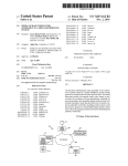
A robotic machine such as a robotic vacuum cleaner is
controlled to carry out a task of cleaning a room. The
Nov. 9, 2001
machine has a plurality of sensors including infrared
sensors, ultrasonic sensors and light sensors through Which
(87) PCT Pub. No.: WO00/73867
the machine can navigate its Way around a room Without
PCT Pub. Date: Dec. 7, 2000
(30)
hitting objects or Walls in its path. The machine has an
Foreign Application Priority Data
May 28, 1999
ABSTRACT
(GB) ........................................... .. 9912472
(51)
Int. Cl.7 ................................................. .. B25J 9/18
(52)
US. Cl. ........................... .. 318/568.11; 318/568.12;
indicator light Which changes color depending upon the state
of interaction of the various sensors With the environment,
indicating the ‘mood’ of the cleaner. The indicator may
include three primary color light sources Which are com
bined Within a re?ective frusto-conical chamber and a
translucent lens dome in order to combine the primary colors
318/568.2; 318/565
(58)
into a single colored light as vieWed by a user. This makes
the machine more user-friendly.
Field of Search ..................... .. 318/568.11, 568.12,
318/6582, 565, 568.1; 700/245, 248
28 Claims, 5 Drawing Sheets
U.S. Patent
Aug. 10, 2004
Sheet 1 0f 5
FIG.1.
US 6,774,596 B1
U.S. Patent
Aug. 10, 2004
Sheet 3 0f 5
US 6,774,596 B1
555
FIG.3A.
GREEN
CYAN
YELLOW
BLUE
RED
MAGENTA
F|G-4
U.S. Patent
Aug. 10, 2004
Sheet 4 0f 5
US 6,774,596 B1
COMMS
LINK
/“
2.:
25
F PGA
55
F|G.5.
MOOD UGHT
6O
us
SERVER
jg
--.1{
‘#5 w
m 1
WALL FOLLOW
'
-
TASK
DECISION 65
-—-—-———
?lm TASK
6)‘
62
CS
L-_____.[1§N|TOR
1Q.
:66 74
‘
I
FIG.6.
\
MOTOR
DRIVER
U.S. Patent
Aug. 10, 2004
Sheet 5 0f 5
lNDiCATOR
35
F|G.7A.
US 6,774,596 B1
ROBOT STATE
O
BLUE
FIGJB.
GREEN!
GREEN
BLUE
FIG.7C.
RED
r-a.“
FIGJD.
O
RED
FLASHING
=
#7:‘-
)
f
US 6,774,596 B1
1
2
INDICATOR FOR A ROBOTIC MACHINE
interaction betWeen the machine and the environment,
Wherein the controller is arranged to change the colour of the
light according to the state of interaction and Wherein the
indicator light comprises tWo or more differently coloured
light sources Which am separately energisable, and means
for combining the light output of the light sources to give the
effect of a single coloured light.
FIELD OF THE INVENTION
.
.
.
.
.
This invention relates to a robotic machine and to a
5
method of operating a robotic machine. It can be applied to
a robotic ?oor clearing device, such as a robotic vacuum
cleaner, or some other robotic machine.
BACKGROUND OF THE INVENTION
It is knoWn to provide a robotic vacuum cleaner pro
grammed to clean the ?oor of a room. The programming
may consist of feeding a detailed map of the room and
training the cleaner to reciprocate to and fro from one side
to the other side of the room. Alternatively, it may comprise
leading the cleaner around the room in a training cycle so
The light sources can be illuminated alone or in combi
10
indicator for an indication of the machine’s state or ‘mood’.
15
When only one of the light sources is energised the indicator
appears as that colour. For example, When the red source is
energised, the indicator appears red. When multiple light
that the cleaner repeats the cycle from information stored in
memory. International Patent Application No. PCT/GB99/
sources are energised at the same time, the outputs of the
sources are combined and the indicator has the color of the
combination For example, When the red and green sources
04072 describes an autonomous vacuum cleaner Which
performs a spira-like pattern to traverse the ?oor surface of
are illuminated, the indicator appears yelloW/orange. Small
variations in the state of the machine can be easily conveyed
by shifting the colour of the indicator, eg from green to
a room.
Some machines have Warning lights to alert the user When
a fault has occurred. For example, a vehicle engine man
agement system Will have a Warning light Which illuminates
nation.
By providing a single indicator Which can take a range of
colours, operation of the machine is made mom user
friendly. Rather than looking at a confusing aWay of
indicators, the user simply looks at the colour of the single
25
When a fault occurs. This Way be a minor fault Which does
green-blue.
Preferably the light sources comprise red, green and blue
primary colour light sources as this combination of light
sources is capable of generating the full range of visible
colours.
There can be multiple light sources of each colour. This
not have to be recti?ed urgently, or it may be a major fault
requiring urgent attention. Until the vehicle fault is diag
nosed by specialist equipment, or unless the vehicle breaks
doWn, the user Will be unaWare of the state of health of his
increases the light output and, by interleaving the sources
With other, differently-coloured sources, an improved blend
ing effect is achieved.
vehicle engine and its associated systems.
Domestic appliances such as Washing machines and dish
Washers have animated dials Which indicate What part of the
Washing cycle the machine has reached. It is also knoWn to
Each of the light sources can be provided as a separate
use a limited range of indicator lamps to represent a large 35 device, a plurality of such devices being mounted on a
support, or a single multi-source device can be provided.
number of fault conditions, With each fault condition being
The multi-source device can include some form of diffused
represented by a different combination of illuminated lights
lens or this can be provided separately.
or a combination of ?ashing and steady illumination of the
lamps. This can be very confusing for a user, and often
While the embodiment describes the use of the indicator
requires a user to consult a user manual to interpret the state 40 light on a robotic vacuum cleaner, the indicator can be used
of the machine.
on other forms of robotic machine.
Computers have programs Which, by making an unusual
sound, Wan the user that he is adopting an illegal or
Another aspect of the present invention provides a method
of operating a robotic machine.
inappropriate entry on the keyboard or that the computer
cannot execute the requested function. AWide choice of such
BRIEF DESCRIPTION OF THE DRAWINGS
sounds is commonly available.
The Sony Corporation, on 11 May 1999, announced the
launch of a four-legged entrainment robot called “AIBO”.
The head of the robot has tWo eyes, each eye having a red
LED lamp and a green LED lamp spaced apart from one
another. The red lamp is illuminated to express anger and the
green lamp is illuminated to express happiness. The eyes
?ash red and men When the robot is confused.
Some users feel uneasy about using modern appliances.
Embodiments of the invention Will noW be described With
reference to the accompanying draWings in Which:
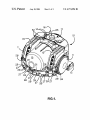
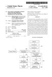
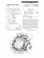
FIG. 1 is a perspective vieW of a robotic cleaning device
according to an embodiment of the invention;
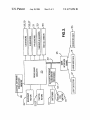
FIG. 2 is a schematic diagram of a poWer management
and navigation system of the device of FIG. 1;
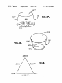
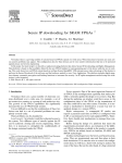
FIGS. 3A and 3B schematically shoW tWo feW of indicator
light used in the cleaning device of FIG. 1;
55
This is not helped by providing appliances that have a
complicated and confusing aWay of controls and indicator.
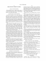
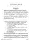
FIG. 4 shoWs Fe Well-knoWn colour triangle;
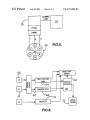
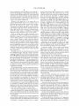
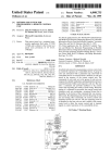
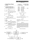
FIG. 5 shoWs the functional blocks Which control the
indicator light;
SUMMARY OF THE INVENTION
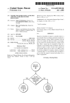
FIG. 6 schematically shoWs the softWare tasks performed
by the controller of the cleaning device; and
It is an object of the present invention to improve a user’s
understanding of the state of interaction occurring betWeen
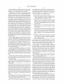
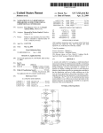
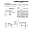
FIGS. 7A—7D shoW a range of states for the cleaner and
the corresponding condition of the indicator light.
a machine and its environment.
A ?rst aspect of the present invention provides a robotic
machine having a plurality of sensors by means of Which the
robotic machine can interact With its environment, a con
troller for controlling the machine to carry out a task using
the sensors, and an indicator light to indicate the state of
65
DETAILED DESCRIPTION OF THE
INVENTION
Referring to FIG. 1 of the draWings, ther is shoWn a
robotic ?oor cleaning device in the form of a vacuum
US 6,774,596 B1
3
4
cleaner, comprising a main body 10, tWo drive Wheels 11, a
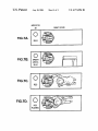
blue
material.
(B) The
and LEDs
green emit It
light
is preferred
in primarythat
colours—red
a pair of each
brush bar housing 12, tWo rechargeable battery packs 13, a
cyclonic separator 15, light detectors 17, various sensors 26
LEDs are provided. Each colour pair is energiZed separately
to 32 and a user interface 16 Which includes sWitches 14.
from the other pairs. The LEDs are housed beneath a
The cyclonic separator is described more fully in EP-A-0
frusto-conical chamber 35A having a base 35C supporting
the LEDs, and a light diffuser 35B supported on top of a
frusto-conical Wall 35D. The light diffuser 35B can be
achieved by treating the upper surface of the chamber 35A
to render it translucent, or by a separate diffuse part. The
light diffuser 35B operates in a Way Which combines the
042 723. Other forms of separator such as a bag can be used
in place of the cyclonic separator 15.
Mounted on the upper face of the cleaner 10 is an
indicator light 35 Which shoWs by its colour the state of
interaction betWeen the machine’s sensors and its environ
ment and thus indicates the “mood” of the machine.
light output of the LEDs so that the user sees the combined
Conveniently, the indicator light 35 is mounted concentri
cally Within the light detectors 17. The light detector 17
detects light received from a plurality of compass points
around the vacuum cleaner, as described in our pending 15
effect of the LEDs rather than their individual outputs. The
inside Wall of the frusto-conical Wall 35D is re?ective,
Which can be achieved by silvering the tapering Wall 35D.
In the alternative arrangement of FIG. 3B, mood indicator
light 50 comprises a single device 50C Which includes
multiple light sources (red, green and blue.) A diffused lens
International Patent Application No PCT/GB 99/04092.
There are various Ways in Which the cleaner can be
may be provided as part of the device 50C for combining the
outputs of the individual light sources. As such devices 50C
arm usually quite compact, it is preferred to mount the
device mounted beneath an outWardly tapering chamber 50A
programmed. In a preferred method, the cleaner performs a
spiral-like coverage of a room. The cleaner is programmed
so that it ?rstly completes a traverse around the edge of a
room, or around a feature or object in the room, and then
Which includes a light diffuser 50B on its upper face.
moves inWards, or outWards, by approximately the Width of
the cleaner, and then completes a second traverse alongside
Referring to the colour triangle in FIG. 4, the mood
indicator light has the capability of producing any visible
the ?rst. It then again moves in or out by a Width for a third
traverse alongside the second, and so on until the room has 25 colour by energiZing the R, G and B LED light sources by
the correct amount, according to the colour triangle.
It Would be possible to have a simpler mood indicator
light With, for eXample, just tWo light sources. A more
been cleaned. It thus folloWs a generally spiral-like path,
eXcept for obstacles such as furniture Which lie in its path,
and Which it avoids by using its sensors to detect them and
drive around them.
Referring noW to FIG. 2 of the draWings, there are shoWn
limited range of colours Would be obtainable in the com
bined output. Also the light sources need not be primary
colours but then the range of colours obtainable from the
combined output Would be further restricted.
Referring to FIG. 5 of the draWings, the processor cir
cuitry 23 detects the sensor activity from sensors 27 to 32
and controls the vacuum cleaner and guides it around the
room. Also the communications link betWeen circuitry 23
the rechargeable battery packs 13, a battery and motor
management system 18, a motor 19 for driving a suction fan,
motors 20 and 21 for driving the left and right hand Wheels
11, a motor 22 for driving the brush bar, processing circuitry
23 of the navigation and control system, a user interface
board 26 and the light detector 17. The processing circuitry
23 includes a microprocessor, a ?eld programmable gate
and the user interface 25 provides information on the
array (FPGA) and control softWare 45. The indicator light 35
amount of sensor activity. The energy provided to the red,
is connected to the user interface board 25 and is controlled
by signals received from the processing circuitry 23 over
40
communications link 40.
The navigation system of the clear includes the various s
activity as determined by processing circuitry 23.
26 to 32 as shoWn in FIG. 2. Them are four main ultrasonic
transmitter/receiver pairs 29 Which face forWards, rearWards
and to opposite sides of the robotic cleaner. The signals
received from these receivers 29 not only provide informa
green ad blue light emitting diodes R,G,B of the mood light
35 are controlled by pulse Width modulation PWM to
achieve the colour corresponding to the amalgamated sensor
45
In this embodiment the activity of the vacuum cleaner is
broken doWn in the softWare into individual tasks, based on
What is knoWn as a Subsumption Architecture. FIG. 6 shoWs
this schematically.
tion representative of distance from a feature of the room or
There are several independent tasks or activities of the
from an object in the room, but the amplitude and Width of
the received signals vary according to the type of material
cleaner in the softWare, tWo eXamples appropriate to this
embodiment being Wander and Wall FolloW. The various
sensed. Threshold sensors 30 detect the presence of a
sensors 26 to 32 provide sensor values via a server mecha
portable threshold locator (not shoWn) placed, for eXample,
nism to the softWare and each softWare task interrogates the
at the entrance to a room or at the top of a staircase, and one
server to establish the sensor values.
or more pyroelectric or passive infrared (PIR) detectors 31
are provided for detecting animals and ?res. It Will be
55
appreciated that the type of sensor (ultrasonic, infrared) is
At the loWest level the sensor softWare drivers handle loW
level interaction With the hardWare to obtain the information
provided by the sensors 26 to 32. There is a single driver
not important to the invention and that other types of sensor
can be used in addition to these, or instead of these.
Which can communicate With all the hardWare sensors of a
The mood indicator light 35 is controlled by the processor
circuitry 23 through the user interface board 26. The pro
all the ultrasonic sensors arm handled by driver US and all
the infrared sensors are handed by driver IR.
single type and tWo eXamples are shoWn in FIG. 6, namely
cessor circuitry 23 determines from the sensors 26 to 32 and
the motor current sensors, the interaction of the cleaner With
The Sensor Server 62 handles requests from the Tasks and
obtains data from the drivers and presents it back in a more
appropriate form. Each Task makes a decision as to What it
its surroundings.
grouped together under a dome 35A Which can be formed of
believes is the appropriate behaviour.
The Mood Light Server receives the R, G. B suggestions
from the Tasks and a single representative R. G. B value is
a translucent or transparent material, such as a plastics
calculated and used as the indication on the mood light 35.
Referring noW to FIG. 3A, in the preferred embodiment
the mood indicator light 35 comprises siX LED light sources
65
US 6,774,596 B1
5
6
The Mood Light Server has knowledge about the relative
importance of the Task suggestions and can determine the
appropriate R. G. B value based an this knowledge.
Looking ?rst at the Wall FolloW Task, in this embodiment
not changing despite the drive motors being energiZed, ie.
the cleaner is stuck. It Will also poWer doWn the cleaner after
a predetermined period if the cleaner does not move or if
some other malfunction is detected, and it Will signal a
visible pulsed mode to the red light source R.
In this embodiment the mood light can have:
the Task Will expect, in order to establish Wall FolloW
behaviour, to ?nd a Wall on the left hand side of the cleaner,
nothing in front and nothing to the right. If the Wall FolloW
1) a blue colour When the cleaner is “happy” and, for
example, travelling along a Wall in a straight line Which
Task sees this set of sensor conditions then it decides that it
is competent to act in controlling the cleaner. As long as
those sensor conditions prevail then it Will continue to act,
10
and appropriate motor drive commands are sent to the left
turning a corner or navigating around an obstacle,
and right hand drive motors 20 and 21 (FIG. 2) via the motor
resenting a more demanding scenario and hence inched
sensor activity including changes in drive current to the
drive interface MD. At the same tune, the Wall FolloW Task
sends a signal to the Mood Light Server. The Mood Light
Server sends signals to the mood indicator light 35 via the
15
communications link and the user interface 26 to energiZe
the mood light. Thus a data packet caries commands and
data resting the appropriate poWer level for each light source
R, G and B. The commands are interpreted by the FPGA in
the heat sensors sense a Warm object ahead in the path
4) a red colour if the heat sensor senses a hot body ahead,
for example a ?re, or if there is very signi?cant sensor
activity When the cleaner is sensing several objects and
G=0) through the pulse Width modulator PWM and the
there are rapid changes in drive motor currents Which
may be regarded as a very demanding scenario (FIG.
green source connection g (FIG. 3). It should be pointed out
7C);
25
The Task named Wander in this embodiment Will expect,
extricate itself (FIG. 7D).
in order to establish Wander behaviour, to ?nd no Wall on
either side or in the front. In this embodiment this means the
cleaner cannot locate a reference point by means of Which it
can orientate itself. If the Wander Task ?nds this set of
sensor conditions then it decides it is competent to act in
controlling the cleaner and Will continue to do so as long as
these conditions prevail. Motor drive commands are sent to
It is to be understood that these examples of colour and
colour changes can be modi?ed Within the scope of the
present invention and the particular colours chosen to indi
cate particular scenarios and interaction With the environ
ment are examples only and not speci?cally limiting.
35
motor drive interface MD.
At the same time the Wander Task sends a “yelloW” signal
to the Mood light Server. The Mood Light Server signals to
the mood light 35 via the communications link to energiZe
the LEDs, based on its determination of all inputs, to provide
a yelloW light ie substantially equal poWer to source R and
40
Similarly, other softWare tasks Which control the motion
45
When the cleaner is turning a corner using its ultrasonic
sensors, both blue and green LEDs Will be energiZed to
create an overall green-blue colour.
Mood indicator light 35 only operates in auto-run mode
ie. during automatic operation. The cleaner can be used in
other modes not further described here but for example
to the Mood Light Server thus in?uencing the state of the
When using a hose to clean corner or perimeters Which the
cleaner on automatic run Would not be able to teach. The
mood indicator light 35 does not operate in these modes.
As described the colour of the mood indicator light 35
indicates to the user the state of the interaction betWeen the
robot and its environment. If the machine becomes blocked
55 in so that it cannot move, or if it has come to a stair edge and
?nds that it cannot safely back aWay from the edge, then the
mood light Will after some seconds ?ash red on and off. This
represents one extreme “mood” in Which the machine is very
“unhappy”. After a short period of time, eg 10 minutes, in
this mood the machine Will shut doWn and meanWhile the
?ashing red light invites user intervention.
At the other extreme When the machine is running accord
ing to the program the mood light Will shoW a continuous
sensors for near distance, or the ultrasonic sensors for far
distance.
Then again, if the drive motors are trying to rotate the
cleaner, it Will expect to see a change in the side Wall sensors
as the side Wall should disappear from range.
The Monitor Task Will send a sign to the Mood Light
Server if its check indicates the distance sensor signals are
rapid changing rents are shoWn in FIG. 6 schematically.
When the cleaner is searching for a Wall using its IR
sensors and also during a self-test mode, the green LEDs
mood indicator light.
Each softWare task is continually signalling so long as it
decides it is competent and the decision netWork passes the
preferred signal, or the only signal, on to the motor driver
interface MD.
In addition to the softWare tasks, there is a monitor system
Monitor Which also reads the sensor signals. The monitor
system Will check that When drive current is applied to one
or both drive motors (as sensed by the current sensors) an
appropriate change of signal occurs at the distance sensors.
For example, if the drive motors are attempting to drive the
cleaner forWard then it Will expect to see the distance from
a Wall in front of the cleaner decrease using say the infrared
In the extreme case When for example a brush bar
becomes jammed or a drive Wheel becomes jammed, then
the associated drive motor Will draW a larger current during
attempts to drive the brush bar or the drive Wheel. The
current sensors detecting these higher motor currents and
Will be energiZed.
source G and no poWer to source B, ie. R=50, G=50 and
B=0.
of the vacuum cleaner are able to provide R, G and B values
5) a ?ashing red light if the sensor activity is very high
such as “abuse”, or jammed driving Wheels or brush bar
or the cleaner is stuck in one place and unable to
skilled in the art.
the left and right hand drive motors 20, 21 (FIG. 2) via the
noon (FIG. 7B);
3) a yelloW-green (ie. more yelloW than green) colour if
of the cleaner;
the user interface 25 to turn on the source (eg R=0, B=250,
that FIG. 5 is very schematic: for example, each source
Would normally have its oWn pulse Width modulator and the
block PWM represents this, as Would be understood by those
requires minimal sensor activity (FIG. 7A);
2) a green-blue colour Which Will be produced When
65
green colour. As the machine proceeds in cleaning the ?oor
it Will approach a Wall or object to be navigated and the
sensors Will detect this The cleaner Will turn to the right or
to the left in order to continue cleaning and during this
US 6,774,596 B1
8
7
activity the increased sensor activity Will change the mood
light to a green-yelloW colour to indicate the change in
activity. When the turn is complete the mood light Will revert
7. A machine according to claim 1, 2 or 3, Wherein the
combining device comprises a light diffuser.
8. A machine according to claim 7, Wherein the light
to green colour as previously.
If the cleaner enters a blind alley say betWeen a sofa and
a Wall With a second Wall closing the end, having been
folloWing the ?rst Wall the cleaner mood light Will shoW
green initially. As the cleaner turns at the end of the alley
?rstly through 90° to the right as it detects the second Wall
the mood light Will change to green-yelloW and then through
another 90° to the right as it detects the sofa the mood light
diffuser is a translucent lens.
9. A machine according to claim 8, Wherein the light
sources are grouped beneath a tapering chamber.
10. Amachine according to claim 9, Wherein the chamber
tapers inWardly from the light sources.
11. A machine according to claim 9, Wherein the chamber
10
Will continue green-yelloW but revert to blue-green as it
travels back up the alley. If in the meantime the entrance to
the alley has become blocked so the cleaner has no Way out
then Within a feW seconds the mood light Will change from
green to green-yelloW as it attempts to manoeuvre With 15
increased sensor activity, and ?nally it Will turn red to
indicate that it is not “happy”. Within another feW seconds
if the block to the alley has not been removed the cleaner
each light source is separately controllable.
14. Amachine according to claim 4, Wherein the poWer of
each light is controllable by a pulse Width modulator in
response to a control signal indicative of the required poWer.
15. A machine according to claim 4, Wherein the com
bining means comprises a light diffuser.
16. A machine according to claim 15, Wherein the light
Will shut doWn its cleaning action and the mood light Will
change from continuous red to ?ashing red.
The embodiment described depends upon a source of light
by Which to navigate using the light sensors 17. If for
eXample the light is suddenly extinguished, the cleaner Will
become highly confused and Will go into its red light mode
folloWed by red ?ashing light mode. This might happen if
has a re?ective coating.
12. A machine according to claim 1, 2 or 3, Wherein a
softWare architecture is used to input the state of the machine
to a processing mechanism Which determines the energiZa
tion of the light sources.
13. Amachine according to claim 4, Wherein the poWer of
diffuser is a translucent lens.
25
for eXample a cushion fell on top of the cleaner or a child
abused the cleaner by sitting upon it.
If the cleaner has shut doWn prematurely before complet
ing the cleaning of the room, When the cleaner is neXt
17. A machine according to claim 5, Wherein the com
bining means comprises a light diffuser.
18. A machine according to claim 17, Wherein the light
diffuser is a translucent lens.
the path rendered navigable by the user, and the cleaner Will
19. A machine according to claim 10, Wherein the cham
ber has a re?ective coating.
20. A machine according to claim 4, Wherein a softWare
architecture is used to input the state of the machine to a
continue and complete the area as yet not cleaned during the
processing mechanism Which determines the energiZation of
attended by the user it Will not have ?nished clearing and
Will not have returned to its staring position according to the
program. Accordingly the machine can either be started and
previous attempt. Alternatively, the cleaner can be reposi
tioned at its original staring point, the path having been
35
rendered navigable by the user, and the Whole room cleaned
again.
Referring back to the colour triangle in FIG. 4, the mood
light Will shoW green by energiZing the green LED. It Will
shoW green-yelloW by energiZing green and, to a lesser
processing mechanism Which determines the energiZation of
40
eXtent, the red LED. Any colour can be can as it Well knoWn
in the art by addition of the three prime colours of the LEDs
as shoWn in the colour triangle.
What is claimed is:
1. A robotic machine comprising a plurality of sensors by
Which the robotic machine can interact With its environment,
the light sources.
21. A machine according to claim 5, Wherein a softWare
architecture is used to input the state of the machine to a
the light sources.
22. A machine according to claim 6, Wherein a softWare
architecture is used to input the state of the machine to a
processing mechanism Which determines the energiZation of
45
the light sources.
23. A machine according to claim 9, Wherein a softWare
architecture is used to input the state of the machine to a
processing mechanism Which determines the energiZation of
a controller for controlling the machine to carry out a task
using the sensors, and an indicator light to indicate a state of
the light sources.
24. A machine according to claim 12, Wherein a softWare
architecture is used to input the state of the machine to a
interaction betWeen the machine and the environment,
Wherein the controller is con?gured to change a color of
the light according to the state of interaction and
processing mechanism Which determines the energiZation of
Wherein the indicator light comprises tWo or more
25. Amethod of operating a robotic machine, comprising:
the light sources.
differently colored light sources Which are separately
energiZable and a device for combining light output by
the light sources to give an effect of a single colored
55
light.
2. A machine according to claim 1, Wherein the light
rately energiZable and a device for combining the light
sources are energiZable at the same time.
output of the light sources to give an effect of a single
3. A machine according to claim 2, Wherein the light
colored light,
sources are red, green and blue.
4. A machine according to claim 1, 2 or 3, comprising a
plurality of light sources of each color.
5. A machine according to claim 1, 2 or 3, Wherein the
poWer of each light source is separately controllable.
6. A machine according to claim 5, Wherein the poWer of
each light is controllable by a pulse Width modulator in
response to a control signal indicative of the required power.
providing a controller, a plurality of sensors by means of
Which the robotic machine can interact With its
environment, and an indicator light comprising tWo or
more differently colored light sources Which are sepa
using the controller to control the machine to carry out a
task using the sensors,
using the indicator to indicate a state of interaction
65
betWeen the machine and the environment, and
changing the color of the indicator light according to the
state of interaction betWeen the machine and the envi
ronment.
US 6,774,596 B1
9
26. A robotic ?oor cleaning device comprising a robotic
machine comprising a plurality of sensors con?gured to
interact With a ?oor to be cleaned, a controller for control
ling the machine to carry out ?oor cleaning using the
sensors, and an indicator light to indicate a state of interac
tion betWeen the machine and the ?oor to be cleaned,
Wherein the controller is con?gured to change a color of
the light according to the state of interaction and
Wherein the indicator light comprises tWo or more
differently colored light sources Which are separately
10
energiZable and a device for combining light output by
the light sources to give an effect of a single colored
light.
27. A robotic ?oor cleaning device according to claim 26,
Wherein the light sources are energiZable at the same time.
28. A robotic ?oor cleaning device according to claim 27,
Wherein the light sources are red, green and blue.