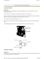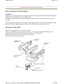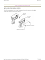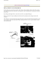
1
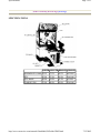
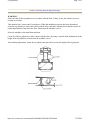
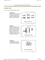
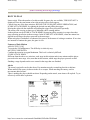
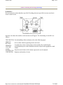
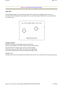
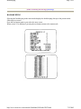
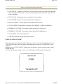
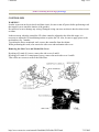
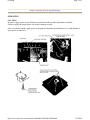
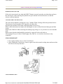
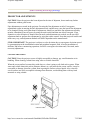
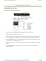
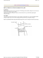
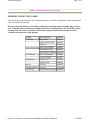
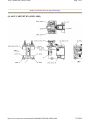
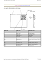
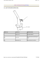
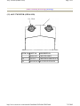
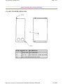
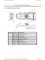
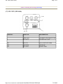
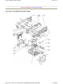
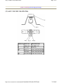
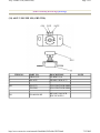
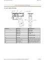
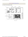
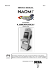
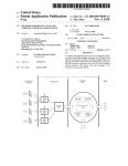
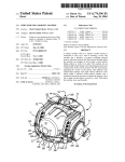
Gunblade NY Service Manual
Page 1 of 2
GUNBLADE DELUXE TABLE OF CONTENTS
INTRODUCTION OF THE OWNER'S
MANUAL
GENERAL PRECAUTIONS
INSTALLATION LOCATION PRECAUTIONS
SAFETY AND REGULATORY
INFORMATION
GAME REGISTRATION (not included)
SPECIFICATIONS
INSTALLATION ITEMS
ASSEMBLING THE MACHINE
LEG ADJUSTERS
ASSEMBLY CHECKS
OPERATION
HOW TO PLAY
EXPLANATION OF TEST AND DATA
DISPLAYS
SWITCH UNIT
TEST MODE
MEMORY TEST
INPUT TEST
OUTPUT TEST
SOUND TEST
CRT TEST
GAME ASSIGNMENTS
COIN ASSIGNMENT
COIN CREDITS
MANUAL SETTINGS
AIM SET
BOOKEEPING
BACK UP DATA CLEAR
SERVICE INFORMATION
CONTROLLER
VR ADJUSTMENT
TRIGGER SWITCH
MICRO SWITCH
MOTOR BRUSH
GREASING
COIN SELECTOR
http://www.sauservice.com/manuals/Gunblade%20Folder/GB00.html
1
2
3
3
4
5
6
7
13
14
17
18
19
20
21
22
23
24
25
26
27
28
29
30
32
33
34
35
36
37
38
39
40
41
7/12/2005
Gunblade NY Service Manual
PROJECTOR CARE AND
ADJUSTMENT
STATIC CONVERGENCE
ADJUSTMENT
FLUORESCENT LAMP
PERIODIC INSPECTION
TROUBLESHOOTING
GAME BOARD
GAME BOARD SERVICE RECORD (not
included)
DESIGN RELATED PARTS
PARTS IDENTIFICATION
PARTS REPLACEMENT RECORD (not
included)
MANUAL COMMENTS
WIRING DIAGRAM
http://www.sauservice.com/manuals/Gunblade%20Folder/GB00.html
Page 2 of 2
42
43
45
46
47
49
51
52
53
85
86
87
7/12/2005
Introduction of the Owners Manual
Page 1 of 1
[Table of Contents] [Next Page]
INTRODUCTION OF THE OWNERS MANUAL
SEGA ENTERPRISES, LTD., has for more than 30 years been supplying various innovative and
popular amusement products to the world market. This Owners Manual is intended to provide detailed
descriptions together with all the necessary installation, game settings and parts ordering information
related to GUN BLADE NY, a new SEGA product.
This manual is intended for those who have knowledge of electricity and technical expertise, especially
in ICs, CRTs, microprocessors, and circuit boards. Read this manual carefully to acquire sufficient
knowledge before working on the machine. Should there be a malfunction, non-technical personnel
should under no circumstances touch the interior system. Should the need arise, contact our main office
or the closest branch office listed below.
SEGA ENTERPRISES, INC. (USA)
Customer Service
45133 Industrial Drive
Fremont, CA 94538
Phone 415-802-1750
Fax 415-802-1754
7:30 am - 4:00 pm, Pacific Standard Time
Monday thru Friday
http://www.sauservice.com/manuals/Gunblade%20Folder/GB01.html
7/12/2005
General Precautions
Page 1 of 2
[Table of Contents] [Previous Page] [Next Page]
General Precautions
Follow Instructions: All operating and use instructions should be followed.
Attachments: Do not use attachments not recommended by the product manufacturer as they may
cause hazards.
Accessories: Do not place this product on an unstable cart, stand, tripod, bracket, or table. The
product may fall, causing serious injury to a child or adult, and serious damage to the product. Use only
with a cart, stand, tripod, bracket, or table recommended by the manufacturer, or sold with the product.
Any mounting of the product should follow the manufacturer's instructions, and should use only
mounting accessories recommended by the manufacturer.
Moving the Product: This product should be moved with care. Quick stops, excessive force, and
uneven surfaces may cause the product to overturn.
Ventilation: Slots and openings in the cabinet are provided for ventilation, to ensure reliable
operation of the product and to protect it from overheating; these openings must not be blocked or
covered. The openings should never be blocked by placing the product in a built-in installation such as a
bookcase or rack unless proper ventilation is provided or the manufacturer's instructions have been
adhered to.
Power Sources: This product should be operated only from the type of power source indicated on
the marking label. If you are not sure of the type of power supply to your location, consult your local
power company. For products intended to operate from battery power or other sources, refer to the
operating instructions.
Grounding or Polarization: This product is equipped with a three-wire grounding-type plug, a
plug having a third (grounding) pin. This plug will only fit into a grounding-type power outlet. This is a
safety feature. If you are unable to insert the plug into the outlet, contact your electrician to replace your
obsolete outlet. Do not defeat the safety purpose of the grounding-type plug.
Power Cord Protection: Power-supply cords should be routed so that they are not likely to be
walked on or pinched by items placed upon or against them, paying particular attention to cords at plugs,
convenience receptacles, and the point where they exit from the product.
Overloading: Do not overload wall outlets, extension cords, or integral convenience receptacles
as this can result in a risk of fire or electric shock.
Object and Liquid Entry: Never push objects of any kind into this product through openings as
they may touch dangerous voltage points or short-out parts that could result in a fire or electric shock.
Never spill liquid of any kind on the product.
Servicing: Do not attempt to service this product yourself as opening or removing covers may
expose you to dangerous voltage or other hazards. Refer all servicing to qualified service personnel.
Damage Requiring Service: Unplug this product from the wall outlet and refer servicing to
http://www.sauservice.com/manuals/Gunblade%20Folder/GB02.html
7/12/2005
General Precautions
Page 2 of 2
qualified service personnel under the following conditions:
a) If the power cord or plug is damaged;
b) If liquid has been spilled, or objects have fallen into the product;
c) If the product has been exposed to rain or water;
d) If the product does not operate normally when following the operating instructions.
Adjust only those controls that are explained in the operating instructions. An improper
adjustment of other controls may result in damage and will often require extensive work by
a qualified technician to restore the product to its normal operation;
e) If the product has been dropped or damaged in any way;
f) When the product exhibits a distinct change in performance; this indicates a need for
service.
Replacement Parts: When replacement parts are required, be sure the service technician has used
replacements parts specified by the manufacturer or that have the same characteristics as the original
part. Unauthorized substitutions may result in fire, electric shock, or other hazards.
http://www.sauservice.com/manuals/Gunblade%20Folder/GB02.html
7/12/2005
General Precautions (cont.)
Page 1 of 1
[Table of Contents] [Previous Page] [Next Page]
Safety Check: Upon completion of any service or repairs to this product, ask the service
technician to perform safety checks to determine that the product is in proper operating condition.
Heat: The product should be situated away from heat sources such as radiators, heat registers,
stoves, or other products (including amplifiers) that produce heat.
Cleaning: When cleaning the monitor glass, use water or glass cleaner and a soft cloth. Do not
apply chemicals such as benzene, thinner, etc.
Location: This an indoor game machine, DO NOT install it outside. To ensure proper usage,
avoid installing indoors in the places mentioned below:
z
z
z
z
z
z
z
z
z
Places subject to rain/water leakage, or condensation due to humidity;
In close proximity to a potential wet area;
Locations receiving direct sunlight;
Places close to heating units or hot air;
In the vicinity of highly inflammable/volatile chemicals or hazardous matter;
On sloped surfaces;
In the vicinity of emergency response facilities such as fire exits and fire extinguishers;
Places subject to any type of violent impact;
Dusty places.
INSTALLATION PRECAUTIONS
z
z
z
z
Verify the amperage of the branch circuit outlet before plugging in the power plug. Do not
overload the circuit.
Avoid using an extension cord. If one is required, use an extension cord of type SJT, 16/3 AWG
rated min. 120 VAC, 7A.
Moving this unit requires a minimum clearance (of doors, etc.) of 32" (W) by 77" (H).
For the operation of this machine, secure a minimum area of 32" (W) by 42"(D).
REGULATORY APPROVALS
This game has been tested and found to comply with the Federal Communications Commission
Rules.
This device complies with Part 15 of the FCC Rules. Operation is subject to the following two
conditions: (1) This device may not cause harmful interference, and (2) this device must accept any
interference received, including interference that may cause undesired operation.
This game has been tested and listed by Underwriters Laboratories, Inc., to ANSI/UL22.
http://www.sauservice.com/manuals/Gunblade%20Folder/GB03.html
7/12/2005
Specifications
Page 1 of 1
[Table of Contents] [Previous Page] [Next Page]
SPECIFICATIONS
WIDTH LENGTH HEIGHT WEIGHT
ASSEMBLED GAME 48 IN
73 IN
89 IN
662 LBS
PTV
PTV BASE
CABINET DX
45 IN
48 IN
33 IN
27 IN
24 IN
48 IN
82 IN
11 IN
50 IN
http://www.sauservice.com/manuals/Gunblade%20Folder/GB05.html
298 LBS
45 LBS
320 LBS
7/12/2005
Installation Items
Page 1 of 1
[Table of Contents] [Previous Page] [Next Page]
INSTALLATION ITEMS
The following items are supplied with the machine. Be sure that these items remain with the game if it is
transported or sold.
1 Service Manual, Gun Blade NY
1 Tamperproof wrench, M4
1 Tamperproof wrench, MS
1 Remote Controller, Mitsubishi Projection TV
http://www.sauservice.com/manuals/Gunblade%20Folder/GB06.html
7/12/2005
Assembly and Precautions
Page 1 of 1
[Table of Contents] [Previous Page] [Next Page]
ASSEMBLY AND PRECAUTIONS
z
z
z
Perform the assembly work by following the procedure stated herein. Failing to comply with the
instructions can cause an injury or electrical shock.
Assembly should be performed as per the instructions in this manual. This is a complex machine
and erroneous assembly can cause electrical shock or damage to the machine resulting in
undesired operation.
When assembling the machine, be sure that more than one person is available to perform the
work. Depending on the assembly work, there are some cases in which performing the work alone
can cause personal injury or damage the game.
When carrying out the assembly work, follow the procedure in the following sequence:
1 Assembling the PTV
2 Assembling the cabinet
3 Securing in place (leg adjusters)
4 Power supply
5 Assembly check
ASSEMBLING THE PTV
The PTV unit for this game is shipped assembled. However, refer to these directions if you should need
to disassemble the PTV unit for maintenance.
WARNING!
When performing work on the PTV unit, be sure that two or more persons are available to do the work.
When mounting the PTV on the PTV base, be sure that the work is performed by 4 or more persons.
Executing the work by less than 4 persons can cause severe injury.
CAUTION!
To perform the work safely, be sure to prepare a step or ladder which is secure and stable. Using an
unstable step can cause both personal injury and damage to the product.
http://www.sauservice.com/manuals/Gunblade%20Folder/GB07.html
7/12/2005
Leg Adjusters
Page 1 of 1
[Table of Contents] [Previous Page] [Next Page]
WARNING!
Make sure that all the leg adjusters are in contact with the floor. If they are not, the cabinet can move,
causing an accident.
This machine has 8 casters and 6 leg adjusters. When the installation position has been determined,
cause the leg adjusters to come into contact with the floor, and make adjustments so that the casters are
raised approximately 5mm from the floor. Ensure that the machine is level.
Move the machine to the installation position.
Cause all of the leg adjusters to make contact with the floor. By using a wrench, make adjustments in the
height of the leg adjusters to ensure that the machine is level.
After making adjustments, fasten the leg adjuster nut upwards to secure the height of the leg adjuster.
http://www.sauservice.com/manuals/Gunblade%20Folder/GB13.html
7/12/2005
Assembly Checks
Page 1 of 1
[Table of Contents] [Previous Page] [Next Page]
Assembly Checks
In the test mode, perform the following tests:
http://www.sauservice.com/manuals/Gunblade%20Folder/GB14.html
7/12/2005
Operation
Page 1 of 1
[Table of Contents] [Previous Page] [Next Page]
OPERATION
To ensure safe operation of the product, be sure to comply with all the following
precautions.
WARNING!
Be sure that all the leg adjusters are in contact with the floor surface. If they are not, the cabinet can
move and cause an accident.
Do not put any heavy items on the product. Placing heavy items on the product can cause a accident. Do
not climb on the game. Climbing on the game can cause accidents as well as damage to the controller
and other parts. To inspect the upper portion of the game, use a sturdy step or ladder.
CAUTION!
To avoid electric shock, check to see if door and cover parts are damaged or omitted.
To avoid accidents, be sure to provide a sufficient space for operation by considering the most crowded
situations. Insufficient space for operation can cause customers to come in contact with the moving parts
of the game and hit each other, resulting in injury.
To avoid injury and trouble, be sure to pay careful attention to the behavior of players and
visitors.
WARNING!
To avoid electric shock and short circuit, do not allow customers to put hands and fingers or extraneous
matter into openings of product or small openings in and around the doors.
To avoid falls or injuries, prevent customers from leaning on or climbing on the game.
To avoid electric shock, do not allow the customers to unplug the power plug without good reason.
To avoid injury resulting from falling objects or electric shock due to spilled liquids, do not allow
customers to place heavy items or drinks on the machine.
CAUTION!
Immediately stop such violent acts as hitting and kicking the product. Such acts can cause damage to
parts or breakage, resulting in injury from falling fragments.
http://www.sauservice.com/manuals/Gunblade%20Folder/GB17.html
7/12/2005
How to Play
Page 1 of 1
[Table of Contents] [Previous Page] [Next Page]
HOW TO PLAY
Insert coin(s). When the number of credits needed for game play are available, "PRESS START" is
displayed. Press the start button to have the mission select screen appear.
Choose from one of the three missions, REGAIN THE UN HQ, BIG APPLE LIBERATION, and
SCORE ATTACK REMIX, by sighting the desired one and pulling the trigger.
Moving the sight with the controller and pulling the trigger fires projectiles repeatedly.
The enemy who is trying to shoot you is indicated with a warning marker.
In the missions except SCORE ATTACK REMIX, destroying all the enemies in a stage clears that
stage, allowing procession to the next stage. In the SCORE ATTACK REMIX, when one minute has
elapsed in each stage, the player proceeds to the next stage.
When each player's endurance is exhausted, the game is in the status of waiting to continue. If no coins
are inserted to continue the game, the game is over.
Features of Each Mission
REGAIN THE UN HQ
To regain the UN headquarters. The difficulty is relatively easy.
BIG APPLE LIBERATION
Confront the terrorists to regain Manhattan. This level is relatively difficult.
SCORE ATTACK REMIX
Different from the above two missions, each stage in this mission ends in one minute and the player
proceeds to the next stage. Also, note that in this mission, which stage the player proceeds to after
finishing a stage depends on the score earned in the stage that was finished.
Advice
The enemy's projectile can be shot down. Pay attention not only to attacking but also to defense.
When attacked, the enemy is thrown in the air or escapes. When attacking the enemy, read its
movements ahead of time.
There is nothing the player should not shoot. Depending on the attack, some items will explode. Try to
effectively utilize these explosions.
http://www.sauservice.com/manuals/Gunblade%20Folder/GB18.html
7/12/2005
Explanation of Test and Data Display
Page 1 of 2
[Table of Contents] [Previous Page] [Next Page]
EXPLANATION OF TEST AND DATA DISPLAY
By operating the switch unit, periodically perform the tests and data check. When installing the machine
initially, or collecting cash, or when the machine does not function properly, perform checks in
accordance with this section.
The following test modes should be utilized as applicable.
Items
Installation of Machine
Memory
Monthly Servicing
Control System
Monitor
Description
When the machine is installed,
perform the following:
1. Check to see that each setting
is per standard setting made at the
time of shipment.
2. In the INPUT test mode, check
each SW and VR.
3. In the OUTPUT test mode,
check each of the lamps, motors,
etc.
4. In the MEMORY test mode,
check the IC's on the PC board.
Choose MEMORY test in the
MENU mode to allow the
memory test to be performed. In
this test, PROGRAM RAMs,
ROMs and IC s on the PC board
are checked.
Monthly perform the following:
1. MEMORY test.
2. Ascertain each setting.
3. In the INPUT test mode, test
the CONTROL device.
4. In the OUTPUT test mode,
check each of the lamps.
In the INPUT test mode, check
each SW and VR.
Adjust or replace each SW or
VR.
If the problem can not be solved
yet, check the CONTROL's
moves.
In the MONITOR
ADJUSTMENT mode, check to
http://www.sauservice.com/manuals/Gunblade%20Folder/GB19.html
7/12/2005
Explanation of Test and Data Display
Page 2 of 2
see if the MONITOR adjustment
is correct.
IC Board
Data Check
1. MEMORY TEST
2. In the SOUND test mode,
check the sound related ROMs.
Check such data as game play
time and histogram to adjust the
difficulty level, etc.
http://www.sauservice.com/manuals/Gunblade%20Folder/GB19.html
7/12/2005
Switch Unit
Page 1 of 1
[Table of Contents] [Previous Page] [Next Page]
WARNING!
Do not touch places other than those specified. Touching places not specified can cause an electric
shock or short circuit.
Open the coin chute door and the switch unit shown will appear. The functioning of each SW is as
follows:
TEST BUTTON For the handling of the test button, refer to the following pages.
SERVICE
Gives credits without registering on the coin meter.
BUTTON
Can adjust the volume of all speakers of the machine. By considering the
SPEAKER
environmental aspects of the installation location, adjust to the appropriate sound
VOLUME
volume.
SUPER
Only the sound volume of the cabinet superwoofer can be adjusted.
WOOFER VOL
COIN METER Registers total number of coins.
http://www.sauservice.com/manuals/Gunblade%20Folder/GB20.html
7/12/2005
Test Mode
Page 1 of 1
[Table of Contents] [Previous Page] [Next Page]
Test Mode
The Test Menu allows the functioning of each part of the Cabinet to be checked, the monitor to be
adjusted, and the coins and game related various settings to be performed.
z
Press the Test Button to cause the following Test Menu to be displayed on the monitor.
z
Press the Service Button until the arrow ---> is moved to the desired item to make a selection.
z
Bring the arrow ---> to the desired item and press the Test Button to enter the selected item's test.
z
Choosing EXIT and pressing the Test Button will finish the test mode, and the game mode returns
on the screen after network checking.
http://www.sauservice.com/manuals/Gunblade%20Folder/GB21.html
7/12/2005
Memory Test
Page 1 of 1
[Table of Contents] [Previous Page] [Next Page]
Memory Test
The Memory Test mode is for checking the on-board memory IC functioning. GOOD is displayed for
normal ICs and BAD is displayed for abnormal ICs.
z
When the test is completed, if the results are shown as below, it is satisfactory.
z
When the test is not finished, IC Board malfunctioning may be the cause.
z
After finishing the test, press the Test button to return to the Menu mode.
http://www.sauservice.com/manuals/Gunblade%20Folder/GB22.html
7/12/2005
Page 1 of 1
[Table of Contents] [Previous Page] [Next Page]
Input Test
When Input Test is selected, the monitor will show the following, allowing you to watch the status of
each switch. On this screen, periodically check the status of each switch.
z
By pressing each switch, if the display on the right-hand side of the name of each switch changes
to ON from OFF, the switch and the wiring connections are satisfactory. When the Controller
(Lever) is operated in the direction of the arrow, the right-hand side indication of the Switch name
becomes ON.
z
To check Coin Chute #1 and Coin Chute #2 Coin Switches, open the Coin Chute Door and insert
coin(s) into the slot.
z
To return to the Menu mode, press the Test button.
http://www.sauservice.com/manuals/Gunblade%20Folder/GB23.html
7/12/2005
Output Test
Page 1 of 1
[Table of Contents] [Previous Page] [Next Page]
Output Test
Selecting Output Test allows the status of each lamp to be viewed. Periodically check the status of each
lamp on this screen.
<--- Repeatedly displays sequentially in order of Winner Lamp, 7-SEG. At this time lamp and 7-SEG LED tests are performed in the manner corresponding to the item displayed.
This game does not have 7-SEG LED. During the display of 7-SEG, only the Start button flashes.
z
z
While this screen is displayed, the Start button continues to flash.
Press the Test button to return to the menu mode.
http://www.sauservice.com/manuals/Gunblade%20Folder/GB24.html
7/12/2005
Sound Test
Page 1 of 1
[Table of Contents] [Previous Page] [Next Page]
Sound Test
Selecting Sound Test allows sounds (sound effects, announcement, background music, etc.) to be chosen
and heard. In this mode, check the sound-related IC Board and each speaker. Press the Service button to
bring the arrow ---> to the desired sound item. Press the Test button to have the selected sound played.
Each time the Test button is pressed, the next sound is played.
http://www.sauservice.com/manuals/Gunblade%20Folder/GB25.html
7/12/2005
CRT Test
Page 1 of 1
[Table of Contents] [Previous Page] [Next Page]
CRT Test
Choose CRT Test to display the screen on which the Monitor adjustment is checked. By watching the
screen, periodically check if adjustments are needed or not. For adjustment, refer to the Section of
Monitor Adjustment stated herein.
In figure below, check the Monitor's color adjustment. Perform color adjustment by watching this
screen.
The color bar of 4 colors i.e. red, green blue and white is darkest at the left end and becomes brighter
towards the right end.
Pressing the Test button will have the following crosshatch screen appear.
In this figure, check the Monitor size and position adjustment by watching the screen.
Adjust the Monitor in the manner so that the crosshatch lines to not go beyond the screen. Adjust the
Monitor to ensure that crosshatch lines do not have distortions.
Press the Test button to return to the menu mode.
http://www.sauservice.com/manuals/Gunblade%20Folder/GB26.html
7/12/2005
Game Assignments
Page 1 of 1
[Table of Contents] [Previous Page] [Next Page]
Game Assignments
Selecting Game Assignments will have the following screen appear, allowing play time, game
difficulty, etc. to be set. Refer to the following for the contents of each item.
Before exiting the setting will not be changed. Be sure to press test to Exit after changing the
setting. This will store your settings.
Game
Difficulty
Advertise
Sound
Country
Cabinet
Type
Game difficulty can be varied by changing the enemy missile speed or the ratio of
damage the player suffers when attacked, etc. Choose from among 4 levels, Easy,
Normal, Hard, Hardest.
Set this to ON to have sound produced during Demo mode, and OFF for no sound.
Message language. Select USA for USA and Export for other countries.
Set to Deluxe or Standard, depending on which type is applicable.
http://www.sauservice.com/manuals/Gunblade%20Folder/GB27.html
7/12/2005
Coin Assignment
Page 1 of 1
[Table of Contents] [Previous Page] [Next Page]
Coin Assignments
This mode permits you to set the start number of credits, as well as the basic numbers of coins and
credits. This mode expresses "how many coins correspond to how many credits".
Setting change is not effective until Exiting. Be sure to Press test to Exit after setting change.
Credit to Start
Credit to
Continue
Coin/Credit
Setting
Manual Setting
Sets the number of credits required when starting the game.
This sets the number of credits required to continue game.
How many coins correspond to how many credits. In this machine, selection as per
the adjacent chart is possible.
Allows for finer settings. See chart.
1. Press the Service button or Shift button to bring the arrow to the desired change item.
2. Press the Test button or the Start button to select the setting change item.
3. Move the arrow to Exit and press the Test button or the Start button to return the menu mode to
the screen.
http://www.sauservice.com/manuals/Gunblade%20Folder/GB28.html
7/12/2005
Coin Credits
Page 1 of 2
[Table of Contents] [Previous Page] [Next Page]
COIN/CREDIT SETTING (COIN CHUTE COMMON TYPE)
NAME OF
SETTING
SETTING #1
SETTING #2
SETTING #3
SETTING #4
SETTING #5
SETTING #6
SETTING #7
SETTING #8
SETTING #9
SETTING #10
SETTING #11
SETTING #12
SETTING #13
SETTING #14
SETTING #15
FUNCTIONING OF COIN
CHUTE #1
1 COIN, 1 CREDIT
1 COIN, 2 CREDITS
1 COIN, 3 CREDITS
1 COIN , 4 CREDITS
1 COIN, 5 CREDITS
1 COIN, 2 CREDITS
1 COIN, 5 CREDITS
1 COIN, 3 CREDITS
1 COIN, 4 CREDITS
1 COIN, 5 CREDITS
1 COIN, 6 CREDITS
2 COINS, 1 CREDIT
1 COIN, 1 CREDIT
1 COIN, 2 CREDITS
1 COIN, 1 CREDIT
2 COINS, 3 CREDITS
SETTING #16
1 COIN, 3 CREDITS
SETTING #17
SETTING #18
3 COINS, 1 CREDIT
4 COINS, 1 CREDIT
1 COIN, 1 CREDIT
2 COINS, 2 CREDITS
3 COINS, 3 CREDITS
4 COINS, 5 CREDITS
SETTING #19
SETTING #20
1 COIN, 5 CREDITS
SETTING #21
5 COINS, 1 CREDIT
SETTING #22
1 COIN, 2 CREDITS
SETTING #23
2 COIN, 1 CREDIT
4 COIN, 2 CREDITS
5 COIN, 3 CREDITS
SETTING #24
1 COIN, 3 CREDITS
SETTING #25
1 COIN, 1 CREDIT
2 COINS, 2 CREDITS
3 COINS, 3 CREDITS
4 COINS, 4 CREDITS
5 COINS, 6 CREDITS
FUNCTIONING OF COIN
CHUTE #2
1 COIN, 1 CREDIT
1 COIN, 1 CREDIT
1 COIN, 1 CREDIT
1 COIN, 1 CREDIT
1 COIN, 1 CREDIT
1 COIN, 2 CREDITS
1 COIN, 2 CREDITS
1 COIN, 3 CREDITS
1 COIN, 4 CREDITS
1 COIN, 5 CREDITS
1 COIN, 6 CREDITS
2 COINS, 1 CREDIT
2 COIN, 1 CREDIT
2 COIN, 1 CREDIT
1 COIN, 1 CREDIT
2 COINS, 3 CREDITS
1 COIN, 1 CREDIT
2 COINS, 3 CREDITS
3 COINS, 1 CREDIT
4 COINS, 1 CREDIT
1 COIN, 1 CREDIT
2 COINS, 2 CREDITS
3 COINS, 3 CREDITS
4 COINS, 5 CREDITS
1 COIN, 1 CREDIT
2 COINS, 2 CREDITS
3 COINS, 3 CREDITS
4 COINS, 5 CREDITS
5 COINS, 1 CREDIT
1 COIN, 1 CREDIT
5 COINS, 2 CREDITS
2 COIN, 1 CREDIT
4 COIN, 2 CREDITS
5 COIN, 3 CREDITS
1 COIN, 1 CREDIT
4 COIN, 2 CREDITS
5 COIN, 3 CREDITS
1 COIN, 1 CREDIT
2 COINS, 2 CREDITS
3 COINS, 3 CREDITS
4 COINS, 4 CREDITS
5 COINS, 6 CREDITS
1 COIN, 1 CREDIT
2 COINS, 2 CREDITS
http://www.sauservice.com/manuals/Gunblade%20Folder/GB29.html
7/12/2005
Coin Credits
Page 2 of 2
SETTING #26
1 COIN, 6 CREDITS
SETTING #27
FREE PLAY
3 COINS, 3 CREDITS
4 COINS, 4 CREDITS
5 COINS, 6 CREDITS
FREE PLAY
http://www.sauservice.com/manuals/Gunblade%20Folder/GB29.html
7/12/2005
Manual Settings
Page 1 of 1
[Table of Contents] [Previous Page] [Next Page]
MANUAL SETTINGS
8 - Determines conversion of coin/credit.
9 - This sets how many conversion coins should be inserted to obtain one service coin.
10 - This sets how many conversion coins are represented by a coin inserted in coin chute one.
11 - This sets how many conversion coins are represented by a coin inserted in coin chute two.
http://www.sauservice.com/manuals/Gunblade%20Folder/GB30.html
7/12/2005
Aim Set
Page 1 of 1
[Table of Contents] [Previous Page] [Next Page]
AIM SET
By adjusting the guns' VR value from the aspect of the software, the sighting position can be set
correctly. After VR adjustment and replacement, or game board replacement, but sure to perform Aim
Set on this screen.
Setting Procedure
Pull the 1P (left player) gun trigger one time and release.
Move the 1P gun fully to all of its mechanical stops (all directions).
Pull and release the 1P gun trigger again to store the settings.
Perform the same procedure (steps 1-3) on 2P gun (right player).
Press the test button to have the menu mode return to the screen.
IMPORTANT!
The above procedure must be performed each time the aim set test is entered to assure proper game play.
http://www.sauservice.com/manuals/Gunblade%20Folder/GB32.html
7/12/2005
Bookkeeping
Page 1 of 1
[Table of Contents] [Previous Page] [Next Page]
BOOKKEEPING
Selecting the bookkeeping in the menu mode displays the bookkeeping data up to the present on the
following two screens.
Press the test button again to proceed to the next screen.
When screen 2/2 is displayed, pressing the test button returns to the menu mode.
http://www.sauservice.com/manuals/Gunblade%20Folder/GB33.html
7/12/2005
Backup Data Clear
Page 1 of 1
[Table of Contents] [Previous Page] [Next Page]
z
COIN CHUTE~ : Number of coins put in. As seen from the front of the cabinet, the right-hand
side is #1 and the left-hand side is #2. Note that depending on the destinations, only one Coin
Chute is available.
z
TOTAL COIN : Total number of coins inserted in each coin chute.
z
COIN CREDIT : Number of credits registered by inserting coins.
z
SERVICE CREDIT : Credits registered by the SERVICE BUTTON.
z
TOTAL CREDIT : Total number of credits (COIN CREDITS + SERVICE CREDITS).
z
NUMBER OF 1P GAME : The number of game played by 1P (Left Player).
z
NUMBER OF 2P GAME : The number of game played by 2P (Right Player).
z
TOTAL TIME : The total energized time.
z
TIME HISTOGRAM : By-playtime play frequency.
BACK UP DATA CLEAR
Clears the contents of bookkeeping. When clearing, use the service button to bring the arrow (>) to
"YES (CLEAR)" and press the test button. When data has been cleared, "COMPLETED" will be
displayed.
Bring the arrow to "NO (CANCEL)" and press the test button to return to the menu mode without
clearing the data.
Also, note that the game setting contents are not affected by the backup data clear operation.
http://www.sauservice.com/manuals/Gunblade%20Folder/GB34.html
7/12/2005
Controller
Page 1 of 1
[Table of Contents] [Previous Page] [Next Page]
CONTROLLER
WARNING!
In order to prevent an electric shock and short circuit, be sure to turn off power before performing work
that requires you to touch the interior of the product.
Be careful so as not to damage any wiring. Damaged wiring can cause an electric shock or short circuit
accident.
In the test menu, when the controllers VR values cannot be adjusted to the allowable range, it is
necessary to adjust the VR installation position or replace the VR. Also, be sure to apply grease to the
mechanism every 3 months.
To perform the above-mentioned work, remove the controller from the cabinet.
When performing this work, also remove the side cover and mechanism side cover.
Removing the Side Cover and Mecha Side Cover
By taking off a total of 8 screws, remove the side covers L and R.
By taking off a total of 11 tamperproof screws, remove the mech side cover L and R.
Take off the two screws to remove the Hide Plate.
http://www.sauservice.com/manuals/Gunblade%20Folder/GB35.html
7/12/2005
VR Adjustment
Page 1 of 2
[Table of Contents] [Previous Page] [Next Page]
VR ADJUSTMENT
WARNING!
Do not touch places other than those specified. Touching places not specified can cause an electric
shock or short circuit.
Loosen the 2 screws which secure the VR bracket in order to move the bracket.
Move the VR bracket to disengage the adjust gear mesh and move the VR shaft in a manner so that the
VR shaft cut portion faces the opposite side of the adjust gear as shown.
Have the gears meshed and tighten the two screws.
Slowly swing the controller up and down, left and right to check if the value exceeded the VR mobile
range.
After finishing adjustments, be sure to set sights on the aim set screen in the test mode.
VR REPLACEMENT
WARNING!
In order to prevent an electric shock and short circuit, be sure to turn off power before performing work
by touching the interior parts of the product.
http://www.sauservice.com/manuals/Gunblade%20Folder/GB36.html
7/12/2005
VR Adjustment
Page 2 of 2
By removing the cord clamp, first remove the VR blue 3P for up/down and VR red 3P for left/right.
Take off the two screws which secure the VR bracket to remove the bracket.
Remove volume gear from the VR to replace the VR.
After replacing the VR, perform work by following the procedure as per VR adjustment.
http://www.sauservice.com/manuals/Gunblade%20Folder/GB36.html
7/12/2005
Trigger Switch
Page 1 of 1
[Table of Contents] [Previous Page] [Next Page]
REPLACEMENT OF TRIGGER SW
WARNING!
In order to prevent an electric shock and short circuit be sure to turn off power before performing work
which involves touching the interior of the product.
Be careful so as not to damage wiring. Damaged wiring can cause an electric shock or short circuit
accident.
When the trigger is pulled, if ON is not shown in the trigger display in then test menu input test screen,
the micro sw may be malfunctioning. In that case it is necessary to replace the micro sw.
REMOVING THE GRIP
Take off 7 tamperproof screws A and cover right.
Take off 5 tamperproof screws A and remove the cover left with cover bracket attached to it. Pay
attention to the wires attached to the bracket so that they are not damaged.
Disconnect the connector which is connected to the grip.
Remove 6 U nuts to remove the grip.
http://www.sauservice.com/manuals/Gunblade%20Folder/GB37.html
7/12/2005
Micro Switch
Page 1 of 1
[Table of Contents] [Previous Page] [Next Page]
REPLACING THE MICRO SWITCH
Take off two tamperproof screws A and 3 tamperproof screws B to remove the Grip Right.
In this status, the micro switch can be replaced.
http://www.sauservice.com/manuals/Gunblade%20Folder/GB38.html
7/12/2005
Motor Brush
Page 1 of 1
[Table of Contents] [Previous Page] [Next Page]
REPLACEMENT OF MOTOR BRUSH
On the output test screen in the test mode, when 1P gun or 2P gun display indicates ON, if the gun does
not vibrate, first check the switch unit's circuit protector. If the circuit protector is satisfactory, check the
motor brush.
By referring to the figures below, remove the cover left, cover right and the grip.
Remove a total of 6 U nuts to withdraw the slide mecha. Pay attention to the wirings to remove the
connector.
Take off the two screws from the lower part of the motor to remove the brush. If the motor brush is worn
away as shown, replace the motor brush. When replacing the brush, be sure to replace brushes for both
sides simultaneously.
http://www.sauservice.com/manuals/Gunblade%20Folder/GB39.html
7/12/2005
Greasing
Page 1 of 1
[Table of Contents] [Previous Page] [Next Page]
GREASING
CAUTION!
Be sure to apply grease to specified parts as indicated in the periodic maintenance schedule.
Failure to apply the proper grease can result in damage to parts.
Once every three months, apply grease to the game mechanisms specified below. Use white lithium or
spray grease as indicated.
http://www.sauservice.com/manuals/Gunblade%20Folder/GB40.html
7/12/2005
Coin Selector
Page 1 of 2
[Table of Contents] [Previous Page] [Next Page]
HANDLING THE COIN JAM
If the coin is not rejected even when the REJECT button is pressed, open the coin chute door and open
the selector gate. After removing the jammed coin, put a normal coin in and check to see that the
selector correctly functions.
CLEANING THE COIN SELECTOR
The coin selector should be cleaned once every 3 months. When cleaning, follow the procedure below:
Turn the power for the machine OFF. Open the coin chute door.
Open the gate and dust off by using a soft brush (made of wool, etc.).
Remove and clean smears by using a soft cloth dipped in water or diluted chemical detergent and then
wrung.
Remove the CRADLE. When removing the retaining ring (E ring). be very careful so as not to bend the
shaft.
Remove stain from the shaft and pillow portions by wiping off with a soft cloth, etc.
After wiping off as per (5) above, further apply a dry cloth, etc. to cause the coin selector to dry
completely.
STOP: IMPORTANT!
z
z
Never apply machine oil, etc. to the Coin Selector.
After cleaning the Coin Selector, insert a regular coin in the normal working status and ensure that
the Selector correctly functions.
COIN INSERTION TEST
http://www.sauservice.com/manuals/Gunblade%20Folder/GB41.html
7/12/2005
Coin Selector
Page 2 of 2
Once every month when performing the Coin SW Test, simultaneously check the following:
z
z
z
Does the Coin Meter count satisfactorily?
Does the coin drop into the Cash box correctly?
Is the coin rejected when inserted while keeping the Reject Button pressed down?
http://www.sauservice.com/manuals/Gunblade%20Folder/GB41.html
7/12/2005
Projector Adjustment
Page 1 of 1
[Table of Contents] [Previous Page] [Next Page]
PROJECTOR ADJUSTMENTS
CAUTION! Since the projector has been adjusted at the time of shipment, do not make any further
adjustments without good reason.
Fine adjustments are stored in the projector. Pressing the fine adjustment switch (Convergence
adjustment) results in entering the fine adjustments mode, and this may cause the stored fine adjustment
to be changed. During work other than for adjustment, should you touch the fine adjustment switch by
mistake, immediately turn off power by using the main switch and then turn it back on again. If any
distortion or color deviation is found in the test mode, and adjustments are needed, use the specified
adjustment knob or perform the adjustments by using the remote control. Note that projector models and
makes may vary, and adjustment methods will differ dependent on the manufacturer.
STOP: IMPORTANT! The projector is subject to color deviation due to convergence deviation caused
by geomagnetism at the installation location and peripheral magnetic field. After the installation of
machine, and before commencing operation, check for convergence deviation and, if deviated, make
necessary adjustments.
CLEANING THE SCREEN
CAUTION! Since the projector screen is highly susceptible to damage, pay careful attention to its
handling. When cleaning, refrain from using water or volatile chemicals.
When the screen surface becomes dirty with dust, etc, clean it using a soft cloth such as gauze. When
water and volatile chemicals such as benzene, thinner, etc, spill onto the the screen surface, it may be
susceptible to damage, therefore, refrain from exposing the surface to these liquids. Also, since the
screen surfaces are easily susceptible to damage from abrasion, avoid rubbing them with any hard
materials or using a duster.
http://www.sauservice.com/manuals/Gunblade%20Folder/GB42.html
7/12/2005
Static Convergence Adjustment
Page 1 of 1
[Table of Contents] [Previous Page] [Next Page]
MITSUBISHI PROJECTOR
MITSUBISHI PROJECTOR CONTROL PANEL
z
For the Convergence adjustment mode, press the test mode on/off key (12).
z
Ensure that "R" is displayed on the screen.
z
Make adjustment so as to cause the red cross pattern to match with the green cross pattern by
using Left shift key (14), Right shift key (15), Lower shift key (16), and Upper shift key (17).
z
By using R/B shift key (13), cause the red adjustment "R" to shift to blue adjustment "B" and
make sure that "B" is displayed on the screen.
z
In the same manner as in (3) above, cause the blue cross pattern to match with the green cross
pattern.
z
After making adjustment, press the test mode on/off key (12) to cancel the Convergence
adjustment mode.
http://www.sauservice.com/manuals/Gunblade%20Folder/GB43.html
7/12/2005
Fluorescent Lamp
Page 1 of 1
[Table of Contents] [Previous Page] [Next Page]
REPLACEMENT OF THE FLUORESCENT LAMP
WARNING!
When performing work, be sure to turn power off. Working on the machine with power on can cause an
electric shock or short circuit accident.
The fluorescent lamp, which gets very hot, can cause burns. Be very careful when replacing the
fluorescent lamp.
CAUTION!
To perform work safely and securely, be sure to prepare a step which is in a secure and stable position.
Using an unstable step can cause falls resulting in both personal injury and product damage.
Remove the billboard holder and pull the billboard upward to remove and replace the fluorescent lamp.
http://www.sauservice.com/manuals/Gunblade%20Folder/GB45.html
7/12/2005
Periodic Inspection
Page 1 of 1
[Table of Contents] [Previous Page] [Next Page]
PERIODIC INSPECTION TABLE
The items below require periodic check and maintenance to retain the performance of this machine and
ensure safe business operation.
Be sure to clean the interior of the cabinet and inspect and clean the power supply plug once per
year. Using the cabinet with dust accumulated can cause a malfunction or fire. Note that careless
cleaning work can cause an accident and therefore, proper attention must be paid to ensure
continued safe operation of this product.
ITEMS
Controller
DESCRIPTION
PERIOD
Lamp Check
Monthly
Trigger switch Check Monthly
Greasing
Quarterly
Coin Chute Tower Check coin switches
Monthly
Coin Insertion Test
Monthly
Coin Selector Cleaning Quarterly
PTV Monitor
Check Adjustments
Monthly
Screen Cleaning
Weekly
Game Board
Memory Test
Monthly
Setting Check
Monthly
Interior
Cleaning
Annually
Cabinet Surfaces Cleaning
As needed
Power Plug
Inspection and Cleaning Annually
http://www.sauservice.com/manuals/Gunblade%20Folder/GB46.html
7/12/2005
Troubleshooting
Page 1 of 1
[Table of Contents] [Previous Page] [Next Page]
TROUBLESHOOTING
WARNING!
In order to prevent an electric shock, be sure to turn power off before performing work and touching the
interior of the machine. Be careful so as not to damage wiring. Damaged wiring can cause an electric
shock or short circuit accident.
For troubleshooting, first check the connection of the wiring connectors.
PROBLEM
CAUSE
When the main SW is turned ON, the The cord is not plugged
machine is not activated.
in.
Incorrect power
source/voltage.
Primary or secondary
fuse blown.
COUNTER MEASURE
Firmly insert the plug into the outlet.
Make sure that the power supply
voltages are correct.
First, remove the cause of overcurrent,
then replace the fuse.
Primary Fuse:
7A 250V Fast Blo
Secondary Fuse:
5A 250V Slo Blo
4A Slo Blo
4A Fast Blo
REPLACEMENT AND ADJUSTMENT OF FUSES
WARNING!
Be sure to use fuses meeting the specified rating. Using fuses exceeding the specified rating can cause a
fire or electric shock.
As shown in the figures below, open the side door on the left hand side of the cabinet, and the fuse
appears in the positions shown.
http://www.sauservice.com/manuals/Gunblade%20Folder/GB47.html
7/12/2005
Game Board
Page 1 of 2
[Table of Contents] [Previous Page] [Next Page]
WARNING!
In order to prevent an electric shock, be sure to turn power off before performing work and touching
interior parts of the machine.
Be careful so as not to damage wiring and cause an electric shock or short circuit.
CAUTION!
Do not expose the game board without good reason. In this product, setting changes are made during the
test mode. The game board need not be operated. Use the game board as is, with the settings made at the
time of shipment.
TAKING OUT THE IC BOARD
When replacing the IC board (Game board) take out the IC board by using the following procedure.
Turn the main switch off.
The shield case is inside the side door on the right side of the cabinet. Unlocking the door can cause the
side door to open due to its weight. To avoid injury and to prevent damaging the door, etc., be sure to
hold the door while unlocking. Carefully open the door. The door has a stopper to prevent it from
opening in excess of 90 degrees.
Take off the 3 screws to remove the case lid. The game board is contained in the shield case.
Take off the 3 screws to remove Case Lid. The Game Board is contained in the Shield Case.
http://www.sauservice.com/manuals/Gunblade%20Folder/GB49.html
7/12/2005
Game Board
http://www.sauservice.com/manuals/Gunblade%20Folder/GB49.html
Page 2 of 2
7/12/2005
Design Related Parts
Page 1 of 1
[Table of Contents] [Previous Page] [Next Page]
16. DESIGN RELATED PARTS
No. PART No.
1
2
3
7
8
9
10
11
12
13
14
15
16
17
18
DESCRIPTION
GBN0-0551 BILLBOARD
4210-9083
SIDE STICKER L
4210-9084
SIDE STICKER R
GBN0-1003-D STICKER GUNBLADE L
GBN0-1003-E STICKER GUNBLADE R
GBN0-1003-F STICKER A
GBN0-1003-G STICKER MARK
GBN0-1004-C STICKER 1P
GBN0-1005-B STICKER 2P
GBN0-1004-D STICKER B
GBN0-1032-A STICKER GUN BASE L
GBN-1033-A STICKER GUN BASE R
GBN-2005
GUN DESIGN PLATE L
GBN-2006
GUN DESIGN PLATE R
4220-0571-01 PLAY INSTR SH GBN DX
http://www.sauservice.com/manuals/Gunblade%20Folder/GB52.html
7/12/2005
Parts Identification Index
Page 1 of 1
[HomePage] [GunBlade TOC]
Parts Identification Index
ASSEMBLY
PART NUMBER PAGE
TOP ASSY GUNBLADE NY DX
53-54
ASSY MAIN BD
GBN-0100
55
ASSY PTV
GBN1-0500
56
ASSY BILLBOARD
GBN1-0550
57
ASSY FRONT PANEL
GBN0-0600
58
ASSY PTV BASE
GBN1-0650
59
ASSY MASK
MGL-1150
60
ASSY CABINET DX
GBN1-1000
61-62
ASSY SIDE DOOR L
GBN-1006
63
ASSY SPEAKER
GBN0-1026
64
ASSY TWEETER
GBN0-1028
65
ASSY WOOFER
GBN0-1030
66
CENTER COVER
GBN1-1003
67
SW UNIT
GBN-1040
68
ASSY CONTROLLER
GBN1-2000
69-70
ASSY SLIDE MECHA
GBN1-2050
71-72
ASSY MOTOR
GBN1-2070
73
ASSY SWING BASE
GBN-2100
74-75
ASSY BASE
GBN-2150
76-77
ASSY VOLUME U/D
GBN-2200
78
ASSY VOLUME L/R
GBN-2250
79
ASSY GRIP
GBN-2400
80
ASSY AC PWR SPLY
GBN-4000
81-82
ASSY ELEC BASE
GBN-4100
83-84
http://www.sauservice.com/manuals/Gunblade%20Folder/GBpartslist.html
7/12/2005
Top Assy Gunblade NY DX
Page 1 of 1
[Table of Contents] [Previous Page] [Next Page]
17. PARTS LIST
(1) TOP ASSY GUNBLADE NY DX
http://www.sauservice.com/manuals/Gunblade%20Folder/GB53.html
7/12/2005
Assy Main BD (GBN-0100)
Page 1 of 1
[Table of Contents] [Previous Page] [Next Page]
(2) ASSY MAIN BD (GBN-0100)
ITEM NO. PART NO.
1
2
3
4
5
DESCRIPTION
GBN0-0101 WOODEN BASE MAIN BD
1051-5218
SHIELD CASE
1051-5219-91 SHIELD CASE LID
833-12562
GAME BD GUNBLADE NY
839-0778
FLT BD B-CRX RCT
http://www.sauservice.com/manuals/Gunblade%20Folder/GB55.html
7/12/2005
Assy PTV (GBN1-0500)
Page 1 of 1
[Table of Contents] [Previous Page] [Next Page]
(3) ASSY PTV (GBN1-0500)
ITEM
NO.
PART NO.
DESCRIPTION
1
2
3
4
5
6
7
GBN1-0550
GBN1-0600
GBN1-0650
MGL1-1150
RAL0-0501
DYN0-0501
DYN0-0502
ASSY BILLBOARD
ASSY FRONT PANEL
ASSY PTV BASE
ASSY MASK
MASK HOLDER
PANEL MOUNT BRKT L
PANEL MOUNT BRKT R
101
2001-5315-01GBN
ASSY PROJECTION DISPLAY GBN
(W/RC)
201
202
203
204
205
206
207
000-F00414
000-P00516-W
000-T00520-OB
000-T00520-OC
000-T00525-OC
068-552016-OB
068-552016-OC
M SCR FH M4X14
M SCR PH W/FS M5X16
M SCR TH+ BLK M5X20
M SCR TH CRM M5X20
M SCR TH CRM M5X25
FLT WSHR BLK 5.5-20X1.6
FLT WSHR CRM 5.5-20X1.6
http://www.sauservice.com/manuals/Gunblade%20Folder/GB56.html
NOTE
7/12/2005
Assy Billboard (GBN-0550)
Page 1 of 1
[Table of Contents] [Previous Page] [Next Page]
(4) ASSY BILLBOARD (GBN1-0550)
ITEM NO. PART NO.
DESCRIPTION
1
2
3
4
GBN0-0551
GBN1-0552
GBN0-0553
105-5239-01
BILLBOARD
BILLBOARD BOX
BILLBOARD HOLDER
AIR VENT
101
3901-5538-32EX ASSY FL32W EX W/CONN HIGH
201
000-T00408-OB M SCR TH BLK M4X8
http://www.sauservice.com/manuals/Gunblade%20Folder/GB57.html
NOTE
7/12/2005
Assy Front Panel (GBN0-0600)
Page 1 of 1
[Table of Contents] [Previous Page] [Next Page]
(5) ASSY FRONT PANEL (GBN0-0600)
ITEM NO.
PART NO.
DESCRIPTION
1
2
6
7
8
GBN0-0601
GBN0-0602
OUT0-0023
OUT0-0024
OUT0-4025
FRONT PANEL
SERVICE DOOR
SIDE BRKT
BRKT UPPER
BRKT LOWER
201
202
203
000-T00430-OC
050-F00500
068-552016
M SCR TH CRM M4 X 30
FLG NUT M5
FLT WSHR 5.5-20 X 1.6
http://www.sauservice.com/manuals/Gunblade%20Folder/GB58.html
7/12/2005
Assy PTV Base
Page 1 of 1
[Table of Contents] [Previous Page] [Next Page]
(6) ASSY PTV BASE (GBN1-0650)
ITEM NO.
PART NO.
DESCRIPTION
1
2
3
4
6
GBN1-0651
GBN1-0652
ARC1-1006
6011-5699X
SCR1-1008
PTV BASE
JOINT BRKT
LEG BRACKET BLACK
LEG ADJUSTER BOLT 5/8 X 4
NUT PLATE FOR CASTER
101
6011-6224
CASTER 0 75
201
202
203
204
205
206
234-5000-00
030-000625-SB
050-H01600
060-F00600
030-00830-S
060-F00800
6X3/8 HEX HEAD
HEX BOLT W/S BLK M6X25
HEX NUT M16
FLT WSHR M6
HEX BOLT W/S M8X30
FLT WSHR M8
http://www.sauservice.com/manuals/Gunblade%20Folder/GB59.html
7/12/2005
Assy Mask (MGL-1150)
Page 1 of 1
[Table of Contents] [Previous Page] [Next Page]
(7) ASSY MASK (MGL-1150)
ITEM NO.
PART NO.
DESCRIPTION
1
2
3
MGL1-1102
MGL1-1151
MGL1-1152
TV MASK
SLIT PLATE
MASK SIDE HOLDER
201
202
0121-F00408-OB
000-F00410
TAP SCR FH BLK M4X8
M SCR FH M4X10
http://www.sauservice.com/manuals/Gunblade%20Folder/GB60.html
7/12/2005
Assy Cabinet DX (GBN1-1000)
Page 1 of 1
[Table of Contents] [Previous Page] [Next Page]
(8) ASSY CABINET DX (GBN1-1000)
http://www.sauservice.com/manuals/Gunblade%20Folder/GB61.html
7/12/2005
Assy Side Door L (GBN-1006)
Page 1 of 1
[Table of Contents] [Previous Page] [Next Page]
(10) ASSY SIDE DOOR L (GBN-1006)
ITEM NO.
PART NO.
DESCRIPTION
1
2
3
4
GBN1-1007
1050-5238
1050-5239-01
6011-8543
N SIDE DOOR L
FAN BRKT AIR
VENT FAN
GUARD
101
2601-0011-02
AXIAL FLOW FAN AC120V 60
HZ
201
202
204
000-P00312-W
000-T00420-OB
050-F00400
M SCR PH W/FS M3X12
M SCR TH BLK M4X20
FLG NUT M4
http://www.sauservice.com/manuals/Gunblade%20Folder/GB63.html
7/12/2005
Assy Speaker (GBN0-1026)
Page 1 of 1
[Table of Contents] [Previous Page] [Next Page]
(11) ASSY SPEAKER (GBN0-1026)
ITEM NO.
PART NO.
DESCRIPTION
1
GBN0-1027
SPEAKER BRKT
101
130-5152
SPEAKER BOX MINI DOME
12W
201
000-P00412-W
M SCR PH W/FS M4X12
http://www.sauservice.com/manuals/Gunblade%20Folder/GB64.html
7/12/2005
Assy Tweeter (GBN0-1028)
Page 1 of 1
[Table of Contents] [Previous Page] [Next Page]
(12) ASSY TWEETER (GBN0-1028)
ITEM NO. PART NO.
DESCRIPTION
1
GBN0-1029
TWEETER BRKT
101
130-5112
TWEETER 8 OHM 2W 0 35
201
000-P00308-W M SCR PH W/FS M3X8
http://www.sauservice.com/manuals/Gunblade%20Folder/GB65.html
7/12/2005
Assy Woofer (GBN0-1030)
Page 1 of 1
[Table of Contents] [Previous Page] [Next Page]
(13) ASSY WOOFER (GBN0-1030)
ITEM NO. PART NO. DESCRIPTION
1
DYN0-2208 SPEAKER BRKT
101
130-5097
201
0111-T03512 TAP SCR TH 3.5X12
SPEAKER BOX SUPER WOOFER
http://www.sauservice.com/manuals/Gunblade%20Folder/GB66.html
7/12/2005
Center Cover (GBN1-1003)
Page 1 of 1
[Table of Contents] [Previous Page] [Next Page]
(15) CENTER COVER (GBN1-1003)
ITEM NO. PART NO.
1
2
3
4
5
6
7
8
9
DESCRIPTION
GBN0-1003-A CENTER COVER BLANK
GBN0-1003-B ENGINE COVER
GBN1-1003-C TWEETER NET
GBN0-1003-D STICKER GUNBLADE L
GBN0-1003-E STICKER GUNBLADE R
GBN0-1003-F STICKER A
GBN0-1003-G STICKER MARK
GBN0-1003-H COVER BLACK SHEET
5091-0161
PUSH BUTTON SWITCH 1T YELLOW W/LAMP
http://www.sauservice.com/manuals/Gunblade%20Folder/GB67.html
7/12/2005
SW Unit (GBN-1040)
Page 1 of 1
[Table of Contents] [Previous Page] [Next Page]
(17) SW UNIT (GBN-1040)
ITEM NO.
PART NO.
DESCRIPTION
1
2
GBN1-1041
4211-9074
SW BRKT STICKER SW UNIT
STICKER SW UNIT
101
102
104
220-5179
5091-5028
6011-0042
VOL CONT B-5K OHM
SW PB 1M
KNOB 22MM
http://www.sauservice.com/manuals/Gunblade%20Folder/GB68.html
7/12/2005
Assy Controller (GBN1-2000)
Page 1 of 1
[Table of Contents] [Previous Page] [Next Page]
(18) ASSY CONTROLLER (GBN1-2000)
http://www.sauservice.com/manuals/Gunblade%20Folder/GB69.html
7/12/2005
Assy Slide Mecha (GBN1-2050)
Page 1 of 1
[Table of Contents] [Previous Page] [Next Page]
(19) ASSY SLIDE MECHA (GBN1-2050)
http://www.sauservice.com/manuals/Gunblade%20Folder/GB71.html
7/12/2005
Assy Motor (GBN1-2070)
Page 1 of 1
[Table of Contents] [Previous Page] [Next Page]
(20) ASSY MOTOR (GBN1-2070)
ITEM NO. PART NO.
DESCRIPTION
1
GBN1-2071
MOTOR BRKT
101
105
107
350-5292
2091-0023
610-0402
MOTOR DC 24V 600RPM
CONN CLOSED END
ASSY WIRE GUN MOTOR
201
202
000-P00408-S M SCR PH W/S M4X8
010-P00306 S-TITE SCR PH M3X6
http://www.sauservice.com/manuals/Gunblade%20Folder/GB73.html
7/12/2005
Assy Swing Base (GBN-2100)
Page 1 of 1
[Table of Contents] [Previous Page] [Next Page]
(21) ASSY SWING BASE (GBN-2100)
http://www.sauservice.com/manuals/Gunblade%20Folder/GB74.html
7/12/2005
Assy Base (GBN-2150)
Page 1 of 1
[Table of Contents] [Previous Page] [Next Page]
(22) ASSY BASE (GBN-2150)
http://www.sauservice.com/manuals/Gunblade%20Folder/GB76.html
7/12/2005
Assy Volume U/D (GBN-2200)
Page 1 of 1
[Table of Contents] [Previous Page] [Next Page]
(23) ASSY VOLUME U/D (GBN-2200)
ITEM NO. PART NO.
DESCRIPTION
1
2
GBN0-2201
601-7945
VR BRKT U/D
GEAR 20
101
220-5373
220-5484
VOL CONT B-5K OHM
VOL CONT B-5K OHM
201
028-C00308-P SCR CH CUP M3X8
http://www.sauservice.com/manuals/Gunblade%20Folder/GB78.html
7/12/2005
Assy Volume U/D (GBN-2200)
Page 1 of 1
[Table of Contents] [Previous Page] [Next Page]
(24) ASSY VOLUME L/R (GBN-2250)
ITEM NO.
PART NO.
GBN0-2251
601-6555
DESCRIPTION
VR BRKT L/R
GEAR Z=30 M=0.75
101
220-5373
220-5484
VOL CONT B-5K OHM
VOL CONT B-5K OHM
201
020-000410-HZ
HEX SKT CAP SCR
BLK OZ M4X10
1
2
http://www.sauservice.com/manuals/Gunblade%20Folder/GB79.html
NOTE
7/12/2005
Assy Grip (GBN-2400)
Page 1 of 1
[Table of Contents] [Previous Page] [Next Page]
(25) ASSY GRIP (GBN-2400)
ITEM NO.
1
2
3
4
5
PART NO.
AIN-2401
GBN-2402
GBN-2403
GBN-2404
AIN-2405
DESCRIPTION
GRIP BASE
GRIP LEFT
GRIP RIGHT
LEVER
TORSION SPRING
101
509-5080
SW MICRO TYPE
201
202
204
008-T00512-OB
FAS-080008
050-C00500-3B
TMP PRF SCR TH BLK M5X12
TMP PRF SCR PH W/F M3X 8
CAP NUT TYPE3 BLK M5
http://www.sauservice.com/manuals/Gunblade%20Folder/GB80.html
7/12/2005
Assy AC Pwr Sply (GBN-4000)
Page 1 of 1
[Table of Contents] [Previous Page] [Next Page]
(26) ASSY AC PWR SPLY (GBN-4000)
http://www.sauservice.com/manuals/Gunblade%20Folder/GB81.html
7/12/2005
Assy Elec Base (GBN-4100)
Page 1 of 1
[Table of Contents] [Previous Page] [Next Page]
(27) ASSY ELEC BASE (GBN-4100)
http://www.sauservice.com/manuals/Gunblade%20Folder/GB83.html
7/12/2005
Manual Comments
Page 1 of 1
[Table of Contents] [Previous Page] [Next Page]
GUN BLADE NY MANUAL COMMENTS
SEGA has made every effort to ensure that this manual is accurate. If you find any errors or omissions,
or have other comments on the GUN BLADE NY manual, please write them and deliver by FAX or
mail to:
SEGA ENTERPRISES INC. (USA)
ATTN: Han Rockhill
Graphics Coordinator
45133 Industrial Drive
Fremont, CA 94538 USA
FAX: (650) 632-7580
Optional Identification Information:
Name
Company
Address
City, State, Zip
Phone
FAX
http://www.sauservice.com/manuals/Gunblade%20Folder/GB86.html
7/12/2005