1
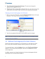
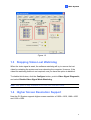
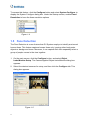
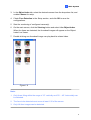
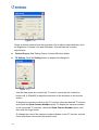
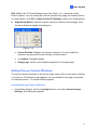
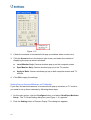
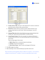
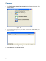
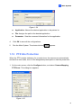
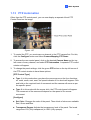
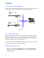
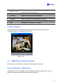
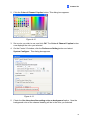
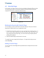
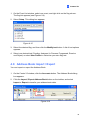
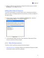
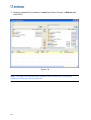
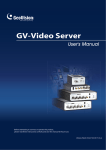
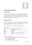
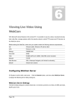
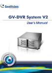
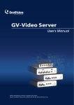
Feature Guide for
V8.1 GeoVision Surveillance System
Welcome to the Feature Guide for V8.1 GeoVision Surveillance System.
This Guide provides an overview of key features in V8.1 GV-System. It also includes
information about how the features differ from similar features in earlier versions.
Important Notice
The version 8.1 only supports the following GV video capture cards:
•
•
•
•
•
•
•
•
•
•
GV-250 All Series
GV-600(S) V3.20 and later
GV-650(S) V3.30 and later
GV-800(S) V3.30 and later
GV-1120 All Series
GV-1240 All Series
GV-1480 All Series
GV800-4A V3.10 and later
GV-2004
GV-2008
For more information on the upgrade, please visit our website at
http://www.geovision.com.tw/english/5_0.asp, or contact your dealer.
Table of Contents
1.
Main System................................................ 1
1.1
Password Expiration and Management .......................................................... 1
1.2
Different Text Alignment for Each Channel.................................................... 2
1.3
Stopping Video Lost Watchdog ........................................................................ 3
1.4
Higher Screen Resolution Support .................................................................. 3
1.5
Face Detection .................................................................................................... 4
1.6
E-mail Alert Enhancements .............................................................................. 6
1.7
System Log Enhancements .............................................................................. 6
1.8
Quad Spot Monitors Controller......................................................................... 8
1.9
Visual Automation.............................................................................................15
1.10
Virtual I/O Control .............................................................................................17
1.11
Creating Shortcuts............................................................................................17
1.12
PTZ Idle Protection...........................................................................................19
1.13
PTZ Automation ................................................................................................21
1.14
Video Server Support.......................................................................................22
1.15
POS Color Text.................................................................................................22
2.
ViewLog..................................................... 25
2.1
Backup with Direct Burn......................................................................... 25
2.2
Timeline Search..................................................................................... 26
2.3
Privacy Mask ......................................................................................... 27
2.4
Deblocking Render ................................................................................ 28
2.5
Touch Screen Support ........................................................................... 28
3.
ii
WebCam .................................................... 30
3.1
Network Port Information ....................................................................... 30
3.2
New Codec Option................................................................................. 30
3.3
3G Setting Enhancement....................................................................... 31
3.4
Enhanced Mobile Phone Applications ................................................... 32
3.5
Remote ViewLog Support ...................................................................... 34
3.6
POS Live View Support ......................................................................... 36
3.7
MultiView Enhancements....................................................................... 37
3.8
SingleView Enhancements .................................................................... 39
4.
Center V2................................................... 40
4.1
New Codec Option................................................................................. 40
4.2
Higher Screen Resolution Support ........................................................ 40
4.3
Backup Servers ..................................................................................... 41
4.4
Instant Recording and Playback ............................................................ 42
4.5
Enhanced SMS and E-Mail Alerts.......................................................... 44
4.6
Colors Added to Channel Headings....................................................... 46
4.7
Colorful Flags......................................................................................... 48
4.8
Address Book Import / Export ................................................................ 49
4.9
Alarm Report.......................................................................................... 50
4.10
Filter Enhancements .............................................................................. 51
4.11
Video Server Support............................................................................. 52
4.12
Virtual I/O Support ................................................................................. 53
5.
Dispatch Server ........................................ 54
5.1
Backup Servers ..................................................................................... 54
5.2
Colorful Flags......................................................................................... 55
5.3
Address Book Import / Export ................................................................ 56
5.4
Filter Enhancements .............................................................................. 56
5.5
Video Server Support............................................................................. 56
6.
Vital Sign Monitor (VSM).......................... 58
6.1
Backup Servers ..................................................................................... 58
6.2
Colorful Flags......................................................................................... 58
6.3
Address Book Import / Export ................................................................ 58
6.4
Enhanced SMS and E-Mail Alerts.......................................................... 58
6.5
Filter Enhancements .............................................................................. 59
iii
6.6
Notification of Insufficient Storage Space .............................................. 59
6.7
Video Server Support............................................................................. 60
6.8
Alarm Report.......................................................................................... 61
6.9
Virtual I/O Support ................................................................................. 61
7.
Control Center .......................................... 62
7.1
New Codec Option................................................................................. 62
7.2
Toolbar Enhancements.......................................................................... 62
7.3
Live View Toolbar .................................................................................. 63
7.4
Matrix View Enhancements ................................................................... 64
7.5
Remote Desktop Enhancements ........................................................... 67
7.6
E-Map Support....................................................................................... 69
7.7
Virtual I/O Support ................................................................................. 69
8.
E-Map......................................................... 70
8.1
E-Map Server......................................................................................... 70
8.2
Remote ViewLog Support ...................................................................... 72
9.
Authentication Server .............................. 73
9.1
10.
iv
Backup Servers ..................................................................................... 73
TwinDVR System...................................... 75
1 Main System
1. Main System
This chapter introduces the new features of Main System.
1.1 Password Expiration and Management
For a better password management and security, now the GV-System can “expire”
and “disable” a user’s account after a set period of time. Additionally, the system
allows users to change the given passwords.
To access this feature, click the Configure button, point to Password Setup and
select Local Account Edit. This dialog box appears.
Figure 1-1
Expire in xx day(s): The account will expire and be disabled automatically after
a set number of days. The number you set will count down automatically.
User cannot change password: The user is not allowed to change the set
password.
1
Force Password change at the first logon: The user must change the
password when logging in first time.
Disable user if do not login after xx day (s): When the user does not log in the
system after a set number of days, its account will be disabled automatically.
Changing password when logging in the GV-System
1. When you log in the GV-System, click the Change Password button in the Login
dialog box. The Change Password dialog box appears.
Figure 1-2
2. Type the new password information, and click OK to save the changes.
Note: If the user is not given the right to change password, the message Change
Password (Hint) False appears.
1.2 Different Text Alignment for Each Channel
Instead of the same text alignment for all 16 channels, you can align text overlay,
photo overlay and camera/time stamps to different positions for each channel.
To access this feature, click the Configure button, select Text Overlay Setting to
display the Text Overlay Setting dialog box, and click one Camera tab to define
various alignments.
In addition, you can even change the alignment of text and photograph while the
monitoring of POS or access control keeps on.
2
1 Main System
Figure 1-3
1.3 Stopping Video Lost Watchdog
When the video signal is weak, the software watchdog will try to recover the lost
video by restarting the system and even rebooting the computer. However, if the
video lost watchdog feature is not required, now you have the option to disable it.
To disable this feature, click the Configure button, point to Video Signal Diagnostic,
and select Disable Video Signal Weak Watchdog.
Note: This option is only available for GV-600, 650, and 800 Cards.
1.4 Higher Screen Resolution Support
Now the GV-System supports higher screen resolution of 1920 x 1200, 1680 x 1050
and 1600 x 1200.
3
To access this feature, click the Configure button and select System Configure to
display the System Configure dialog box. Under the Startup section, enable Panel
Resolution to have the three resolution options.
Figure 1-4
1.5 Face Detection
The Face Detection is a new feature that GV-System employs to identify and record
human faces. This feature captures human faces only, ignoring other body parts,
objects or background views. Moreover, it can capture each face separately when a
group of people comes in the view together.
1. On the main screen, click the Configure button, and select Object
Index/Monitor Setup. The Camera Applied Object Index/Monitor dialog box
appears.
2. Select the desired cameras for setup, and then click the Configure tab. This
dialog box appears.
Figure 1-5
4
1 Main System
3. In the Object Index tab, select the desired camera from the drop-down list, and
enable Camera for setup.
4. Check Face Detection in the Setup section, and click OK to save the
configurations.
5. Start the monitoring of configured camera(s).
6. On the main screen, click the ViewLog button and select Live Object Index.
When the faces are detected, the thumbnail images will appear on the Object
Index Live Viewer.
7. Double-clicking one thumbnail image can play back its related video.
Figure 1-6
Note:
1. Only faces tilting within the range of 15° vertically and 30° ~ 45° horizontally can
be detected.
2. The face to be detected must cover at least 1/10 of the screen.
3. Only full-face images can be detected.
5
1.6 E-mail Alert Enhancements
In addition to motion detection, now the e-mail alert with attached image will be sent
out when these events occur: Scene Change, Intruder Event, Missing Object,
Unattended Object and POS Loss Prevention.
Figure 1-7
For details, see “Sending Alerts thru E-mail Accounts,” Chapter 1, User’s Manual on
the Surveillance System Software CD.
1.7 System Log Enhancements
In this version, System Log includes the following enhancements.
New log messages
When the e-mail or SMS alerts are sent out, these activities will be recorded in
System Log for later retrieval.
Figure 1-8
6
1 Main System
Importing / Exporting Filter Configurations
In this version, you can import or export the filter configurations.
1. Click the Advanced Log Browser button on the right corner (see Figure 1-8) to
open the database.
2. On the toolbar, select the desired type of log table (Monitor, System, Login,
Counter, POS), and click the Filter button. This dialog box appears.
Figure 1-9
3. Click the Import or Export button to start the file import / export.
Note: This feature is only available in version 8.1. If you want to export the
configurations to the older version, it is not applicable.
POS Filter Enhancements
In this version, the POS Filter has been improved with three added features:
Filter the conditions in below to the selected POS table: Apply the filter
configurations to the selected POS devices.
Period between: Set the employee IDs or names for filtering.
Import / Export: Import or export the POS Filter configurations.
7
To open the POS filter, see Steps 1-2 in Importing / Exporting Filter Configurations
above.
Figure 1-10
1.8 Quad Spot Monitors Controller
The Controller integrates the GV-Multi Quad Card with TV monitor (spot monitor)
applications. It features:
•
Up to 5 TV monitors can be controlled.
•
TV Monitor 1 supports up to 16 screen divisions, and TV Monitor 2 to TV Monitor
5 support 1 and 4 divisions.
•
Different screen divisions can be set up on each monitor.
•
The channel sequence of screen divisions is user-defined.
Note: The Controller does not support the videos from GV-Video Server.
8
1 Main System
Setting up the Controller
On the main screen, click the Configure button, and select Quad Spot Monitors
Setup. This window appears.
Figure 1-11
[Video Enable] Check or uncheck the desired channels displayed on monitor screen.
[Scan Setting]
Interval: Enter the interval between the scanned pages. Set the time between 1
and 999 seconds.
Scan by: Select Auto to scan the channels automatically or Manual to scan at
your speed.
[Video Format] Select NTSC or PAL. The video standard may vary from country to
country. Check the video standard in your country first.
[Setting]
Video Attribute: Click the Setting button to display this dialog box.
9
Figure 1-12
Select a desired camera from the drop-down list to adjust image attributes, such
as Brightness, Contrast, Hue and Saturation. Use the slide bar to make
adjustments.
Camera Popup: See Setting Pop-up Camera Windows below.
TV Setting: Click the Setting button to display this dialog box.
Figure 1-13
Use the drop-down list to select the TV monitor, and press the 4 direction
buttons (U, L, R and D) to adjust the positions of the divisions on the monitor
screen.
To display the camera number on the TV monitor, select the desired TV monitor,
and check the Show Camera Number option. To display the camera numbers
on all connected TV monitors, check the Show Camera Number option, and
then click the finger button.
To change the color of the camera number indicator on the TV monitor, use the
Color drop-down list to select the desired color.
10
1 Main System
[DIV 1-16] In the TV Quad Setting window (see Figure 1-11), there are screen
division options. You can modify the channel sequence by typing the number directly
on each division. Click OK or Apply Current TV Setting to apply your configurations.
Right Arrow Button: Sets the channel sequence of each scanned page. Click
the arrow button to display this dialog box.
Figure 1-14
Screen Division: Displays the channel sequence. You can modify the
sequence by typing the number directly on each division.
< > buttons: Navigates pages.
Empty page: Clears up the channel sequence on the open page.
Setting Pop-up Camera Windows
The pop-up camera windows on the screen notify users of the current event, whether
it is motion or I/O devices being triggered. You can decide to have pop-up cameras
on computer screen, TV monitor or both together.
Activating Pop-up Camera Windows
1. On the Main System, click the Configure button, and select Camera Popup
Settings. This dialog box appears.
11
Figure 1-15
2. Check the cameras to be alarmed with pop-up windows when events occur.
3. Click the Arrow button in the bottom right corner, and select the method of
displaying the pop-up camera windows.
Local Monitor Only: Camera windows pop up on the computer screen.
Spot Monitor Only: Camera windows pop up on the TV monitor.
Apply to Both: Camera windows pop up on both computer screen and TV
monitor.
4. Click OK to apply the settings.
Setting Pop-up Camera Windows on TV Monitor
If you want the selected cameras to be alerted with pop-up windows on TV monitor,
you need to set up those cameras by following these steps.
1. On the main screen, click the Configure button, and select Quad Spot Monitors
Setup. The TV Quad Setting dialog box (see Figure 1-11) appears.
2. Click the Setting button of Camera Popup. This dialog box appears.
12
1 Main System
Figure 1-16
TV tabs (TV1 to TV5): Click the TV tab to select the TV monitor on which the
selected camera is alarmed with pop-up windows.
Dwell Time: Specify how long a pop-up camera window remains on the
monitor screen when an event occurs. Set the time between 1 and 120
seconds.
Interrupt Time: Specify the interval between pop-up camera windows when
events occur. Set the time interval between 1 and 60 seconds.
Invoke Popup Camera: Select the camera(s) to be alarmed with pop-up
windows when events occur, and use the drop-down list to select the type of
alert events.
There are three types of alert events:
Motion Only: Motion is detected during the monitoring.
I/O Only: I/O devices are triggered.
Both Invoke Popup: Alerts of motion and triggered I/O devices.
5. Click OK to apply the settings.
6. Start monitoring so that camera windows pop up when events occur.
Tip: All cameras can be repetitively setup on different TV monitors. If one camera is
selected on more than one TV monitors, it can be set with different alert events.
13
Displaying TV Quad Panel on the Main Screen
On the Main System, click the TV-Out button
. This panel appears.
1
5
6
2
8
7
3
9
4
10
Figure 1-17
The controls on the TV Quad Panel:
No. Name
Description
1
Monitor
2
Scan
3
Screen Division
4
5
6
7
8
9
Channel Menu
Exit
Previous Page
Next Page
Settings
Switch
10
Zoom Esc
Selects the monitor to be controlled.
Automatically or manually rotates channels, and stops
rotation.
Sets screen divisions. Only TV 1 can support screen
divisions up to 16, and TV 2 to TV 5 supports 1 or 4 screen
divisions.
Displays the desired channel for single view.
Closes the TV Quad Panel.
Scans the previous page.
Scans the next page.
Displays the TV Quad Setting window.
Displays or hides the channel menu.
After single view, click this button to return to the first
scanned page or return to the last channel when the screen
division is set to 1.
Note: If the DSP Spot Monitor function is enabled at the same time with the Quad
Spot Monitors, the TV-Out button has two options: Spot Monitor Panel and TV Quad
Panel. Select the desired panel to be displayed on the screen.
14
1 Main System
Running the Quad Spot Monitors Controller Alone
Without starting the Main System, the Quad Spot Monitors Controller can be run
independently. Find the QuadTV.exe in the GV folder and double-click it. The TV
Quad Panel will appear (see Figure 1-17).
1.9 Visual Automation
The Visual Automation helps you automate any electronic device by triggering the
connected output. You can intuitively click on the image of the electronic device to
change its current status, e.g. light ON.
Setting Up Visual Automation
1. On the main screen, click the Configure button, and select Visual Automation
Setting. This dialog box appears.
Figure 1-18
2. Select the desired camera from the drop-down list, and check Enable.
3. Drag the area on the image of the desired device. This dialog box appears.
15
Figure 1-19
4. Select the connected module and output device. In the Note field, type a note to
help you manage the device. Click OK to save the configurations.
5. To change the frame color of the set area, click the Set Color button.
6. To emboss the set area, check the Float Up option; or keep them flat by checking
the Normal option.
Using Visual Automation
1. On the main screen, click on the desired Camera Name on the top left corner of
every channel, and select I/O Automation. This separate View appears.
Figure 1-20
2. Click on the image of the desired electronic device to change its current status.
3. To change the style of the set areas, right-click the green I/O icon on the Visual
Automation View to have these options:
Show All: Displays all set areas.
Rect Float: Embosses all set areas.
Set Color: Changes the frame color of all set areas.
16
1 Main System
1.10 Virtual I/O Control
In this version, the GV-System can work with the GV-Video Server and GV-Wiegand
Capture, and the integration allows the GV-System to control their connected I/O
devices respectively.
On the main screen, click the Configure button, select I/O Application, and then
select Virtual I/O Setting. This dialog box appears. The I/O device settings are
similar to those of the Main System. For details, see “I/O Applications”, Chapter 2,
User’s Manual on the Surveillance System Software CD.
Figure 1-21
1.11 Creating Shortcuts
You can create up to 20 shortcuts on the main screen to a program or file.
17
1.
Run Fast Backup & Restore Main System from the Windows Start menu. This
window appears.
Figure 1-22
2.
Click the Select Skin Style button, point to DVR, and select User Define Setting. This
dialog box appears.
Figure 1-23
3. Click the Add button. This dialog box appears.
18
1 Main System
Figure 1-24
Application: Names the desired application to be pointed to.
File: Assigns the path to the desired application.
Parameter: Sets the command information for the application.
4.
Click OK to save all the configurations.
5.
Run the Main System. The shortcut button
appears.
1.12 PTZ Idle Protection
When the PTZ remains stationary for a certain time, the camera can automatically
activate the auto mode, move to the designated preset point or start the preset tour.
1. On the main screen, click the Configure button, and select Camera Mapping
PTZ Dome. This dialog box appears.
Figure 1-25
19
2. Select the desired camera from the Device drop-down list, and check PTZ
Inactivity.
3. Set the idle time after which to start the protection mode.
4. Select Auto, Preset or Multi Position Tour as protection mode.
Setting Multi Position Tour
You can create a PTZ tour with up to 16 preset points
1. Select Multi Position Tour on the Camera Mapping Setup dialog box (see Figure
1-25), and click the Setting button. This dialog box appears.
Figure 1-26
2. Select a Preset as a start point.
3. Set the Dwell Time that the PTZ will remain in a preset.
4. Click Add and repeat Steps 2-3 to build more points in the tour.
20
1 Main System
1.13 PTZ Automation
Other than the PTZ control panel, you can now display a separate Visual PTZ
Control Panel on the image.
Figure 1-27
1. To control the PTZ, you must map one channel to the PTZ camera first. For this,
click the Configure button and select Camera Mapping PTZ Dome.
2. To access the new control panel, click on the desired Camera Name on the top
left corner of every channel, and select PTZ Automation. A separate PTZ control
window will appear.
3. To change the panel settings, click the green PTZ button on the top left corner of
the PTZ control window to have these options:
[PTZ Control Type]
Type 1: In this mode when you place the mouse arrow on the four directions,
ex. north, south, east, west, the speed indicator of five levels will appear. Click
and hold on the required level of movement and the camera will move as per
the specific speed.
Type 2: In this mode with the mouse click, the PTZ control panel will appear.
The movement of the camera will depend on the speed of the mouse
movement.
[Configure]
Set Color: Changes the color of the panel. Three kinds of colors are available:
Red, Green and Blue.
Transparent Degree: Adjusts the transparency level of the panel. Ten levels
range from 10% (fully transparent) to 100% (fully opaque).
21
1.14 Video Server Support
The GV-System can monitor and manage the cameras and I/O devices connected to
the GV-Video Server. For details, see GV-Video Server User’s Manual.
X2
TCP/ IP
X2
GV-Video Server
Video Data
GV-System with
16-channel Display
X2
X2
GV-Video Server
Figure 1-28
1.15 POS Color Text
The POS Color Text feature allows you to use different colors and time periods to
identify any desired transaction items. When the transaction item is identified, the
feature can trigger the alarm and send out the alert message. The identification is
recorded in the System Log for later retrieval as well.
For example, if the liquor is prohibited from being sold in the midnight, a seller can
use this feature to prevent from any unintentional sale.
Setting Up POS Color Text
1.
22
On the main screen, click the Configure button, point to POS Application
Setting, and select POS Filed Filter Setup. The POS Capture Data Setting
dialog box appears.
1 Main System
2.
Click the New button. This dialog box appears.
Figure 1-29
[Key Word] Type the text to be identified in the transaction data. The keyword
setting is case sensitive.
[Color] Specify a color to identify the defined text.
[only work between] Specify the time period to identify the defined text in the
transaction data.
3.
To trigger an alarm when the defined text is detected during the transaction, click
the Loss Prevention Setting button in the POS Capture Data Setting dialog box.
This dialog box appears.
Figure 1-30
23
Enable Alarm: Check this item to send out an alarm when the identified text
is detected.
Alarm Output: Check this item and use the drop-down lists to select the
connected module and output device.
Alert Message: Type the message for the E-mail or SMS alerts to be sent out
when the alarm is triggered.
4.
Click OK to save the above settings.
5.
When the defined text is identified in the transaction data, the identification
appears not only on the Main Screen but also on the POS Live View window. It is
also recorded in the System Log.
Figure 1-31
Note: You can set the maximum of 32 keywords for identification.
24
2
ViewLog
2. ViewLog
This chapter introduces the new features of ViewLog.
2.1 Backup with Direct Burn
Using Nero software, this version allows you to directly burn the files onto CD/DVD
without the hassle of calling up the software and making the copy and paste.
This direct-burn feature supports CD, DVD and blu-ray media. For CD and DVD
burning, Nero version 6.6.0.1 or later is required to install in your PC. For blu-ray, you
need at least Nero version 7.0.
1. Click the Backup button
. This dialog box appears.
If the required Nero version has been installed in your computer, you should see
the Nero mark
in the Media Information section.
Figure 2-1
2. Click the Add Time Frame button to define a time period for backup.
3. Click OK on this Backup dialog box. The system will burn the files onto CD/DVD
directly.
25
2.2 Timeline Search
In addition to Date Tree, this version provides you another graphical search method
called “Timeline” to locate your desired events within a set period of time.
1. Select the desired view mode for playback by clicking the View Mode button. If
you select Single View, assign a camera from the Camera drop-down list.
2. Click the Advanced button
, and select Timeline Search. This window
appears.
Figure 2-2
3. Select a date from the calendar.
•
The date with recorded events is displayed in GREEN color.
•
On the right panel, the BLUE blocks indicate which camera has recorded
events on the selected date and at which hour.
4. Move the mouse pointer on the desired BLUE block, and right-click it to have the
sub Timelines of hour mode and minute mode. Three types of Timeline modes
are available:
Change to day mode: The default mode displaying at which hour the events
have been recorded.
Change to hour mode: Opens the sub Timeline displaying at which minute
the events have been recorded.
Change to minute mode: Opens the sub Timeline displaying at which second
the events have been recorded.
5. Click on the BLUE block of the desired time, and then click Play or Rewind for
playback.
26
2
ViewLog
2.3 Privacy Mask
The Privacy Mask, which was earlier only available at the Main System, is now
added to ViewLog in case you forget to set the Privacy Mask at the Main System or
you need to add more Privacy Masks onto the video for special requirements.
1. Click the Save as AVI button. This dialog box appears.
Figure 2-4
2. In the Export with New Privacy Mask Region(s) section, select Un-recoverable
and/or Recoverable.
Un-recoverable: The block-out area(s) in the recorded clips cannot be
retrieved.
Recoverable: The block-out area(s) is retrievable with password protection.
3. Drag the area(s) where you want to block out on the image. You will be prompted
to click Add to save the setting.
Using a valid ID and Password, you can retrieve the recoverable block-out area(s) in
the exported file. For details on the Privacy Mask, see “Privacy Mask Protection”,
Chapter 1, User’s Manual on the Surveillance System Software CD.
27
2.4
Deblocking Render
The Deblocking Render can remove the block-like artifacts from low-quality and
highly compressed video, greatly increasing the overall quality of video.
To enable this feature, click the Setting button to display the System Configuration
dialog box, click the Display tab, and check Apply deblocking render (single view
only).
Figure 2-5
2.5 Touch Screen Support
By the touch of a finger, the touch screen panel allows you to change screen
divisions, switch to full screen and close the ViewLog screen.
1. Click the Tools button, point to Tool Kit, select Touch Screen Panel, and click
Panel Setup. This dialog box appears.
Figure2-6
28
2
ViewLog
2. Click Active to have these options:
Active when enter Full-Screen Mode only: Launches automatically the
panel when the full screen view is applied.
Always Active: Always displays on the ViewLog screen.
Layout: Select a vertical or horizontal panel.
3. Click OK for the above settings.
4. To active the panel, click the Tools button, point to Tool Kit, select Touch Screen
Panel, and click Panel Active.
5. At the upper left corner of the screen, an information window indicating date, time
and storage space will appear. Right-click it to open this touch panel.
Figure 2-7
29
3. WebCam
This chapter introduces the new features of WebCam.
3.1 Network Port Information
In this version, an easy option is provided to view and manage all network ports of
the GV remote applications.
On the main screen, click the Network button, and select Network Port Information.
This dialog box appears.
1 2 3
Figure 3-1
The controls on the Port Settings:
No. Name
Description
1
Modify
Changes the port settings.
2
Save
3
Port Mapping
Saves the port settings.
Employs UPnP technology (Universal Plug and Play) to
allow automatic port configuration to the router.
3.2 New Codec Option
This version provides one more video codec option Geo Mpeg4 ASP, offering a
smaller compressed file size than previous Geo Mpeg4.
30
3
WebCam
To select the codec, on the main screen, click the Network button, select WebCam
Server, and click the Video tab.
Figure 3-2
3.3 3G Setting Enhancement
To enhance the security of the WebCam server during the connection with the 3G
supported mobiles, the number of RTP/RTCP/UDP ports for use is now limited to 80.
To set the range of RTP/RTCP/UDP ports, on the main screen, click the Network
button, select WebCam Server, and click the 3GPP tab.
Figure 3-3
31
3.4 Enhanced Mobile Phone Applications
This version includes several new features in the GV mobile phone applications. The
three major features are the change of video format, an independent mobile server
provided for configurations, and the third version of SSView exclusively designed for
Nokia S60 2nd platform.
Viewing Applications
New Features
GView Version 2
for PDA
Video streaming, GV-Video Server support, PTZ
control, output control, Remote Playback (RPB),
etc.
MSView Version 2
for Microsoft Smartphone
Video streaming, GV-Video Server support, PTZ
control, output control, Remote Playback (RPB),
etc.
SSView Version 2
for Symbian Smartphone
PTZ control, output control, etc.
SSView Version 3
For Nokia S60 2nd
Video Streaming, Remote Playback (RPB), PTZ
control, output control, etc.
Change of Video Format
Instead of receiving JPEG format images, now the users of GView (for PDA) and MS
View (for Microsoft Smartphone) will experience live video streaming, which offers
them better video quality.
rd
The 3 version of SSView
The third version of SSView is exclusively designed for Nokia S60 2nd edition
software. SSView Version 3 provides the features of video streaming, remote
playback, PTZ control and output control. For the device model based on S60 2nd
edition software, please consult Nokia’s website:
http://www.forum.nokia.com/devices/matrix_all_1.html
32
3
WebCam
Mobile Server
A separate Mobile Server is provided to integrate the configurations of the GV mobile
phone applications.
1. On the main screen, click the Network button, select WebCam Server, and click
the Mobile tab. This dialog box appears.
Figure 3-4
2. Check the box in the up left corner to enable this function.
Port: The default communication port is 8866.
Rpb port: This port is used for remote playback feature. The default value is
5511.
Max. connection: Specify the number of users that can connect to this
server. Set the number between 1 and 20.
Max. FPS: Specify the number of frames to be transferred per second.
For details on the mobile phone applications, see “Remote Viewing with PDA” and
“Remote Viewing with Mobile Phone,” Chapter 6, User’s Manual on the Surveillance
System Software CD.
33
3.5 Remote ViewLog Support
Through WebCam Server, you can remotely play back the recorded files by using the
video player ViewLog. This provides you another playback option other than the
Remote Playback application.
1. The GV-System needs to allow the remote access first. Click the Network button,
select WebCam Server, and enable Run ViewLog Server.
Figure 3-5
2. At the local PC, open a browser, and type the address of the remote GV-System.
This page appears.
Figure 3-6
34
3
WebCam
3. Select Remote Play Back / ViewLog, and click the Submit button. This page
appears.
Figure 3-7
4. Select ViewLog, select the desired screen resolution, and click the Submit
button. This dialog box appears.
Figure 3-8
5. Type the IP Address, ID and Password of the remote GV-System. Keep the
default port as 5552, or modify it if necessary.
6. In the Host Type field, select DVR.
7. Click the Connect button.
When the connection is established, you will see the video player ViewLog appears
on the screen. Then you can access all ViewLog features for playback.
35
3.6 POS Live View Support
Through WebCam Server, it is now possible to monitor the surveillance sites of POS
or access control systems. You can view not only live video, but also transaction data
or cardholder information.
1. Open a browser, and type the address of the remote GV-System. The
Compression Selection page appears (see Figure 3-6).
2. Select POS Live View, and click the Submit button. The remote POS Live View
window appears.
3. Click the Play button, and type the valid user name and password to start the
connection.
The Remote POS Live View Window
1
2
3
9
8
7
6
5
4
Figure 3-9
The controls on the remote Post Live View window:
No. Name
Description
1
Option
2
Change Camera
Brings up these options: Show Camera Name and Enable
DirectDraw.
Selects the desired camera for display.
36
3
3
4
5
6
7
8
9
POS Live View
Zoom
File Save
Change Quality
Snapshot
Stop
Play
WebCam
Brings up these options: Next Transaction, Previous
Transaction and Freeze Event.
Switches to full screen view.
Saves live video in the local computer.
Adjusts video quality in 4 levels.
Takes a snapshot of the displayed live video.
Terminates the connection to the remote GV-System.
Connects to the remote GV-System.
Instant Playback
You can play back the video instantly by double-clicking on any suspicious
transaction items or cardholder’s information.
Figure 3-10
3.7 MultiView Enhancements
In this version, the MultiView includes the following new features.
Easy Installation of MultiView
The MulitView is now included in the Surveillance System Software CD. You can
install the program easily without accessing the Internet.
37
1. Insert the Surveillance System Software CD to your computer. It will automatically
run and a window appears.
2. Select the Install V 8.1.0.0 System item.
3. Select MultiView, and follow the on-screen instructions.
When the program is installed successfully, a shortcut of the MultiView will be created
on the desktop.
Higher Screen Resolution Support
The MulitView supports higher screen resolution of 1920 x 1200, 1680 x 1050 and
1600 x 1200.
Figure 3-11
Remote ViewLog Support
More than simply playing back recorded video/audio files, the added Remote
ViewLog function allows you to have full access to the ViewLog features of the
connected GV-System.
Note: To use the Remote ViewLog for the first time, you need to install the Remote
ViewLog components on the local PC. Install the components from the Surveillance
System Software CD, or by following the steps 2-4 described in 3.5 Remote ViewLog
Support .
38
3
WebCam
1. On the MultiView window, click the ViewLog button
. The Connect to
Remote ViewLog Service dialog box appears (see Figure 3-8).
2. Type the IP Address, ID and Password of the remote GV-System. Keep the
default port as 5552, or modify it if necessary.
3. In the Host Type field, select DVR.
4. Click the Connect button.
When the connection is established, you will see the video player ViewLog appears
on the screen. Then you can access all ViewLog features for playback
3.8 SingleView Enhancements
The SingleView supports the two new features in the Main System: Visual
Automation of I/O and PTZ.
Visual Automation
You can remotely change the current status of the electronic device by clicking on its
image, as well as managing the settings of Visual Automation.
This feature is only available when the Visual Automation is set ahead in the Main
System. To access this feature, on the SingleView window, click the I/O Control
button, and select Visual Automation. For details on using Visual Automation, see
1.9 Visual Automation.
Visual PTZ
Other than the PTZ control panel, now you can display a Visual PTZ Control Panel
on the image.
To access this feature, on the SingleView window, click the PTZ Control button and
select Visual PTZ. For details on using the new control panel, see 1.13 PTZ
Automation.
39
4. Center V2
This chapter introduces the new features of Center V2.
4.1 New Codec Option
This version provides one more video codec option Geo Mpeg4 ASP, offering a
smaller compressed file size than previous Geo Mpeg4.
To select the codec, on the main screen, click the Network button, select Connect
to Center V2, and click the Advance… button.
Figure 4-1
4.2 Higher Screen Resolution Support
Center V2 supports higher screen resolution of 1600 x 1200, 1680 x 1050 and 1920 x
1200.
40
4
Center V2
1. On the Center V2 window, click the Preference Settings button, select System
Configure, and click the Layout tab. This dialog box appears.
Figure 4-2
2.
Select the desired resolution from the Main Panel Resolution drop-down list.
The new resolution is effective after next login.
4.3 Backup Servers
You can configure up to two backup servers in case of the primary Center V2 server
failure. Whenever the primary fails, the backup server takes over the connection from
subscribers, providing uninterrupted monitoring services.
1. Import the subscriber accounts from the primary server to the backup server. For
details on the Import feature, see 4.8 Address Book Import / Export.
2. On the Center V2 window, click the Preference Settings button, and select
Automatic Failover Support. This dialog box appears.
41
Figure 4-3
3. Click the Add button to add one server. This dialog box appears.
Figure 4-4
4. Type the IP Address of the backup server. Keep the default port settings or modify
them if necessary.
5. Click OK.
Note: Once the primary server is ready to resume the services, it is required to close
the backup server so the connection from subscribers can move back to the primary.
4.4 Instant Recording and Playback
Now you enable live view in a more convenient way, and start and stop recording
instantly to any live-view camera.
42
4
Center V2
Enabling Live View
•
You can enable live view of any camera by right-clicking it in the subscriber’s list,
and then selecting Live View.
Figure 4-5
•
When a subscriber is in focus, you can enable live view to all its cameras. Click a
subscriber in the list and select Focus on this subscriber only. When the
subscriber is in focus, click the subscriber again and then select View All
Cameras (Live). All cameras of this focused subscriber display live view.
Figure 4-6
Recording and Playing Back Instantly
•
When a camera is enabled for live view, you can start and stop recording by
clicking the
•
button on the channel heading.
As soon as you stop recording, you can double-click the attachment of the event
in the Event List for instant playback.
43
4.5 Enhanced SMS and E-Mail Alerts
In this version, you can set time intervals between each e-mail and SMS message
when events occur. Moreover, you can schedule the e-mails and SMS messages to
be sent out within the set period of time.
Setting Alert Interval for E-Mails
1. On the Center V2 window, click the Preference Setting button, and select E-mail
Setup. This dialog box appears.
Figure 4-7
2. In the Alert Setup section, set the interval between 0 and 60 minutes.
Setting Alert Intervals for SMS
1. On the Center V2 window, click the SMS button, select SMS Setup and click the
SMS Option tab. This dialog box appears.
Figure 4-8
44
4
Center V2
2. In the SMS Alert Setup section, set the interval between 0 and 1440 minutes.
Scheduling Alert Notification
In this version, both e-mail and SMS notifications can be scheduled ahead. E-mails
and SMS messages will be sent out within the scheduled period of time.
1. On the Center V2 window, click the Accounts button. The Address Book window
appears.
2. Highlight one subscriber, and click the Subscriber Schedule button. The
Schedule window appears.
3. On the Schedule window, double-click an established plan. This Plan window
appears.
Figure 4-9
4. Click the Advanced Setting button
. The Advanced Setting dialog box
appears.
5. Expand the Notification folder, and check or uncheck the alert methods to be
scheduled.
6. On the Plan window, click the Notification button, drag the mouse over SMS and
/ or E-mail timelines to define the Start time and End time to send out alerts.
45
Note: Once you enable the schedule function, you will not be notified when events
occur outside the scheduled period of time.
4.6 Colors Added to Channel Headings
For easy identification, the channel headings can be as colorful as you wish. In
addition to the change of color and font of the channel headings, its background color
can be customized as well.
Channel Heading
Figure 4-10
1. On Center V2 window, click the Accounts button, highlight a subscriber, and click
the Subscriber Setting button on the toolbar. This dialog box appears.
Figure 4-11
46
4
Center V2
2. Click the Color of Channel Caption button. This dialog box appears.
Figure 4-12
3. Set a color you wish to use, and click OK. The Color of Channel Caption button
now displays the color you selected.
4. On the Center V2 window, click the Preference Setting button and select
System Configure. This dialog box appears.
Figure 4-13
5. Check the Use the subscriber setting color as background option. Now the
background color of the channel heading will be in the color you selected.
47
4.7 Colorful Flags
In this version, the flags of various colors are provided to distinguish different events.
You will find them useful not only when browsing in the Event List but also when
using the Filter function to search the desired events.
Figure 4-14
Marking the Events with Colorful Flags
You can flag any events in the Event List for later reference. There are 6 kinds of
flags and one check mark for you to signify the events.
1. On the Event List window, select one event, and right-click on the flag column. A
list of 6 kinds of flags in different colors (Red Flag, Blue Flag, Yellow Flag, Green
Flag, Orange Flag and Purple Flag), one check mark (Flag Complete) and two
setting options appears.
2. Select the desired flag or check mark for the event.
To unmark the events, simply click the flag icon. Or right-click the flag icon and
select Clear Flag.
Editing Colorful Flags
You can name the colorful flags with the provided texts or change the texts to meet
your needs.
48
4
Center V2
1. On the Event List window, select one event, and right-click on the flag column.
The flag list appears (see Figure 4-14).
2. Select Setup. This dialog box appears.
Figure 4-15
3. Select the desired flag, and then click the Modify text button. A list of text options
appears.
4. Select one desired text (Pending, Assigned, In Process, Progressed, Resolve
and Reject) or select User Define to customize your own flag text.
4.8 Address Book Import / Export
You can import or export the Address Book.
1. On the Center V2 window, click the Accounts button. The Address Book dialog
box appears.
2. Click the Import / Export Address Book button on the toolbar, and select
Import or Export to transfer your address book data.
Figure 4-16
49
4.9 Alarm Report
For every event, the Center V2 operator can generate a report to evaluate certain
conditions.
Creating an Alarm Report
1. In the Event List window, select an event and click on the report column. This
dialog box appears.
Figure 4-17
2. In the Reporter field, type the name, and click Start to begin the report.
3. There are 6 report categories. Click the desired category tab(s) for report.
Event Type: Select a type to classify the event.
Description: Select a description for the event.
Notification: Select the authority being notified, and enter the notified time.
Arrival: The button becomes available after you select a notified authority.
Enter the arrival time of the authority.
Measures: Select the measure taken to deal with the event.
Other: The button is available only when the e-mail and /or SMS alert are
configured.
50
4
Center V2
4. When you finish the report and will not change the contents anymore, click the
End Report. Or click Save to edit later.
Editing Alarm Report Categories
The items in each category of the Alarm Report can be customized and edited to
meet your needs. The changes made here are permanent, and will be available for
the report creation.
1. On the Center V2 window, click the Preference Settings button, and select
Customize Alarm Report. This dialog box appears.
Figure 4-18
2. Click the desired category tab (Event Type, Description, Measurement Taken,
Patrol) to make the necessary changes.
4.10 Filter Enhancements
The Filter in Event Log Browser includes the two new features.
•
New Search Criteria. The flags of different colors and Alarm Reports are added
to the search criteria in the Event Log Browser.
51
Figure 4-19
•
Importing / Exporting Filter Settings. You can import or export the Filter
settings. To access this feature, click the Import or Export button in the Filter
dialog box (see Figure 4-19).
4.11 Video Server Support
The Center V2 can monitor and manage the cameras connected to the GV-Video
Server. For details, see GV-Video Server User’s Manual.
X2
TCP/ IP
X2
GV-Video Server
Video Data
Text Data
X2
Center V2
X2
GV-Video Server
Figure 4-20
52
4
Center V2
To enable connecting to the GV-Video Server, click the Preference Settings button,
select System Configure to display the Preference dialog box, click the Network tab,
and check Accept the Connection of Video Server. Keep default port as 5551, or
modify it to match the Center V2 port on the GV-Video Server.
Figure 4-21
4.12 Virtual I/O Support
If subscribers enable the Virtual I/O function to control the I/O devices connected to
GV-Video Server and GV-Wiegand Capture, the Center V2 can also control these
added I/O devices during the connection. For detail, see 1.10 Virtual I/O Control.
53
5. Dispatch Server
This chapter introduces the new features of Dispatch Server.
5.1 Backup Servers
You can configure up to two backup servers in case of the primary server failure.
Whenever the primary fails, the backup server takes over the connection from
subscribers, providing uninterrupted services.
1. Import the subscribers’ accounts from the primary server to the backup server.
For details on the Import feature, see 5.3 Address Book Import / Export.
2. On the Dispatch Server window, click the Server Setting button. The Server
Setting dialog box appears.
3. Check the Automatic Failover Support option. The Automatic Failover Support
dialog box appears.
Figure 5-1
4. Click the Add button. The Setting dialog box (see Figure 5-2) appears.
5. Type the IP address of the backup server, and change the default port settings if
necessary.
6. Type the Identification Code matching to that in CenterV2 Identification Setting
(see Figure 5-2). If the information is inconsistent, the connection to the backup
server cannot be established.
54
5
Dispatch Server
Type the same Code here
Figure 5-2
Note: Once the primary server is ready to resume the services, it is required to close
the backup server so the connection from subscribers can move back to the primary.
5.2 Colorful Flags
In this version, the flags of various colors are provided to distinguish different events.
You will find them useful not only when browsing in the Real-Time CenterV2 Event
List window but also when using the Filter function to search the desired events.
Figure 5-3
This feature is the same as that of the Center V2. For details, see 4.7 Colorful Flags.
55
5.3 Address Book Import / Export
You can import or export the Address Book.
This feature is the same as that of the Center V2. For details, see 4.8 Address Book
Import / Export.
5.4 Filter Enhancements
In this version, the Filter in Event Log Browser includes the two new features: new
search criteria and importing / exporting Filter settings
These features are the same as those of the Center V2. For details, see 4.10 Filter
Enhancements.
5.5 Video Server Support
The Dispatch Server can manage the videos connected to GV-Video Server, and
distribute them to the Center V2. For details, see GV-Video Server User’s Manual.
X2
TCP/ IP
X2
GV-Video Server
Center V2
Video Data
Text Data
X2
Dispatch Server
X2
GV-Video Server
Center V2
Figure 5-4
56
5
Dispatch Server
To enable connecting to the GV-Video Server, click the Server Setting button on the
toolbar, and enable Allow Video Server Login as Subscriber from Port. Keep the
default port as 5551, or modify it to match the Center V2 port on the GV-Video Server.
Figure 5-5
57
6. Vital Sign Monitor (VSM)
This chapter introduces the new features of Vital Sign Monitor (VSM).
6.1 Backup Servers
You can configure up to two backup servers in case of the primary VSM server
failure. Whenever the primary fails, the backup server takes over the connection from
subscribers, providing uninterrupted monitoring services.
To access this feature, on the VSM window menu, click Service, and select
Automatic Failover Support. This feature is the same as Center V2’s. For details on
setup, see 4.3 Backup Servers.
6.2 Colorful Flags
In this version, the flags of various colors are provided to distinguish different events.
You will find them useful not only when browsing in the Event List but also when
using the Filter function to search the desired events.
This feature is the same as Center V2’s. For details, see 4.7 Colorful Flags.
6.3 Address Book Import / Export
You can import or export the Address Book.
This feature is the same as Center V2’s. For details, see 4.8 Address Book Import /
Export.
6.4 Enhanced SMS and E-Mail Alerts
In this version, you can set time intervals between each e-mail and SMS message
when events occur. Moreover, you can schedule the e-mails and SMS messages to
be sent out within the set period of time.
This feature is the same as Center V2’s. For details, see 4.5 Enhanced SMS and EMail Alerts.
58
6
Vital Sign Monitor
6.5 Filter Enhancements
In this version, the Filter in Event Log Browser includes the two new features: new
search criteria and Importing / Exporting Filter settings
These features are the same as those of the Center V2. For details, see 4.10 Filter
Enhancements.
6.6 Notification of Insufficient Storage Space
When the subscriber’s storage space is insufficient, the VSM operator can get
notified.
1. In the Main System, click the Network button, and select Connect to VSM. The
Connect to the Vital Sign Monitor dialog box appears.
2. Click the Advance button, and then select the System Information tab. This
dialog box appears.
Figure 6-1
3. Check the Notify Vital Sign Monitor when the total amount of free storage
space is lower than ( ) GB option, and set the space limit. The space limit is 1
GB at least.
59
6.7 Video Server Support
The VSM can monitor and manage the cameras connected to the GV-Video Server.
For details, see GV-Video Server User’s Manual.
X2
TCP/ IP
X2
GV-Video Server
Text Data
X2
VSM
X2
GV-Video Server
Figure 6-2
To set the appropriate port connecting to the GV-Video Server, click Configure on
the window menu, and select System Configure to display this dialog box. Under
the Connective Port for Video Server item, keep the default port 5609, or modify it to
match the VSM port on the GV-Video Server.
Figure 6-3
60
6
Vital Sign Monitor
6.8 Alarm Report
For every event, the VSM operator can generate a report to evaluate certain
conditions.
This function is the same as that of the Center V2. For details, see 4.9 Alarm Report.
6.9 Virtual I/O Support
If subscribers enable the Virtual I/O function to control I/O devices connected to GVVideo Server and GV-Wiegand Capture, the VSM can also control these added I/O
devices during the connection.
For details, see 1.10 Virtual I/O Control.
61
7. Control Center
This chapter introduces the new features of Control Center.
7.1 New Codec Option
This version provides one more video codec option Geo Mpeg4 ASP, offering a
smaller compressed file size than previous Geo Mpeg4.
To access the codec, open the Control Center Server window, click Configure on
the menu bar, and then select Network Settings.
Figure 7-1
7.2 Toolbar Enhancements
The Control Center toolbar includes the two features:
•
It automatically minimizes to the taskbar when the Control Center is started.
•
It always stays on the top of all windows.
To access the two features, on the Control Center toolbar, click the Configure button,
and select System Configure. Check Minimum when startup to minimize the
toolbar, or Always on Top to keep the toolbar on the top of other windows.
62
7 Control Center
Figure 7-2
7.3 Live View Toolbar
A toolbar is added to the Live View window, providing more functions to manage the
live video.
To access this feature, right-click any camera on the Host List or Group List, and
select Live View. Or click the Camera Information button
then select Live View. The Live View window appears.
1
2
3
4
5
6
7
on the toolbar and
8
Figure 7-3
63
The controls on the Live View window:
No. Name
Description
1
Change Size
Changes the size of the Live View window. The size
corresponds to the video resolution set at the DVR site. The
size choices are only available when the video resolution is
higher than 320 x 240.
2
Audio
Starts this function to receive the sounds.
3
Microphone
Enables speaking to the remote DVR.
4
Setting
Changes the audio and video setting of live view.
5
PTZ
Activates the PTZ control by selecting PTZ Panel or PTZ
Automation.
Start this function, and right-click on the window to display
the control menu. This button is only available when the
Visual Automation is set at the DVR site.
Show all: Displays all alert regions.
Rect Float: Embosses all alert regions.
Set Color: Sets the frame color of alert regions.
6
Visual Automation
7
Snapshot
Takes the snapshot of the displayed live video.
8
Zoom
Enlarges the video by selecting 1.0x, 2.0x and 3.0x.
7.4 Matrix View Enhancements
In this version, the Multi View includes the following new features.
Higher screen resolution
The Matrix View supports higher screen resolution of 1280 x 1024, 1600 x 1200,
1680 x 1050 and 1920 x 1200.
Due to support for higher screen resolution, the maximum number of channels Matrix
View provides is increased from 64 to 96. Each screen resolution provides the
different number of channels as listed below:
•
•
•
64
1280 x 1024 and 1600 x 1200 support up to 64 channels.
1680 x 1050 supports up to 80 channels.
1920 x 1200 supports up to 96 channels.
7 Control Center
To change the screen resolution, click the Configure button on the Control Center
toolbar, select System Configure and click the Matrix tab. The four Matrix windows
can be set at different screen resolutions.
Figure 7-4
PTZ Control
The PTZ button is added to the toolbar for PTZ control. Click this button to display
the PTZ control panel. Or you can right-click the connected channel and select PTZ
Control.
PTZ Button
Figure 7-5
POS Live View
The POS Live View feature now is also available on the Matrix View. It allows you to
view POS transaction data or cardholder information of access control.
•
•
To use this feature, the client DVR must allow the remote access first by enabling
the WebCam Server.
To open the POS Live View window, click the ViewLog button and select POS
Live View.
65
•
To have the instant playback, double-click on any suspicious transaction items or
cardholder data.
Figure 7-6
For details on POS Live View, see “POS Live View”, Chapter 3, User’s Manual on the
Surveillance System Software CD.
Instant Playback
When monitoring through Matrix View, you can instantly play back any suspicious
videos of a certain time length. Time length choices include 10 seconds, 30 seconds,
1 minute and 5 minutes.
•
To instantly play back the events of all channels, click the ViewLog button, select
Instant Play, and then select the time length.
•
To instantly play back the event(s) of one single channel, click on the Camera
Name, and select the time length.
66
7 Control Center
7.5 Remote Desktop Enhancements
In this version, Remote Desktop includes the following enhancements.
Narrowband Connection Support
The Remote Desktop now supports two kinds of narrowband connections: Modem
(56 Kbps) and LAN (10 Mbps or higher).
To select the connection speed, click the Configure button on the Control Center
toolbar, select System Configure, and click the Remote Desktop tab.
Figure 7-7
File Transfer
With the Remote Desktop feature, you can now transfer files easily between the
Control Center and client DVR.
1. Run the Remote Desktop. For details, see “Remote Desktop”, Chapter 4, in GVCMS Series User’s Manual.
2. Click the File Transfer button
on the upper left corner of the Remote
Desktop. The File Transfer Service dialog box appears.
67
3. Select the desired file to transfer to Local (the Control Center) or Remote (the
client DVR)
Figure 7-8
Note: The size of one single file for transfer cannot exceed 4G, but multiple
selections of files do not have size limit.
68
7 Control Center
7.6 E-Map Support
The Control Center now can create E-Maps for client DVRs to monitor the
surveillance sites on an electronic map.
1. First create E-Maps for client DVRs.
•
Select E-Map Editor within the Control Center folder from the Windows Start
menu. Or,
•
Click the Configure button on the Edit toolbar and then select E-Map Editor.
For details on creating an E-Map, see “Creating an E-Map File,” Chapter 7, User’s
Manual on the Surveillance System Software CD.
2. On the Host List, click the Remote E-Map button to connect to the DVRs. Once
the connection is established, the Remote E-Map will appear on the Control
Center desktop.
Figure 7-9
7.7 Virtual I/O Support
If subscribers enable the Virtual I/O function to control the I/O devices connected to
GV-Video Server and GV-Wiegand Capture, the Control Center can also control
these added I/O devices during the connection.
For detail, see 1.10 Virtual I/O.
69
8. E-Map
This chapter introduces the new features of E-Map.
8.1 E-Map Server
The E-Map Server is an independent application, designed to create E-Maps for
different DVRs, and run without the GV-System.
Installing E-Map Server
1. Insert the Surveillance System Software CD to your computer. It will run
automatically, and a window appears.
2. Select the Install V8.1.0.0 System item.
3. Click E-Map Server, and then follow the on-screen instructions.
The E-Map Server Window
Go to Windows Start, point to Programs, select eMapServer, and then click E-Map
Server. This window appears.
1
2
3
4
5
6
7
Figure 8-1
70
8
E-Map
The controls on the E-Map Server window:
No. Name
Description
1
2
3
4
5
6
7
Starts the E-Map Server.
Stops the E-Map Server.
Creates a new E-Map file.
Renames the E-Map file.
Deletes the E-Map file.
Refreshes the E-Map Server window.
Creates user accounts of the E-Map Server.
Start Service
Stop Service
New
Rename
Delete
Refresh
Accounts
Setting E-Map Server
Before starting the E-Map server, you have to create E-map files and user accounts.
1. Click the New button to create e-map(s). For details on creating an E-map file,
see “Creating an E-Map File,” Chapter 7, User’s Manual on the Surveillance
System Software CD.
2. Click the Accounts button to create a user account that will use the server.
Remote Monitoring via E-Map Server
Via E-Map Server, you can monitor different surveillance sites on electronic maps
from any computer accessible to Internet.
1. Open the web browser, and type the address of the E-Map server.
2. After entering the valid user name and password for login, you will be prompted to
select the desired E-Map file (.emp file).
3. Click OK. The Remote E-Map window appears.
4. Click the Login button
, and select the desired host(s) to access its videos
and I/O devices.
Note: The host (DVR) needs to give the access privilege by enabling the WebCam
server.
71
8.2 Remote ViewLog Support
On the Remote E-Map window, you can find an added ViewLog button
. The
button is designed for the Remote ViewLog function, giving you the remote access to
the recorded files of DVR and playing back video by the player ViewLog.
For details on the Remote ViewLog function, see “Remote ViewLog Support,” 3.7
MultiView Enhancements.
72
9
Authentication Server
9. Authentication Server
This chapter introduces the new feature of Authentication Server.
9.1 Backup Servers
You can configure up to two backup servers in case of the primary server failure.
Whenever the primary fails, the backup server takes over the connection from
subscribers, providing uninterrupted services.
1. Import the subscribers’ accounts from the primary server to the backup server.
2. On the Authentication Server window, click the Server Setup button. The Server
Setup dialog box (see Figure 9-1) appears.
3. Check the Automatic Failover Support option, and click the Setting button.
This Automatic Failover Support dialog box appears.
4. Click the Add button. The Automatic Failover Setup dialog box (see Figure 9-1)
appears.
5. Type the IP address of the backup server. Keep the default port setting or modify
it if necessary.
6. Type the Authorized ID and Authorized Password matching to those of the
Security Setting in the Server Setup dialog box. If the information is inconsistent,
the connection to the backup server cannot be established.
73
Type the same ID and Password here.
Figure 9-1
Note: Once the primary server is ready to resume the services, it is required to close
the backup server so the connection from subscribers can move back to the primary.
74
10 TwinDVR System
10. TwinDVR System
In this version, the TwinDVR system also supports the two new features of the
WebCam server: 3GPP service and Mobile Server.
For details on 3GPP services, see “WebCam Server Settings, Chapter 6, User’s
Manual on the Surveillance System Software CD. For details on Mobile Server, see
3.4 Enhanced Mobile Phone Applications.
75
76