1
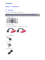
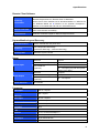
GV-DVR System V2 User’s Manual © 2008 GeoVision, Inc. All rights reserved. Under the copyright laws, this manual may not be copied, in whole or in part, without the written consent of GeoVision. Every effort has been made to ensure that the information in this manual is accurate. GeoVision is not responsible for printing or clerical errors. GeoVision, Inc. 9F, No. 246, Sec. 1, Neihu Rd., Neihu District, Taipei, Taiwan Tel: 886-2-8797-8377 http://www.geovision.com.tw The Windows XP Embedded is the componentized version of Microsoft Windows XP Professional, forsaking much functionality that Windows XP Professional provides and meeting the specific requirements of GV-Hot Swap DVR System V2. For details on embedded operation systems, please visit Microsoft's website. Trademarks used in this manual: GeoVision, the GeoVision logo, GV-Hot Swap DVR System V2, and GV series products are trademarks of GeoVision, Inc. Windows and Windows XP are registered trademarks of Microsoft Corporation. Other company and product names mentioned herein are trademarks of their respective companies. GeoVision assumes no responsibility with regard to the performance or use of these products. January 2008 User’s Manual for GV-DVR System V2 Welcome to the GV-DVR System V2 User’s Manual. The Manual provides an overview of the GV-DVR System V2 and its accessories. It also includes the instructions to guide you through the installation and use of the GV-DVR System V2: • Chapter 1, Introduction Identifies the GV-DVR V2’s accessories and options. • Chapter 2, Overview Identifies the GV-DVR V2’s components. • Chapter 3, Getting Started Provides step-by-step instructions on setting up the GV-DVR V2. • Chapter 4, DVR Health Analysis Introduces how to collect data to obtain the service of DVR health analysis from GeoVision. • Chapter 5, Troubleshooting Suggests courses of action if the GV-DVR V2 doesn’t seem to be working properly. The instructions and figures in this manual are based on GV-System version 8.2. Contents Regulatory Notices ................................................................................................... 4 Safety Instructions ................................................................................................... 5 Chapter 1 Introduction ......................................................................................... 6 1.1 Unpacking ................................................................................................................6 1.2 Models .....................................................................................................................8 1.3 Options ....................................................................................................................9 Chapter 2 Overview ............................................................................................ 10 2.1 Front View..............................................................................................................10 2.2 Rear View .............................................................................................................. 11 Chapter 3 Getting Started................................................................................... 12 3.1 Basic Installation....................................................................................................12 3.2 Turning on the Power.............................................................................................13 3.3 Configuring an IP Address .....................................................................................14 3.4 Extended Installation .............................................................................................16 3.5 Recovery DVD .......................................................................................................19 3.6 Updating GV-DVR System V2 ...............................................................................21 Chapter 4 DVR Health Analysis ......................................................................... 22 4.1 System Settings.....................................................................................................22 4.2 System Log............................................................................................................24 4.3 Information of Your Computer System ...................................................................25 4.4 Health Analysis Form.............................................................................................27 4.5 Check List ..............................................................................................................27 Chapter 5 Troubleshooting ................................................................................ 28 Specifications ......................................................................................................... 35 Warranty Policy....................................................................................................... 39 Warranty Form ........................................................................................................ 43 Regulatory Notices FCC Notice This equipment has been tested and found to comply with the limits for a Class A digital device, pursuant to part 15 of the FCC Rules. These limits are designed to provide reasonable protection against harmful interference when the equipment is operated in a commercial environment. Class A This equipment generates, uses, and can radiate radio frequency energy and, if not installed and used in accordance with the instruction manual, may cause harmful interference to radio communications. Operation of this equipment in a residential area is likely to cause harmful interference in which case the user will be required to correct the interference at their own expense. CE Notice This is a Class A product. In a domestic environment, this product may cause radio interference in which case the user may be required to take adequate measures. RoHS Compliance The Restriction of Hazardous Substances (RoHS) Directive is to forbid the use of hazardous materials of production. To meet the RoHS Directive requirements, this product is made to be RoHS compliant. WEEE Compliance This product is subject to the Waste Electrical and Electronic Equipment (WEEE) Directive and made compliant with the WEEE requirements. 4 Safety Instructions Observe these safety instructions to help ensure against injury to yourself and damage to the product. z Read all safety and installation instructions before you operate the product. z Do not operate the product in high humidity areas or expose it to water or moisture. z Do not put the product in an unstable, a slanting or vibrated place. z Do not block any ventilation opening. z Do not install the product near any heat sources such as radiator, heat register or other apparatus that produce heat. z Operate the product using only the type of power source indicated on the marking label. z Do not defeat the safety purpose of the grounding-type plug. A grounding plug has two blades and a third grounding prong. The third prong is provided for your safety. If the provided plug does not fit into your outlet, consult an electrician for replacement of the obsolete outlet. z Do not overload wall outlets or extension cords, as this may cause fire or electric shock. z Do not use the product when abnormality occurs, such as emitting smoke from the product, smelling burning, being damaged by drop, invasion of foreign objects inside the product, etc. Be always sure to remove the AC adaptor at once and contact your dealer. z Do not use accessories or attachments not recommended by the manufacturer, as they may cause hazards and void the warranty. z Do not attempt to service the product yourself, as removing the casing may expose you to dangerous voltage and void the warranty. 5 Chapter 1 Introduction 1.1 Unpacking The GV-DVR V2 package includes the following items: Important: Please keep the original carton and all packing materials for future shipping need. 1. GV-DVR System V2 x 1 2. D-Type Audio Cable x 2 (1 x 1-8 Channels Red Cable, 1 x 9-16 Channels Red Cable) 3. RJ-11 to DB9 Cable x 1 4. Lock Key x 2 5. AC Power Cord x 1 6 1 Introduction 6. GV-Keyboard Package x 1 7. IR Remote Control Package x 1 8. Self-Stick Rubber Pad x 4 9. Recovery DVD x 1 10. Nero Express CD x 1 11. Surveillance System Software CD x 1 12. GV-DVR System V2 User’s Manual x 1 13. GV-DVR System V2 Quick Start Guide x 1 14. Surveillance System New Feature Guide x 1 15. Surveillance System Installation Guide x 1 If any of the items are missing or damaged, contact your dealer to arrange a replacement. 7 1.2 Models The GV-DVR V2 has the following models: GV-2016S V2 - Sixteen-channel digital video recorder - Records up to 480 (NTSC) / 400 (PAL) fps at the D1 resolution - Has the option of 1600GB, 2000GB and 3000GB internal storage GV-2008S V2 - Eight-channel digital video recorder - Records up to 240 (NTSC) / 200 (PAL) fps at the D1 resolution - Has the option of 1200GB, 1600GB and 2000GB internal storage GV-1480S V2 - Sixteen-channel digital video recorder - Records up to 480 (NTSC) / 400 (PAL) fps at the CIF resolution - Has the option of 900GB, 1200GB and 1600GB internal storage GV-1240S V2 - Eight-channel or sixteen-channel digital video recorder - Records up to 240 (NTSC) / 200 (PAL) fps at the CIF resolution - Has the option of 600GB, 1200GB and 1600GB internal storage GV-1120S V2 - Sixteen-channel digital video recorder - Records up to 120 (NTSC) / 100 (PAL) fps at the CIF resolution - Has the option of 300GB, 600GB and 1200GB internal storage 8 1 1.3 Introduction Options Optional devices can expand your GV-DVR V2’s capabilities and versatility. Contact your dealer for more information. GV-Video Loop Through This card can take the video signal from the GV-DVR V2 and then Card split it into 16 signals while maintaining video quality. It can meet the need for multiple spot monitors. GV-IO 12-In Card With 12-point digital inputs, this card can expand the GV-DVR V2 up to 16 sensor inputs. GV-IO 12-Out Card With 12-point relay outputs, this card can expand the GV-DVR V2 up to 16 alarm outputs. GV-Multi Quad Card With this card, the GV-DVR V2 can connect up to 5 TV screens. The screen divisions on the TV screens can be definable. GV-Data Capture V3 Series GV-Data Capture V3 can integrate the GV-DVR V2 to an electronic POS system, while GV-Data Capture V3E can establish such integration through LAN or Internet. GV-I/O USB Box GV-I/O USB Box provides 16 inputs and 16 relay outputs, and up to 9 GV-I/O USB Boxes can chain together to expand the use. However, 16 inputs are only supported when it is used with GV-System version 8.2 or later. GV-Hub Box An easy way for serial port extension. This hub can add 4 RS-232/RS-485 serial ports through the GV-DVR V2’s USB port. GV-COM Box This unit can add 1 RS-232/RS-485 serial port through the GV-DVR V2’s USB port. GV-Joystick GV-Joystick facilitates the PTZ camera control. It can be either plugged into the GV-DVR V2 for independent use or connected to GV-Keyboard to empower the operation. However, this device can only work on GV-System version 8.2 or later. VGA Card With the VGA card, the dual display for monitoring and playback is made possible. RAM Multiple options for the amount of RAM are available to meet different needs. Hard Disk Multiple options for the HDD capacity are available to meet different needs. GV-DOM (Disk on Module) GV-DOM, a solid-state hard drive, is used for operating system and system software to get higher performance under harsh conditions. Note: The purchased GV-series cards will be added on the GV-DVR V2 before shipment. 9 Chapter 2 Overview 2.1 Front View 1 2 3 9 4 8 7 6 5 Figure 1 1 5.25” Hard Disk Compartment 6 Power Switch 2 Power LED 7 Reset Button 3 Hard Drive Activity LED 8 Key Lock 4 DVD ± RW Drive 9 USB Port x 2 5 Fan x 2 10 2 2.2 Overview Rear View Figure 2 1 RS-485 ± for PTZ Control 10 USB Port x 4 2 RJ-11 Port 11 VGA Monitor Port 3 D-Type Audio Port x 2 12 LPT Parallel Printer Port 4 BNC Connector x 16 13 DB-9 Serial Input 5 RCA TV Output 14 PS/2 Mouse Input 6 Audio Microphone In Port 15 PS/2 Keyboard Input 7 Audio Line In Port 16 AC Power Switch 8 Audio Line Out Port 17 AC Power Input (Full Range) 9 Ethernet Port x 2 11 Chapter 3 Getting Started 3.1 Basic Installation Basic installation describes all the equipments required to program and operate the GV-DVR V2. Figure 3 1. Using the supplied power cord, connect one end to the AC input and the other end to the power outlet. 2. Connect the keyboard to the PS/2 input. 3. Connect the mouse to the PS/2 input. 4. Using the VGA cable supplied by the monitor manufacturer, connect the VGA monitor. 5. For video lost beep, connect Speakers to the Audio Line Out port. 6. Using the RJ-45 cable, connect one end to the Ethernet port and the other end to Network. 7. Using the BNC video cables, connect one end to the BNC connectors and the other end to video sources. 8. Using the supplied D-type audio cables, connect one end to the audio ports and the other end to audio sources. Note: The monitor you use must be capable of having a screen resolution of 1280 x 1024 and display color of 32 bits. 12 3 3.2 Getting Started Turning on the Power Once the above hardware is properly connected, it is the time to turn on the GV-DVR V2. To turn on the power, follow these steps: 1. Turn on the monitor. On Figure 4 2. Turn on the AC power switch on the rear panel. Power On Figure 5 3. Turn on the main power switch on the front panel. Power On Figure 6 The GV-DVR V2 will run a series of self-tests. After two or three minutes, a series of messages may be displayed as the various hardware and software subsystems are activated. After this finishes, the GV-System Software (Multicam Surveillance System) should load automatically and bring you to the main screen with 8 or 16 cameras display. 13 3.3 Configuring an IP Address The purpose of configuring an IP address is to support the remote monitoring, control and configuration of the GV-DVR V2 over a network connection. The GV-DVR V2 is enabled for DHCP network. An IP address will be automatically allocated when the GV-DVR V2 is powered up. Despite the DHCP setting, it is recommended that a static IP address be configured on the unit. The GV-DVR V2 uses Windows operating system to configure an IP address. For this, you must exit to Windows. Note: Exiting to the Windows operating system is a protected feature. The default ID and Password is “0000”. Exit to Windows 1. Exit the main screen to display the GV-Desktop screen. Figure 7 Exit the main screen 2. Click the Settings button, and enter the valid ID and Password to display the Settings dialog box. 3. Under Desktop Type, select Windows from the drop-down list, and click OK. 4. Click the Log Off button, and enter the valid ID and Password to display the Windows desktop. 14 3 Getting Started 5. Configure a static IP address on the Windows XP platform. Check your network administrator if you have questions about the configuration. 2 4 3 Figure 8 The GV-Desktop Back to GV-Desktop Click the Windows Start button, point to Programs, select GVCombo, and click Key Lock Utility. Figure 9 Windows XP desktop 15 3.4 Extended Installation Beyond basic installation, the GV-DVR V2 package provides the following accessories to make your unit even more powerful and convenient: z GV-Keyboard z IR-Remote Control z RJ-11 to DB9 Cable for PTZ control GV-Keyboard The GV-Keyboard is designed to operate the GV-DVR V2 exclusively. Using the USB cable supplied with the GV-Keyboard, plug one end into the GV-Keyboard and the other end into the assigned USB port (COM3) on the front of the GV-DVR V2; you can operate the Keyboard immediately without installing any drivers. For details on the GV-Keyboard, find the Installation Manual included in its own package. Figure 10 It is also possible to plug the Keyboard into other USB ports of the GV-DVR V2. For this, you must modify the default COM port on the Multicam Controller pop-up once the Keyboard is connected. See Figure 11-1. 16 3 Getting Started To modify the default COM port: 1. Click to stop the Keyboard service first. 2. In the Port 1 field, modify the port number from the drop-down list. For the port allocation, refer to Figure 11-2. 3. Click to start the service. 1 USB & COM Ports Allocation on GV-DVR V2 Front Panel Rear Panel COM3 COM5 COM7 2 USB USB USB USB USB USB COM4 Figure 11-1 COM6 COM8 Figure 11-2 IR Remote Control The IR Remote Control is another plug-and-play device. Simply plug the Receiver into any USB ports of the GV-DVR V2. For details on the IR Remote Control, find the User’s Manual included in its own package. Figure 12 17 I/O Devices The GV-DVR V2, with built-in GV-NET/IO Card, provides 4 alarm outputs and 4 sensor inputs. Relay Output 1~4 Com Sensor Input 1~4 Ground Figure 13 PTZ Domes When connecting PTZ domes, you need to plug the supplied RJ-11 to DB9 cable into the DB9 port of the GV-DVR V2. RS-485+ PTZ Dome 1 RS-485- PTZ Dome 2 PTZ Dome 16 Connects to the DB9 port of the GV-DVR V2 RJ-11 to DB9 Cable Figure 14 18 DB9 Port 3 3.5 Getting Started Recovery DVD If preinstalled files are damaged, use the supplied Recovery DVD to restore them. To restore the operation system and all preinstalled software, follow these steps: Note: After recovery, you need to re-install all settings and passwords. But the recovery will not delete your recording files saved in the GV-DVR V2 since it only reformats the partition C and all of your files are still stored at other partitions. 1. Insert the Recovery DVD, and restart the GV-DVR V2. 2. The message “Are you sure want to recover C partition?” will appear. Click Yes. Figure 15 3. When the recovery is complete, the message “Operation completed. Please take out disks from DVD-ROM” will appear. Click Yes, and remove the DVD. Figure 16 19 Configuring the GV-DVR V2 for PAL after Recovery The default video standard of the Recovery DVD is set to NTSC. If the video standard in your country is PAL, remember to configure the GV-DVR V2 for PAL after using the Recovery DVD. 1. Click the Configure button, point to A/V Setting, and then select Video Source. Figure 17 2. In the Video Standard field, select PAL from the drop-down list, and click OK. Figure 18 20 3 3.6 Getting Started Updating GV-DVR System V2 GeoVision will periodically release the updated Recovery DVD including the latest GV-System Software (Multicam Surveillance System) and Windows updates. If you like to update your GV-DVR System V2, contact your dealer to get one. Before contacting your dealer, you may check software update news at our website: http://www.geovision.com.tw 21 Chapter 4 DVR Health Analysis GeoVision offers health analysis to the GV-DVR V2. The service is intended to give diagnosis for early and immediate detection of problems. It is recommended to have the health analysis during the first week after you install the GV-DVR V2, and then have the checkup every three months. It will take 5 working days for response. Please prepare the following data for analysis, and send to [email protected] z System Settings z System Log z Information of your computer system (Processor; Drives; Voltage, Temperature and Fans) 4.1 System Settings Please back up your system configurations using the Fast Backup and Restore application. 1. Run Fast Backup & Restore Main System from the Start menu. Figure 19 22 4 DVR Health Analysis 2. Select Backup System Settings. This dialog box appears. Figure 20 3. Press the Next Step button appears. to back up all your system settings. The Save As dialog box 4. Select the destination drive to store the backup file. When the backup is complete, this message will appear: Successfully Backup MultiCam System Settings. 23 4.2 System Log Please provide the sys*.mdb files of system log. The files by default are saved at D:\Log\database. If you have modified the default location, you can check the path by the following steps: 1. Click the Configure button on the main system, point to General Setting, and then select System Log Setting. This dialog box appears. Figure 21 2. Click Set Location. You should see the location of your system log. Figure 22 24 4 4.3 DVR Health Analysis Information of Your Computer System To get the information of your computer system, please follow the steps below to install the free software PC WIZARD. By using the software, the computer information can be easily collected and saved for analysis: z Processor: includes Type, Frequency, Data Cache L1, Trace Cache L1, Cache L2, Voltage, Processor Temperature, FPU Coprocessor. z Drives: includes Number of Hard Disk, Number of Drive, Total Size and Free Space of Drive. z Voltage, Temperature and Fans: includes Monitoring Chip, Voltage CPU, Chassis Fan, Processor Temperature, Mainboard Temperature, Hard Disk Temperature. 1. Download and install PC WIZARD from http://www.cpuid.com/pcwizard.php . 2. After installation, run the program. 3. Right-click the Processor icon , and click Save as. Figure 23 25 4. In the Save As dialog box, select Format HTML and click OK. Figure 24 5. Select the Save location, type the file name, and then click Save to save the Processor information as HTML file. 6. Repeat Steps 3-5 to save the Drives information as HTML file. 7. To save the Voltage, Temperature and Fans information A. , please follow these steps: Click the Voltage, Temperature and Fans icon. The related data is displayed at the right window. B. Click the first item Monitoring Chip. C. Click Edit on the menu bar and click Select All to highlight all the contents. D. Click Edit on the menu bar and select Copy. E. 26 Open a Notepad. Paste and save the information to TXT file. 4 4.4 DVR Health Analysis Health Analysis Form Please send the related data for analysis along with this Health Analysis Form to [email protected]. Health Analysis of GV-DVR V2 Contact Person: Title: Company Name: Telephone: (O) (H) Fax: E-Mail: Model: Bar Code: 4.5 Check List Read this check list before submitting the health analysis request: z System Settings- EXE file z System Log- sys*.mdb z Computer System- Processor information of HTML file z Computer System- Drives information of HTML file z Computer System- Voltage, Temperature and Fans information of TXT file z Health Analysis Form 27 Chapter 5 Troubleshooting GV-DVR System V2 is designed for durability. However, should problems occur, following the procedures here can help determine the cause. A portable 2.5'' HDD connected to the GV-DVR V2 front panel cannot be detected. When the portable 2.5” HDD connected to a GV-DVR V2 cannot be detected, try this step: Use a dual head USB cable and insert both heads to the USB ports on the GV-DVR V2 front panel as illustrated below. Figure 25 28 5 Troubleshooting The Main System cannot be minimized, and the GV-Desktop toolbar fails to appear. When the GV-DVR V2 is set up in a LAN where its router or server cannot assign the IP addresses through DHCP, the Main System may not be minimized, and the GV-Desktop toolbar may fail to appear. Try these steps: 1. Manually assign the fixed IP address to the GV-DVR V2. A. Unplug the Ethernet cable, and restart the GV-DVR V2. B. Go to the GV-Desktop, click the Programs button, and then select Disk Management. Figure 26 C. Right-click System (C:), and select Explore. Figure 27 29 D. Select Network Connections, right-click Local Area Connection, and then select Properties. Figure 28 E. In the Local Area Connection Properties dialog box, select Internet Protocol (TCP/IP) and then click Properties. Figure 29 30 5 F. Troubleshooting Select Use the following IP address, and type the IP info in the fields. Figure 30 2. Replace the router or server that can assign the IP addresses through DHCP in a LAN. GV-DVR V2 won’t turn on. If your GV-DVR V2 won’t turn on or you don't hear a startup sound or any fan or drive noise, try these steps: 1. Make sure that you switch on the AC power on the rear panel. Off On Figure 31 2. Make sure that the power cord is properly connected to both the GV-DVR V2 and power outlet. If you are using a power strip, make sure that the strip is powered on. 3. If the problem persists, consult your dealer. 31 GV-DVR V2 stops responding (aka “crashed” or froze”). If your GV-DVR V2 is not responding to your clicking, typing, or mouse movements, try these steps to get your GV-DVR V2 back on track. Please note that you will lose any unsaved changes in all open applications. 1. Restart your GV-DVR V2 by pressing the Reset button on the front panel. 2. If your GV-DVR V2 is still unresponsive, switch off the Power button to shut it down. Wait 30 seconds and then restart your GV-DVR V2. Reset Power On/Off Figure 32 GV-DVR V2’s hard disk corrupts. If you are experiencing file system corruption problems, such as lost clusters, cross-linked files or invalid files or directories, try these steps: 1. Use Windows built-in utility to scan your hard disk for errors and attempt to fix them. Follow these steps: A. On the GV-Desktop, click the Programs button, and select Disk Management. See Figure 26. B. Right-click the desired hard disk and select Properties from the file menu to display the Properties window. Figure 33 32 5 Troubleshooting C. Click the Tools tab in the upper portion of the window. D. Under Error-checking, click the Check Now button. Figure 34 E. Select Automatically fix file system errors and Scan for and attempt recovery of bad sectors. Figure 35 F. Click Start. 2. If the Windows hard disk utility still cannot fix the problem in Partition C, try rebuilding the operation system and GV-System Software by using the Recovery DVD. Refer to 3.5 Recovery DVD. 3. If the problem persists, replace a hard disk drive. GV-DVR V2 suffers virus attack. GV-DVR V2 is designed and optimized for Windows XP platform. It may be vulnerable to newly created worms and exploits that attack any of the underlying operating system’s previously undocumented flaws. If your GV-DVR V2 suffers virus attack, try rebuilding the operation system and GV-System Software by using the Recovery DVD. Refer to 3.5 Recovery DVD. 33 GV-DVR V2 has video and/or audio lost. If your GV-DVR V2 fails to show video, audio or both, try these steps: 1. Check the video/audio connection. Make sure one end of the D-type video/audio cable is securely connected to the video/audio device, and the other end to the video/audio port of the GV-DVR V2. 2. Make sure the video/audio device is turned on. 3. Switch the cable from the functional channel to the non-functional channel, and vice versa. If the previously non-functional channel is now able to deliver video/audio, you should check the video/audio device itself and its related cables. The screen image appears distorted or jitters. If the screen image seems to be distorted, jitter, or not to look right, try these steps: 1. Make sure the video standard in your country matches the setting in the GV-DVR V2. Refer to Configuring the GV-DVR V2 for PAL after Recovery in 3.5 Recovery DVD. 2. Make sure the camera and its cable are not damaged or frayed. Try to replace a camera or camera cable to see if this fixes the problem. How can I find more help? 1. Visit our website at http://www.geovision.com.tw/english/4_1.asp 2. Write us at [email protected] 34 Specifications Specifications System Model GV-2016S V2 CPU Intel Pentium Core 2 Duo Processor GV-2008S V2 GV-1480S V2 GV-1240S V2 GV-1120S V2 RAM 2 GB 1 GB 1 GB Dual Channel Dual Channel Dual Channel HDD 1600 GB 1200 GB 900 GB 600 GB 300 GB 2000 GB 1600 GB 1200 GB 1200 GB 600 GB 3000 GB 2000 GB 1600 GB 1600 GB 1200 GB OS Microsoft Windows XP Embedded VGA Intel GMA 3000 DirectX 9.0c DVD (±) RW 20X Fan Front: 3 fans Power 450 W, 110-230 V, 60-50 Hz Note: Multiple options for the HDD capacity, amount of RAM and type of VGA are available to meet different needs. Please contact your dealer or sales representative for further information. Video Model GV-2016S V2 Video Standard Input Level NTSC, PAL 16 8 16 channels channels channels 1.0 Vp-p (± 10%) composite, 75 Ω TV Output 1.0 Vp-p composite Video Loop Output (Optional) 16 channels Compression H/W: MPEG-2 / MPEG-4 (ASP) S/W: Geo MPEG4 / Geo Mpeg4 (ASP) / Geo H264 Geo H264 V2 Geo MPEG4 / Geo Mpeg4 (ASP) / Geo H264 / Geo H264 V2 NTSC 480 FPS 240 FPS 480 FPS PAL 400 FPS 200 FPS 400 FPS Video Input GV-2008S V2 8 channels GV-1480S V2 16 channels GV-1240S V2 GV-1120S V2 8 / 16 channels 16 channels 8 / 16 channels 16 channels * * Display Frame (Max) NTSC Display Resolution PAL 360 x 240 / 720 x 480 / 720 x 480 De-interlace 360 x 288 / 720 x 576 / 720 x 576 De-interlace Camera Name Max. 32 characters Screen Split Control 1x1 / 2x2 / 1+5 / 1+7 / 3x3 / 2+8 / 1+12 / 1+16 / 4x4 Screen Rotate Control 1 ~ 10 sec. Image Control Contrast / Brightness / Saturation / Hue Note: The functions with star marks * 320 x 240 / 360 x 240 / 640 x 480 / 640 x 480 De-interlace / 720 x 480 / 720 x 480 De-interlace 320 x 240 / 360 x 288 / 640 x 480 / 640 x 480 De-interlace / 720 x 576 / 720 x 576 De-interlace * * are only available on GV-System version 8.2. 35 Audio Model GV-2016S V2 GV-2008S V2 GV-1480S V2 GV-1240S V2 GV-1120S V2 Audio Input 16 channels 8 channels 16 channels 8 / 16 channels 16 channels Input Level 0.5 ~ 1 Vp-p composite Compression ADPCM / G.723 Recording Model Recording Frame Image Compression Dimensions GV-2016S V2 GV-2008S V2 GV-1480S V2 GV-1240S V2 GV-1120S V2 NTSC H/W: 480 (D1) H/W: 240 (D1) S/W: 480 (CIF) S/W: 240 (CIF) S/W: 120 (CIF) PAL H/W: 400 (D1) H/W: 200 (D1) NTSC 720 x 480 / 720 x 480 De-interlace PAL 720 x 576 / 720 x 576 De-interlace S/W: S/W: S/W: 400 (CIF) 200 (CIF) 100 (CIF) 320 x 240 / 360 x 240 / 640 x 480 / 640 x 480 De-interlace / 720 x 480 / 720 x 480 De-interlace 320 x 240 / 360 x 288 / 640 x 480 / 640 x 480 De-interlace / 720 x 576 / 720 x 576 De-interlace / * * Recording Mode Round the Clock / Motion Detection / Sensor Detection / Pre & Post Recording / Schedule Recording Schedule 96 groups per day by 15 min. Instant Playback 10 sec. / 30 sec. / 1 min. / 5 min. Pre Recording 1~ 90 sec. (1 FPS) Water Marking Support Note: The functions with star marks * are only available on GV-System version 8.2. Searching and Playback Search Method Date / Time Date / Time / Event Search Selectable on the tree list and calendar Log Search Through the log data to find the video event / time Backup Type 36 DVD+R (DL) / DVD-R (DL) / DVD+R / DVD+RW / DVD-R / DVD-RW / CD-R / CD-RW Specifications Remote Client Software Monitoring Environment WebCam Live View Remote Search WebCam / Twin Server / CenterV2 / VSM / Control Center / Remote Playback Server / Remote View / IP Multicast / GView V2 for PDA / MSView V2 for Windows Mobile 5.0 / MSView V3 for Windows Mobile 6.0 / SSView V2 for Symbian Smartphone / SSView V3 for Nokia S60 2nd and 3rd / 3G Mobile Phone Max. 16 channels transmission (Max. 200 channels accessible) * WebCam’s Remote Playback / Remote Playback Server Note: The functions with star marks * are only available on GV-System version 8.2. System Monitoring and Recovery Power Restoration Power restored after AC power loss Monitoring Two independent Watchdogs (Hardware Watchdog + Software Watchdog) Recovery DVD Automatic system rebuild Alarm Standard 4 inputs GV-IO 12-In Card (Optional) 16 inputs 8 ~ 72 inputs 16 ~ 144 inputs (only with GV-System version 8.2 or later) Sensor Input GV-IOUSB Box (Optional) Alarm Output Motion Detection Standard 4 outputs GV-IO 12-Out Card (Optional) GV-IOUSB Box (Optional) 16 outputs 16 ~ 144 outputs 16 channels Connector Video Input BNC 8 / 16 ports Video Loop Output (Optional) BNC 16 ports Audio Input RCA 8 / 16 ports Audio Microphone In Mini stereo jack Audio Output Mini stereo jack TV Output RCA RS±485 for PTZ Control 2-pin terminal Ethernet RJ-45, 10/100/1000 Mbps x 2 USB 2.0 Front: 2 ports, Rear: 4 ports VGA Output 15-pin female D Sub Remote Access TCP/IP 37 Environment Operating Temp. 0 ~ 50 °C (32 ~ 122 °F) Humidity 0 ~ 80% RH (non-condensing) Physical Model GV-2016S V2 IPC Case 4U Rackmount Color Silver Dimensions 483 (W) x 178 (H) x 528 (D) mm (19 x 7 x 21 inch) GV-2008S V2 GV-1480S V2 GV-1240S V2 300GB 17 Kg 600GB 17.6 Kg 17.6 Kg 18.8 Kg 18.2Kg 900GB Weight GV-1120S V2 1200GB 18.9 Kg 18.8 Kg 18.8 Kg 18.9 Kg 18.9 Kg 1600GB 19.2 Kg 19 Kg 2000GB 19.3 Kg 19.1 Kg 3000GB 19.5 Kg Language English / Czech / French / German / Hebrew / Hungarian / Italian / Type Japanese / Polish / Portuguese (Brazil) / Russian / Spanish / Simplified Chinese / Traditional Chinese Product design and specifications are subject to change without notice. 38 Warranty Policy Warranty Policy Warranty Coverage GeoVision, Inc. warrants GV-DVR System V2, IR Remote Control, and GV-Keyboard against defects in materials and workmanship for a period of TWO (2) years from the date of purchase. Other packaged accessories and software (including but not limited to System Software) are excluded. If a defect where due to causes attributable to GeoVision arises and a valid claim is received by GeoVision within the Limited Warranty Period, at its option, GeoVision will (1) repair the product at no charge, using new or refurbished replacement parts, or (2) exchange the product with a product that is new or which has been manufactured from new or serviceable used parts and is at least functionally equivalent to the original product. GeoVision warrants replacement parts or repairs for thirty (30) days from the date of GeoVision shipment or for the remainder of the Limited Warranty Period, whichever provides longer coverage for you. When a product or part is exchanged, any replacement item becomes your property and the replaced item becomes GeoVision’s property. Exclusions and Limitations The Customer shall have no coverage or benefits under this Limited Warranty if any of the following conditions are applicable: 1. The product has been subjected to abnormal use, failure to follow the instructions prescribed in User’s Manuals, improper storage, improper packaging, improper maintenance, unauthorized modifications, unauthorized repair, misuse, neglect, abuse, accident, alternation, improper hardware/software installations, or other acts due to causes not attributable to GeoVision, including damage caused by shipping. 2. The product was not purchased from an authorized distributor or agent. 3. The product has been damaged from exposure to rain, flood, storm, moisture, dampness, weather conditions, an Act of God, force majeure, improper use of any electrical source, or the connection to other products not recommended for interconnection by GeoVision. 4. Defects or damage caused due to virus attack. 5. The product bar code on the system case has been removed, defaced or altered. 6. The system case has been opened. 39 THIS WARRANTY IS IN LIEU OF ALL OTHER WARRANTIES, WHETHER ORAL OR WRITTEN, EXPRESS OR IMPLIED. THE WARRANTY IS LIMITED TO REPAIR OR EXCHANGE THE PRODUCT AT GEOVISION’S OPTION. OTHER EXPRESSED OR IMPLIED WARRANTIES FOR THIS PRODUCT, INCLUDING THE IMPLIED WARRANTIES OF MERCHANTABILITY AND FITNESS FOR A PARTICULAR PURPOSE ARE EXCLUDED IN DURATION TO THE WARRANTY PERIOD. NO WARRANTIES EXPRESSED OR IMPLIED WILL APPLY AFTER THIS PERIOD. GEOVISION SHALL NOT BE LIABLE FOR SPECIAL, DIRECT, INDIRECT, CONSEQUENTIAL DAMAGES. GEOVISION SHALL NOT BE LIABLE FOR LOST PROFITS, LOST OF DATA, PROGRAMS OR OTHER INFORMATION, DAMAGE TO OTHER PROPERTY CAUSED BY ANY DEFECTS OF THIS PRODUCT, OR DAMAGES BASED UPON INCONVENIENCE, LOSS OF PRODUCT USE, LOSS OF TIME, COMMERCIAL USE, INCIDENTAL AND/OR CONSEQUENTIAL DAMAGES FOR THE BREACH OF ANY EXPRESSED OR IMPLIED WARRANTY, INCLUDING DAMAGES TO PROPERTY, AND TO THE EXTENT PERMITTED BY LAW, DAMAGES FOR PERSONAL INJURY, OR OTHERWISE, EVEN IF GEOVISION HAS BEEN ADVISED OF THE POSSIBILITIES OF SUCH DAMAGES. Warranty Requirements To validate your purchase, you shall complete the online Product Registration within 30 days from the date of purchase at http://www.geovision.com.tw/english/4_6.asp. Or click GeoVision Online Registration in My Favorite for a direct link. If you fail to complete the Product Registration, the warranty period will start from the date of shipment. Before you return the product Some problems you experience may be related to software or the operating system. It is important to investigate other sources of assistance first. Before returning the product, try the following: 1. Review troubleshooting sections in the documentation for software and peripheral devices. 2. Try rebuilding the operation system and GV-System by using the Recovery DVD. 3. Consult your dealer. They are your best sources for current information and support. Or you can call or email GeoVision offshore offices for assistance. 40 Warranty Policy When you call or e-mail, please inform us the following: z Model name z Bar Code z Recovery DVD version z Details of the defect or problem z Attempted solutions z Your contact information z Reseller’s contact information 4. If you find it is the software problem, please check our website or your dealer for software updates. Obtaining Warranty Service If you are still unable to solve the problem and suspect that it is hardware related, follow these: 1. Send an e-mail to GeoVision to start Return Merchandise Authorization (RMA) process. E-Mail: [email protected] or [email protected] 2. Securely pack the product in its original carton using the original packing material, or in equivalent packaging. 3. The product shall be returned to GeoVision, Taiwan at your expense for shipping and insurance costs. BEFORE YOU DELIVER YOUR GV-DVR SYSTEM V2 FOR WARRANTY SERVICE, IT IS YOUR RESPONSIBILITY TO BACK UP YOUR DATA. YOU WILL BE RESPONSIBLE FOR REINSTALLING ALL DATA, SETTINGS AND PASSWORDS. DATA RECOVERY IS NOT INCLUDED IN THE WARRANTY SERVICE AND GEOVISION IS NOT RESPONSIBLE FOR DATA THAT MAY BE LOST OR DAMAGED DURING TRANSIT OR A REPAIR. 41 42 Warranty Form Warranty Form Thank you for purchasing the GV-DVR System V2. To help us validate your purchase and better serve you in the future, please go to http://www.geovision.com.tw/english/4_6.asp or click GeoVision Online Registration in My Favorite for a direct link to register online within 30 days from the date of purchase. Please keep this copy for your records. Name: First (given) Surname (family name) Company Name (only if the product is owned by company): Mailing Address: City/Town: Province/State: Country: Postal Code: Telephone: (O) (H) Fax: E-Mail: Date of Purchase: (e.g. 16-APR-2007) Product: Please check the item you purchased. GV – 2016S V2 – 16 Port – 1600 GB GV – 2008S V2 – 8 Port – 1200 GB GV – 2016S V2 – 16 Port – 2000 GB GV – 2008S V2 – 8 Port – 1600 GB GV – 2016S V2 – 16 Port – 3000 GB GV – 2008S V2 – 8 Port – 2000 GB GV – 1480S V2 – 16 Port – 900 GB GV – 1240S V2 – 16 Port – 600 GB GV – 1480S V2 – 16 Port – 1200 GB GV – 1240S V2 – 16 Port – 1200 GB GV – 1480S V2 – 16 Port – 1600 GB GV – 1240S V2 – 16 Port – 1600 GB GV – 1240S V2 – 8 Port – 600 GB GV – 1120S V2 – 16 Port – 300 GB GV – 1240S V2 – 8 Port – 1200 GB GV – 1120S V2 – 16 Port – 600 GB GV – 1240S V2 – 8 Port – 1600 GB GV – 1120S V2 – 16 Port – 1200 GB 43 Bar Code: Shipment Date: GeoVision, Inc. 9F, No. 246, Sec. 1, Neihu Rd., Neihu District, Taipei, Taiwan Tel: +886-2-8797-8377 Fax: +886-2-8797-8335 Email: [email protected] [email protected] http://www.geovision.com.tw 44