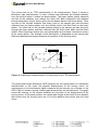
1
DX-4030 FTIR Gas Analyser On-site Series Instruction and Operating Manual 20.1.2009 DX-4030 USER MANUAL WARRANTY STATEMENT This warranty applies to the Gasmet brand name products sold with this warranty statement. This warranty is applicable in all countries and may be enforced in any country where Gasmet Technologies Oy or its authorised service providers offer warranty service subject to the terms and conditions set forth in this warranty statement. Gasmet Technologies Oy shall not be liable for technical or editorial errors or omissions contained herein. The information in this document is provided “as is” without guarantee of any kind and is subject to change without notice. Should you find any errors, we would appreciate if you notified us. Gasmet Technologies Oy guarantees that all products manufactured and sold by it are free of defects in materials and workmanship under normal use during the warranty period. Gasmet Technologies Oy’s products are manufactured using new materials or new and used materials equivalent to new in performance and reliability. Spare parts may be new or equivalent to new. Gasmet Technologies Oy agrees to either replace or repair free of charge (Ex Works Helsinki, Incoterms 2000) any such defective product or part that is returned to its repair facility within one (1) year of the delivery date. All parts or products removed under this warranty become the property of Gasmet Technologies Oy. The replacement product or part takes on the warranty status of the removed product or part. The warranty does not extend to any product from which the serial number has been removed or that has been damaged or rendered defective (a) as a result of accident, misuse, abuse, normal wear of components or other external causes; (b) by operation outside the usage parameters stated in the user documentation that is provided with the product; (c) by the use of parts not manufactured by Gasmet Technologies Oy; or (d) by modification or service by anyone other than Gasmet Technologies Oy. Gasmet Technologies Oy is not liable for any damages caused by the product or the failure of the product to perform, including any loss of profits or savings, incidental damages, or consequential damages. Gasmet™, Calcmet Lite™, and GICCOR™ are trademarks of Gasmet Technologies Oy. Windows® is a registered trademark of Microsoft Corporation. Teflon® is a registered trademark of E.I. du Pont de Nemours & Co., Inc. Viton® and Kalrez® are registered trademarks of DuPont Dow Elastomers. Bluetooth® is a registered trademark of Bluetooth SIG, Inc. 2 DX-4030 USER MANUAL CONTENTS WARRANTY STATEMENT ........................................................................................................2 CONTENTS...................................................................................................................................3 FIGURES .......................................................................................................................................5 TABLES.........................................................................................................................................6 PREFACE......................................................................................................................................7 1 INTRODUCTION .....................................................................................................................8 2 PRINCIPLE OF MEASUREMENT........................................................................................9 2.1 2.2 2.3 2.4 2.5 PRINCIPLES OF INFRARED SPECTROSCOPY ....................................................................... 9 COMPONENTS OF A FOURIER TRANSFORM INFRARED SPECTROMETER ......................... 11 QUANTITATIVE ANALYSIS OF FTIR SPECTRA .................................................................. 13 MULTI-COMPONENT ANALYSIS ......................................................................................... 15 THE SPECTRAL RESOLUTION OF FTIR ANALYSIS ........................................................... 16 3 GASMET DX-4030 FTIR GAS ANALYSER.......................................................................17 3.1 INTRODUCTION..................................................................................................................... 17 3.1.1 Applications of the Gasmet DX-4030 Analyser................................................... 17 3.1.2 Structure of the Gasmet DX-4030 Analyser........................................................ 18 3.2 GASMET DX-4030 TECHNICAL DATA ................................................................................ 19 3.2.1 General Parameters................................................................................................ 19 3.2.2 Spectrometer............................................................................................................ 19 3.2.3 Sample Cell .............................................................................................................. 19 3.2.4 Measuring Parameters ........................................................................................... 20 3.2.5 Electrical Connectors .............................................................................................. 20 3.2.6 Gas Inlet and Outlet Conditions ............................................................................ 20 3.2.7 Electronics ................................................................................................................ 20 3.2.7 Analysis Software (PDA) ........................................................................................ 20 3.2.8 Enclosure .................................................................................................................. 21 3.2.9 Analyser Enclosure ................................................................................................. 22 4 INSTALLATION ......................................................................................................................23 4.1 SUPPLY SCHEDULE ............................................................................................................. 23 4.1.1 Package .................................................................................................................... 23 4.1.2 Contents of the Gasmet Package ......................................................................... 23 4.1.3 Settings ..................................................................................................................... 24 4.2 AMBIENT CONDITIONS ......................................................................................................... 24 4.2.1 Storing and Transporting Gasmet......................................................................... 24 4.2.2 Installation Location................................................................................................. 24 4.2.3 Explosion Protection ............................................................................................... 24 4.3 GAS FITTINGS ...................................................................................................................... 25 4.4 ON-BOARD SAMPLE PUMP.................................................................................................. 25 4.5 POWER CONNECTION .......................................................................................................... 26 4.5.1 Battery ....................................................................................................................... 26 3 DX-4030 USER MANUAL 4.5.2 Power Supply ........................................................................................................... 26 4.5.3 Fuses ......................................................................................................................... 26 4.6 COMMUNICATION ................................................................................................................. 26 4.6.2 RS232 Interface ....................................................................................................... 27 5 START-UP ...............................................................................................................................28 5.1 SETTING UP THE DX-4030 ............................................................................................... 28 5.1.1 Pre-requirements ..................................................................................................... 28 5.1.2 Creating a Calcmet Application ............................................................................. 29 5.1.2 Creating a DX-4030 Application Using Calcmet 4030....................................... 30 5.1.3 Send a DX-4030 Application to the Analyzer Using Calcmet 4030................. 31 5.1.4 Checking the Application Sent to the Analyzer................................................... 32 5.2 SETTING UP THE PDA ....................................................................................................... 34 5.2.1 Installing the COMPONENTS.LIB File ................................................................. 34 5.2.2 Installing the CALCMETLITE.INI file .................................................................... 35 5.2.3 PDA Hints and Tips ................................................................................................. 36 5.3 STARTING UP AND OPERATING DX-4030 VIA BLUETOOTH ............................................ 36 5.3.1 Checking the Hardware Status.............................................................................. 37 5.3.2 Performing a Zero Calibration ............................................................................... 38 5.3.3 Starting the Measurements.................................................................................. 40 5.4 FLUSHING AND SWITCHING OFF THE DX-4030 VIA BLUETOOTH .................................... 43 5.5 STARTING UP AND OPERATING DX-4030 VIA RS232..................................................... 44 5.6 FLUSHING AND SWITCHING OFF THE DX-4030 VIA RS232 ............................................ 45 5.7 TRANSFERRING OF SPECTRUM/RESULTS FILE ................................................................. 45 5.8 SUMMARY .......................................................................................................................... 46 6 MAINTENANCE ......................................................................................................................47 6.1 SAFETY PRECAUTIONS ........................................................................................................ 47 6.2 MAINTENANCE PLAN ........................................................................................................... 47 6.3 VISUAL INSPECTION............................................................................................................. 48 6.4 SAMPLE CELL INSPECTION ................................................................................................. 48 6.5 REPLACEMENT OF OPTOELECTRONIC COMPONENTS ........................................................ 48 7 ANALYSER INSPECTION ....................................................................................................49 7.1 GASMET FTIR GAS ANALYSER INSPECTION SHEET.......................................................... 50 APPENDIX A: BLUETOOTH SETUP.....................................................................................51 APPENDIX B: INSTALL/UNINSTALL CALCMET LITE .....................................................52 APPENDIX C: VOCABULARY................................................................................................53 APPENDIX D: GASMET SALES AND SUPPORT OFFICES............................................54 4 DX-4030 USER MANUAL FIGURES Figure 1. The four normal modes of vibration of carbon dioxide CO2 molecule.............. 10 Figure 2. An absorbance spectrum of carbon dioxide CO2 measured with a DX-4015 model. c(CO2) = 50 ppm, T = 50 oC, absorption path length = 9.8 m. ........................ 11 Figure 3. The basic components of an FTIR spectrometer are infrared source, interferometer, sample cell, detector, and signal and data processing unit. .............. 11 Figure 4. A Michelson interferometer is a unique part of an FTIR spectrometer. ........... 12 Figure 5. A typical interferogram. ............................................................................................ 13 Figure 6. An example of spectra for multi-component analysis. The spectral analysis routine in Calcmet Lite software performs all calculations automatically.................... 15 Figure 7. Basic structure of the Gasmet DX-4030 analyser. .............................................. 18 Figure 8. Dimensional drawing of the DX-4030 analyser enclosure. ................................ 22 Figure 9. Sample gas fittings and connectors of the DX-4030 model............................... 25 Figure 10. Summary of COMPONENTS.LIB. ....................................................................... 34 Figure 11. Correct Calcmet Lite start-up sequence. ............................................................ 37 Figure 12. Calcmet Lite Hardware Status.............................................................................. 38 Figure 13. Calcmet Lite zero calibration. ............................................................................... 39 Figure 14. Activate pump during continuous measurement. .............................................. 39 Figure 15. Save spectrum files................................................................................................ 40 Figure 16. Save background files. .......................................................................................... 40 Figure 17. Save result file......................................................................................................... 41 Figure 18. Saving spectrum files and results. ....................................................................... 41 Figure 19. START - STOP measurement.............................................................................. 42 Figure 20. Measurement results (spectrum or analysis)..................................................... 42 Figure 21. Scrolling the results................................................................................................ 43 Figure 22. Switch OFF the analyzer. ...................................................................................... 44 5 DX-4030 USER MANUAL TABLES Table 1. Maintenance plan. ...................................................................................................... 48 6 DX-4030 USER MANUAL PREFACE Thank you for choosing Gasmet, the state-of-the-art FTIR gas analyser manufactured by Gasmet Technologies Oy. Gasmet is a high-technology product made of high quality components. The substantial investment of Gasmet Technologies Oy in R & D is targeted at innovative, customer-driven solutions. Working closely with customers and global distribution network, the company offers extensive technical applications support services. Along with high reliability, the products of Gasmet Technologies Oy offer easy operation and consistent and accurate results, together with competitive pricing. The development of the powerful technology of FTIR has required uncompromising commitment and expertise in several fields of high technology. As a result, the products of Gasmet Technologies Oy are not only superior in performance, but also simple to operate and maintain. The continuing philosophy of Gasmet Technologies Oy is to provide reliable measurements in a variety of industrial applications now and in the future. Wherever you are and whatever your applications are, we hope you will find the Gasmet gas analyser and its appliances fast, accurate, reliable, and easy to use. 7 DX-4030 USER MANUAL 1 INTRODUCTION This instructions manual provides information of the Gasmet DX-4030 Fourier transform infrared (FTIR) gas analyser. Please read this manual carefully and thoroughly prior to using the analyser. Improper use of the analyser may damage the equipment. Chapter 2 Principle of Measurement discusses theoretical aspects of infrared spectroscopy. These fundamentals help understanding the physical principles the Gasmet system is based on. Chapter 3 Gasmet DX-4030 FTIR Gas Analyser provides information about the Gasmet DX-4030 hardware and technical specifications. Chapter 4 Installation provides information of installing the Gasmet DX-4030 gas analyser. Use this paragraph to check the contents of the Gasmet package and to get Gasmet from storage into operational condition. Chapter 5 Start-up provides some basic information of the operation of the Gasmet DX4030. This chapter is recommended to read before any operation. Chapter 6 Maintenance describes the maintenance operations that are necessary periodically. Chapter 7 Analyser Inspection describes what should be done when the analyser is used the first time. This chapter includes inspection sheet, which should be filled within 30 days from the date of delivery to ensure that the warranty is valid in full. This instructions manual is copyrighted 2005 - 2008 by Gasmet Technologies Oy. All rights reserved. No part of this manual may be reproduced in whole or in part in any form without a prior written permission by Gasmet Technologies Oy. 8 DX-4030 USER MANUAL 2 PRINCIPLE OF MEASUREMENT 2.1 Principles of Infrared Spectroscopy Infrared (IR) spectroscopy is a technique for chemical analysis and determination of molecular structure in solid, liquid, and gas state. The principles that molecular vibrations occur in the infrared region of the electromagnetic spectrum and functional groups in chemical compounds have characteristic absorption frequencies are the basis of this technique. The frequencies of the most interest range from 2.5 to 16 µm. However, in IR spectroscopy it is common to use the reciprocal of the wavelength, called 'wave number', and thus this range becomes 4000 - 625 cm-1. An absorption spectrum demonstrates graphically to what extent the sample gas absorbs the different wavelengths of the infrared radiation. The spectrum shows the transmission of the infrared radiation through the gas as a function of wavelength. For each wavelength, the transmittance T is the intensity of the infrared radiation that has passed through the sample gas divided by the intensity of the infrared radiation that has entered the sample gas. When there is no absorption, the value of transmittance T is 1 (or 100 %), which indicates that 100 % of the infrared radiation at that wavelength goes through the sample gas. If the intensity of the radiation entering the sample is I0 and the intensity of the radiation that has passed through the sample is I, the transmittance T is: T = I / I o, T = transmittance I = passed intensity I = incident intensity Besides using transmittance T, the absorbance scale presents the absorption of the infrared radiation. Absorbance A is equal to the logarithm of the transmittance reciprocal: A = log10(I / T), A = absorbance T = transmittance The advantage of using the absorbance scale is that the value of absorbance is directly proportional to the thickness of the sample gas (absorption path length), and the concentration of the sample gas. 9 DX-4030 USER MANUAL Figure 1 shows how a carbon dioxide CO2 molecule behaves when it interacts with infrared radiation. All different vibrations, rotations, and their combinations result in absorption bands of specific wavelengths of the infrared radiation. O C O Symmetric stretch υ1 at 1388 cm-1 (This mode is not infrared active) Anti-symmetric stretch υ3 at 2349 cm-1 In-plane bend υ2 at 667 cm-1 Out-of-plane bend υ2 at 667 cm-1 Figure 1. The four normal modes of vibration of carbon dioxide CO2 molecule. The infrared absorption spectrum is unique to all different gas molecules. It is possible to identify any gas component from its IR spectrum. Figure 2 shows a carbon dioxide CO2 infrared absorbance spectrum. It can be seen that the anti-symmetric vibration band at 2349 cm-1 is the most intensive band while others are either outside of the range (900 - 4220 cm-1) or too weak in intensity. The band at ~3660 cm-1 is the combination band (i.e. sum) of υ1 and υ2. 10 DX-4030 USER MANUAL Figure 2. An absorbance spectrum of carbon dioxide CO2 measured with a DX-4015 model. c(CO2) = 50 ppm, T = 50 oC, absorption path length = 9.8 m. 2.2 Components of a Fourier Transform Infrared Spectrometer Figure 3 shows the basic parts that are typical for all non-dispersive FTIR spectrometers. A parallel, polychromatic radiation from an IR source is directed to an interferometer. The modulated beam is reflected through the gas sample cell. Finally, the detector detects the intensity of the infrared beam. The detected signal is digitized and Fourier transformed by the computer resulting in an IR spectrum of the sample gas. Infrared source Interferometer Sample cell Detector Signal and data processing unit Figure 3. The basic components of an FTIR spectrometer are infrared source, interferometer, sample cell, detector, and signal and data processing unit. 11 DX-4030 USER MANUAL The unique part of an FTIR spectrometer is the interferometer. Figure 4 shows a Michelson type interferometer. A mirror collects and collimates the infrared radiation from the source before it strikes the beam splitter. The beam splitter ideally transmits one-half of the radiation, and reflects the other half. Both transmitted and reflected beams strike plane mirrors, which reflect the two beams back to the beam splitter. Thus, one-half of the infrared radiation that finally goes to the sample gas has first been reflected from the beam splitter onto the moving mirror, and then back to the beam splitter. The other half of the infrared radiation going to the sample gas has first gone through the beam splitter and then reflected from the fixed mirror back onto the beam splitter. When these two beams from two optical paths are reunited, interference occurs at the beam splitter. The strength of the interference is depended on the optical path difference between the beams caused by the position of the moving mirror. Moving mirror Fixed mirror Source Beamsplitter Radiation to the sample gas and detector Figure 4. A Michelson interferometer is a unique part of an FTIR spectrometer. The optical path length difference (OPD) between the two optical paths of a Michelson interferometer is two times the physical displacement of the moving mirror. An interferogram is the interference signal measured by the detector as a function of the OPD. Figure 5 shows a typical interferogram produced by the interferometer. The graph shows the intensity of the infrared radiation as a function of the displacement of the moving mirror. At the peak position, the optical path length is the same for the radiation that comes from the moving mirror as it is for the radiation that comes from the fixed mirror. 12 Voltage U (mv) DX-4030 USER MANUAL -L 0 +L Optical path difference x/2 (cm-1) Figure 5. A typical interferogram. The spectrum is computed from the digitized interferogram by performing a Fourier transform by a computer utilizing a Fast Fourier Transform (FFT) algorithm. 2.3 Quantitative Analysis of FTIR Spectra The basic law for spectroscopic quantitative analysis is Beer's law (also known as the Beer-Lambert law). It shows how the concentration of the sample gas is related to the measured absorbance of the sample spectrum: log( I 0 / I ) = log(1 / T ) = A = abc Io = intensity of infrared radiation entering the sample I = intensity of the infrared radiation that has passed through the sample A = absorbance T = transmittance a = a (υ) = absorptivity (depends on wavelength) b = optical path length c = sample concentration The absorptivity a characterizes the capacity of the molecule to absorb infrared radiation. The value of a varies from a molecule to another and as a function of wavelength, but is constant for a given molecule at a given wavelength. The quantity b 13 DX-4030 USER MANUAL is the optical path length, that is, the distance the infrared radiation beam traverses in the gas sample. The quantity c indicates the concentration of the sample gas molecules in the sample. If the optical path length is constant, Beer's law states that the absorbance is directly proportional to the concentration of the sample gas at a given wavelength. Since Beer's law is additive, the total absorbance A is equal to the sum of the values of A of each gas component. Two conditions limit the use of the Beer's law in practice. The radiation is monochromatic, and the sample absorptivity does not vary with concentration. If the sample concentration range is wide, the change in the sample environment can cause absorptivity changes and deviations from Beer's law. For narrow concentration ranges and for low absorbance values a plot of concentration versus absorbance is nearly linear. The changes in the gas pressure caused by molecular collisions may bring about broadening in the absorption line shape of the sample gas. This affects all infrared bands. As the temperature increases, the population distribution of the molecules in different energy levels changes. The changes in the temperature cause changes in the absorption line shape of the sample gas. To measure the concentration of a gas compound, it is necessary to calculate the number of gas molecules in the sample cell. The number of the gas molecules in the sample cell depends linearly on both the gas pressure and the volume of the sample cell, and reciprocally on the gas temperature (ideal gas equation of state): pV = nRT, p = pressure V = volume n = number of gas molecules R = gas constant = 8.314 JK-1mol-1 T = temperature Any changes in sample gas temperature and/or pressure in the sample cell directly affect the measured gas compound concentration. In addition, gas pressure or temperature changes may affect the line shape of the measured absorbance spectrum, and thus the accuracy of the analysis results. 14 DX-4030 USER MANUAL 2.4 Multi-component Analysis The degree of absorption of infrared radiation at each wavelength relates quantitatively to the number of absorbing molecules in the sample gas. Since there is a linear relationship between the absorbance and the number of absorbing molecules, quantitative multi-component analysis of gas mixtures is feasible. To perform multi-component analysis we need a sample spectrum. In addition, we need reference spectra of all the gas components that may exist in the sample. A reference spectrum is a spectrum of one single gas component of specific concentration. In multicomponent analysis, we try to combine these reference spectra with appropriate multipliers in order to get a spectrum that is as close as possible to the sample spectrum. If we succeed in forming a spectrum similar to the sample spectrum, we get the concentration of each gas component in the sample gas using the multipliers of the individual reference spectra, if we know the concentrations of the reference gases. For example, suppose we have a sample spectrum and reference spectra like those shown in Figure 6. In this case, we know that the sample gas consists of gases Reference 1 and Reference 2. We have the reference spectra available and we know that these reference spectra represent concentrations of 10 ppm and 8 ppm, respectively. To find out the concentration of each component in the sample gas, we try to form the measured sample spectrum using a linear combination of the two reference spectra. We find out that if we multiply the spectrum Reference 1 by 5 and the spectrum Reference 2 by 2, and combine these two spectra we get a spectrum that is similar to the sample spectrum. Accordingly, the sample gas contains reference gas 1 at five times the amount in the reference spectrum 1, and reference gas 2 at two times the amount in the reference spectrum 2. The analysis indicates that the sample indeed consists of these two reference gases. The concentration of the reference gas 1 in the sample is found to be 50 ppm (= 5 x 10 ppm), and the concentration of the reference gas 2 in the sample is 16 ppm (= 2 x 8 ppm). Absorbance (in absorbance units) 0 .3 0 .2 5 0 .2 S am p l e 0 .1 5 R ef er en c e 1 R ef er en c e 2 0 .1 0 .0 5 0 Wave number (cm-1) Figure 6. An example of spectra for multi-component analysis. The spectral analysis routine in Calcmet Lite software performs all calculations automatically. 15 DX-4030 USER MANUAL 2.5 The Spectral Resolution of FTIR Analysis The spectral resolution of the measurement indicates how accurately it is possible to separate different wavelengths of radiation in the absorption spectrum. High resolution allows one to detect visually the exact location of narrow absorbance peaks and reduces spectral overlap. If it were possible to achieve infinite resolution, no deviations of Beer's law due to wide concentration range would occur. Thus, it would seem beneficial to have high resolution in order to get good results for the analysis. However, increasing the resolution causes other problems. For example, spectral noise increases and makes the analysis less precise. Furthermore, as high a resolution as possible does not maximize the information content of the measurement. Jaakkola et al. have shown 1 that low-resolution FTIR spectroscopy offers some valuable advantages compared to the traditional highresolution FTIR gas phase spectroscopy, especially in non-laboratory environments. This makes the use of low resolution quite worthwhile. To achieve precise quantitative analysis results, a low-resolution measurement should be used if the spectral analysis program can mathematically solve the spectral overlap. There are two reasons for the increase of the signal-to-noise ratio of an FTIR spectrum: • • In an FTIR spectrometer, the length of the measured interferogram determines the resolution. The longer the interferogram, the more data points is required, and the higher the resolution. In a high-resolution study, the time required by a single measurement is also long, so that we are able to accumulate less data in a fixed time, leading to higher noise level. Thus, the longer the measured interferogram is, the lower the signal-to-noise ratio. High resolution requires a small aperture to prevent a phenomenon called aperture broadening. Small aperture, in turn, reduces the signal and thus signal-to-noise ratio. 1 See, for example, P. Jaakkola, J. D. Tate, M. Paakkunainen, J. Kauppinen, and P. Saarinen, "Instrumental Resolution Considerations for Fourier Transform Infrared Gas-Phase Spectroscopy," Applied Spectroscopy 51 (1997) 1159 - 1169. 16 DX-4030 USER MANUAL 3 GASMET DX-4030 FTIR GAS ANALYSER 3.1 Introduction The Gasmet gas analysers are divided into four categories: On-line/CX- and FCXSeries, On-site/DX-Series, In-lab/CR-Series, and In-situ -Series depending on their properties and customers' application. All Gasmet analysers incorporate a Fourier transform infrared (FTIR) spectrometer, a temperature-controlled sample cell (except DX-4030), and signal processing electronics. The analyser offers versatility and high performance for all users. The Gasmet On-site/DX-Series includes the DX-4000, DX-4015, and DX-4030 models, which all are portable multi-component gas analysers for demanding industrial applications. The Gasmet DX-Series in designed for on-site measurements. It is an ideal tool to measure trace concentrations of pollutants in wet, corrosive gas streams. The sample cell maximum temperature is 180 °C (210 °C in a special configuration) in the DX-4000 and 50 °C in the DX-4015 model. Sample cell absorption path length is selected according to the application. The DX-4030 model analyser is designed for on-site measurements of various organic and inorganic compounds at low concentrations in ambient air. Typical usage areas include industrial hygiene and emergency response situations after incidents involving toxic chemical compounds. Analysis results of up to 25 pre-calibrated compounds are displayed on screen of an industrial-grade PDA. Optionally, the analyser can be connected to a laptop PC for extended analysis capability (e.g. identification of unknown compounds with library spectra). The key features of the Gasmet DX-4030 include a high sensitivity sample cell for lowest possible detection limits and a built-in-pump, which means that there is no need to use a separate sampling system. There are no consumable parts that would need replacing on regular basis. In addition, due to FTIR technology, the calibrations remain very stable. Hence, no span calibrations are needed. In addition, cross-references (i.e. interferences with other gases) are automatically compensated in the analysis algorithm during the calculation of the results. 3.1.1 Applications of the Gasmet DX-4030 Analyser The Gasmet DX-4030 analyser enables identification and quantification of multiple gaseous compounds simultaneously and accurately, with results available in seconds. The Gasmet DX-4030 is a versatile gas analyser that can be used in several applications. It is specially designed for: • • Industrial hygiene Emergency response 17 DX-4030 USER MANUAL 3.1.2 Structure of the Gasmet DX-4030 Analyser Figure 7 outlines the structure of a DX-4030 gas analyser. The infrared source produces broadband radiation, which interferometer modulates. The interferometer actually performs an optical inverse Fourier transform of the infrared radiation emitted by the infrared source. The modulated infrared radiation passes through the sample cell where sample gas absorbs certain wavelengths of the radiation. The detector detects the transmitted infrared radiation. The A/D converter digitizes the signal. The on-board digital signal processor (DSP) performs a mathematical Fourier transform on the digitized interferogram resulting in a spectrum. Fast Fourier Transform (FFT) is used to compute the spectrum from the interferogram. The FFT result is a transmittance spectrum. The absorbance spectrum is the ratio of the sample spectrum (transmittance spectrum) to the background spectrum. (The absorbance spectrum is computed from the transmittance spectrum). Gasmet uses the Calcmet Lite software to display the concentrations of the components present in the sample gas from the absorbance spectrum. Figure 7. Basic structure of the Gasmet DX-4030 analyser. The data and signal processing electronics control the operation of Gasmet. A PDA controls the Gasmet DX-4030 analyser. A unique part of Gasmet is the Gasmet Technologies Oy's GICCOR (an acronym for 'Genzel interferometer with a cube corner retroflector') interferometer. It is rugged and withstands the demanding environmental conditions of non-laboratory environment. The GICCOR interferometer modulates the infrared radiation coming from the infrared source, as discussed previously. The modulated infrared radiation passes through the sample cell. The gas sample is introduced into the gas cell through standard gas fittings. Thermoelectrically cooled detector then detects the transmitted infrared radiation. 18 DX-4030 USER MANUAL 3.2 Gasmet DX-4030 Technical Data 3.2.1 General Parameters Measurement principle: FTIR (Fourier Transform Infrared) spectroscopy Performance: Simultaneous analysis of up to 25 gas compounds (PDA), 50 compounds with optional Calcmet 4030 STD/PRO software (PC) Response time: < 120 s depending on the gas flow and measurement time Operating temperature: Ambient temperature -15 - +40 °C (not tested), non-condensing Storage temperature: −20 - +60 °C, non-condensing, dry place (batteries are recommended to be stored at temperature preferably not exceeding +30 °C). Power supply: 12 VDC battery and 100 W, 100 - 240 VAC, 50 - 60 Hz power supply 3.2.2 Spectrometer Interferometer: Gasmet Technologies Oy’s GICCOR interferometer Resolution: 8 cm-1 Scan frequency: 10 spectra/second Aperture: 1’’ Detector: Peltier cooled mercury cadmium telluride (MCT) detector Infrared source: Ceramic (SiC), at 1550 K temperature Beam splitter: ZnSe Optical window material: ZnSe Wave number range: 900 – 4200 cm-1 with ZnSe/MCTP 3.2.3 Sample Cell Structure: Multi-pass; fixed path length 9.8 m Material: 100 % gold and rhodium coated aluminium Mirrors: Fixed rhodium supported gold coating Volume: 0.45 dm3 Connectors: Festo 6 mm push-in fittings for SAMPLE IN, SAMPLE OUT, ZERO IN and interferometer PURGE Gaskets: Viton® o-rings (both Teflon® coated Viton® o-rings and Kalrez® coated Viton® o-rings are optional) Temperature: Ambient Maximum sample gas pressure: two bars Flow rate: 1 - 5 dm3/min Response time: < 30 seconds Required gas filtration: Filtration of particulates [two (2) microns)], (included in standard probe) Sample gas condition: Non-condensing 19 DX-4030 USER MANUAL 3.2.4 Measuring Parameters Zero point calibration: 24 hours calibration with nitrogen (5.0 or higher N2 recommended) Zero point drift: 2 % of smallest measuring range per zero-point calibration interval Sensitivity drift: None Linear derivation: 2 % of smallest measuring range Temperature drift: 2 % of smallest measuring range per 10 °C change, temperature measured and compensated Pressure influence: 1 % change of measuring value for 1 % sample pressure change, ambient pressure changes measured and compensated 3.2.5 Electrical Connectors Digital interface: Bluetooth protocol for communication in between the analyser and PDA (measurements and control of DX-4030). RS232, 9-pole D-connector to connect to PDA or to upload files and control analyser from external PC (optional, Calcmet 4030 STD/PRO software). Live measurement with PC and RS232 (optional, Calcmet 4030 PRO software). Power connection: Standard plug CEE-22 in (optional) power supply. 3.2.6 Gas Inlet and Outlet Conditions Gas temperature: Ambient temperature, non-condensing. Sample pump: Internal pump Flow rate: 120 l per hour Gas filtration: Filtration of particulates (2 μm) required, (included in standard probe) Sample gas pressure: Ambient 3.2.7 Electronics A/D converter: Dynamic range 95 dB Signal Processor: 2 * 32 bit floating point DSP 120 MFLOPS speed 3.2.7 Analysis Software (PDA) PDA: TDS Recon Operating system: Windows Mobile 6 Analysis software: Calcmet Lite Optional software (PC): Calcmet 4030 STD: application upload, analysis of spectra Calcmet 4030 PRO: application upload, analysis of spectra, live measurement Microsoft ActiveSync® in order to synchronise files in between PDA and computer PC using USB connector. 20 DX-4030 USER MANUAL 3.2.8 Enclosure Material: Aluminum Dimensions (mm): 383 * 348 * 145 Weight: 11.6 kg (with a battery) CE label: According to EMI guideline 89/336/EC CE mark indicates compliance with directive 89/336/EEC for electromagnetic compatibility. The CE marked Gasmet models are certified by the manufacturer as follows: Immunity: EN 61000-6-2 (1999) Emission: EN 50081-2 (1993) 21 DX-4030 USER MANUAL 3.2.9 Analyser Enclosure Figure 8. Dimensional drawing of the DX-4030 analyser enclosure. 22 DX-4030 USER MANUAL 4 INSTALLATION 4.1 Supply Schedule 4.1.1 Package Gasmet is shipped in a wooden box. To open the box, first open the lid of the box. Remove any additional smaller items on the top of the analyser. Finally lift Gasmet out of the box. Check that no items listed in chapter 4.1.2 Contents of the Gasmet Package remain inside the box. 4.1.2 Contents of the Gasmet Package The package contains: • • • • Gasmet FTIR gas analyser PDA + Charger, Windows Mobile 6.0 CD-ROM, including: 1. Application Tools folder (ADS application tools and Gasmet Tools application tools) 2. Gasmet Software folder a) Calcmet Lite setup b) Calcmet v10.xx setup 3. Quality Documents folder (ISO 9001 Certificate) 4. User Manuals folder a) Gasmet DX-4030 FTIR Gas Analyser Instruction and Operating Manual b) Calcmet User Manual 5. Calcmet LiteLibrary folder, which includes a) instrument-specific reference files b) reference spectra Excel sheet (description of the reference spectra) c) library and configuration files for analyser, components file for Calcmet Lite 6. Test folder (factory-measured SNR spectra, background spectra, and .ini file) Accessories: 1. RS232 cable 2. Battery + charger 3. Power source 100 – 240 VAC, 50 - 60 Hz 4. Standard probe 5. Backpack 23 DX-4030 USER MANUAL 4.1.3 Settings The following functions have been factory set in accordance with customer order specification: • software and analysis options in Calcmet Lite software 4.2 Ambient Conditions 4.2.1 Storing and Transporting Gasmet The instrument must be stored, installed, and operated in a dry and condensation-free place. The environment should be clean enough so that no dirt will accumulate on or inside of Gasmet. When Gasmet is in the package or not in use, store the equipment in following conditions: • • -20 - +60 °C storage temperature 5 - 95 % relative humidity, non-condensing Gasmet should not be exposed to strong mechanical vibration or shocks. Shocks during transport, for example, can cause serious damage. When transporting the instrument, use the original box with original shock absorbing materials. 4.2.2 Installation Location The installation location must be preferably free of strong vibrations. It is recommended that the instrument is operated in the following environmental conditions: • -10 - +40 °C operating temperature in short term use • 10 - 25 °C operating temperature in long term use • < 90 % relative humidity at 20 °C, non-condensing In some cases, heavy temperature changes may affect the analysis results and the accuracy of the measurements decreases. Re-measuring the background (zero) spectrum eliminates the influence of the temperature. Gasmet DX-4030 enclosure serves as heat radiator plate. Do not block the air circulation. 4.2.3 Explosion Protection For your own safety, Gasmet must not be used in hazardous areas. The standard enclosure is not explosion proof. Gasmet should not be used to measure explosive gas mixtures or gases that might form an explosive gas mixture with the ambient air. Gasmet Technologies Oy assumes no responsibility if Gasmet is used in hazardous areas. 24 DX-4030 USER MANUAL 4.3 Gas Fittings As seen in Figure 9, all sample gas fittings in the DX-4030 analyser are located on the side plate of the instrument. All the four gas connectors are Festo 6 mm push-in fittings. A tube with outer diameter of 6 mm can be directly pushed into the fittings. The sample gas connectors are: • • SAMPLE IN and OUT are Festo 6 mm push-in fittings The DX-4030 model has a SPAN IN (Festo 6 mm push-in) inlet in addition to the SAMPLE IN and OUT fittings. It can be used to flush the sample gas cell prior a background spectrum measurement. The analyser's PURGE gas fitting is located on the front of the enclosure. PURGE connector is a Festo fitting, as well. Only N2 or dry and clean instrument air should be used to purge the analyser. Figure 9. Sample gas fittings and connectors of the DX-4030 model. 4.4 On-board Sample Pump The sample gas of DX-4030 is in ambient temperature. As the temperature is rather low, sampling system can be relatively simple. The DX-4030 model is equipped with an on-board sample pump package, which has a neoprene diaphragm pump. Power supply is 12 VDC, maximum pressure 1.0 bar, and maximum flow is 2.8 l/min. 25 DX-4030 USER MANUAL 4.5 Power Connection DX-4030 can be used with battery (included) or AC power supply (included). 4.5.1 Battery The DX-4030 analyser has a 12-volt lithium ion battery. The operating time in continuous measurement is approximately in between two and a half (2.5) to three (3) hours. The operating temperature is same as with the analyser and the recommended storage temperature should preferably not exceed +30 oC. Batteries are recommended to be charged at ambient temperature. For long-term storage, keep the battery within a 30 % state of charge. 4.5.2 Power Supply The required mains input is 100 VAC up to 240 VAC, 50 Hz- 60 Hz. Hold-up time of Gasmet is 20 ms from loss of AC input. Use an uninterruptible power supply (UPS) if the electric power is subject to major disturbances or power failures. Connect the power cable to Gasmet power supply unit that is equipped with standard CEE-22 plug. Never connect Gasmet to a mains (AC electrical power) supply that has no protective ground. Preferably, be sure that manual power switch is OFF before connecting the power cable to Gasmet. 4.5.3 Fuses If you have to replace fuses, you may only use those that correspond exactly to specified values (4A T, physical size 5 x 20 mm). Before checking the fuses, switch the power off. Fuses are located behind the IEC (International Electrotechnical Commission) power inlet unit. 4.6 Communication DX-4030 is operated with Calcmet Lite software on PDA. Communication between PDA and analyser uses either Bluetooth or RS232. Optionally, DX-4030 can be operated with Calcmet 4030 PRO via RS232. 4.6.1 Bluetooth Communication Bluetooth communication is used to measure and/or record spectra in live. It is used as well to display and record analysis results. Startup of the analyzer can also be made by Bluetooth using PDA. 26 DX-4030 USER MANUAL 4.6.2 RS232 Interface RS232 interface can also be used for communication between the DX-4030 and the PDA. RS232 interface also allows connection to external PC to upload application files (optional, Calcmet 4030 STD/PRO) or live measurement (optional, Calcmet 4030 PRO). 27 DX-4030 USER MANUAL 5 START-UP Before starting to operate the Gasmet FTIR gas analyser, read this Instruction & Operating Manual carefully and thoroughly. If you do not understand something or you are unsure what to do, please do not hesitate to contact your local distributor or Gasmet Technologies Oy. The contact information is at the bottom of every page. It is intended that the user knows how to use a PDA running under Windows mobile. For further information, please refer to the PDA manual and Windows Mobile website. Please remember that measuring conditions should be non-condensing. 5.1 Setting Up the DX-4030 Setting up DX-4030 is normally not required at start up, as the analyzer has been setup in Gasmet Technologies Oy. However, when a new application needs to be uploaded into the DX-4030, those following steps are required. 5.1.1 Pre-requirements Before creating an application using Calcmet 4030 software and sending that to the DX4030, ensure that: – – – – – – – – – – Microsoft ActiveSync is installed on the computer if you use Windows XP OS (from http://www.microsoft.com/windowsmobile/activesync/ or CD provided with the PDA package). If you use Windows Vista, Microsoft ActiveSync is not needed. 115V~/230V~ power supply is plugged onto the analyzer. HASP key is connected to your computer. Analyzer is connected to the DX-4030 via Gasmet serial cable. PDA is synchronized (connected) to your computer via USB cable. Calcmet Lite is installed on the PDA. Calcmet 4030 Standard or Professional (data format = 16 bits; baud rate = 57600; correct COM port) is running on your computer. Manual power switch is set to “1”. Power On LED light is green. 28 DX-4030 USER MANUAL 5.1.2 Creating a Calcmet Application The first step is to create an application in Calcmet (please read the Calcmet manual in order to get further information on how to create an application). When you create an application in Calcmet 4030, some limitations have to be considered: – – – – Water H2O should all the time be declared as first component, and component name has to include “H2O” The number of components, which can be analyzed, is limited to 25 components. The number of reference spectra to be used in the library is limited to 50 reference spectra. The total analysis area of the entire application is about 3500 cm-1 (464 spectrum points). Difference in between the highest wave number analysis area and the smallest wave number analysis area – The largest single analysis area for one application is about 690 cm-1 (90 spectrum points). The largest single analysis area is the difference in between the highest wave number and the smallest wave number for analyzing one component. In this example: Largest single analysis area = 3150 cm-1 – 2600 cm-1 = 550 cm-1 29 DX-4030 USER MANUAL – When using different analysis areas, be careful that the areas do not overlap for the analysis of one component! For the analysis of hexane, the analysis areas overlap. This combination is forbidden when creating applications for the DX4030. – – – – Slope, Curve, and Double Reference Fitting correction are possible for the different components. Path Length, Ambient Pressure or Cell Pressure (NOT External Pressure) and Sample Cell Temperature compensation are possible. The combination of components (like NOx) is possible only if you want to sum different concentrations (for example: concentration in NOx = concentration in NO + concentration in NO2). Display of the analyzer parameters is possible. Below is the list of the analyzer components that can be displayed: • • • • • • • 219: Ambient Pressure 222: Sample Cell Pressure 231: Sample Cell Temperature 232: Interferometer Temperature 233: Detector Temperature 234: IFG Peak Height 235: Interferogram Center 5.1.2 Creating a DX-4030 Application Using Calcmet 4030 When the application is created in Calcmet 4030, the next step is to generate the DX4030 application to the analyzer. – Go to DSP → Generate Application Files… – The following dialog box should appear. Enter the name and the directory where you want to store your DX-4030 application files. One config file and one library file is going to be generated. – 30 DX-4030 USER MANUAL – When those 2 files have been generated, 2 dialog boxes should appear: – – – Be sure that the created application is below or equal to the maximum limits. If it is the case, DX-4030 application is ready to be sent to the analyzer. Otherwise, modify Calcmet application and repeat the process. – Two text files are created when using the command “Generate application files”: o One “config” file (size about 5 KB) which include: o Number of components to be analyzed. Compensations used in the application. Lower and higher background signal limits. Analysis method. List of the addresses in the DSP memory where the spectra are stored. One “library” file (size about 120 KB for about 20 components) which include: Components options. Analysis areas for the different components. Cross interferences. Reference files. 5.1.3 Send a DX-4030 Application to the Analyzer Using Calcmet 4030 When the DX-4030 application is created, the next step is to send it to the analyzer. – Go to DSP → Send file… – – The following dialog box (on the right) should appear. Select one of the generated file and click “Open”. Send first the “config” file as it is the smallest one. – During uploading of the file, the following progress bar appears. – Correct upload finish with the following dialog box: 31 DX-4030 USER MANUAL – – – – – – If the config file has been sent properly, send the “library” file using the same process. Otherwise, ensure that the analyzer is powered and that the Gasmet serial cable is properly attached. Repeat then the sending routine. A 120 KB file should take less than 10 minutes to be sent to the analyzer. Do not forget to send the “config” file and then the “library” file because the analysis would not work at all otherwise! If you change the application on Calcmet (whatever the change is), you should all the time regenerate the application and send the two text files to the analyzer. When you send a new application to the DX-4030, this new application will overwrite the previous one. When the two files have been sent to the DX-4030, restart the system by using the manual power switch in order to load the new application. 5.1.4 Checking the Application Sent to the Analyzer At this point, you created and sent successfully one DSP application to the analyzer. Calcmet 4030 Standard and Professional provides extra set of commands in order to test the DX-4030 application. It is then possible to take a background from Calcmet that will be save in the analyzer, send spectrum files to the analyzer in order to be analyzed and get “live” analysis results from the analyzer. – In order to measure and save a background in the analyzer, go to DSP → Measure Background. o If you use Calcmet 4030 Standard, you will be able to measure a background and save it to the DX-4030 but you will not be able to check the measured background on Calcmet. If you use Calcmet 4030 Professional, you will be able to measure a background and save it to the DX-4030 AND you will be able to check the measured background on Calcmet. o 32 DX-4030 USER MANUAL – Spectrum files can be uploaded to the system in order to be analyzed by the DX-4030. A dialog box will appear allowing you to locate and select the spectrum file to be analyzed. Go to: DSP → Analyze. – DX-4030 can measure and display in “live” analysis results on Calcmet. Go to: DSP → Analysis results. Remember to use the same application than the one uploaded into the analyzer when Analyze and Analysis results command are used. That way, no mismatch will be created in between the analyzer application and Calcmet application. When the above checks are validated, your DX-4030 is ready to operate. The PDA needs then to be setup. 33 DX-4030 USER MANUAL 5.2 Setting up the PDA Setting up the PDA (Personal Digital Assistant) is normally not required at the start-up, as it has been set up in Gasmet Technologies Oy. However, when a new application is installed in the DX-4030, some modifications are required as well in the PDA. Calcmet Lite software is installed in the PDA. Calcmet Lite starts up the DX-4030 via Bluetooth (if the Bluetooth connection is used), measures background, and stores it in the analyzer, measures spectrum files, and display analysis results. Contrary to Calcmet software, Calcmet Lite does not allow to analyze spectrum files. The analyzer is responsible for the analysis! Calcmet Lite just triggers a measurement and receives a “row” of concentration results from the analyzer. Calcmet Lite does not know by default the application loaded in the analyzer. That is the reason why, one file stored in Calcmet Lite specifies the application loaded in the analyzer. This file is COMPONENTS.LIB. Calcmet Lite requires an initialisation file in order to keep in memory the user settings. This file is CALCMETLITE.INI. 5.2.1 Installing the COMPONENTS.LIB File COMPONENTS.LIB file is equivalent to the *.LIB file which is created by Calcmet during application setup. The *.LIB file needs to be copied and renamed to COMPONENTS.LIB (Figure 10). Then, copy COMPONENTS.LIB file into the PDA, using ActiveSync USB, under the directory \Program Files\CalcmetLite\. Calcmet Lite uses COMPONENTS.LIB in order to display properly on the screen component names, component ranges, component residual limits, component alarms. Create “Application.LIB” Example Copy and Rename GASLIB-DEMO-DSPBoard.LIB to COMPONENTS.LIB USB Figure 10. Summary of COMPONENTS.LIB. Copy under \Program Files\CalcmetLite\ 34 DX-4030 USER MANUAL Please, refer to Microsoft ActiveSync® documents if you need further information about how to access PDA memory via ActiveSync. 5.2.2 Installing the CALCMETLITE.INI file CALCMETLITE.INI is located in the PDA under the directory \Program Files\CalcmetLite\. This file includes the definition of the Device ID of the DX-4030, its Bluetooth address, the COM Port that Calcmet Lite will use, the Baud Speed, the location of the different recorded files to be stored on the PDA, the minimal and maximal signal limits for the background, the timer defining the analysis time onto the DSP. In order to modify CALCMETLITE.INI, copy the file from the PDA (\Program Files\CalcmetLite\ directory) to the desktop using ActiveSync. Open the file using a simple text editor like Notepad. – Device ID: Each Gasmet DX-4030 analyzer contains a device ID. This ID depends of the serial number of the analyzer. Gasmet sets the ID such way: GASMET+”Serial number of the analyzer”. • • • Example: GASMET071170 Device ID will be displayed when you search for a Bluetooth module with the PDA. Calcmet Lite displays device ID during start up if the correct DX-4030 is found. – Bluetooth address: Each Gasmet DX-4030 analyzer contains its own device ID and its own Bluetooth address. The Bluetooth address is used by the Bluetooth search software to discover a Bluetooth device (Please, refer to the manual: TDS Recon Bluetooth Settings” in order to set up a Bluetooth connection with the analyzer). When Calcmet Lite starts, the Bluetooth address of the analyzer is checked and compared to the Analyzer Bluetooth address stored in the CALCMETLITE.INI file. If the result of the comparison is positive then, the Device ID AND the Bluetooth address are displayed in Calcmet Lite. – COM Port: This number corresponds to the Bluetooth COM Port defined (By default, it is COM8). This value can also be 1 if the traditional RS232 COM Port is used with the Gasmet Serial Cable. – Baud Speed: Serial communication baud speed of the analyzer: 57600 bps by default. – – Path of the different recorded files: Backgrounds, spectrums and results. Minimal and maximal signal limits for background: By default, MinSignalLimit = 5000 and MaxSignalLimit = 30000. After a background is measured, Calcmet Lite checks it using MinSignalLimit and MaxSignalLimit. The information below explains how this check is made: 35 DX-4030 USER MANUAL All spectrum points are checked and the maximum value has to be above or equal to MaxSignalLimit. Spectrum points in between 900 cm-1 and 4250 cm-1 are checked and minimum value has to be above or equal to MinSignalLimit. • If the background taken by Calcmet Lite (and saved in the DX-4030) fulfills the previous criteria’s, then Calcmet Lite saves the background in memory. • If not, the background is saved and a window will be displayed after background measurement in order to notify the user that the background is low. – Timer: The Timer parameter defines the time (in ms) taken by the DX-4030 to analyze a spectrum. Depending of the application size, the analysis can take hundreds of milliseconds to a couple of seconds before sending the results to Calcmet Lite. This parameter needs to be fine-tuned depending on the application loaded to the DX-4030. If the Timer is set too low and the analysis takes more time than what is defined by the timer parameter, the results will not be displayed on the PDA. Instead, if the Timer is set too high, you might have some communication issues especially when the PDA is far (more than 5 meters) of the DX-4030. On the contrary, if the timer parameter is set too high, you might have some communication issues especially when the PDA is far (more than 5 meters) from the DX-4030. 5.2.3 PDA Hints and Tips • • • • When a new application is loaded in the DX-4030, COMPONENTS.LIB file needs to be updated in the PDA side in order to match the application in between the analyzer and Calcmet Lite. When a new application is loaded in the DX-4030 and COMPONENTS.LIB is updated in the PDA, use Calcmet Lite and start the analysis in order to check if the timer parameter in CALCMETLITE.INI needs to be modified. Before reinstalling Calcmet Lite application, backup the following files: COMPONENTS.LIB, CALCMETLITE.INI, and CALCMET.BKG. After Calcmet Lite upgrade, you will just need to copy back those backup files under \Program Files\CalcmetLite\ directory in order to run your instrument. When removing Calcmet Lite program on the PDA, go to: Settings → System tab → Remove Programs → Select Calcmet Lite and click Remove. When Calcmet Lite is uninstalled, all the files under the CalcmetLite directory are deleted except the log file. Be sure that COMPONENTS.LIB, CALCMETLITE.INI and CALCMET.BKG files are backed up before starting to uninstall Calcmet Lite. 5.3 Starting Up and Operating DX-4030 via Bluetooth Before starting to use the DX-4030 in standalone mode, ensure that the PDA and analyzer batteries are fully loaded. DX-4030 batteries are fully loaded when the charger displays a green led. 36 DX-4030 USER MANUAL PDA battery power can be check by going to: Settings → System tab → Power. – – Connect the battery (field-use) or the power supply (laboratory-use). Check the condition of sample probe filter (change the filter, if necessary). The following settings in the PDA should be activated: COM Port settings in CALCMETLITE.INI should be 8 (factory settings). – PDA should be paired with the DX-4030 (factory settings). – The following settings in the DX-4030 should be verified: – – – – – – – Manual Power switch should be set to “0”. Bluetooth Led should be blue. Use the furnished stylus pen attached in the back of the PDA and click on the Calcmet Lite icon or go to: Start –> Calcmet Lite (Figure 11). If the Bluetooth connection is established, DX-4030 is powered up. Bluetooth Led should be blue and Power Led should be green. A yellow square appears in the bottom left corner of Calcmet Lite. This information indicates that the system booted properly and that the Bluetooth communication from the DX-4030 to the PDA is validated An info notification appears on the screen with the ID and the Bluetooth address of the analyzer. A green square appears after a couple of seconds. Calcmet Lite and the DX-4030 are ready to measure. Figure 11. Correct Calcmet Lite start-up sequence. – If a red square appears in the bottom left corner of Calcmet Lite (Calcmet Lite Demo Mode), it means that the Bluetooth connection is not established with the analyzer or that the power sequence on the analyzer failed. Please, ensure that the power supply is correct both on the PDA and on the analyzer side and restart the start up procedure. In addition, you may need to shorten the physical distance in between the PDA and the analyzer. 5.3.1 Checking the Hardware Status The first step to accomplish after powering up the DX-4030 is to measure some hardware parameters in order to validate the functioning of the analyzer. A simple check 37 DX-4030 USER MANUAL in Calcmet Lite to the hardware status informs the user that the instrument is ready to operate. In order to access to hardware status, click to: Measure → Hardware Status. After 1 second, hardware parameters should appear (Figure 12). Figure 12. Calcmet Lite Hardware Status. Hardware parameters to check are the followings: – – – – – – – – – Cell Temp: Temperature of the sample cell, which should be higher/close to the ambient temperature. Ambient Pressure: Pressure of the atmosphere in millibars. Cell Pressure: Pressure of the atmosphere in millibars. Source Intensity: The percentage of source intensity indicates the state of the IR source inside the interferometer. This percentage is close to 100 % when the DX-4030 leaves the factory. Interf. Height: The interferogram height is the maximum value (in volts) of a measured interferogram. This value depends of the sample that is inside the sample cell. When the sample cell is flushed with nitrogen, interferogram height should be close to +5.4 V. During sample measurement, this value can decrease by a factor of 2. Interf. Center: The interferogram center informs about the quality of the interferogram measured. This value can oscillate in between 2000 to 3000 points without analysis error. Center point value decreases when the enclosure temperature increases. Electronics Temp.: Electronics temperature is measured on the main electronics board. This value can be 0 - 50 oC. Detector Temp.: Detector temperature is the temperature measured on the Peltier element of the IR detector. This value is normally close to -37 oC. Ext. Detector Temp.: External detector temperature is the temperature measured in the detector enclosure. This value is normally close to +25 oC. If the hardware status parameters are correct, the instrument is ready to perform a zero calibration. 5.3.2 Performing a Zero Calibration DX-4030 requires a zero calibration before starting to operate (Figure 13). Calibration requires the use of nitrogen or dry air. For better stability of the instrument, wait for the analyzer to warm up during 10 minutes before zero calibration. – – Be sure that the internal pump is not activated. That way, you will be able to test that the background is taken properly. Go to Settings → Measure Options tab. Uncheck: Activate Pump during continuous measurement. Set up the measuring background time. This time is correlated to the sample measurement time defined in Measuring Time. A recommended measuring time is 5 or 20 seconds. These 38 DX-4030 USER MANUAL – – – – measuring times correspond to 20 second and 60-second background times. Click ok on the top right end corner. The longer the measurement time is, the better the accuracy of the analysis results. Measuring time depends then of your application. Be sure that the analysis is switched ON. Go to Measure and check Analyze. Flush the sample cell using a 6 mm Teflon tube attached to the Span/N2 In fitting. Zero gas should be nitrogen gas (quality 5.0 or higher) or clean/purified instrument air. In case neither is available, ambient air can be used. However, analysis performance will be impaired. Recommended flow should be about 3L/min. Wait for one minute to be sure that the sample cell is correctly purged. Trigger a zero calibration by clicking to: Measure → Zero Calibration. Figure 13. Calcmet Lite zero calibration. – – An incorrect zero calibration is notified with a message printed in the screen: "Background Signal Low!" (Please, read section “install CALCMETLITE.INI file” in order to get further information concerning background check). Trigger a continuous measurement by clicking to: Measure → Continuous (check that the analysis mode is enabled). The point is to check that, after zero calibration, the analysis results are around 0 (if the sample cell is still purged with zero calibration gas). Pump needs to be deactivated when you check the zero calibration otherwise sample gas will enter the sample cell and zero results are invalid. – After a successful zero calibration, sample measurements can be performed. The sample pump is switched on when continuous measurement is started if pump mode is activated in File → Settings → Measure Options → Activated Pump during continuous measurement (Figure 14). Figure 14. Activate pump during continuous measurement. 39 DX-4030 USER MANUAL 5.3.3 Starting the Measurements At this point, please consider whether the measurements are stored in PDA memory or not. There are four alternatives: – Store the sample spectra (Figure 15). Sample spectra can then be downloaded onto the desktop and analyzed using Calcmet software. Go to File → Settings → Autosaving tab → Autosave Sample Spectra: All. Click “Browse...” to specify the folder and the name given to the saved spectrum files. Use the “built in” keyboard to enter the spectrum name. Be sure that the analysis is switched OFF. Go to Measure and uncheck Analyze. Figure 15. Save spectrum files. – Store the background files (Figure 16). Background spectra can then be downloaded onto the desktop and checked using Calcmet software. Go to File → Settings → Autosaving tab → Check Autosave Backgrounds. Click “Browse...” to specify the folder and the name given to the saved background files. Use the “built in” keyboard to enter the background name. Figure 16. Save background files. – Store the measurement results as a text file (*.txt) (Figure 17). Go to File → Settings → Result Output tab → Check Autosave Results. Click “Browse...” to specify the folder and the name given to the saved result files. Use the “built in” keyboard to enter the spectrum name. Be sure that the analysis is switched ON. Go to Measure and check Analyze. 40 DX-4030 USER MANUAL Figure 17. Save result file. – Store the sample spectra AND the measurement results (Figure 18). This can be done by selecting Measure → Analyze. Then, select Autosave Sample Spectra option and Autosave Results option and select one of the three following options in File → Settings → Measure Options: o o o Save spectra when high residuals (save the spectrum only when residual of at least one analysed component is higher than the residual limit). Save spectra when concentration alarm (save the spectrum only when concentration alarm is activated). Save all spectra during analysis. Select one of the three options Figure 18. Saving spectrum files and results. Note that only a limited amount of spectra is recommended to be stored in the PDA memory. Download and erase spectrum files from the PDA when the amount is about a couple of hundreds. The more you will store spectrum files, the longer it is going to take to access and to download them to your computer. Alternatively, add an external CompactFlash® memory (max 2.0 GB) in order to save files. Please, read the PDA manual in order to install properly external devices. Sample measurement time can be set at File → Settings → Measure Options. A recommended Measuring Time for most of the application is 5 or 20 seconds. Click ok on the top right end corner. 41 DX-4030 USER MANUAL The longer the measurement time, the better the accuracy of the analysis results. Measuring time depends then on your application. The actual measurement can be initiated by pushing the START button on the PDA display, which will begin a continuous measurement cycle (Figure 19). For example, when using a five (5) second measurement time, results (or sample spectra) will be updated every 5 seconds. It is also possible to initiate a continuous measurement by selecting Measure → Continuous. The last way to start continuous measurement is to push the upper left button on the PDA keypad (option available with TDS Recon). A single measurement can be trigger by going at Measure → Single. Press the button STOP to cancel continuous measurement or push the upper right button on the PDA keypad (option available with TDS Recon). START continuous measurement STOP measurement Figure 19. START - STOP measurement. Measurement results (Figure 20) look like below depending of the measurement mode chosen: spectrum results or analysis results (all components displayed or single component displayed). Figure 20. Measurement results (spectrum or analysis). – – – – A progress bar located on top of the measurement screen informs the user of the processing time. In spectrum measurement mode, the spectrum is displayed by default in automatic scaling. In analysis measurement mode, two displayed modes are possible: All components displayed or single component displayed. If all the components are displayed, use the stylus pen and click on the component that you want to display in order to swap the display mode. 42 DX-4030 USER MANUAL – – If a single component is displayed, use the stylus pen and click on the component name in order to swap the display mode. Use the stylus pen to scroll up or down the view or, alternatively, push up or down the arrow button on the PDA keypad (option available with TDS Recon) (Figure 21). Scroll up or down using the stylus pen Figure 21. Scrolling the results. – – – – – – – – – If all components are displayed, concentration alarm is notified by the component name displayed in red colour. If a single component is displayed, concentration alarm is notified by the bar graph displayed in red colour. If all components are displayed, residual alarm is notified by the result of the component displayed in red colour. If a single component is displayed, residual alarm is notified by the residual information displayed in red colour. Range values can be modified only in single component display. Click on the range value to be modified. Use the “built in” keyboard to update the new range value. Click on the component name to validate the new range value. Alarm values can be modified only in single component display. Click on the alarm value to be modified. Use the “built in” keyboard to update the new alarm value. Click on the component name to validate the new alarm value. If Bluetooth communication is used in between analyzer and PDA, some measurement errors can appear during measurement. This occurs more likely when the PDA is far from the analyzer or the Timer parameter in the CALCMETLITE.INI file is not set properly. Approaching the PDA close to the analyzer or increasing the Timer parameter solves this issue. A good indication of how good the analysis is and how good the results are is the residual value. In successful measurements, the residual value must be below 0.01 in the absorbance scale, and for precise measurements even better. If there are any clear spectral structures, or the base line is tilted, try to include some possibly missing components to the analysis and analyse the sample again to get better results. Sometimes it also may be necessary to measure the background again to get better results. The two fans of the DX-4030 are controller in temperature. If the case temperature of the detector is below 23 °C, then the fans are stopped. 5.4 Flushing and Switching Off the DX-4030 via Bluetooth – – When the measurements are over and after every use of the DX-4030, flush the sample cell properly with instrument nitrogen gas or instrument air. Clean ambient air can also be used. Sample cell is correctly purged when the analysis results go back around 0. Check the filter. 43 DX-4030 USER MANUAL – – – When batteries are fully charged, brand new and the pump used during measurements, the DX4030 operates in average of 2 hours and 45 minutes. Batteries are fully discharged when the DX-4030 stops to operate during continuous measurement monitoring. Power led turned off in the analyzer indicates that the batteries need to be charged. DX-4030 can be switch off on three different ways from Calcmet Lite via Bluetooth. o Go to File → Exit. Calcmet Lite software and analyzer will switch off (if Bluetooth connection is still valid). o Click on the top right end corner cross. Calcmet Lite software and analyzer will switch off (if Bluetooth connection is still valid). o Go to File → Power Analyzer... → Power OFF or, alternatively, click onto the green square and Power OFF (Figure 22). The analyzer will switch off (if Bluetooth connection is still valid). Click Power ON to power up the analyzer again and re establish the communication in between the analyzer and the Calcmet Lite. Click OK (on the top right end corner) and File → Exit to close Calcmet Lite. Figure 22. Switch OFF the analyzer. 5.5 Starting Up and Operating DX-4030 via RS232 The main difference in using DX-4030 via RS232 concerns the communication physical layer and the way the system is powered up. Below is the list of the changes that need to be made in case of RS232 use: – – – PDA COM Port number, In CALCMETLITE.INI, needs to be 1 (Please, read “Install CALCMETLITE.INI file” chapter for further information). GASMET serial cable needs to be attached between the analyzer and the PDA. Analyzer needs to be powered manually. That is, manual power switch should be set to “1”. Notify that after using the manual power switch, only Power On led is green. Bluetooth On led is off because is this mode, Bluetooth communication is not activated. Power up sequence is then similar than in chapter: “Start up and operate DX-4030 via Bluetooth”. Remember to connect the Gasmet serial cable in between the analyzer and the PDA and to power manually the analyzer before starting Calcmet 44 DX-4030 USER MANUAL Lite. During Calcmet Lite startup, the software is trying to establish connection with the analyzer. Then, if the cable is not there or the analyzer is not powered, no communication exchange is possible at start up and Calcmet Lite is going to enter a demo mode (Red square in the bottom left corner of Calcmet Lite). 5.6 Flushing and Switching Off the DX-4030 via RS232 – – – – When the measurements are over and after every use of the DX-4030, flush the sample cell properly with instrument nitrogen gas or instrument air. Clean ambient air can also be used. Sample cell is correctly purged when the analysis results go back around 0. Check the filter. The only way to switch off DX-4030 when using RS232 is to set the manual power switch to “0” (if we do not think about a total discharge of the batteries!). Calcmet Lite can be switch off on two ways: o o Go to File → Exit. Click on the top right end corner cross of Calcmet Lite software. 5.7 Transferring of Spectrum/results File All the files recorded in the PDA can be transferred onto your computer/laptop. Microsoft ActiveSync® software (if running Windows XP) allows connecting and synchronizing your computer to the PDA via USB. It is then possible, using Calcmet software, to open the recorded spectrum files and re-analyze them. Please, read Calcmet software manual in order to get all the information required. Results file can be opened using Notepad or Microsoft Excel for further analysis. 45 DX-4030 USER MANUAL 5.8 Summary – Ensure that the batteries are fully charged (during field use). – Ensure that the filter is cleaned. – Power up the analyzer and Calcmet Lite software. – Check and validate the hardare status parameters. – Wait for 10 minutes before the analyzer stabilize in temperature. – Flush the sample cell and perform a zero calibration. Pump is off. – Measurement: Save or not save the results. – Measurement: Pump is on. – Measurement: Set Measuring Time. – Measurements in the field. – Flushing of the sample cell. Clean the filters. – Switch off DX-4030. 46 DX-4030 USER MANUAL 6 MAINTENANCE 6.1 Safety Precautions Improper handling of any components inside Gasmet may damage the equipment. Thus, adjustment of any components inside Gasmet avoids warranty. Any service operations that require opening the case of Gasmet should be performed only by Gasmet Technologies Oy qualified technician. The case should be opened only when Gasmet is turned off, and the power cable and the gas lines disconnected. The user should pay attention to the following points: 1 Every time after the measurements and before turning off the power of Gasmet, the sample cell should be carefully flushed with nitrogen gas or dry instrument air. If corrosive gases remain in the sample cell when the power has been switched off, the optics inside the sample cell will be damaged. Measuring strongly acid or caustic gases may shorten the lifetime of the sample cell. 2 If the sample gas contains solid particles, it should be filtered before introducing it into the sample cell. If it is not filtered, dirt will accumulate in the sample cell and lower the quality of the measurements. Any liquid droplets or aerosols inside the gas cell may destroy sample cell mirrors or optical windows. 3 After power has been switched off for a longer period or the unit is used in extremely humid ambient conditions, it is recommended to purge the spectrometer and detector with dry nitrogen gas to avoid ice formation on the detector window. 4 The pressure and temperature of the sample gas should always be kept as stable as possible. However, the gas entering the sample cell should already be as close as possible to the sample cell temperature. 5 Intensive shocks may damage the analyser. Be always very careful when you move or transport the instrument. 6 Use a soft cloth to wipe off the dirt on the case. The case of Gasmet is not waterproof. Do not apply running water when cleaning the case. Do not use strong detergents or acetone. If the instrument is used in dusty conditions, it is recommended to vacuum clean the dust filters (and replace if necessary) at least once a month. The filters are located on the front and back panels of the instrument. 6.2 Maintenance Plan Table 1 presents a rough maintenance plan. The maintenance required depends strongly on the application. The maintenance work procedures are described in this manual. Operations that are more detailed are described in the Service Manual. 47 DX-4030 USER MANUAL Maintenance interval Maintenance work 1 month Visual inspection (according to the instructions given below). Approximately 12 months Annual service: analyser inspection, cleaning, tuning, and water calibration (performed by trained service personnel). 2 – 3 years Infrared source replacement (performed by trained service personnel). 3 – 5 years Laser source replacement (performed by trained service personnel). Table 1. Maintenance plan. In principle, Gasmet requires no calibration except zero calibration after the original factory set-up. 6.3 Visual Inspection When you make the visual inspection check that: • • • analyser cover is somewhat clean an unharmed sample tubes and gas connectors are in good condition sample gas flow is correct 6.4 Sample Cell Inspection The sample cell inspection can be made for all types of sample cells. Only a qualified technician may perform sample cell inspection. Sample cell inspection is described in detail in the Service Manual. The operation includes following procedures: • • • • sample cell optical window check sample cell mirror inspection water calibration operational test 6.5 Replacement of Optoelectronic Components Only trained service personnel may perform replacement of any of the optoelectronic components. Expected lifetime of the detector is five (5) years and laser tube three (3) years. However, to avoid any unexpected faults it is recommended that • • • infrared light source is replaced once in every 2 - 3 years laser tube and its power source is replaced once in 3 - 5 years detector is replaced if necessary 48 DX-4030 USER MANUAL 7 ANALYSER INSPECTION The analyser must be inspected within 30 days from the date of delivery, to ensure that the warranty is valid in full. Please check the following points and fill the Gasmet FTIR Gas Analyser Inspection Sheet on the next page. If you noticed that something is missing or the analyser is damaged during transportation, please contact the nearest distributor or Gasmet Technologies Oy. Before you make this inspection, it is recommended to read Gasmet Instruction & Operating Manual, especially Chapter 5 Start-up. 1. Check the condition of the shipping box. 2. Check that no items listed in Chapter 4.1.2 Contents of the Gasmet Package are missing. 3. Check visually that the analyser's enclosure is undamaged. 4. Switch the analyser’s power on. 5. Wait before the analyser has reached the stable operating conditions. Then check the Hardware Status and write down all the parameters in the inspection sheet. 6. After checking Hardware Status, measure a single sample spectrum with pure nitrogen and use 20 seconds measuring time. Save the sample spectrum. The sample spectrum includes a lot of information that can be used for troubleshooting purposes. It is important to use the factory-measured background in this test. Do not measure a new background! 7. Send copy of the filled Gasmet FTIR Gas Analyser Inspection Sheet to Gasmet Technologies Oy by fax, mail, or e-mail. Please see the contact information at the bottom of the page or on the last page of this manual. 49 DX-4030 USER MANUAL 7.1 Gasmet FTIR Gas Analyser Inspection Sheet Gasmet model: __________________ Serial number: __________________ Date of delivery: Representative company: _________________ _________________ 1. Condition of the shipping box Correct Remarks ______________________________________________________________________________ ______________________________________________________________________________ 2. Contents of the Gasmet package Correct Remarks ______________________________________________________________________________ ______________________________________________________________________________ 3. Visual inspection Correct Remarks ______________________________________________________________________________ ______________________________________________________________________________ 4. Software Software installed from the software CD Software runs correctly Factory measured background file Calcmet Lite.bkg moved from the software CD to the external computer ______________________________________________________________________________ ______________________________________________________________________________ 4. Hardware Status parameters Time measured: __________________ Interferogram Centre: _________________ Status: __________________ Interferometer Temp.: _________________ Source Intensity: __________________ Sample Cell Temp.: _________________ Interferogram Height: __________________ Software version: _________________ 5. Sample spectrum successfully measured (20 s) with pure nitrogen gas using factory measured background and saved. Yes No Please attach the sample spectrum to this form. Name: Position: Date: _____________________________________________________________________ _____________________________________________________________________ _____________________________________________________________________ Send a copy of this filled Gasmet FTIR Gas Analyser Inspection Sheet to Gasmet Technologies Oy by fax, mail, or electronic mail. See the contact information on the bottom of the page. 50 DX-4030 USER MANUAL APPENDIX A: BLUETOOTH SETUP The following steps activate the Bluetooth connection: 1. Switch on the PDA 2. Switch on DX-4030 3. Go to Start → Settings → Connections → Bluetooth (mode) 4. Activate the 'Turn on Bluetooth' option 5. Go to 'Devices' tab 6. Click 'New Partnership... (Note: In order to remove a Bluetooth device from the list, click and hold with the stylus the device to be removed. A dropdown menu with the delete option will appear). 7. Place the PDA near DX-4030 8. After approximately 10 seconds, the serial number of your DX-4030 should be displayed on the list. 9. Click on the serial number and then click 'Next' on the bottom right hand corner of the PDA display. 10. Enter the passkey number using the built-in keyboard. The passkey number is 1234. Click 'Next'. 11. Partnership setting is activated by checking the 'Serial Port' box. Click the 'Finish'. 12. To set up a virtual COM port, select the 'COM ports' tab in 'Bluetooth Settings'. 13. Select 'New Outgoing Port' and add your DX-4030 by clicking on the serial number. Click 'Next'. 14. Select COM8 as the COM port number. Activate 'Secure Connection' and click 'Finish'. 51 DX-4030 USER MANUAL APPENDIX B: INSTALL/UNINSTALL CALCMET LITE The following procedure explains how to install or upgrade Calcmet Lite: ‐ ‐ ‐ ‐ ‐ ‐ ‐ ‐ ‐ ‐ Backup the following files installed on the PDA (My Device\Program Files\CalcmetLite\) on your computer: CALCMETLITE.INI, COMPONENTS.LIB and CALCMET.BKG. Go then to: Start → Settings → System → Remove Programs. Click onto “Gasmet Technologies Oy CalcmetLite” and click “Remove”. “Remove Program”: Yes Restart the PDA if necessary (hold during 5 seconds Power ON/OFF button). Calcmet Lite Setup package is a “*.cab” file. This file is used to install Calcmet Lite onto the PDA memory. Transfer the setup file on the “My Documents” directory of the PDA. Click onto the “CalcmetLite____.cab” file in order to start the installation. During installation and if you have on your PDA an external Storage Card, the installation routine can prompt the location of the installation. Choose to install Calcmet Lite on the “Device”. After installation, go to: Start -> Settings -> Today -> Items (tab) and just click “ok” in the top right end corner. This will enable Calcmet Lite shortcut in the “Today” window. Transfer back (copy) the following files onto the PDA (My Device\Program Files\CalcmetLite\): CALCMETLITE.INI, COMPONENTS.LIB and CALCMET.BKG Calcmet Lite installation/upgrade is over. 52 DX-4030 USER MANUAL APPENDIX C: VOCABULARY Absorbance A measure of the amount of infrared radiation absorbed by a sample gas as a function of frequency. Beam splitter A component in the interferometer that reflects half of the infrared radiation and transmits the other half. Beer's law The law stating that the absorbance is linearly proportional to the concentration of the gas (see page 13). Detector The component that measures the intensity of the infrared radiation and converts this value into electrical signal. Fourier transform (FT) The mathematical algorithm to get spectral data out of the interferogram. The algorithm transforms the intensity as a function of time values to intensity as a function of wavelength. Infrared (IR) Electromagnetic radiation that has wavelengths ranging from 0.75 μm to 1000 μm -1 (14000 - 10 cm ). Interferogram The measured intensity as a function of optical path length difference Interferometer The device that produces interference signal of the infrared radiation. Noise Detected signals that do not come from the sources that we actually want to measure. Reference spectrum A spectrum that is used as a known reference when determining the concentrations of unknown gas components. Resolution The degree to which different frequencies can be distinguished from each other. Signal-to-noise ratio (SNR) The ratio of the amplitude of the actual measured signal to the amplitude of the noise at the same point. Spectrum A graph that shows the transmission of the infrared radiation through the gas as a function of wavelength Transmittance The ratio of the infrared radiation transmitted through the sample gas to the amount of the infrared radiation entering the sample gas. Wavelength Another form of expressing the frequency of the infrared radiation: the distance between two peaks in the oscillation. Wave number Number of wavelengths in a centimetre. For example, if the wavelength is 10 μm, the corresponding wave number is 1000 cm-1. 53