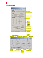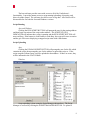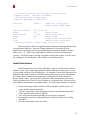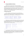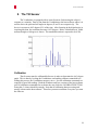
1
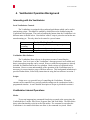
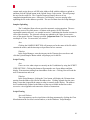
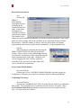
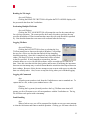
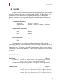
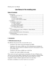
GVE-12-GVS-M01
The Vestibulator
USER MANUAL
Updated September 10, 2012
GVE-12-GVS-M01
Table Of Contents
1. Features.........................................................................................................................3
2. Overview .......................................................................................................................4
3. Setup..............................................................................................................................4
4. Vestibulator Operation Background..........................................................................5
Interacting with the Vestibulator .............................................................................5
Vestibulator Internal Operations..............................................................................5
Electrode Currents ...................................................................................................6
5. Vestibulator Host Software.........................................................................................7
Running the Software ..............................................................................................7
The User Interface....................................................................................................8
6. Scripts..........................................................................................................................14
Instruction Set ........................................................................................................14
A Sample Script .....................................................................................................15
Invalid Instructions ................................................................................................16
7. Samples (Matlab Interface).......................................................................................17
A Sample Samples file...........................................................................................17
8. The Tilt Sensor ...........................................................................................................18
Calibration..............................................................................................................18
9. Keyboard Shortcuts ...................................................................................................19
10. Communication Errors .............................................................................................20
11. Quick Reference .........................................................................................................21
Startup ....................................................................................................................21
12. Vestibulator to Brainbox Settings ............................................................................22
2
GVE-12-GVS-M01
1. Features
•
•
•
•
•
•
Built-in Tilt Sensor
Direct Manual stimulations
User-defined Scripts (with automatic compilation)
Non-volatile Script Memory
Local control enabling subject to execute scripts
Easy to use computer interface
o Windows and Java versions available
o Intuitive Graphical User Interface
o Command and data logging
o Automatically compiles scripts when uploading
o Can generate, compile and upload a script using sampled data
o Optional low-level interface for debugging
3
GVE-12-GVS-M01
2. Overview
The Vestibulator is a device which is used to stimulate the human vestibular
system by injecting small currents behind the ears of a person. It consists of a small box
designed to be fastened to a person’s body with 4 leads protruding outward used to attach
behind the ears. An RS-232 serial link, with a null modem is used to connect the
Vestibulator to a nearby computer which is used to control the device and acquire data.
A push button on the Vestibulator can be used to arm, run, and stop scripts locally.
3. Setup
Connecting the Vestibulator to a Computer
The Vestibulator must be connected to the serial port of a computer with a
standard serial cable,including a null modem.
Mounting the Vestibulator
The proper and safe attachment of electrodes to a human body is beyond the
scope of knowledge of the developers.
Turn the vestibulator unit switch on, prior to fixing electrodes on subject.
Neglecting this step will not cause any damage to either the unit or the subject, but a
small initial transient signal could occur.
Installing The Host Software
Both versions are fully compiled and don’t require a system installation.
However, the Java version requires the Java Platform (provided for free at
http://java.sun.com) as well as the javax.comm package which may not be installed by
default with your Java installation. A Windows version of this package is included in the
javaxcomm folder with this software. To install it, simply follow the instructions in
INSTALL.txt.
The Windows software should be runnable right away. It uses only the standard
Windows dll files. No installation of this software is necessary. Just copy the folder to
the destination of your choosing.
4
GVE-12-GVS-M01
4. Vestibulator Operation Background
Interacting with the Vestibulator
Local Vestibulator Controls
The Vestibulator is equipped with an onboard push button which can be used to
arm/run/stop scripts. This button is enabled by default but can be disabled using the
Vestibulator Host program. The result of pushing the button when the Vestibulator is in
different states is shown below. Note that an “armed” script is poised to run but has not
started running yet. The only other local control is a power button.
State
No script armed
or running
Script is armed
Script is running
Result of Pushing Local Button
Arms the script at 0x000 assuming a script is there
Runs the currently armed script
Stops the currently running script
Vestibulator Host Software
The Vestibulator Host software is the primary means of controlling the
Vestibulator. Low level specs of the Vestibulator’s message protocol are available and
hence custom host programs can be created. However robust host programs are already
included for Windows and for the Java platform. Both versions are explained in this
document. However some understanding of the operation of the Vestibulator may be
necessary for a more intuitive grasp of the host software. This background information is
provided further below, followed by instructions in using the host software in section 5.
Scripts
Scripts are a very powerful way of controlling the Vestibulator. Electrode
currents can be controlled very precisely and tilt readings can be synchronized with a
programmed stimulus. A more detailed description of scripts is provided in section 6.
Vestibulator Internal Operations
Modes
To prevent inappropriate commands from being executed at the wrong time, the
Vestibulator has 5 modes: Idle, Direct, Program, Run, and Fault Mode. The table below
shows what functionality exists in each of the modes. If a command is sent when the
Vestibulator is in a mode which does not allow it, the command is rejected. Mode
5
GVE-12-GVS-M01
switching is often done automatically by the host software, but for safety reasons must
sometimes be done by the user manually (e.g. in Fault Mode). A summary of the
functionality allowed in each mode is shown in the table below.
Electrode
Script
Script
Tilt
Mode Interactions Uploading Running Sensing
Idle
No
No
No
Yes
Direct
Yes
No
No
Yes
Program
No
Yes
No
Yes
1
Run
No
No
Yes
No1
Fault
No
No
No
No
1) Control through the Host software is not allowed but access is available
using script commands.
Faults
Faults can occur in the Vestibulator from communication errors, script errors, or
internal errors. When a fault occurs the electrodes are set to zero and the Vestibulator
attempts to recover (if appropriate). If this fails, the Vestibulator will remain in Fault
mode. Instruction on how to handle a Fault can be found in section 5.
Electrode Currents
The electrodes can emit currents between –2.56 and +2.54 mA inclusive. The
currents are represented with a single byte (8-bits). Thus the allowable range is between
0 and 255. The byte is translated into a current via the following equation:
Current (mA) = (byte * 0.02) – 2.56
Thus a value of 128 yields a zero current, 0 yields the most negative current of 2.56 mA and 255 yields the highest positive current of 2.54. Actual measurements
indicate that the zero current occurs closer to 127. A summary of measured currents is
provided in the table below.
Byte Value
0
127
128
255
Nominal
Current (mA)
-2.56
-0.02
0.00
2.54
Measured
Current (mA)
-2.57
0.00
0.02
2.59
6
GVE-12-GVS-M01
5. Vestibulator Host Software
Running the Software
Windows
To run the Windows host software, simply execute the file vestib.exe.
Doing so will assume that the Vestibulator can be found on COM1. If the Vestibulator is
on another communications port, you must specify the port number in the command line
as follows:
vestib 2
Which would use COM2. Most machines will use COM1
Java
To run the Java host software you can run the following command from within
the Java/classes directory of the software:
C:\j2sdk1.4.1_03\bin\javaw –cp . Vestib COM1
Replacing C:\j2sdk1.4.1_03 with the directory of your Java installation and COM1 with
the name of your communications port (eg. COMx for Windows, /dev/ttyx for Unix, etc).
If you do not specify a communication port, “COM1” is assumed. If you would like to
see the serial link activity and other debug information, use:
C:\j2sdk1.4.1_03\bin\java -cp . Vestib COM1
The following errors indicate something’s wrong with your installation of the
javax.comm. package.
NoClassDefFoundError: javax/comm/CommPort
Cause: missing comm.jar
javax.comm.NoSuchPortException
Cause: missing javax.comm.properties
java.lang.UnsatisfiedLinkError
Cause: missing library file (win32com.dll for windows)
If any of these problems occur, be sure to read over INSTALL.txt again
(carefully) and ensure the files have been copied to the correct directories. Or double
check your previous javax.comm installation.
7
GVE-12-GVS-M01
The User Interface
8
GVE-12-GVS-M01
The host software provides users with access to all of the Vestibulator’s
functionality. It provides instant access to script running/uploading, tilt sensing, and
direct electrode control. The software also allows users to log data. All of these will be
discussed below for both the Java and Windows versions.
Script Running
Java and Windows
Clicking the RUN SCRIPT BUTTON will prompt the user for the starting address
and then begin execution of the script at that address. The SCRIPT STATUS
INDICATOR will indicate that a script is running and the RUN SCRIPT BUTTON will
now read Stop. If the button is clicked while it reads Stop, the script will cease execution
and the gui will reset to displaying a stopped script status with a Run button.
Script Uploading
Java
Clicking the UPLOAD SCRIPT BUTTON will prompt the user for the file which
contains the script, then prompt the user for the address to upload the script to. If the
script compiles without errors it will be uploaded to that address. If there are errors, they
will be indicated in the STATUS BAR.
Windows
Script uploading is done using the Script Manager shown above. The Script
Manager is accessed by clicking the SCRIPT MANAGER BUTTON. To upload a
9
GVE-12-GVS-M01
custom made script, the user will fill in the Address field with the address to upload to,
and then click the Upload button in the Upload Source Code section. This will prompt
the user for the script file. The Compiler Output will notify the user of any
compilation/transmission errors. Otherwise it will display a success message after
uploading the file to the addresss specified. The user can then close the Script Manager.
Samples Uploading
The Vestibulator Host software provides automatic script generation. The user
need only create a file which stores a 4-column wide matrix (in ASCII decimal,
exponential notation allowed – see sample in section 7) indicating the absolute currents in
each of the electrodes. The electrode currents are updated to the values in successive
rows of the matrix after the Timestep specified. Important Note: The Timestep must be
a multiple of 25 ms. For more info, see section 7.
Java
Clicking the SAMPLES BUTTON will prompt you for the name of the file which
contains the matrix, and the timestep to elapse between new currents.
Windows
In the Script Manager, enter the timestep in the Timestep box seen above and
click the Upload Samples Button which will prompt you for the file.
Script Viewing
Java
Users can view what scripts are currenly on the Vestibulator by using the SCRIPT
VIEW BUTTON. Clicking this button will prompt the user for an address and then
display 20 instructions starting from that address to the user. Clicking Next will read the
next 20 instructions and so on.
Windows
In the Script Manager, clicking the View button will display the 20 instructions
starting from the address specified in the address box. Clicking Append does the same
thing, except that it appends the output to what is currently in the display. The address
box is automatically updated to the address of the next available instruction so that
successive views/appends read consecutive blocks of instructions.
Script Clearing
Java and Windows
The script memory can be wiped clean with Stop statements by clicking the Clear
Mem button on the Java host’s main window, or in the Windows’ Script Manager.
10
GVE-12-GVS-M01
Direct Electrode Control
Java
Clicking the
DIRECT
ELECTRODE
CONTROLS button
will bring up the
controls shown to the
right. As the sliders
are dragged, the
electrode currents are
automatically updated.
The cleanest way to
change the current without any transients is to use the keyboard commands. Click on the
slider you want to change and use the Up/Down arrows along with the Page Up/Page
Down buttons. When the window is closed, or the user selects Done, the currents
maintain their values (unless a mode switch is initiated by a script run/upload/view).
Windows
The electrodes are controlled directly using the
DIRECT ELECTRODE CONTROLS on the main
window. These controls will be enabled only when the
user places the Vestibulator in Direct mode by using the
menu command shown to the right. Unlike the Java
version, dragging the slider will only update the
electrodes at the value where the slider lands (after
you’ve released the mouse button).
Local Control Enable/Disable
Java and Windows
Clicking the LOCAL CONTROL ENABLE/DISABLE checkbox toggles the
Vestibulator’s willingness to accept local commands from the onboard push button.
Calibrating Tilt Sensors
Java and Windows
Clicking the CALIBRATE BUTTON will update the host with 10 new calibration
data packets. The orientation of the Vestibulator becomes the new zero plane. Hence,
the Vestibulator must be level such that it would read a tilt of zero degrees on both
axes. See section 8 for more details.
11
GVE-12-GVS-M01
Reading the Tilt Angle
Java and Windows
Clicking the READ TILT BUTTON will update theTILT ANGLES display with
the present tilt data from the Vestibulator.
Performing Multiple Tilt Reads
Java and Windows
Clicking the TILT LOOP BUTTON will prompt the user for the count and step
for a tilt loop operation. The count specifies how many tilt reads to perform, the step
specifies the number of 25ms increments that consecutive tilt reads should be separated
by. Note that this button does not return a tilt read until after the first step.
Logging Tilt Data
Java and Windows
Clicking the LOG BUTTON in Java or selecting the Log
Tilt Data menu item as shown to the right in Windows, will prompt
the user for a file to save the data into and ask if time stamping
should be turned on. Once this is completed, any tilt readings from
either a Tilt Read, Tilt Loop, or script instruction will be recorded
in the file specified. If time stamping was turned on, the time
when the data was received by the host software will be recorded next to each row of
data. Note, this is not the time the data is taken, and because of buffering, the increment
between two timestamps may even be different then the actual time that elapsed between
their readings. Because of this, the time stamps are not accurate with respect to when the
data was actually taken. Also, be sure to stop the tilt log when you’re finished logging.
Logging All Commands
Java
All packet sent to and received from the Vestibulator are sent to standard out. To
capture this to a file, redirect your standard out to a file.
Windows
Clicking the Log menu (located just above the Log Tilt Data menu item) will
prompt you for a file name to save all correspondence with the Vestibulator to. The log
file will show each packet with a timestamp.
Fault Handling
Java
When a fault occurs, you will be prompted for whether or not you want to attempt
to clear the fault status and return to normal operation. Clicking yes will most often do so
12
GVE-12-GVS-M01
successfully, if not, the program will terminate. Choosing no does nothing, leaving the
Vestibulator in Fault mode.
Windows
A message will popup alerting you of the fault, and suggesting you send the
‘Clear Fault Status’ command. This command can be found in the Command menu.
13
GVE-12-GVS-M01
6. Scripts
Scripts allow users to stimulate a subject and take tilt readings in a synchronized
and precise manner. All scripts are written in a plain text file. The host software will
automatically convert source code to compiled bytecode which can be uploaded.
Because of this, there is no need to store scripts in a form other than their source code.
The script syntax is very simplified and consists of only 9 instructions shown below.
Vestibulator Instructions
Setelectrode
Setallelectrodes
Tiltloop
<electrode> <current>
<current1> <current2> <current3> <current4>
<count> <step>
Script Control Instructions
Stop
Goto
<address>
Call
<address>
Return
Other Instructions
Delay
NOP
<delay>
All commands are case insensitive and comments can be added using the ‘;’
(semi-colon) character. When a semi-colon is found, all text up to the end of the line is
ignored by the compiler. All commands, arguments, and comments must be separated by
white spaces only. No commas or any other punctuation aside from the semi-colon for
commenting is allowed in the document. A more detailed description of the instruction
set follows.
Instruction Set
Setelectrode
Parameters:
(3 bytes)
electrode – a number between 1 and 4 specifying the electrode
current – the new current value between 0 and 255
Sets the electrode specified by ‘electrode’ to output the current specified by
‘current’.
Setallelectrodes
Parameters:
(5 bytes)
current1 – the current between 0 and 255 to assign to electrode 1
current2 – the current between 0 and 255 to assign to electrode 2
current3 – the current between 0 and 255 to assign to electrode 3
current4 – the current between 0 and 255 to assign to electrode 4
14
GVE-12-GVS-M01
Sets electrodes 1, 2, 3 and 4 to output the currents given by current1, current2,
current3, and current4 respectively.
Tiltloop
Parameters:
(4 bytes)
count – the number of tilt reads to perform between 0 and 65535
step – the number of 25ms ticks to wait between successive tilt
reads (between 0 and 255)
Performs ‘count’ tilt reads each ‘step’ 25ms increments apart. A value of 0 is not
appropriate for either parameter, instead a zero is interpreted as the maximum value plus
one (65536 for count, and 256 for step). The first tilt read doesn’t occur until after one
‘step’.
Stop
(1 byte)
Parameters: none
Halts the currently running scripts, zeroing the electrodes, and terminating
Tiltloops.
Goto (3 bytes)
Parameters: address – the address to jump to between 0 and 2047
Starts running the script at ‘address’.
Call
(3 bytes)
Parameters: address – the address to jump to between 0 and 2047
Starts running the script at ‘address’ storing the return value on an 8 word deep
stack.
Return
(1 byte)
Parameters: none
Pops the topmost value off the stack and resumes execution at that address.
Delay (3 bytes)
Parameters: delay – the number of 25ms ticks to delay between 0 and 65535
Suspends execution of the script for a time period equal to the product of the
specified ‘delay’ and the script clock period (currently 25 milliseconds).
NOP (1 byte)
Parameters: none
Null instruction, wastes a cycle.
A Sample Script
Below is an example of a simple script which oscillates one of the probes while
taking tilt readings on each clock cycle.
15
GVE-12-GVS-M01
;
;
;
;
=================== Start Script ===============
Sample Script – Infinite dizziness
written by Peter Yiannacouras
Must be uploaded to address 0
Tiltloop
2000 1
;read tilt every cycle
;keep reading 2000 times
Setallelectrodes
255 0 235 20
Delay
10
;delay 250ms
Setelectrode
3 128
;zero electrode 3
Delay
20
;delay 500ms
Goto
4
;loop to Setallelectrodes
Stop
;should never reach here
; =================== End Script ===============
In the script above the Goto statement jumps to address 4 assuming that the script
was uploaded to address 0. Since the Tiltloop statement is 4 bytes long (see the
Instruction Set section previously), the Setallelectrodes instruction should be found at
address 4 (0 + 4). If the script is uploaded to a different location, it will not behave
correctly. It will still jump to location 4 regardless of what code is there, even if it is not
the starting byte of an instruction. This could be an invalid instruction.
Invalid Instructions
Invalid instructions can arise from uploading a script to a location where there is
already a script. If the script being uploaded is shorter than the one there, there is a risk
of overwriting only part of an old instruction. For example if a lone NOP instruction was
uploaded to the same location as a Setallelectrodes instruction, the 4 bytes that make up
the currents for the Setallelectrodes instruction would follow the NOP instruction.
Because NOP is only 1 byte long, these parameters will be interpreted as instructions
which will either cause a Fault, or worse, disguise as valid instructions. Because of this
care should be taken whenever uploading scripts. The following precautions are advised:
1. Do not write scripts which are meant to follow through to another script. All
scripts should terminate themselves.
2. View the script memory after uploading to check for invalid instructions (they
will be specified in the viewer’s display).
3. View script memory before uploading to avoid script overlapping.
4. Be prepared to overwrite invalid instructions with more code, or a set of Stop
commands.
5. Clear the script memory once in a while.
16
GVE-12-GVS-M01
7. Samples (Matlab Interface)
Samples allow users to abstract from the details of the Vestibulator’s
implementation and its accompanying software. As mentioned previously, the electrodes
emit between –2.56 mA and +2.54 mA of current. Users can enter their desired currents
within this range into a text file in the format of a 4 column-wide matrix. This file can be
used to generate and upload a script as described in Section 5. The user must specify a
timestep which indicates the time delay to elapse between assigning currents in
successive rows. Since the Vestibulator scripts work on a 25ms clock, timesteps must be
a multiple of 25ms. An example is shown below.
A Sample Samples file
Below is a sample of a 4 column wide matrix that can be uploaded to the
Vestibulator. Note that comments are not allowed in a samples files, the only thing that
can be in the file is the 4-column wide matrix. The program can read data exported from
Matlab in ascii mode (eg. Via the command “save -ascii currents.txt cur”).
;=============== Start Samples ==================
0.0000e+000 -2.5600e+000 2.5400e+000 4.0000e-001
1.0000e+000 -1.0000e+000 1.5000e+000 -1.5000e+000
0.0200e+000 -0.0200e+000 0.0400e+000 -0.4000e-001
;=============== End Samples ====================
When this script is compiled and uploaded with a specified timestep T, delays will
be inserted appropriately between the “rows”. When the script is run, the electrodes will
have the values in the first row (0, -2.56, 2.54, 0.4) for T milliseconds. Then the values
will change to those of the second row, and so on. The code produced from these
samples is shown below for a timestep of 150ms.
;=============== Start Generated Script ==============
SetAllElectrodes
128 0 254 148
Delay
5
SetAllElectrodes
178 78 203 53
Delay
5
SetAllElectrodes
129 127 130 126
Delay
5
Stop
;=============== End Generated Script ================
Note that the delay is 5 instead of 6 (150/25ms) to account for the 25ms added for
processing the SetAllElectrodes instruction itself. If the timestep was specified as 25ms,
no delay instructions would have been inserted. A Stop instruction is always appended to
the end of the script. One can use the script viewer to find and overwrite the stop
command with more appropriate code.
17
GVE-12-GVS-M01
8. The Tilt Sensor
The Vestibulator is equipped with its own tilt sensor for detecting the subject’s
response to a stimulus. Data is sent from the Vestibulator to the host software where it is
used to derive the pitch and roll angles in degrees (X and Y axes respectively). The
device is accurate to 0.45 degrees 95% of the time. After factoring in the digital noise in
acquiring this data, the resolution becomes 0.655 degrees. Below a distribution of 10000
measured angles at 0 degrees is shown. The standard deviation is reported to be 0.294.
Calibration
The tilt sensor must be calibrated before use in order to determine the (0,0) degree
angle. This is done by leveling the Vestibulator, and sending calibrate commands to it.
During this process, the Vestibulator must not move. Several calibration commands are
required for good tilt readings. Both the Windows and Java versions of the host software
send 10 calibration commands for each time the user clicks the CALIBRATE BUTTON.
Doing this 3-4 times should be enough. Note that all calibration data processing and
storage is done on the host software. Therefore you must recalibrate every time you start
the software.
18
GVE-12-GVS-M01
9. Keyboard Shortcuts
Below is a list of the keyboard shortuts available in the Windows version. The
Java version does not currently support keyboard shortcuts.
Ctrl + A
Ctrl + D
Ctrl + I
Ctrl + P
Ctrl + R
Alt + B
Alt + E
Alt + L
Alt + M
Alt + R
Alt + T
Toggles display of advanced windows
Direct Mode
Idle Mode
Program Mode
Run Mode
Calibrate
Clear advanced windows
Tilt Loop
Script Manager
Run Script
Read Tilt
19
GVE-12-GVS-M01
10. Communication Errors
Ideally the only communication error users will be faced with will be caused by
the Vestibulator not being turned on. However other communication errors can arise.
Receive Rate Too Fast
If you send too many commands in too short of a time to the Vestibulator, an
overrun error will occur. You will receive an mdgRxRateTooFast message (which you
can see in the debug output) and the Vestibulator will go into Fault mode.
Bad Packet Start
Every command and message sent to/from the Vestibulator must start with a
special byte. If this byte is not the first thing received by either the Vestibulator or the
Host, an error will occur. If it is the Vestibulator that received it, it will send an
mdgExpectedSOC message and ignore it. The host will similarly alert the user about the
problem (in the status bar or commandline) and ignore it.
Receive Timeouts
If the host is awaiting a response and does not receive it in a reasonable length of
time, it will time out and often terminate. Note that the Java version expects a response
with all commands, while the Windows version rarely does. The completion of a
command is verified by receiving the mdgAccepted message. This is enforced by the
Java program but not the Windows. Users can manually assert the completion of a
command by viewing the mdgAccepted message in the Debug Windows.
The Vestibulator can also timeout when it receives the start of a packet but not the
rest of it in a reasonable length of time. This can be caused by the Vestibulator or host
being too busy.
20
GVE-12-GVS-M01
11. Quick Reference
Startup
1. Start the host software as described in section 5.
2. Turn on the power button on the Vestibulator
3. Click the CALIBRATE BUTTON at least 3-4 times
4. Carry on with your own operations
21
GVE-12-GVS-M01
12. Vestibulator to Brainbox Settings
Brainboxes BL830 Bluetooth devices
14Sep2006
==================================
Setup program settings
---------------------Current settings
................
Baud rate
9600
Parity
none
Stop bits
1
PIN code
1234
Client/server -- need 1 server with no partner set
+
1 client with partner device address set
to the server's device address
Advanced settings
.................
Discoverability
on
Security mode
3
Encryption
disabled
Switch role
off
Class of device
Peripheral
Hand shaking
none
Connect scheme
proximity off
Low power mode
disabled
Interactive menu on
Then "Apply"
Use
--We've been connecting the "server" unit to the PC and
the "client" unit to the Vestibulator.
We've been starting up the PC software before turning
the Vestibulator on.
We haven't checked out all the other possible permutations.
22
GVE-12-GVS-M01
Electrode Wire
==============
Black - common
Red - channel 1
Green - channel 2
Blue - channel 3
White - channel 4
Brown - not used
23