1
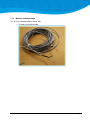
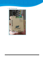
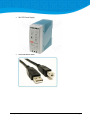
iSii aqua compact installation manual Version date: November 11, 2013 Release version: 1646 This document has been created with utmost care. Given the scope of its content and the complexity of the matter Hoogendoorn Growth Management is not responsible for the correctness of this document. Terms of delivery Mailing Address: Visiting Address: PO Box 108 Westlandseweg 190 NL - 3130 AC Vlaardingen The Netherlands Telephone: +31 10 4608080 E-mail: [email protected] RIGHTS. Copyright © Hoogendoorn Growth Management, Vlaardingen, The Netherlands 2011. All rights reserved. Names with ® are registered trademarks of Hoogendoorn Growth Management. TERMS OF DELIVERY The General Terms of Delivery of Installation Companies of 2007 (ALIB 2007) as laid down by Uneto-VNI, apply to all our contractual relationships. On your request, these terms will be sent to you immediately and free of charge. They can also be read in the Help function of your Hoogendoorn computer and on the Internet: www.hoogendoorn.nl In addition, the contractual or general terms of your Hoogendoorn dealer or installer may also apply. In the event of any conflict between terms, the terms of the dealer/installer will prevail. UNDISTURBED FUNCTION In addition to the ALIB 2007 General Terms of Delivery, there are two extra provisions concerning the iSii Aqua Compact process computer: 1. Do not run or install any other software on the iSii Aqua Compact than provided by Hoogendoorn, unless Hoogendoorn has specifically declared this third party software “appropriate for Hoogendoorn”. 2. The iSii Aqua Compact should only be connected to a computer network (LAN, WAN, Internet etc.) by a skilled and professional IT supplier who strictly follows the Hoogendoorn guidelines on this matter. These guidelines can be obtained free of charge at the Hoogendoorn helpdesk. Unless both of these items are observed properly, Hoogendoorn will not be responsible for any possible consequences. PUBLICATIONS Every effort has been made to ensure the accuracy of the contents of this publication and the computer program described. Should any errors be detected, Hoogendoorn would greatly appreciate notification. Notwithstanding the above, Hoogendoorn can only accept liability for any damage or for the consequences thereof, as described in the above-mentioned General Terms. The contents of this document are subject to change without notice. EXTRA PROTECTION You should not rely on critical processes to be guarded and protected by means of your computer alone. There are many critical processes in a greenhouse - like watering, levelling of peaks in 2 gas and electricity consumption, CO supply, lighting, etc. – which need to be safeguarded. We strongly advise you to provide for back-up protection by means other than a computer through equipment unconnected to or independent of the process computer. Above that, personal (visual) checks of vital processes should be performed regularly. Furthermore, precautions outside the computer must be implemented to prevent from damage to installations due to erroneous or unexpected computer actions. iSii aqua compact installation manual Terms of delivery 3 Contents 1 QUICK START.....................................................................................................................................7 1.1 STEP 1 REQUIREMENTS ...............................................................................................................................7 1.2 STEP 2 PREPARATION .................................................................................................................................8 1.2.1 Connect the hardware ....................................................................................................................8 1.3 STEP 3 ACTIVATION ................................................................................................................................. 13 1.4 STEP 4 CONFIGURATION........................................................................................................................... 14 1.4.1 What is configured? .................................................................................................................... 14 1.5 QUICK START CONCLUSION....................................................................................................................... 15 1.5.1 Note when operating .................................................................................................................. 15 2 AFTER ACTIVATION CHECK............................................................................................................... 17 2.1 CHECK CONTROL INSTANCES...................................................................................................................... 17 2.1.1 How to rename control instances ............................................................................................... 18 2.1.2 More information control instances............................................................................................ 18 2.1.3 Need more control instances? ..................................................................................................... 18 2.2 CHECK IO HARDWARE CONFIGURATION ...................................................................................................... 18 2.2.1 Step 1: Go to the 'Manage' tab and select 'Open IO Configuration page'. ................................. 18 2.2.2 Step 2: Configure your iSii aqua compact hardware ................................................................... 20 2.2.3 Optional: weather station ........................................................................................................... 20 2.3 I/O CONNECTIONS .................................................................................................................................. 21 2.3.1 View connections......................................................................................................................... 21 2.3.2 Add or change connections ......................................................................................................... 21 2.3.3 Check connections ....................................................................................................................... 22 2.4 CONNECT CONTROLS ............................................................................................................................... 25 2.4.1 Controls to connect ..................................................................................................................... 25 2.4.2 Connect Irrigation Valve to an Irrigation Pump .......................................................................... 26 2.4.3 Filtered view of the connection page .......................................................................................... 27 2.5 SET TIME AND TIME ZONE ......................................................................................................................... 28 2.6 AFTER ACTIVATION CHECK CONCLUSION ...................................................................................................... 29 3 CONNECT HARDWARE ..................................................................................................................... 31 4 I/O WORKBENCH............................................................................................................................. 33 4.1 4.2 4.3 4.4 5 SENSOR PRESET....................................................................................................................................... 33 OFFSET AND CONVERSION MATRIX ............................................................................................................. 34 GRAPH SELECTED IO ................................................................................................................................ 34 IO WORKBENCH CONCLUSION................................................................................................................... 34 BACKUP AND RESTORE .................................................................................................................... 35 5.1 5.2 BACKUP ................................................................................................................................................. 35 RESTORE................................................................................................................................................ 36 iSii aqua compact installation manual Contents 4 6 MANAGE......................................................................................................................................... 37 6.1 OPTIONS MANAGE TAB ............................................................................................................................ 37 6.2 CONTROL INSTANCES ............................................................................................................................... 38 6.2.1 How to add control instances ...................................................................................................... 38 6.2.2 How to remove control instances ................................................................................................ 39 6.3 CONFIGURE NETWORK ............................................................................................................................. 39 6.4 UPDATE PAGE ......................................................................................................................................... 43 6.5 IMPORT NEW LICENSE .............................................................................................................................. 44 6.5.1 Step 1 ........................................................................................................................................... 44 6.5.2 Step 2 ........................................................................................................................................... 44 6.5.3 Step 3 ........................................................................................................................................... 44 7 HOW TO COMMISSION CONTROLS .................................................................................................. 45 7.1 HOW TO COMMISSION AN EC CONTROL...................................................................................................... 45 7.1.1 I/O: inputs (Ain) ........................................................................................................................... 46 7.1.2 I/O: Digital outputs (Dout) .......................................................................................................... 46 7.1.3 I-action calculation ...................................................................................................................... 47 7.1.4 I-action realization ...................................................................................................................... 47 7.1.5 Modulating system...................................................................................................................... 47 7.1.6 Modulating on-off system ........................................................................................................... 47 7.2 HOW TO COMMISSION THE FERTILIZER RATIO CONTROL ................................................................................ 48 7.2.1 Adding Fertilizer Ratio control(s) ................................................................................................. 48 7.2.2 Connecting Fertilizer Ratio control(s) .......................................................................................... 48 7.2.3 Connecting Fertilizer Ratio control(s) .......................................................................................... 49 7.2.4 Coupling Fertilizer Ratio to IO channel ........................................................................................ 49 7.2.5 IO: inputs (Ain)............................................................................................................................. 49 7.2.6 I/O: Digital outputs (Dout) .......................................................................................................... 50 7.3 WEATHER STATION - OPTIONAL ................................................................................................................. 50 7.3.1 Weather station package ............................................................................................................ 51 7.3.2 Step by step installation .............................................................................................................. 54 7.3.3 Set up the control ........................................................................................................................ 57 8 SYSTEM LAY-OUT ............................................................................................................................ 61 9 NETWORK ARCHITECTURE ............................................................................................................... 63 10 GREENPOINT TERMINAL LAYOUT (BASIC VERSION) ....................................................................... 65 11 APPENDIX 1 ................................................................................................................................. 67 11.1 12 12.1 12.2 12.3 EXTENDED VERSION ............................................................................................................................. 67 APPENDIX 2 ................................................................................................................................. 69 COUNTER INPUTS HA1512 ................................................................................................................... 69 ANALOG INPUTS_4-20MA HA3454 ...................................................................................................... 69 ANALOG INPUTS 0-20MA HA3444........................................................................................................ 71 iSii aqua compact installation manual Contents 5 12.4 ANALOG INPUTS 0-10V HA3464 .......................................................................................................... 72 12.5 ANALOG OUTPUTS 0-20MA HA4012 .................................................................................................... 73 12.6 UNIVERSAL AC/DC (HA9190).............................................................................................................. 74 12.7 DIGITAL OUTPUTS MOSFET HA2784 ...................................................................................................... 75 12.8 VALVES .............................................................................................................................................. 76 12.9 M950 ............................................................................................................................................... 76 12.10 EXTENSION KIT .................................................................................................................................... 78 12.10.1 HA9020 .................................................................................................................................... 78 12.10.2 HA9050 .................................................................................................................................... 79 12.11 WEATHER STATION - DIAGRAM OF CONNECTIONS ..................................................................................... 80 12.11.1 Connection supplied cable ....................................................................................................... 81 12.11.2 Extending connection cable ..................................................................................................... 81 12.11.3 USB connection cable .............................................................................................................. 81 iSii aqua compact installation manual Contents 6 1 Quick Start The iSii aqua compact is a plug & play system. This means that a great part of the installation, the software part, of the system is done automatically. Get started and follow the next 4 steps! 1.1 Step 1 Requirements Before you start, check if all items in the list below is present. Some items (*) you need to purchase yourself. iSii aqua compact Greenbox The actual computer inside the iSii aqua compact. Power outlet Switch * iSii aqua compact installation manual Quick Start 7 Laptop * WiFi * Network cables * Login information (send by mail) MAC address (will appear once you've logged in) Activation File (send by mail) 1.2 Step 2 Preparation 1.2.1 Connect the hardware It's now time to connect the hardware to each other. iSii aqua compact installation manual Quick Start 8 A. Insert the plug into the outlet B. Connect the greenbox to the switch with a network cable Use LAN1 of the greenbox C. Connect your laptop to the same switch with a network cable D. Switch the power of the greenbox on by switching the 'Main' and 'IO' module upwards on the poweroutlet. 1.2.1.1 How to change network settings step by step A.Go to your Control Panel via the 'windows' button B. Go to 'Network and Internet' iSii aqua compact installation manual Quick Start 9 C. Go to 'Network and Sharing Center' D. Select in the left menu 'Change adapter settings' E. Right-click on the connection you want to use and select 'Properties' F. Click on 'Internet Protocol Version 4 (TCP/IPv4)' and select 'Properties' iSii aqua compact installation manual Quick Start 10 G. Before you change the network settings, write down the original settings so in the end the laptop can be changed back into its original settings. iSii aqua compact installation manual Quick Start 11 H. Now you can change your network settings! Set up communication between the laptop and greenbox In order to connect the laptop with the greenbox, you need to temporary change the network settings of the LAN connection of your laptop. Your laptop needs to be in the same IP address range as the Greenbox. The IP address of the greenbox is by default 10.10.10.10. The IP address of your laptop therefore need to be 10.10.10.11. 1.2.1.2 1.2.1.3 Optional: Connect your laptop to a WiFi network iSii aqua compact installation manual Quick Start 12 NOTE! If you don't have a WiFi network you could use a USB device to download and save the activation file and insert it into your laptop. 1.3 Step 3 Activation When the hardware is connected, it's time to activate your greenbox and make it ready to operate. Follow the next steps to do so. A. Go to your internet browser. Note: To get the most out of the system, it's best to use Google Chrome. B. Go to the activation page Wait for 60 seconds C. Login Your login information was send to you by email. If you haven't received it, please contact us via [email protected]. Note that our helpdesk is only available from Monday to Friday 8:00 am - 5:00 pm (UTC +1) iSii aqua compact installation manual Quick Start 13 D. Once logged in, the activation page will appear with the MAC address. Email the MAC address to [email protected] Note that our helpdesk is only available from Monday to Friday 8:00 am - 5:00 pm (UTC +1) E. Hoogendoorn will email you the activation file. Open your email, download the file and save it to a folder you can easily find. F. Login and open the activation page and click on 'choose file'. Go to the folder where you saved the activation file. Select 'submit'. Wait for 5 minutes while the configuration takes place. 1.4 Step 4 Configuration After 5 minutes the home screen will appear and the configuration is automatically done! 1.4.1 What is configured? Activating system Controls added IO modules added Connection of controls to IO modules iSii aqua compact installation manual Quick Start 14 Connection between controls 1.5 Quick Start Conclusion When the automatic configuration is done, you can take the followings steps: 1.5.1 [recommended] Check the configuration > Chapter "After activation check" Connect the hardware > Chapter "Connect hardware" Backup your system > Chapter "Backup and restore" Note when operating Note that when setting parameter values, the correct separation characters are used. For example Use the ":" when you need to insert time as "h:m:s". 1.5.1.1 Editing values Values with a “pencil” button are editable by users. When the “pencil” button is pressed a user is able to change the setting value. After clicking the green button the edited value is saved. The content of the page is refreshed every second. Setting values that are in edit mode are not refreshed. The parameters of all control pages are sorted in alphabetical order. iSii aqua compact installation manual Quick Start 15 All actions described in this document can only be done when you are logged in as "AquaService". iSii aqua compact installation manual Quick Start 16 2 After activation check The configuration is done automatically when you have followed the steps in chapter "Quick Start". It is recommended to check the system after the activation. 2.1 Check control instances Click on the icon or scan the QR code to view the supporting video Browse to the 'Manage' page and click on ‘Open control instances page’, a page opens that looks like the image below. The upper part of the page is meant for adding new control instances. The lower part offers a survey of all current control instances. On this page you can check if all control instances are connected. iSii aqua compact installation manual After activation check 17 2.1.1 How to rename control instances 1. In the report of existing control instances (lower part of the screen), select the control instance you want to rename by clicking on it; (1) 2. In the box with the 'control name' write the new instance name; (2) 3. Click on the 'rename selected' button. (3) 2.1.2 More information control instances More information on how to add and remove control instances, go to Paragraph "Control instances". 2.1.3 Need more control instances? Contact your dealer when you want or need more control instances. You will receive a new license which you can import into your system. See also paragraph "Import new license". 2.2 Check IO hardware configuration It's necessary to check if the IO Hardware configuration is in sync with the hardware inside the greenbox. Just follow the next steps to do so. 2.2.1 Step 1: Go to the 'Manage' tab and select 'Open IO Configuration page'. iSii aqua compact installation manual After activation check 18 iSii aqua compact installation manual After activation check 19 The page shown below opens. The upper modules are an overview of inactive modules. The modules below that are active in your iSii aqua compact. 2.2.2 Step 2: Configure your iSii aqua compact hardware You can configurate every Greenpoint module to make it in sync with the actual hardware in the greenbox by selecting them and dragging them in the area (active or inactive modules) and position you wish. You can also delete a module by selecting them and dragging it into the bin. Note! - Software and hardware must be in sync - Switch off the IO power switch to (de)install IO modules. 2.2.3 Optional: weather station You can also add the weather station compact to your system. How to set up this control you can find in paragraph "weather station", the setup of the hardware you can find in paragraph "weather station - diagram of connections". When you purchase the weather station later, you will receive a new license. You can find how to import the new license in paragraph "import new license". iSii aqua compact installation manual After activation check 20 2.3 I/O Connections Introduction When you are logged in you can view the I/O Connections tab. Here you can view, check and change the connections of the control parameters to physical IO hardware addresses. 2.3.1 View connections Click on the 'I/O connections' tab in order to check the inputs and outputs. 1. Control type 2. Control instance 3. Parameter 4. Greenpoint unit 5. Greenpoint module 6. Module Channel number 7. Add coupling On this page you can check the entire list of connections. 2.3.2 Add or change connections You can add a connection by selecting the control type (1) and select the module (5) and right channel. Click on 'add new coupling' to add the new connection. If you want to remove a connection, click on the delete button behind the connection. iSii aqua compact installation manual After activation check 21 2.3.3 Check connections When a connection is added, you can check if the connection is working by making the connection active. Follow the next steps to check your newly added connection. 2.3.3.1 Step 1: Add or change your connection (view paragraph before) For example iSii aqua compact installation manual After activation check 22 2.3.3.2 Step 2: Go to IO Workbench and select the IO module and channel of the connection 1. Click on the fourth IO module, HA2784 (see step 1: "4 - ha2784"). Note In the programming language you start counting at 0. So when it says for example "4 - ha2784", you need to pick the 5th connection counting down from the top! 1. Select 'Channel 2' (see step 1: "2 - channel 2") 2. Select 'Manual override' 3. Click on 'Active' and select the green button to activate. 4. At the 'Coupled parameters' you can check if the parameters are the same as the connection you wanted to select. As you can see it has the same parameters as selected at step 1. iSii aqua compact installation manual After activation check 23 2.3.3.3 Step 3: Check the graph 2.3.3.4 Step 4: Check the hardware in your iSii aqua compact Is the light on of the IO module you have connected? iSii aqua compact installation manual After activation check 24 2.4 Connect Controls Introduction You need to connect several controls to each other so that they will work together. For example, the most important condition for irrigation is that the Irrigation Vales are connected to an Irrigation pump. Which connections you need to have or make and how to do that will be explained in this chapter. 2.4.1 Controls to connect The following connections need to be made for the best operation of your iSii aqua compact. 2.4.1.1 Irrigation Irrigation valve Pump control Pump control EC control Pump control pH control Irrigation valve Irrigation Strategy Irrigation valve Drain pit Fertilizer Ratio Pump control 2.4.1.2 Climate Ventilation Control Aspirator Meteo Meteo Compact weather station Solar optimizer Clock and astronomy Wind optimizer Meteo Ventilation, Heating, Climate control Cooling iSii aqua compact installation manual After activation check 25 Climate period Climate control Climate control Aspirator 2.4.2 Connect Irrigation Valve to an Irrigation Pump Click on the icon or scan the QR code to view the supporting video Go to the ‘Connections’ tab. Like we pointed out in the introduction, the most important condition for irrigation is the connection between the Irrigation Valves and an Irrigation Pump. In the ‘Connections’ tab, the Irrigation Valves can be connected to the Irrigation Pumps. When the iSii aqua compact is installed you have given the valves and pumps a name and number, in our example they are given numbers. In the screen above there are four selection fields: 1. Control type, e.g. Irrigation Valve; 2. The specific control instance, e.g. Valve ‘8’; 3. The control type to connect to a valve, in this case the Irrigation Pump; 4. The specific control instance, e.g. Pump ‘1’. iSii aqua compact installation manual After activation check 26 When the correct values are selected in the four selection fields, the ‘add’ button can be pressed. After this event a new connection appears in the table, as seen in the example in 'View, change and check connections'. NOTE 2.4.3 In the next paragraph 'Filtered view of the connection page' you can find how to filter the view. If the valve was already connected to another pump, the current connection is replaced by the new one. Before connecting different valves to pumps, wait until all active irrigation cycles are stopped. Filtered view of the connection page Select the checkbox 'Filter' to filter the view of the connection page, the filter is based on the 'Coupled instance'. iSii aqua compact installation manual After activation check 27 2.5 Set time and time zone To set your time and time zone, go to the 'Manage' tab. You can set the time by clicking on the pencil on the left side of the date. If you want to set the time zone you can click on the icon. iSii aqua compact installation manual After activation check 28 This opens the settings page as shown below. Open the pull down menu for time zones to select the time zone the iSii aqua compact is in. Once you have selected the correct time zone, click on 'change' to save it. When you are done, you need to click the button 'Stop and restart all controls'. The iSii aqua compact is now ready to use! 2.6 After activation check conclusion When you have taken every part of the configuration, you can take the followings steps: [recommended] Check the configuration > Chapter "After Activation Check" Connect the hardware > Chapter "Connect hardware" Commission controls > Chapter "How to commission controls" Backup your system > Chapter "Backup and restore" iSii aqua compact installation manual After activation check 29 3 Connect hardware When you have taken every step in chapters 1 to 3, it is time to connect the inputs and outputs modules to sensors and relais. What to do: What and how to do this you can find in Appendix II. After connecting a sensor to an input channel you need to set up the conversion an calibrate. View chapter "IO Workbench" on how to do this. iSii aqua compact installation manual Connect hardware 31 4 I/O Workbench Click on the icon or scan the QR code to view the supporting video Introduction Go to the I/O Workbench tab to calibrate different devices of the iSii aqua compact, such as sensors. You need to be logged in as a distributor to view this tab. 4.1 Sensor preset iSii aqua compact installation manual I/O Workbench 33 4.2 Offset and conversion matrix 4.3 Graph selected IO 4.4 IO Workbench conclusion When you have calibrated all IO hardware you can continue with one of the next chapters. Commission controls > Chapter "How to commission controls" [recommendation] Make a backup of your system > Chapter "Backup and restore" If you want to start operating the system, go to the user manual. iSii aqua compact installation manual I/O Workbench 34 5 Backup and restore When you are on the Manage page, you can backup and restore backups to your iSii aqua compact. Click on the 'Backup and restore' button. The page below opens. 5.1 Backup Click on 'Create new Backup' to make a backup of your system. The new backup will appear in your list of backups. Note! You can not create more than 2 backups. iSii aqua compact installation manual Backup and restore 35 5.2 Restore To restore a backup you can click on the 'Restore' button of the backup you want to restore. You don't have to pick the last backup, you can also choose an older backup. Note When in doubt, please contact the helpdesk. Restoring may take several minutes iSii aqua compact installation manual Backup and restore 36 6 Manage Introduction At the ‘manage’ page you can view and change the system time, stop and restart all controls and update the iSii aqua compact. 6.1 Options Manage tab Stop and restart all controls Only to be used in case of extreme emergency. System time To set the correct time and time zone manually, can be used if internet is not available. Open update page A link to the update page, can be used for updates via usb stick. Open IO Configuration page To configurate the I/O hardware. Backup and restore It's possible to make back-ups of your system and restore backups when needed. Open control instances page A link to the page where you can add and remove control instances. Configure network Here you can configurate your network, such as your IP address. Import license When you have bought an extension or add-on for your system you will get an new license which you can import here. iSii aqua compact installation manual Manage 37 6.2 Control instances Introduction After you have clicked on ‘Open control instances page’, a page opens that looks like the image below. The upper part of the page is meant for adding new control instances. The lower part offers a survey of all current control instances. 6.2.1 How to add control instances Set the following selection and input fields correctly. Selection field ‘control type’ Select the control type of which you want to add instances. Input field ‘control name’ It is optional to change the text ‘Gr’ to a more relevant text. If you want to add Irrigation valves, for example, you could enter ‘valve {0}’. This would lead to new instances with names like valve 1, valve 2, valve 3 et cetera (while default input ‘Gr {0}’ would lead to instance names like Gr 1, Gr 2, Gr 3 et cetera). Input field ‘start number’ Beware of entering a wrong start number! Enter 1 if no instances of the control type yet exist. If other instances do exist, view all instances of the concerning control type, find the instance with the highest number and enter a start number higher than that. Input field ‘interval’ Enter 1 Input field ‘count’ Enter the number of instances you want to add iSii aqua compact installation manual Manage 38 6.2.2 How to remove control instances 1. In the report of existing control instances (lower part of the screen), select the control instance you want to remove by clicking on it; (1) 2. Click on the ‘delete’ button below the existing control instances report. (2) Note If you add to more control instances then is allowed in your license, such as number of irrigation pump, a notification will pop up. If you click on the icon above 'Home' you will get an excerpt of what went wrong. For example, you can find in the message that a number of 10 irrigation pumps was added when the license is just for 1 irrigation pump. When all is set correctly, click the ‘add’ button and the newly added control instances will appear in the report of existing control instances (lower part of the screen). 6.3 Configure network Before you configure your greenbox, you need to change the network settings on your laptop that you have previously changed in the "Quick Start" chapter "Step 2: Preparation". iSii aqua compact installation manual Manage 39 6.3.1.1 How to change network settings step by step A.Go to your Control Panel via the 'windows' button B. Go to 'Network and Internet' C. Go to 'Network and Sharing Center' D. Select in the left menu 'Change adapter settings' E. Right-click on the connection you want to use and select 'Properties' F. Click on 'Internet Protocol Version 4 (TCP/IPv4)' and select 'Properties' iSii aqua compact installation manual Manage 40 G. Select 'Obtain an IP address automatically' and 'Obtain DNS server address automatically'. When your system needs to be connected to an existing network where IP addresses are different then you need to change that via the 'Configure network' button on the 'Manage' page. This opens the following options where you can change the settings of your network. iSii aqua compact installation manual Manage 41 If you want to save your changes, click the button If you want to cancel or close the options, click the button NOTE Only change the settings when there is no other option. Always consult your dealer first when you want/need to do that. Changing the network settings could have consequences for the operation of this system or another system. For example, there will be conflicting issues when the IP address is changed to the same IP address of another greenbox. iSii aqua compact installation manual Manage 42 6.4 Update page Click on the icon below or scan the QR code to view the supporting video After you have clicked on ‘Open update page’, it opens the update page as shown below. Here you can view all updates that are installed and update the system via USB stick. How to update the iSii aqua compact via USB stick, you can view in our instructional video. iSii aqua compact installation manual Manage 43 6.5 Import new license If you have bought an upgrade or extra controls for the iSii aqua compact, you will receive a new license via Email. This new license needs to be imported. 6.5.1 Step 1 Right click on the file and select 'save as' to save the file to your computer. 6.5.2 Step 2 Go to the 'Manage' tab and click on 'Choose File', select the License file on your computer. 6.5.3 Step 3 Click on the 'Import' button to add your license file to your iSii aqua compact. When your import is successful the page below will appear. iSii aqua compact installation manual Manage 44 7 How to commission controls This chapter will describe how to commission the different controls that are available for the iSii aqua compact. 7.1 How to commission an EC control Introduction The purpose of the EC control is to establish the right amount of fertilizer in the irrigation water. Based on the deviation of the EC measurement relative to the EC set point, an I-action is calculated and carried out through the actuator. Before you start with commissioning the EC control, check and make sure that you have set up the EC control. Adding EC control(s) For more information view Chapter "to add control instances". 1. Go to the 'Manage' tab 2. Click on 'Open control instances page' 3. Select 'EC control' at control type 4. Type in a control name 5. Click 'add' Connecting EC control(s) For more information view Chapter Connect Controls. 1. Go to the 'Connections' tab 2. Select at 'Source' 'Irrigation pump' and pump number or name you want to connect to the EC 3. Select at 'Destination' the EC control (and which pump) 4. Click the 'add' button to add the connection Coupling EC control to IO channel For more information view Chapter I/O Connections. iSii aqua compact installation manual How to commission controls 45 7.1.1 I/O: inputs (Ain) EC control: measurement (I/O) 0,0 EC Pump EC temperature: measurement 0,0 °C Input for the control is the EC measurement. The measurement needs to be compensated for temperature influences, in order to be an accurate measure for the fertilizer concentration. EC monitor: measurement (I/O) 0,0 An EC monitor sensor can be installed for safety reasons. This is optional. EC measurement and EC monitor measurement share the same temperature measurement for temperature compensation. 7.1.2 I/O: Digital outputs (Dout) EC valve closed - EC valve open - Which digital outputs (Dout) to connect depends on the actuator type. We distinguish two systems: The modulating system Properties: an actuation pulse leads to increment (open actuation) or decrement (close actuation) of the fertilizer dosing pace. If actuation stops, the amount of dosed fertilizer remains stable. In case of a modulating system, both open and closed actuations are needed. The on/off system Properties: an actuation pulse (open actuation) directly leads to dosage of a fertilizer shot. If actuation stops, the fertilizer dosing stops as well. EC control: actuation valve closed 1 - This actuation is optional. It can be used to close a valve that prevents any fertilizer leaking when the EC control stops giving fertilizer. iSii aqua compact installation manual How to commission controls 46 7.1.3 I-action calculation pump: measurement EC control 0.0 EC PI-control: control factor EC supply 5.00 EC control: I-action 0.0 EC % An EC deviation is calculated by subtracting ‘EC control: EC value’ from ‘pump: measurement EC control’. The EC deviation is calculated and multiplied with the control factor every 10 seconds. The result is added up with ‘EC control: I-action’. 7.1.4 I-action realization EC control: I-action 0.0 % EC control: type of valve EC control: running time modulating valve 0.8 EC Determine what type of actuator you have. View also paragraph I/O: Digital outputs (Dout). 7.1.5 Modulating system Select ‘modulating valve’ at ‘type of valve’ Correctly fill in ‘running time’ The I-action should be interpreted as a valve position. With ‘running time’ correctly entered, the iSii aqua compact can realize the valve position by activating ‘open’ or ‘close’ actuation. 7.1.6 Modulating on-off system Select ‘on/off – open/close’ at ‘type of valve’ The I-action should be interpreted as a percentage of the maximum fertilizer dosing pace. The iSii aqua compact can realize the desired dosing pace by varying the frequency of actuation pulses. iSii aqua compact installation manual How to commission controls 47 7.2 How to commission the Fertilizer Ratio control Introduction The purpose of the EC control is to establish the right amount of fertilizer in the irrigation water. Based on the deviation of the EC measurement relative to the EC set point, an I-action is calculated and carried out through the actuator. For an H.E.Anderson fertilizer injector use the Fertilizer Ratio control to realize the amount of fertilizer. Before you start with commissioning the Fertilizer Ratio control, check and make sure that you have set up the Fertilizer Ratio control. It’s a good practice to make a backup before you start configuration actions like adding new controls. 7.2.1 Adding Fertilizer Ratio control(s) For more information view Chapter "Control instances". NOTE A Fertilizer Ratio control can not be used in combination with controls of type “EC control”. It’s important to remove all EC controls if present, before you add a Fertilizer Ratio control. 7.2.2 Connecting Fertilizer Ratio control(s) 1. Go to the 'Manage' tab 2. Click on 'Open control instances page' 3. If you see in the list of existing controls a control of control type id ‘EC control’, select it by clicking on the line of that control and next click on the button ‘delete’. Only continue with the next steps when all controls of type ‘EC control’ are removed. You can also view paragraph "Remove control instances". iSii aqua compact installation manual How to commission controls 48 4. Select 'Fertilizer Ratio' at control type (1) 5. Type in a control name (2) 6. Click 'add' (3) You can go back to the regular menu by clicking on 'Home'. You can go back to your normal menu 7.2.3 Connecting Fertilizer Ratio control(s) For more information view Chapter Connect Controls. 1. Go to the 'Connections' tab 2. Select at Source 'Fertilizer Ratio' instance you want to connect to the irrigation pump (1) 3. Select at Destination the 'Irrigation Pump' (2) 4. Click the 'add' button to add the connection (3) 7.2.4 Coupling Fertilizer Ratio to IO channel For more information view Chapter I/O Connections. 7.2.5 IO: inputs (Ain) EC control: measurement (I/O) 0,0 EC Pump EC temperature: measurement 0,0 °C iSii aqua compact installation manual How to commission controls 49 Input for the control is the EC measurement. The measurement needs to be compensated for temperature influences, in order to be an accurate measure for the fertilizer concentration. EC monitor: measurement (I/O) 0,0 An EC monitor sensor can be installed for safety reasons. This is optional. EC measurement and EC monitor measurement share the same temperature measurement for temperature compensation. Pump flow 0,0 l/min The Fertilizer Ratio control needs the pump flow as input. This is not an I/O parameter in the Fertilizer Ratio itself. The amount of flow is retrieved from the connected Irrigation Pump. 7.2.6 I/O: Digital outputs (Dout) Fertilizer actuation on This output is to add fertilizer to the water. For more information how this is used, consult the user manual. EC control: actuation valve closed 1 This actuation is optional. It can be used to close a valve that prevents any fertilizer leaking when the control stops giving fertilizer. Fertilizer released This flag is set by the control. When it's set it means that the Fertilizer Ratio is well configured and the control wants to give fertilizer. The flag will be removed when it's not allowed to give fertilizer for example when the pump is paused for an alarm. When the flag is not set, the actuation valve will be actuated to close and the Fertilizer actuation on is blocked. 7.3 Weather station - optional When you have bought the All-in-one weather station via our webstore you need to set up and connect it to the iSii aqua compact. iSii aqua compact installation manual How to commission controls 50 7.3.1 Weather station package The All-in-one weather station comes with: 15 meters connection cable iSii aqua compact installation manual How to commission controls 51 USB - RS 485 converter; iSii aqua compact installation manual How to commission controls 52 24V DC Power Supply USB connection cable iSii aqua compact installation manual How to commission controls 53 7.3.2 Step by step installation 1. Run the cable through the mast pipe 2. Insert and secure the connector 3. The mast pipe can now be inserted in the weather station Secure the pipe socket with the Allen screw. The All-in-one weatherstation had to be aligned to north for accurate measurement of wins sirection and brightness. The Allen screw acts as the marker for north. iSii aqua compact installation manual How to commission controls 54 For alignment to north, select a conspiciuous feature of the landscape with a compass and use this to align the marking north on the device. When using a compass for alignment to north make sure you take account of the magnetic variation due to interference from magnetic fields caused by iron parts or electric cables. 4. Connect the yellow and green cores to the USB /485 convertor and also connect the serial cable. Make also sure that the dip switchers are in the correct position. iSii aqua compact installation manual How to commission controls 55 5. Connect white (+) and brown (-) to the 24V DC power supply and the shield to ground of the panel. Don't use the greenpoint power supply for this but the included IO power iSii aqua compact installation manual How to commission controls 56 supply. 6. Connect to other end of the USB connection cable to the USB port of the greenbox. 7.3.3 Set up the control 1. Open the control instances page via the manage page. iSii aqua compact installation manual How to commission controls 57 2. Add control types 'Meteo' and 'Weather station compact'. 3. Connect the 'Meteo' control to the 'Weather station compact' control. 4. Check in the Controls tab if All-in-one weather station data appears and is being refreshed (main loop cycles per second for instance). iSii aqua compact installation manual How to commission controls 58 5. The data in the 'Meteo' control should be in sync with the 'weather station compact' control. iSii aqua compact installation manual How to commission controls 59 iSii aqua compact installation manual How to commission controls 60 8 System lay-out 1 Industrial embedded PC 2 Ethernet TCP Modbus buscoupler 3 Greenpoint (part 1 and 2 + expansion space) 10 External power supply connection point for control actuations 4 K- bus extension kit 11 Cooling inlet, with air filter 5 Cooling fan 6 Power adapter for PC 12 Din rail for; Greenpoint expansion / transmitter or power supply 7 Circuit breaker for PC 13 LAN 1 (office network) 8 Circuit breaker for Greenpoint and cooling fan 14 LAN 2 (I/O network) iSii aqua compact installation manual 9 24DC (60 W) Power Supply cooling fan and Greenpoint System lay-out 61 9 Network Architecture Default IP address LAN 1 IP 10.10.10.10 / 255.255.0.0 * LAN 2 IP 172.18.0.1 / 255.255.0.0 Greenpoint IP 172.18.0.101 / 255.255.0.0 The LAN 1 IP address may be altered to the IP address range of the local network. In order to be able to operate the system it has to be a fixed IP address. iSii aqua compact installation manual Network Architecture 63 10 Greenpoint terminal layout (basic version) iSii aqua compact installation manual Greenpoint terminal layout (basic version) 65 11 Appendix 1 11.1 Extended version 1. Each Greenpoint starts with a M950 2. The first Greenpoint unit is being terminated with a HA9020 3. Each of the slave units starts with a HA9050 4. 4. And ends with a HA9010 iSii aqua compact installation manual Appendix 1 67 12 Appendix 2 In this appendix you will find I/O Modules. 12.1 Counter inputs HA1512 12.2 Analog inputs_4-20ma HA3454 iSii aqua compact installation manual Appendix 2 69 iSii aqua compact installation manual Appendix 2 70 12.3 Analog inputs 0-20ma HA3444 iSii aqua compact installation manual Appendix 2 71 12.4 Analog inputs 0-10V HA3464 iSii aqua compact installation manual Appendix 2 72 12.5 Analog Outputs 0-20mA HA4012 iSii aqua compact installation manual Appendix 2 73 12.6 Universal AC/DC (HA9190) iSii aqua compact installation manual Appendix 2 74 12.7 Digital outputs mosfet HA2784 iSii aqua compact installation manual Appendix 2 75 12.8 Valves Each AC solenoid valve has to be equipped with a varistor Each DC solenoid valve has to be equipped with a diode 12.9 M950 iSii aqua compact installation manual Appendix 2 76 M950 The address on the Buscoupler M950 is set to 101 (172.18.0.101) NOTE Address switches on-off-on-off-off-on-on-off (101) iSii aqua compact installation manual Appendix 2 77 12.10 Extension kit 12.10.1 HA9020 iSii aqua compact installation manual Appendix 2 78 12.10.2 HA9050 Terminal bus extension, coupler terminal iSii aqua compact installation manual Appendix 2 79 12.11 Weather station - diagram of connections iSii aqua compact installation manual Appendix 2 80 12.11.1 Connection supplied cable 12.11.2 Extending connection cable If the supplied connection cable isn't long enough the cable can be extended by using a shielded 2x2x 0,8 mm2 twisted pair cable. The maximum length from the All-in-one weather station to the Greenbox-aqua 01 system is 100 meters. 12.11.3 USB connection cable iSii aqua compact installation manual Appendix 2 81 iSii aqua compact installation manual Appendix 2 82